EP4298654B1 - Schneller sicherheitsschalter und schnelles sicherheitsschaltersystem - Google Patents
Schneller sicherheitsschalter und schnelles sicherheitsschaltersystem Download PDFInfo
- Publication number
- EP4298654B1 EP4298654B1 EP22720404.7A EP22720404A EP4298654B1 EP 4298654 B1 EP4298654 B1 EP 4298654B1 EP 22720404 A EP22720404 A EP 22720404A EP 4298654 B1 EP4298654 B1 EP 4298654B1
- Authority
- EP
- European Patent Office
- Prior art keywords
- fixed contact
- contact
- moving
- safety switch
- fixed
- Prior art date
- Legal status (The legal status is an assumption and is not a legal conclusion. Google has not performed a legal analysis and makes no representation as to the accuracy of the status listed.)
- Active
Links
Images



Classifications
-
- H—ELECTRICITY
- H01—ELECTRIC ELEMENTS
- H01H—ELECTRIC SWITCHES; RELAYS; SELECTORS; EMERGENCY PROTECTIVE DEVICES
- H01H31/00—Air-break switches for high tension without arc-extinguishing or arc-preventing means
- H01H31/003—Earthing switches
-
- H—ELECTRICITY
- H01—ELECTRIC ELEMENTS
- H01H—ELECTRIC SWITCHES; RELAYS; SELECTORS; EMERGENCY PROTECTIVE DEVICES
- H01H3/00—Mechanisms for operating contacts
- H01H3/22—Power arrangements internal to the switch for operating the driving mechanism
- H01H3/30—Power arrangements internal to the switch for operating the driving mechanism using spring motor
- H01H3/3052—Linear spring motors
-
- H—ELECTRICITY
- H01—ELECTRIC ELEMENTS
- H01H—ELECTRIC SWITCHES; RELAYS; SELECTORS; EMERGENCY PROTECTIVE DEVICES
- H01H71/00—Details of the protective switches or relays covered by groups H01H73/00 - H01H83/00
- H01H71/02—Housings; Casings; Bases; Mountings
-
- H—ELECTRICITY
- H01—ELECTRIC ELEMENTS
- H01H—ELECTRIC SWITCHES; RELAYS; SELECTORS; EMERGENCY PROTECTIVE DEVICES
- H01H71/00—Details of the protective switches or relays covered by groups H01H73/00 - H01H83/00
- H01H71/10—Operating or release mechanisms
- H01H71/12—Automatic release mechanisms with or without manual release
- H01H71/24—Electromagnetic mechanisms
-
- H—ELECTRICITY
- H01—ELECTRIC ELEMENTS
- H01H—ELECTRIC SWITCHES; RELAYS; SELECTORS; EMERGENCY PROTECTIVE DEVICES
- H01H1/00—Contacts
- H01H1/12—Contacts characterised by the manner in which co-operating contacts engage
- H01H1/36—Contacts characterised by the manner in which co-operating contacts engage by sliding
-
- H—ELECTRICITY
- H01—ELECTRIC ELEMENTS
- H01H—ELECTRIC SWITCHES; RELAYS; SELECTORS; EMERGENCY PROTECTIVE DEVICES
- H01H1/00—Contacts
- H01H1/58—Electric connections to or between contacts; Terminals
- H01H1/5822—Flexible connections between movable contact and terminal
- H01H2001/5827—Laminated connections, i.e. the flexible conductor is composed of a plurality of thin flexible conducting layers
Definitions
- the invention relates to a fast safety switch and a system with such a safety switch.
- Safety switches also known as quick earthing switches or short-circuit switches, are particularly well-known in medium voltage applications, i.e. between 1000V and around 52.5kV, for extinguishing arcs in the event of a fault.
- medium voltage applications i.e. between 1000V and around 52.5kV
- safety switches at nominal voltages below 1000V.
- Another known system is one in which an electromagnetic drive switches three poles in one operation, although the switch structure is complex.
- the object of the invention is to provide an improved safety switch which eliminates disadvantages of the prior art.
- the fast safety switch has a first fixed contact arrangement, a second fixed contact arrangement and a third fixed contact arrangement, wherein the first fixed contact arrangement is electrically conductively connected to the first pole connection, the second fixed contact arrangement is electrically conductively connected to the second pole connection and the third fixed contact arrangement is electrically conductively connected to the third pole connection, and the moving contact is designed to contact the first fixed contact arrangement, the second fixed contact arrangement and the third fixed contact arrangement almost simultaneously, i.e. preferably within 1 ms, during a transition from the first position to the second position, so that the first fixed contact arrangement, the second fixed contact arrangement and the third fixed contact arrangement are electrically conductively connected to one another and to the fourth pole connection almost simultaneously.
- the moving contact has a first extension, a second extension and a third extension, wherein the first extension is parallel to the movement directions of the moving contact and the moving contact has a thickening in the third extension along the first extension, wherein the first fixed contact arrangement, the second fixed contact arrangement and the third fixed contact arrangement In the second position, electrically contact the moving contact on the thickening.
- first fixed contact arrangement, the second fixed contact arrangement and the third fixed contact arrangement in the first position are arranged on the moving contact in a region of the moving contact that is thinner than the thickening such that the first fixed contact arrangement, the second fixed contact arrangement and the third fixed contact arrangement in the first position are spaced from the moving contact and do not electrically contact the moving contact.
- first fixed contact arrangement, the second fixed contact arrangement and the third fixed contact arrangement are each subjected to a force and arranged in such a way that the first fixed contact arrangement, the second fixed contact arrangement and the third fixed contact arrangement do not electrically contact the moving contact in the first position and electrically contact the moving contact in the second position and are pressed against the moving contact with a holding force in each case.
- Movable arrangement is to be understood here as meaning that, when properly mounted, the fixed contact has a mobility that allows in particular a limited evasive movement, in which the fixed contact allows a limited evasive movement away from the moving contact when a moving contact hits the fixed contact, in particular an evasive movement perpendicular to a direction of movement of the moving contact.
- movably arrangement means here that the fixed contact can be moved by the moving contact, in particular the fixed contact can perform an evasive movement in relation to the moving contact, in particular perpendicular to the direction of movement of the moving contact.
- the fixed contact is therefore not an actively moved element, but an element that can be moved by the moving contact, in particular designed for a limited evasive movement.
- the fixed contact can be formed entirely by the fixed contact finger(s) or can have further elements, such as a fixed contact finger carrier, a fixed contact carrier or an evasive movement restriction.
- each of the two or more fixed contact fingers is connected to a respective moving element segment by soldering, welding or pressing.
- each of the two or more fixed contact fingers has a first receptacle for restricting an evasive movement. This enables a defined, i.e. predetermined, permissible evasive movement, in particular without endangering a safe, i.e. reliable, contact.
- each of the two or more fixed contact fingers has a second receptacle for a fixed contact finger carrier.
- a second receptacle for a fixed contact finger carrier enables modular prefabrication, i.e. the possibility of assembling the fixed contacts in a fixed contact finger carrier as an assembly and then easily integrating this assembly into a given contact system.
- Such pre-assembly reduces assembly costs, assembly time and assembly reliability, i.e. the reduction of sources of error, particularly when such pre-assembled assemblies are tested separately.
- a fastening means receptacle is provided on the first moving element end or the second moving element end that is not connected to the fixed contact. Such a fastening means receptacle enables the current strip-contact combination to be easily connected to a contact system, in particular without requiring material-bonded connections.
- one or more force introduction points are provided on the fixed contact.
- Such force introduction points enable a force, in particular a spring force, to be applied to the fixed contact, which is preferably directed against the possible direction of the evasive movement.
- a force in particular a spring force
- an additional contact pressure can be generated between the fixed contact and a moving contact in the state in which the moving contact electrically contacts the fixed contact.
- the direction of the evasive movement is perpendicular to the direction of movement of the moving contact.
- each current band-contact combination is arranged in a U-shape, with a first leg of the U, i.e. the U-shape, and a second leg of the U, i.e. the U-shape, such that in the second position of the fast safety switch a current flow through the current band-contact combinations a repulsive force is created between the first leg of the U and the second leg of the U, thus pressing the fixed contact against the moving contact and thus increasing the contact pressure.
- the moving element and the fixed contact form the U-shape, that is to say the first moving element connection or the second moving element connection preferably forms a first leg of the U-shape and the fixed contact preferably forms a second leg of the U-shape.
- first pole connection, the second pole connection, the third pole connection and the fourth pole connection are arranged on a side opposite the electromagnetic trigger and that the moving contact is connected to the fourth pole connection via one or more current bands.
- the power supply to the moving contact is therefore from the same side as the connections for the fixed contacts.
- the Figure 1 shows a schematic sectional view of a safety switch 100 according to the invention in the open and latched state.
- the safety switch 100 has a housing, wherein the housing in the Figure 1 an open housing rear side 114, a first housing side 117, a second housing side 118 and a housing front side are visible.
- the housing top side 115 and housing bottom side 116 are in the Figure 1 not shown.
- the latch 310 is locked, i.e. the safety switch 100 is latched.
- the latch 310 can be triggered, i.e. unlatched, by the electromagnetic trigger 300. Unlatching the latch 310 causes an energy store, here a mechanical energy store in the form of a spring store 340, in particular in the form of a disc spring package, to release the stored energy, here in particular in the form of a movement of the moving contact 200.
- the spring store 340 can be tensioned by means of the operating tool interface 120, i.e. can be supplied with energy again. Furthermore, the latch is transferred from the unlatched position to the latched position again by means of the operating tool interface 120 after the spring accumulator 340 has been tensioned, so that a new switching action can be triggered by means of the electromagnetic trigger 300.
- the electromagnetic trigger 300, the latch 310 and the spring accumulator 340 form the drive of the safety switch 100.
- the spring accumulator 100 is mechanically connected to the moving contact 200, wherein the spring accumulator 340 is preferably connected via a electrically insulating connecting piece 190 is mechanically connected to the moving contact 200.
- the moving contact is movable but electrically conductively connected to a fourth pole connection 240, wherein the movable and electrically conductive connection is preferably made by means of one or more current strips 250, in particular two current strips 250.
- the fourth pole connection 240 is arranged on the open housing rear side 114.
- the first pole connection 210, the second pole connection 220 and the third pole connection 230 are also arranged on the open housing rear side 114.
- the first pole connection 210, the second pole connection 220, the third pole connection 230 and the fourth pole connection 240 are arranged electrically insulated from one another, which is achieved by dielectric intermediate elements (not shown), by a spacing (not shown here), but see Figure 4 , or an insulating coating can be implemented.
- the Figure 2 shows a schematic sectional view of the safety switch 100 according to the invention of Figure 1 in the closed and unlatched state.
- the safety switch 100 has a housing, wherein the housing in the Figure 2 an open housing rear side 114, a first housing side 117, a second housing side 118 and a housing front side are visible.
- the housing top side 115 and housing bottom side 116 are in the Figure 2 not shown.
- the latch 310 is unlocked, i.e. the safety switch 100 is unlatched.
- the latch 310 is triggered by the electromagnetic release 300, i.e. unlatched.
- the fixed contacts 215, here the first fixed contact 215 and the first second fixed contact 225, are each connected to an evasive movement restriction 150 and a fixed contact finger carrier 160.
- the first receptacle 216 for the evasive movement restriction 150 and the second receptacle 217 for the fixed contact finger carrier used for connection are shown in the Figures 5 and 6 shown, but not the Figure 2 .
- the spring accumulator 340 can be tensioned by means of the operating tool interface 120, i.e. can be re-energized. Furthermore, after tensioning the spring accumulator 340, the latching is moved from the unlatched position to the latched position of the Figure 1 so that a new switching action can be triggered by means of the electromagnetic trigger 300.
- the electromagnetic trigger 300, the latch 310 and the spring mechanism 340 also form the drive of the safety switch 100.
- the moving contact is connected in a movable but electrically conductive manner to a fourth pole connection 240, wherein the movable and electrically conductive connection is preferably made by means of one or more current strips 250, in particular two or four current strips 250.
- the fourth pole connection 240 is arranged on the open housing rear side 114.
- the first pole connection 210, the second pole connection 220 and the third pole connection 230 are also arranged on the open housing rear side 114.
- the first pole connection 210, the second pole connection 220, the third pole connection 230 and the fourth pole connection 240 are arranged electrically insulated from one another, which is achieved by dielectric intermediate elements (not shown), by a shown spacing, but see Figure 4 , or an insulating coating can be implemented.
- the Figure 3 shows a schematic sectional view of a safety switch 100 according to the invention with the open housing rear side 114, the housing front side 113 with operating tool interface 120, the housing top side 115 and the housing bottom side 116 with connection elements 130.
- the connection elements 130 serve for electrical and/or optical contact for controlling monitors of the safety switch 100, thus providing a communication interface.
- the first second fixed contact 225, the second second fixed contact 225 ⁇ and the first third fixed contact 235 are shown on one side of the moving contact 200.
- connection elements 130 are connected to the electromagnetic trigger 300 so that the electromagnetic trigger 300 can be triggered via this connection and optionally also monitored. Further optionally, some connection elements 130 are connected to a position determination 315 such that the position of the latch can be monitored.
- the Figure 4 shows a schematic perspective representation of a safety switch 100 according to the invention, with the open housing rear side 114, the housing bottom side 116 with connection elements 130, the first housing side 117 and the second housing side 118.
- the first pole connection 210, the second pole connection 220, the third pole connection 230 and the fourth pole connection 240 are arranged so as to be electrically insulated from one another, which is achieved here by spacing the first pole connection 210, the second pole connection 220, the third pole connection 230 and the fourth pole connection 240 apart.
- the fourth pole connection 240 is additionally secured here by an optional, electrically insulating holding element 245.
- the fourth pole connection 240 is electrically connected to the moving contact 200 (not shown here) by four visible current bands 250, wherein two of the current bands 250 are visible and two current bands are hidden by the fourth pole connection 240.
- the Figure 5 shows a schematic representation of a current strip-contact combination 1 according to the invention with a fixed contact 215 and a moving element 255.
- the moving element 255 has a first moving element end 256 and a second moving element end 257.
- the first moving element end 256 forms a first moving element connection by means of welding, pressing and/or soldering and the second moving element end 257 forms a second moving element connection by means of welding, pressing and/or soldering.
- the fixed contact 215 is arranged here, for example, on the second moving element connection on the second moving element end 257.
- the first moving element connection on the first moving element end 256 here, for example and preferably, has two fastening means receptacles 254.
- the fixed contact 215 here, for example, has a first receptacle 216 for an evasive movement restriction 150 (not shown).
- an optional second receptacle 217 is shown on the fixed contact, which serves to accommodate a fixed contact finger carrier not shown here.
- the fixed contact 215 is connected to the second moving element connection in such a way that the fixed contact 215 can be moved by the moving element 255.
- the fixed contact is thus able to carry out an evasive movement with respect to a moving contact (not shown), wherein the moving contact has a direction of movement 201 and the fixed contact 215 can carry out a movement in a further direction of movement 203 perpendicular to the direction of movement 201 of the moving contact.
- connection of the fixed contact 215 to the second moving element connection is preferably carried out by means of welding, pressing, screwing, riveting and/or soldering, particularly preferably by means of welding.
- optional force introduction points 218 are provided which apply a force, in particular a spring force, to the fixed contacts 215, which is preferably directed against the possible direction of the evasive movement.
- the Figure 6 shows a schematic representation of a current strip-contact combination 1 according to the invention with fixed contact fingers 215a, 215b, 215c, 215d and a moving element 255 with a first moving element end 256 and a second moving element end 257.
- the moving element 255 is slotted or segmented in a first moving element section 255a towards the second moving element end 257 in such a way that moving element end segments 255b, 255c, 255d, 255e are formed, each of which is connected to a fixed contact finger 215a, 215b, 215c, 215d.
- each of the fixed contact fingers 215a, 215b, 215c, 215d is individually movable.
- the first moving element end 256 forms a first moving element connection by means of welding, pressing and/or soldering and the second moving element end 257 forms a second moving element connection by means of welding, pressing and/or soldering.
- the fixed contact fingers 215a, 215b, 215c, 215d are arranged here, for example, on the second moving element connection on the second moving element end 257.
- the first moving element connection on the first moving element end 256 here, for example and preferably, has two fastening means receptacles 254.
- the fixed contact fingers 215a, 215b, 215c, 215d here each have, for example, first receptacles 216 for an evasive movement restriction (not shown).
- an optional second receptacle 217 is shown on the individual fixed contact fingers 215a, 215b, 215c, 215d, which to accommodate a fixed contact finger carrier not shown here.
- the fixed contact fingers 215a, 215b, 215c, 215d are connected to the second moving element connection in such a way that the fixed contact fingers 215a, 215b, 215c, 215d can be moved by the moving element 255.
- the fixed contact fingers are thus able to carry out an evasive movement with respect to a moving contact (not shown), wherein the moving contact has a direction of movement 201 and the fixed contact 215 can carry out a movement in a further direction of movement 203 perpendicular to the direction of movement 201 of the moving contact.
- connection of the fixed contact fingers 215a, 215b, 215c, 215d with the second moving element connection, or with the moving element segments 255b, 255c, 255d, 255e is preferably carried out by means of welding, pressing, screwing, riveting and/or soldering, particularly preferably by means of welding.
- force introduction points 218 are optionally provided, which apply a force, in particular a spring force, to the fixed contact fingers 215a, 215b, 215c, 215d, which is preferably directed against the possible direction of the evasive movement.
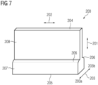
- the Figure 7 shows a schematic representation of a moving contact 200 according to the invention for a safety switch 100 according to the invention.
- the moving contact 200 has a thickening 207 with a coupling side 205 to the spring accumulator 340, whereby the coupling to the spring accumulator is via a Figure 1 shown electrically insulating connecting piece 190.
- the thickening 207 On the side opposite the coupling side 205, the thickening 207 here has an optional rounded edge 206 or shoulder 206 of the thickening 207 of the moving contact 200.
- the thinner region 208 of the moving contact 200 has an upper side 204 of the moving contact 200.
- the moving contact When properly mounted, the moving contact can therefore be moved along the direction of movement 201.
- the thickening 207 of the moving contact 200 serves to electrically contact the fixed contacts 215 in the closed state, while the fixed contacts in the open state are electrically separated from the moving contact 200 in the vicinity of the thinner area 208 of the moving contact 200.
- the moving contact 200 By moving the moving contact 200 in the direction of movement 201 of the moving contact 200, the moving contact can be changed from the closed state to the open state and vice versa.
- the Figure 8 shows a schematic representation of an arrangement according to the invention of fixed contacts 215, 215', 235' around the moving contact 200 from a first side 203a of the moving contact 200, with a current band 250, for a safety switch 100 according to the invention.
- the moving contact 200 again has a thickening 207 with a shoulder 206 and a thinner region 208.
- first fixed contact 215 and a second first fixed contact 215' are arranged in a first fixed contact arrangement 214 and a second third fixed contact 235' of the third fixed contact arrangement 234.
- the open state of the safety switch 100 is shown.
- the first fixed contact arrangement 214 and the second third fixed contact 235' are further apart from each other than the first first fixed contact 215 and the second first fixed contact 215' are apart from each other. This greater spacing between the first fixed contact arrangement 214 and the third fixed contact arrangement 234 results in improved electrical insulation of different phases while at the same time making the safety switch 100 more compact.
- FIG. 9 time schematic representation of an inventive arrangement of fixed contacts 225, 225', 235 around the moving contact 200 from a second side 203b of the moving contact 200, with a current band 250, for a safety switch 100 according to the invention.
- the moving contact 200 again has a thickening 207 with a shoulder 206 and a thinner region 208.
- a first second fixed contact 225 and a second second fixed contact 225' are arranged in a second fixed contact arrangement 224 and a first third fixed contact 235 of the third fixed contact arrangement 234.
- the open state of the safety switch 100 is shown.
- the second fixed contact arrangement 224 and the first third fixed contact 235 are further apart from each other than the first second fixed contact 225 and the second second fixed contact 225' are apart from each other. This greater spacing between the second fixed contact arrangement 224 and the third fixed contact arrangement 234 results in an improved electrical isolation of different phases while maintaining the compactness of the safety switch 100.
Landscapes
- Physics & Mathematics (AREA)
- Electromagnetism (AREA)
- Push-Button Switches (AREA)
Description
- Die Erfindung bezieht sich auf einen schnellen Sicherheitsschalter und ein System mit einem solchen Sicherheitsschalter.
- Sicherheitsschalter, auch Schnellerder oder Kurzschlussschalter, sind insbesondere aus der Mittelspannung, also zwischen 1000V und etwa 52,5kV zum Löschen von Lichtbögen im Fehlerfall bekannt. Auch unterhalb von 1000V Nennspannung besteht aber ein Bedarf an solchen Sicherheitsschaltern.
- Aus dem Stand der Technik sind Geräte für Mittelspannungsanwendungen bekannt, die Schaltzeiten von unter 5ms mittels eines einpoligen Schalters und einer Sprengladung als Antrieb erreichen. Eine Wiederverwendung des Schalters ist nach Auslösung nicht möglich.
- Weiter bekannt ist auch ein System, bei dem ein elektromagnetischer Antrieb drei Pole in einem Vorgang schaltet, wobei der Schalteraufbau hier komplex ist.
- Weiter bekannt ist auch eine Vorrichtung mit einer elektromagnetischen Entklinkung, Auslösung und einem Federantrieb.
- Die Verwendung eines Magnetauslösers mit einer Verklinkung ist gemäß der
DE102018216210A1 bekannt. - Aus der
EP 2 677 530 A3 ist ein linear angetriebener Erdungsschalter mit Seiten- und Deckenabdeckung bekannt, der mittels eines Federantriebs oder eines Getriebes angetrieben in eine geschlossene - geerdete - Position überführt wird und mit dem Getriebe und einem Werkzeug in die offene Stellung überführt wird. In der offenen Stellung sind drei Festkontakte von den Bewegkontakten getrennt und in der geschlossenen Stellung kontaktieren sich die Bewegkontakte und Festkontakte. - Aufgabe der Erfindung ist es nun einen verbesserten Sicherheitsschalter bereitzustellen, der Nachteile aus dem Stand der Technik behebt.
- Ein Ausführungsbeispiel bezieht sich auf einen schnellen Sicherheitsschalter, wobei der schnelle Sicherheitsschalter ein Schaltergehäuse aufweist, wobei das Schaltergehäuse aufweist:
- sechs Gehäuseaußenseiten, mit einer Gehäusefrontseite, einer offenen Gehäuserückseite, einer Gehäuseoberseite, einer Gehäuseunterseite, einer ersten Gehäuseseite und einer zweiten Gehäuseseite,
- eine Bedienwerkzeugschnittstelle, die durch eine der Gehäuseaußenseiten bedienbar ist, und
- ein oder mehr Anschlusselemente zur Steuerung des schnellen Sicherheitsschalters,
- der schnelle Sicherheitsschalter mit einem elektromagnetischen Auslöser entklinkbar ist und der schnelle Sicherheitsschalter einen Bewegkontakt, inbesondere einen einzigen Bewegkontakt, aufweist, der mittels einem Federspeicher bewegbar ist, wobei der Federspeicher in einer vorgespannten Position verklinkt ist und die Verklinkung mit dem elektromagnetischen Auslöser lösbar ist,
- der Bewegkontakt derart ausgestaltet ist, dass der Bewegkontakt in einer ersten Position:
- elektrisch leitend mit einem vierten Polanschluss verbunden ist, und
- elektrisch getrennt von einem ersten Polanschluss und einem zweiten Polanschluss und einem dritten Polanschluss angeordnet ist,
- und dass der Bewegkontakt in einer zweiten Position:
- elektrisch leitend mit einem vierten Polanschluss verbunden ist, und
- den ersten Polanschluss und den zweiten Polanschluss und den dritten Polanschluss elektrisch leitend und kontaktierend angeordnet ist,
- wobei der schnelle Sicherheitsschalter durch das Entklinken mit dem elektromagnetischen Auslöser von der ersten Position in die zweite Position überführbar ist und wobei der schnelle Sicherheitsschalter über die Bedienwerkzeugschnittstelle von der zweiten Position in die erste Position überführbar ist. Insbesondere ist dieser Sicherheitsschalter für Betriebsspannungen unterhalb von 1000V ausgelegt.
- Bevorzugt wird, dass der schnelle Sicherheitsschalter eine erste Festkontaktanordnung, eine zweite Festkontaktanordnung und eine dritte Festkontaktanordnung aufweist, wobei die erste Festkontaktanordnung elektrisch leitend mit dem ersten Polanschluss verbunden ist, die zweite Festkontaktanordnung elektrisch leitend mit dem zweiten Polanschluss verbunden ist und die dritte Festkontaktanordnung elektrisch leitend mit dem dritten Polanschluss verbunden ist,
und der Bewegkontakt ausgestaltet ist, bei einem Übergang von der ersten Position in die zweite Position die ersten Festkontaktanordnung, die zweite Festkontaktanordnung und die dritte Festkontaktanordnung nahezu gleichzeitig, also bevorzugt innerhalb von 1ms, zu kontaktieren, so dass die erste Festkontaktanordnung, die zweite Festkontaktanordnung und die dritte Festkontaktanordnung nahezu gleichzeitig miteinander und dem vierten Polanschluss elektrisch leitend verbunden sind. - Auch wird bevorzugt, dass der Bewegkontakt eine erste Ausdehnung, eine zweite Ausdehnung und eine dritte Ausdehnung aufweist, wobei die erste Ausdehnung parallel zu den Bewegungsrichtungen des Bewegkontaktes liegt und der Bewegkontakt entlang der ersten Ausdehnung eine Verdickung in der dritten Ausdehnung aufweist, wobei die erste Festkontaktanordnung, die zweite Festkontaktanordnung und die dritte Festkontaktanordnung in der zweiten Position den Bewegkontakt an der Verdickung elektrisch kontaktieren.
- Bevorzugt wird auch, dass die erste Festkontaktanordnung, die zweite Festkontaktanordnung und die dritte Festkontaktanordnung in der ersten Position den Bewegkontaktan einem gegenüber der Verdickung dünneren Bereich des Bewegkontaktes derart angeordnet sind, dass die erste Festkontaktanordnung, die zweite Festkontaktanordnung und die dritte Festkontaktanordnung in der ersten Position vom Bewegkontakt beabstandet sind und den Bewegkontakt nicht elektrisch kontaktieren.
- Weiter wird bevorzugt, dass die erste Festkontaktanordnung einen ersten ersten Festkontakt auf einer ersten Seite des Bewegkontaktes und einen zweiten ersten Festkontakt auf der ersten Seite des Bewegkontaktes aufweist,
- die zweite Festkontaktanordnung einen ersten zweiten Festkontakt auf einer zweiten Seite des Bewegkontaktes und einen zweiten zweiten Festkontakt auf der zweiten Seite des Bewegkontaktes aufweist, und
- die dritte Festkontaktanordnung einen ersten dritten Festkontakt auf der ersten Seite des Bewegkontaktes und einen zweiten dritten Festkontakt auf einer zweiten Seite des Bewegkontaktes aufweist. Dies bewirkt eine gleichmäßige Belastung und Kraftbeaufschlagung für den Bewegkontakt beim Kontaktieren der Festkontakte.
- Bevorzugt wird auch, dass jeweils die erste Festkontaktanordnung, die zweite Festkontaktanordnung und die dritte Festkontaktanordnung derart mit einer Kraft beaufschlagt und angeordnet sind, dass die erste Festkontaktanordnung, die zweite Festkontaktanordnung und die dritte Festkontaktanordnung in der ersten Position jeweils den Bewegkontakt nicht elektrisch kontaktieren und in der zweiten Position den Bewegkontakt elektrisch kontaktieren und mit jeweils einer Haltekraft an den Bewegkontakt gedrückt werden.
- Auch wird bevorzugt, dass jede der Festkontaktanordnungen mit einer Stromband-Kontakt-Kombination gebildet werden, wobei die Stromband-Kontakt-Kombination jeweils mit
- einem Bewegelement, das mit einem oder mehr von einem Gewebeband oder Litzen oder Lamellen gebildet ist, wobei das Bewegelement
- ∘ ein erstes Bewegelementende und ein zweites Bewegelementende aufweist und
- ∘ das erste Bewegelementende einen ersten Bewegelementanschluss aufweist, der mittels Schweißen, Pressen und/oder Löten gebildet ist und das zweite Bewegelementende einen zweiten Bewegelementanschluss aufweist, der mittels Schweißen, Pressen und/oder Löten gebildet ist,
- einem Festkontakt, der am erste Bewegelementanschluss oder zweiten Bewegelementanschluss angeordnet ist, gebildet ist,
- Beweglich anordbar ist hier so zu verstehen, dass in einer ordnungsgemäß montierten Weise der Festkontakt eine Beweglichkeit aufweist, die insbesondere eine beschränkte Ausweichbewegung erlaubt, bei der der Festkontakt bei einem Auftreffen eines Bewegkontaktes auf den Festkontakt eine beschränkte Ausweichbewegung vom Bewegkontakt weg, insbesondere eine Ausweichbewegung senkrecht zu einer Bewegungsrichtung des Bewegkontaktes, erlaubt. Mit anderen Worten beweglich anordbar bedeutet hier, dass der Festkontakt durch den Bewegkontakt bewegbar ist, insbesondere der Festkontakt eine Ausweichbewegung in Bezug auf den Bewegkontakt, insbesondere senkrecht zur Bewegungsrichtung des Bewegkontaktes ausführen kann. Der Festkontakt ist also kein aktiv bewegtes Element, sondern ein durch den Bewegkontakt bewegbares, insbesondere zu einer beschränkten Ausweichbewegung ausgestaltetes Element.
- Der Festkontakt kann dabei vollständig von dem oder den Festkontaktfingern gebildet werden oder noch weitere Elemente, wie einen Festkontaktfingerträger, einen Festkontaktträger oder eine Ausweichbewegungsbeschränkung aufweisen.
- Eine solche Segmentierung, also Aufspaltung, des Festkontaktes in einzelne Festkontaktfinger führt zu einer höheren Zuverlässigkeit bei der Kontaktierung zwischen Bewegkontakt und Festkontakt.
- Insbesondere wird bevorzugt, dass der Festkontakt zwei oder mehr Festkontaktfinger aufweist, wobei
- die Festkontaktfinger mit dem ersten Bewegelementende oder dem zweiten Bewegelementende verbunden sind, und
- das mit den Festkontaktfingern verbundene erste Bewegelementende oder zweite Bewegelementende zusammen mit einem ersten Bewegelementabschnitt des Bewegelementes derart geschlitzt, also segmentiert, ist, dass das mit den Festkontaktfingern verbundene erste Bewegelementende oder zweite Bewegelementende Bewegelementendsegmente aufweist und jeweils nur ein Festkontaktfinger mit jeweils einem Bewegelementendsegment verbunden ist.
- Besonders bevorzugt wird, dass jeder der zwei oder mehr Festkontaktfinger mit jeweils einem Bewegelementsegment durch Löten, Schweißen oder Pressen verbunden ist.
- Auch wird bevorzugt, dass jeder der zwei oder mehr Festkontaktfinger eine erste Aufnahme für eine Ausweichbewegungsbeschränkung aufweist. Das ermöglicht eine definierte, also vorbestimmte zulässige Ausweichbewegung, insbesondere ohne dabei eine sichere, also zuverlässige, Kontaktierung zu gefährden.
- Bevorzugt wird auch, dass jeder der zwei oder mehr Festkontaktfinger eine zweite Aufnahme für einen Festkontaktfingerträger aufweist. Eine solche zweite Aufnahme für einen Festkontaktfingerträger ermöglicht eine modulare Vorfertigung, also die Möglichkeit, die Festkontakte in einem Festkontaktfingerträger als eine Baugruppe zu montieren und dann diese Baugruppe einfach in ein vorgegebenes Kontaktsystem zu integrieren. Eine solche Vormontage reduziert Montagekosten, Montagezeit und die Montagezuverlässigkeit, also die Reduzierung von Fehlerquellen, insbesondere wenn solche vormontierte Baugruppen separat getestet werden.
- Weiter wird bevorzugt, dass an dem ersten Bewegelementende oder dem zweite Bewegelementende, das nicht mit dem Festkontakt verbunden ist, eine Befestigungsmittelaufnahme vorgesehen ist. Eine solche Befestigungsmittelaufnahme ermöglicht einfaches Verbinden der Stromband-Kontakt-Kombination mit einem Kontaktsystem, insbesondere ohne stoffschlüssige Verbindungen zu fordern.
- Bevorzugt wird auch, dass am Festkontakt eine oder mehr Krafteinleitungspunkte vorgesehen sind. Solche Krafteinleitungspunkte ermöglichen ein Aufbringen einer Kraft, insbesondere einer Federkraft, auf den Festkontakt, die bevorzugt entgegen der möglichen Richtung der Ausweichbewegung gerichtet ist. So kann ein zusätzlicher Anpressdruck zwischen dem Festkontakt und einem Bewegkontakt in dem Zustand erzeugt werden, in dem der Bewegkontakt den Festkontakt elektrisch kontaktiert. Insbesondere ist die Richtung der Ausweichbewegung senkrecht zur Richtung der Bewegung des Bewegkontaktes.
- Auch wird bevorzugt, dass jede Stromband-Kontakt-Kombination derart U-förmig, mit einem ersten Schenkel des U, also der U-Form, und einem zweiten Schenkel des U, also der U-Form, angeordnet ist, dass in der zweiten Position des schnellen Sicherheitsschalters ein Stromfluss durch die Stromband-Kontakt-Kombinationen eine abstoßende Kraft zwischen dem jeweils ersten Schenkel des U und dem zweiten Schenkel des U bewirkt, und so jeweils den Festkontakt gegen den Bewegkontakt drückt und so den Kontaktandruck erhöht.
- Dabei bilden insbesondere das Bewegelement und der Festkontakt die U-Form aus, das heißt, der erste Bewegelementanschluss oder der zweite Bewegelementanschluss bildet bevorzugt einen ersten Schenkel der U-Form und der Festkontakt bildet bevorzugt einen zweiten Schenkel der U-Form.
- Bevorzugt wird auch, dass der erste Polanschluss, der zweite Polanschluss, der dritte Polanschluss und der vierte Polanschluss auf einer dem elektromagnetischen Auslöser gegenüberliegenden Seite angeordnet sind und der Bewegkontakt über ein oder mehr Strombänder mit dem vierten Polanschluss verbunden ist. Die Stromzuführung zu dem Bewegkontakt erfolgt also von der gleichen Seite wie die Anschlüsse für die Festkontakte. Hinsichtlich der erfindungsgemäßen Einrichtung gelten alle zu dem erfindungsgemäßen Verfahren voranstehend und nachfolgend gemachten Ausführungen und umgekehrt in entsprechender Weise, insbesondere ist die erfindungsgemäße Einrichtung zur Durchführung des erfindungsgemäßen Verfahrens in jeder beliebigen Ausführungsform oder einer Kombination beliebiger Ausführungsformen eingerichtet. Auch hinsichtlich der Vorteile der erfindungsgemäßen Einrichtung wird auf die zu dem erfindungsgemäßen Verfahren beschriebenen Vorteile verwiesen.
- Die Erfindung wird nachfolgend anhand eines Ausführungsbeispiels näher erläutert.
- Figur 1:
- Schematische Schnittdarstellung eines erfindungsgemäßen Sicherheitsschalters im offenen und verklinkten Zustand;
- Figur 2:
- Schematische Schnittdarstellung eines erfindungsgemäßen Sicherheitsschalters im geschlossenen und entklinkten Zustand;
- Figur 3:
- Schematische Schnittdarstellung eines erfindungsgemäßen Sicherheitsschalters;
- Figur 4:
- Schematische perspektivische Darstellung eines erfindungsgemäßen Sicherheitsschalters;
- Figur 5:
- Schematische Darstellung einer erfindungsgemäßen Stromband-Kontakt-Kombination für einen erfindungsgemäßen Sicherheitsschalter;
- Figur 6:
- Schematische Darstellung einer erfindungsgemäßen Stromband-Kontakt-Kombination mit Festkontaktfingern für einen erfindungsgemäßen Sicherheitsschalter;
- Figur 7:
- Schematische Darstellung eines erfindungsgemäßen Bewegkontaktes für einen erfindungsgemäßen Sicherheitsschalter;
- Figur 8:
- Schematische Darstellung einer erfindungsgemäßen Anordnung von Festkontakten um den Bewegkontakt von einer ersten Seite des Bewegkontaktes für einen erfindungsgemäßen Sicherheitsschalter;
- Figur 9:
- Schematische Darstellung einer erfindungsgemäßen Anordnung von Festkontakten um den Bewegkontakt von einer zweiten Seite des Bewegkontaktes für einen erfindungsgemäßen Sicherheitsschalter.
- Die
Figur 1 zeigt eine schematische Schnittdarstellung eines erfindungsgemäßen Sicherheitsschalters 100 im offenen und verklinkten Zustand. - Der Sicherheitsschalter 100 weist ein Gehäuse auf, wobei von dem Gehäuse in der
Figur 1 eine offene Gehäuserückseite 114, eine erste Gehäuseseite 117, eine zweite Gehäuseseite 118 und eine Gehäusefrontseite sichtbar sind. Die Gehäuseoberseite 115 und Gehäuseunterseite 116 sind in derFigur 1 nicht dargestellt. - In dem in der
Figur 1 dargestellten offenen Zustand kontaktieren die Festkontakte 215, hier sichtbar der erste erste Festkontakt 215 und der erste zweite Festkontakt 225, nicht den Bewegkontakt 200, das heißt die Festkontakte 215 sind elektrisch getrennt, isoliert, von dem Bewegkontakt 200. Die Verklinkung 310 ist verriegelt, also der Sicherheitsschalter 100 verklinkt. Die Verklinkung 310 kann durch den elektromagnetischen Auslöser 300 ausgelöst, also entklinkt, werden. Das Entklinken der Verklinkung 310 bewirkt, dass ein Energiespeicher, hier ein mechanischer Energiespeicher in Form eines Federspeichers 340, insbesondere in Form eines Tellerfederpaketes, die gespeicherte Energie frei gibt, hier insbesondere in Form einer Bewegung des Bewegkontaktes 200. Der Federspeicher 340 ist mittels der Bedienwerkzeugschnittstelle 120 spannbar, also wieder mit Energie beaufschlagbar. Weiter wird mittels der Bedienwerkzeugschnittstelle 120 die Verklinkung nach dem Spannen des Federspeichers 340 wieder von der entklinkten Position in die verklinkte Position überführt, so dass mittels des elektromagnetischen Auslösers 300 eine erneute Schalthandlung auslösbar ist. Der elektromagnetische Auslöser 300, die Verklinkung 310 und der Federspeicher 340 bilden hier den Antrieb des Sicherheitsschalters 100. - Der Federspeicher 100 ist mit dem Bewegkontakt 200 mechanisch verbunden, wobei der Federspeicher 340 bevorzugt über ein elektrisch isolierendes Verbindungsstück 190 mit dem Bewegkontakt 200 mechanisch verbunden ist.
- Der Bewegkontakt ist beweglich, aber elektrisch leitend, mit einem vierten Polanschluss 240 verbunden, wobei die bewegliche und elektrisch leitende Verbindung bevorzugt mittels eines oder mehrerer Strombänder 250, insbesondere zwei Strombänder 250, erfolgt.
- Der vierte Polanschluss 240 ist auf der offenen Gehäuserückseite 114 angeordnet. Auch an der offenen Gehäuserückseite 114 angeordnet sind der erste Polanschluss 210, der zweite Polanschluss 220 und der dritte Polanschluss 230. Der erste Polanschluss 210, der zweite Polanschluss 220, der dritte Polanschluss 230 und der vierte Polanschluss 240 sind dabei elektrisch voneinander isoliert angeordnet, was durch nicht gezeigt dielektrische Zwischenelemente, durch eine hier nicht gezeigte Beabstandung, siehe aber
Figur 4 , oder eine isolierende Beschichtung realisierbar ist. - Die
Figur 2 zeigt eine schematische Schnittdarstellung des erfindungsgemäßen Sicherheitsschalters 100 derFigur 1 im geschlossenen und entklinkten Zustand. - Der Sicherheitsschalter 100 weist ein Gehäuse auf, wobei von dem Gehäuse in der
Figur 2 eine offene Gehäuserückseite 114, eine erste Gehäuseseite 117, eine zweite Gehäuseseite 118 und eine Gehäusefrontseite sichtbar sind. Die Gehäuseoberseite 115 und Gehäuseunterseite 116 sind in derFigur 2 nicht dargestellt. - In dem in der
Figur 2 dargestellten geschlossene Zustand kontaktieren die Festkontakte 215, hier sichtbar der erste erste Festkontakt 215 und der erste zweite Festkontakt 225, den Bewegkontakt 200 elektrisch. Die Verklinkung 310 ist entriegelt, also der Sicherheitsschalter 100 entklinkt. Die Verklinkung 310 ist durch den elektromagnetischen Auslöser 300 ausgelöst, also entklinkt. - Die Festkontakte 215, hier erkennbar der erste erste Festkontakt 215 und der erste zweite Festkontakt 225, sind jeweils mit einer Ausweichbewegungsbeschränkung 150 und einem Festkontaktfingerträger 160 verbunden. Die jeweils zum Verbinden genutzte erste Aufnahme 216 für die Ausweichbewegungsbeschränkung 150 und zweite Aufnahme 217 für den Festkontaktfingerträger sind in den
Figuren 5 und 6 gezeigt, nicht aber derFigur 2 . - Der Federspeicher 340 ist mittels der Bedienwerkzeugschnittstelle 120 spannbar, also wieder mit Energie beaufschlagbar. Weiter wird mittels der Bedienwerkzeugschnittstelle 120 die Verklinkung nach dem Spannen des Federspeichers 340 wieder von der entklinkten Position in die verklinkte Position der
Figur 1 überführt, so dass mittels des elektromagnetischen Auslösers 300 eine erneute Schalthandlung auslösbar ist. Der elektromagnetische Auslöser 300, die Verklinkung 310 und der Federspeicher 340 bilden auch hier den Antrieb des Sicherheitsschalters 100. - Der Bewegkontakt ist beweglich, aber elektrisch leitend, mit einem vierten Polanschluss 240 verbunden, wobei die bewegliche und elektrisch leitende Verbindung bevorzugt mittels eines oder mehrerer Strombänder 250, insbesondere zwei oder vier Strombänder 250, erfolgt.
- Der vierte Polanschluss 240 ist auf der offenen Gehäuserückseite 114 angeordnet. Auch an der offenen Gehäuserückseite 114 angeordnet sind der erste Polanschluss 210, der zweite Polanschluss 220 und der dritte Polanschluss 230. Der erste Polanschluss 210, der zweite Polanschluss 220, der dritte Polanschluss 230 und der vierte Polanschluss 240 sind dabei elektrisch voneinander isoliert angeordnet, was durch nicht gezeigt dielektrische Zwischenelemente, durch eine hier nicht gezeigte Beabstandung, siehe aber
Figur 4 , oder eine isolierende Beschichtung realisierbar ist. - Die
Figur 3 zeigt eine schematische Schnittdarstellung eines erfindungsgemäßen Sicherheitsschalters 100 mit der offenen Gehäuserückseite 114, der Gehäusefrontseite 113 mit Bedienwerkzeugschnittstelle 120, der Gehäuseoberseite 115 und der Gehäuseunterseite 116 mit Anschlusselementen 130. Die Anschlusselemente 130 dienen der elektrischen und/oder optischen Kontaktierung zum Ansteuern Monitoren des Sicherheitsschalters 100, bieten also eine Kommunikationsschnittstelle. In der Darstellung derFigur 3 sind der erste zweite Festkontakt 225, der zweite zweite Festkontakt 225` und der erste dritte Festkontakt 235 auf einer Seite des Bewegkontaktes 200 dargestellt. - Einige der Anschlusselemente 130 sind mit dem elektromagnetischen Auslöser 300 verbunden, so dass der elektromagnetische Auslöser 300 über diese Verbindung ausgelöst und optional auch überwacht werden kann. Weiter optional sind einige Anschlusselemente 130 mit einer Positionsbestimmung 315 derart verbunden, dass die Position der Verklinkung überwacht werden kann.
- Die
Figur 4 zeigt eine schematische perspektivische Darstellung eines erfindungsgemäßen Sicherheitsschalters 100, mit der offenen Gehäuserückseite 114, der Gehäuseunterseite 116 mit Anschlusselementen 130, der ersten Gehäuseseite 117 und der zweiten Gehäuseseite 118. - An der offenen Gehäuserückseite 114 sind der erste Polanschluss 210, der zweite Polanschluss 220, der dritte Polanschluss 230 und der vierte Polanschluss 240 voneinander elektrisch isoliert angeordnet, was hier durch eine Beabstandung des ersten Polanschlusses 210, des zweiten Polanschlusses 220, des dritten Polanschlusses 230 und des vierten Polanschlusses 240 erreicht ist. Der vierte Polanschluss 240 ist hier durch ein optionales, elektrisch isolierendes Halteelement 245 zusätzlich befestigt.
- Der vierte Polanschluss 240 ist mit vier sichtbaren Strombändern 250 mit dem hier nicht gezeigten Bewegkontakt 200 elektrisch leitend verbunden, wobei zwei der Strombänder 250 sichtbar und zwei Strombänder von dem vierten Polanschluss 240 verdeckt sind.
- Die
Figur 5 zeigt eine schematische Darstellung einer erfindungsgemäßen Stromband-Kontakt-Kombination 1 mit einem Festkontakt 215 und einem Bewegelement 255. Das Bewegelement 255 weist ein erstes Bewegelementende 256 und ein zweites Bewegelementende 257 auf. Das erste Bewegelementende 256 bildet mittels Schweißen, Pressen und/oder Löten einen ersten Bewegelementanschluss und das zweites Bewegelementende 257 bildet mittels Schweißen, Pressen und/oder Löten einen zweiten Bewegelementanschluss. An dem zweiten Bewegelementanschluss am zweiten Bewegelementende 257 ist hier beispielhaft der Festkontakt 215 angeordnet. Der erste Bewegelementanschluss am ersten Bewegelementende 256 weist hier beispielhaft und bevorzugt zwei Befestigungsmittelaufnahmen 254 auf. Der Festkontakt 215 weist hier beispielhaft eine erste Aufnahme 216 für eine nicht gezeigte Ausweichbewegungsbeschränkung 150 auf. - Weiter ist eine optionale zweite Aufnahme 217 am Festkontakt gezeigt, die zur Aufnahme eines hier nicht gezeigten Festkontaktfingerträger dienen.
- Der Festkontakt 215 ist derart mit dem zweiten Bewegelementanschluss verbunden, dass der Festkontakt 215 durch das Bewegelement 255 bewegbar ist. Insbesondere ist der Festkontakt so in der Lage eine Ausweichbewegung in Bezug auf einen nicht gezeigten Bewegkontakt auszuführen, wobei der Bewegkontakt eine Bewegungsrichtung 201 aufweist und der Festkontakt 215 eine Bewegung in eine weitere Bewegungsrichtung 203 senkrecht zur Bewegungsrichtung 201 des Bewegkontaktes ausführen kann.
- Die Verbindung des Festkontakt 215 mit dem zweiten Bewegelementanschluss erfolgt bevorzugt mittel Schweißen, Pressen, Schrauben, Nieten und/oder Löten, besonders bevorzugt mittels Schweißen.
- Weiter sind optional Krafteinleitungspunkte 218 vorgesehen, die ein Aufbringen einer Kraft, insbesondere einer Federkraft, auf die Festkontakte 215, die bevorzugt entgegen der möglichen Richtung der Ausweichbewegung gerichtet ist.
- Die
Figur 6 zeigt eine schematische Darstellung einer erfindungsgemäßen Stromband-Kontakt-Kombination 1 mit Festkontaktfingern 215a, 215b, 215c, 215d und einem Bewegelement 255 mit einem ersten Bewegelementende 256 und einem zweiten Bewegelementende 257 auf. - Das Bewegelement 255 ist in einem ersten Bewegelementabschnitt 255a hin zum zweiten Bewegelementende 257 derart geschlitzt oder segmentiert, dass Bewegelementendsegmente 255b, 255c, 255d, 255e gebildet sind, die jeweils mit einem Festkontaktfinger 215a, 215b, 215c, 215d verbunden sind. Dadurch ist in diesem Ausführungsbeispiel jeder der Festkontaktfinger 215a, 215b, 215c, 215d einzeln beweglich.
- Das erste Bewegelementende 256 bildet mittels Schweißen, Pressen und/oder Löten einen ersten Bewegelementanschluss und das zweites Bewegelementende 257 bildet mittels Schweißen, Pressen und/oder Löten einen zweiten Bewegelementanschluss. An dem zweiten Bewegelementanschluss am zweiten Bewegelementende 257 sind hier beispielhaft die Festkontaktfinger 215a, 215b, 215c, 215d angeordnet. Der erste Bewegelementanschluss am ersten Bewegelementende 256 weist hier beispielhaft und bevorzugt zwei Befestigungsmittelaufnahmen 254 auf. Die Festkontaktfinger 215a, 215b, 215c, 215d weisen hier beispielhaft jeweils erste Aufnahmen 216 für eine nicht gezeigte Ausweichbewegungsbeschränkung auf.
- Weiter ist eine optionale zweite Aufnahme 217 an den einzelnen Festkontaktfingern 215a, 215b, 215c, 215d gezeigt, die zur Aufnahme eines hier nicht gezeigten Festkontaktfingerträgers dienen.
- Die Festkontaktfinger 215a, 215b, 215c, 215d sind derart mit dem zweiten Bewegelementanschluss verbunden, dass die Festkontaktfinger 215a, 215b, 215c, 215d durch das Bewegelement 255 bewegbar sind. Insbesondere sind die Festkontaktfinger so in der Lage eine Ausweichbewegung in Bezug auf einen nicht gezeigten Bewegkontakt auszuführen, wobei der Bewegkontakt eine Bewegungsrichtung 201 aufweist und der Festkontakt 215 eine Bewegung in eine weitere Bewegungsrichtung 203 senkrecht zur Bewegungsrichtung 201 des Bewegkontaktes ausführen kann.
- Die Verbindung der Festkontaktfinger 215a, 215b, 215c, 215d mit dem zweiten Bewegelementanschluss, bzw. mit den Bewegelementsegmenten 255b, 255c, 255d, 255e erfolgt bevorzugt mittel schweißen, pressen, schrauben, nieten und/oder löten, besonders bevorzugt mittels schweißen.
- Weiter sind optional Krafteinleitungspunkte 218 vorgesehen, die ein Aufbringen einer Kraft, insbesondere einer Federkraft, auf die Festkontaktfinger 215a, 215b, 215c, 215d, die bevorzugt entgegen der möglichen Richtung der Ausweichbewegung gerichtet ist.
- Die
Figur 7 zeigt eine schematische Darstellung eines erfindungsgemäßen Bewegkontaktes 200 für einen erfindungsgemäßen Sicherheitsschalter 100. - Der Bewegkontakt 200 verfügt hier über eine Verdickung 207 mit einer Ankopplungsseite 205 an den Federspeicher 340, wobei die Ankopplung an den Federspeicher über ein in
Figur 1 gezeigtes elektrisch isolierendes Verbindungsstück 190 erfolgen kann. Auf der der Ankopplungsseite 205 gegenüberliegenden Seite weist die Verdickung 207 hier eine optionale abgerundete Kante 206 oder Schulter 206 der Verdickung 207 des Bewegkontaktes 200 auf. - Der dünneren Bereich 208 des Bewegkontaktes 200 weist eine Oberseite 204 des Bewegkontaktes 200 auf.
- Der Bewegkontakt weist:
- eine erste Ausdehnung 201 auf, die auch eine Bewegrichtung 201 des Bewegkontaktes 200 ist;
- eine zweite Ausdehnung 202 des Bewegkontaktes 200 auf; und
- eine dritte Ausdehnung 203 des Bewegkontaktes 200 auf, die auch eine weitere Bewegungsrichtung 203 senkrecht zur Bewegungsrichtung 201 des Bewegkontaktes 200 ist.
- Der Bewegkontakt ist also im ordnungsgemäß montierten Zustand entlang der Bewegrichtung 201 bewegbar.
- Die Verdickung 207 des Bewegkontaktes 200 dient der elektrischen Kontaktierung der Festkontakte 215 im geschlossenen Zustand, während sich die Festkontakte im geöffneten Zustand elektrisch getrennt vom Bewegkontakt 200 im Umfeld des dünneren Bereichs 208 des Bewegkontaktes 200 befinden.
- Durch die Bewegung des Bewegkontaktes 200 in die Bewegrichtung 201 des Bewegkontaktes 200 kann der Bewegkontakt von dem geschlossenen Zustand in den offenen Zustand und umgekehrt überführt werden.
- Die
Figur 8 zeigt eine schematische Darstellung einer erfindungsgemäßen Anordnung von Festkontakten 215, 215', 235' um den Bewegkontakt 200 von einer ersten Seite 203a des Bewegkontaktes 200, mit einem Stromband 250, für einen erfindungsgemäßen Sicherheitsschalter 100. - Der Bewegkontakt 200 weist wieder eine Verdickung 207 mit einer Schulter 206 und einen dünneren Bereich 208 auf.
- Auf der ersten Seite 203a des Bewegkontaktes 200 ist ein erster erster Festkontakt 215 und ein zweiter erster Festkontakt 215' in einer erste Festkontaktanordnung 214 und ein zweiter dritter Festkontakt 235' der dritten Festkontaktanordnung 234 angeordnet. Dargestellt ist der offene Zustand des Sicherheitsschalters 100. In der gezeigten bevorzugten Ausführung sind die erste Festkontaktanordnung 214 und der zweite dritte Festkontakt 235' voneinander weiter beabstandet als der erste erste Festkontakt 215 und der zweite erste Festkontakt 215' voneinander beabstandet sind. Diese größere Beabstandung zwischen erster Festkontaktanordnung 214 und dritter Festkontaktanordnung 234 bewirken eine verbesserte elektrische Isolation von unterschiedlichen Phasen bei gleichzeitiger Kompaktheit des Sicherheitsschalters 100.
- Die
Figur 9 zeit schematische Darstellung einer erfindungsgemäßen Anordnung von Festkontakten 225, 225', 235 um den Bewegkontakt 200 von einer zweiten Seite 203b des Bewegkontaktes 200, mit einem Stromband 250, für einen erfindungsgemäßen Sicherheitsschalter 100. - Der Bewegkontakt 200 weist wieder eine Verdickung 207 mit einer Schulter 206 und einen dünneren Bereich 208 auf.
- Auf der zweiten Seite 203b des Bewegkontaktes 200 ist ein erster zweiter Festkontakt 225 und ein zweiter zweiter Festkontakt 225' in einer zweiten Festkontaktanordnung 224 und ein erster dritter Festkontakt 235 der dritten Festkontaktanordnung 234 angeordnet. Dargestellt ist der offene Zustand des Sicherheitsschalters 100. In der gezeigten bevorzugten Ausführung sind die zweite Festkontaktanordnung 224 und der erste dritte Festkontakt 235 voneinander weiter beabstandet als der erste zweite Festkontakt 225 und der zweite zweite Festkontakt 225' voneinander beabstandet sind. Diese größere Beabstandung zwischen zweiter Festkontaktanordnung 224 und dritter Festkontaktanordnung 234 bewirken eine verbesserte elektrische Isolation von unterschiedlichen Phasen bei gleichzeitiger Kompaktheit des Sicherheitsschalters 100.
-
- 1
- Stromband-Kontakt-Kombination
- 100
- schneller Sicherheitsschalter;
- 110
- Schaltergehäuse des schnellen Sicherheitsschalters (100) ;
- 112
- Gehäuseaußenseiten, insgesamt sechs;
- 113
- Gehäusefrontseite;
- 114
- offene Gehäuserückseite;
- 115
- Gehäuseoberseite;
- 116
- Gehäuseunterseite;
- 117
- erste Gehäuseseite;
- 118
- zweite Gehäuseseite;
- 120
- Bedienwerkzeugschnittstelle;
- 130
- Anschlusselemente;
- 150
- Ausweichbewegungsbeschränkung;
- 160
- Festkontaktfingerträger;
- 190
- elektrisch isolierendes Verbindungsstück;
- 200
- Bewegkontakt;
- 201
- erste Ausdehnung des Bewegkontaktes und Bewegrichtung des Bewegkontaktes 200;
- 202
- zweite Ausdehnung des Bewegkontaktes 200;
- 203
- dritte Ausdehnung des Bewegkontaktes 200 und weitere Bewegungsrichtung senkrecht zur Bewegungsrichtung des Bewegkontaktes 200;
- 203a
- erste Seite des Bewegkontaktes 200;
- 203b
- zweite Seite des Bewegkontaktes 200;
- 204
- Oberseite des Bewegkontaktes 200;
- 205
- Ankopplungsseite an den Federspeicher 340;
- 206
- abgerundete Kante, Schulter der Verdickung 207 des Bewegkontaktes 200;
- 207
- Verdickung am Bewegkontakt 200;
- 208
- dünneren Bereich des Bewegkontaktes 200;
- 210
- ersten Polanschluss;
- 214
- erste Festkontaktanordnung;
- 215
- erster erster Festkontakt und Festkontakt;
- 215'
- zweiter erster Festkontakt;
- 215a
- erster Festkontaktfinger;
- 215b
- zweiter Festkontaktfinger;
- 215c
- dritter Festkontaktfinger;
- 215d
- vierter Festkontaktfinger;
- 216
- erste Aufnahme;
- 217
- zweite Aufnahme;
- 218
- Krafteinleitungspunkte;
- 220
- zweiter Polanschluss;
- 224
- zweite Festkontaktanordnung;
- 225
- erster zweiter Festkontakt;
- 225'
- zweiter zweiter Festkontakt;
- 230
- dritter Polanschluss;
- 234
- dritte Festkontaktanordnung;
- 235
- erster dritter Festkontakt;
- 235`
- erster dritter Festkontakt;
- 240
- vierter Polanschluss;
- 245
- Halteelement;
- 250
- Stromband;
- 254
- Befestigungsmittelaufnahme;
- 255
- Bewegelement;
- 255a
- erster Bewegelementabschnitt;
- 255b
- Bewegelementsegment;
- 255c
- Bewegelementsegment;
- 255d
- Bewegelementsegment;
- 255e
- Bewegelementsegment;
- 256
- erstes Bewegelementende;
- 257
- zweites Bewegelementende;
- 300
- elektromagnetischen Auslöser;
- 310
- Verklinkung;
- 315
- Positionsgeber;
- 340
- Federspeicher.
Claims (10)
- Schneller Sicherheitsschalter (100), wobeider schnelle Sicherheitsschalter (100) ein Schaltergehäuse (110) aufweist, wobei das Schaltergehäuse (110) aufweist:- sechs Gehäuseaußenseiten (112), mit einer Gehäusefrontseite (113), einer offenen Gehäuserückseite (114), einer Gehäuseoberseite (115), einer Gehäuseunterseite (116), einer ersten Gehäuseseite (117) und einer zweiten Gehäuseseite (118),- eine Bedienwerkzeugschnittstelle (120), die durch eine der Gehäuseaußenseiten (112) bedienbar ist, und- ein oder mehr Anschlusselemente (130) zur Steuerung des schnellen Sicherheitsschalters (100),der schnelle Sicherheitsschalter (100) mit einem elektromagnetischen Auslöser (300) entklinkbar ist und der schnelle Sicherheitsschalter (100) einen Bewegkontakt (200) aufweist, der mittels einem Federspeicher (340) bewegbar ist, wobei der Federspeicher (340) in einer vorgespannten Position verklinkt ist und die Verklinkung mit dem elektromagnetischen Auslöser (300) lösbar ist,der Bewegkontakt (200) derart ausgestaltet ist, dass der Bewegkontakt (200) in einer ersten Position:- elektrisch leitend mit einem vierten Polanschluss (240) verbunden ist, und- elektrisch getrennt von einem ersten Polanschluss (210) und einem zweiten Polanschluss (220) und einem dritten Polanschluss (230) angeordnet ist,und dass der Bewegkontakt (200) in einer zweiten Position:- elektrisch leitend mit einem vierten Polanschluss (240) verbunden ist, und- den ersten Polanschluss (210) und den zweiten Polanschluss (220) und den dritten Polanschluss (230) elektrisch leitend und kontaktierend angeordnet ist,wobei der schnelle Sicherheitsschalter (100) durch das Entklinken mit dem elektromagnetischen Auslöser (300) von der ersten Position in die zweite Position überführbar ist und wobei der schnelle Sicherheitsschalter (100) über die Bedienwerkzeugschnittstelle (120) von der zweiten Position in die erste Position überführbar ist.
- Schneller Sicherheitsschalter (100) nach Anspruch 1,
dadurch gekennzeichnet, dassder schnelle Sicherheitsschalter (100) eine erste Festkontaktanordnung (214), eine zweite Festkontaktanordnung (224) und eine dritte Festkontaktanordnung (234) aufweist, wobei die erste Festkontaktanordnung (214) elektrisch leitend mit dem ersten Polanschluss (210) verbunden ist, die zweite Festkontaktanordnung (224) elektrisch leitend mit dem zweiten Polanschluss (220) verbunden ist und die dritte Festkontaktanordnung (234) elektrisch leitend mit dem dritten Polanschluss (230) verbunden ist,und der Bewegkontakt (200) ausgestaltet ist, bei einem Übergang von der ersten Position in die zweite Position die erste Festkontaktanordnung (214), die zweite Festkontaktanordnung (224) und die dritte Festkontaktanordnung (234) nahezu gleichzeitig zu kontaktieren. - Schneller Sicherheitsschalter (100) nach Anspruch 1 oder 2,
dadurch gekennzeichnet, dass der Bewegkontakt (200) eine erste Ausdehnung (201), eine zweite Ausdehnung (202) und eine dritte Ausdehnung (203) aufweist, wobei die erste Ausdehnung (201) parallel zu den Bewegungsrichtungen des Bewegkontaktes (200) liegt und der Bewegkontakt (200) entlang der ersten Ausdehnung (201) eine Verdickung (207) in der dritten Ausdehnung (203) aufweist, wobei die erste Festkontaktanordnung (214), die zweite Festkontaktanordnung (224) und die dritte Festkontaktanordnung (234) in der zweiten Position den Bewegkontakt (200) an der Verdickung (207) elektrisch kontaktieren. - Schneller Sicherheitsschalter (100) nach Anspruch 3,
dadurch gekennzeichnet, dass der erste Festkontaktanordnung (214), der zweite Festkontaktanordnung (224) und der dritte Festkontaktanordnung (234) in der ersten Position den Bewegkontakt (200) an einem gegenüber der Verdickung (207) dünneren Bereich (208) des Bewegkontaktes derart angeordnet sind, das der erste Festkontaktanordnung (214), der zweite Festkontaktanordnung (224) und der dritte Festkontaktanordnung (234) in der ersten Position vom Bewegkontakt (200) beabstandet sind und den Bewegkontakt (200) nicht elektrisch kontaktieren. - Schneller Sicherheitsschalter (100) nach Anspruch 2, 3 oder 4,
dadurch gekennzeichnet, dassdie erste Festkontaktanordnung (214) einen ersten Festkontakt (215) auf einer ersten Seite (203a) des Bewegkontaktes (200) und einen zweiten Festkontakt (215') auf der ersten Seite (203a) des Bewegkontaktes (200) aufweist, die zweite Festkontaktanordnung (224) einen ersten zweiten Festkontakt (225) auf einer zweiten Seite (203b) des Bewegkontaktes (200) und einen zweiten zweiten Festkontakt (225') auf der zweiten Seite (203b) des Bewegkontaktes (200) aufweist, unddie dritte Festkontaktanordnung (234) einen ersten dritten Festkontakt (235) auf der ersten Seite (203a) des Bewegkontaktes (200) und einen zweiten dritten Festkontakt (235') auf einer zweiten Seite (203b) des Bewegkontaktes (200) aufweist. - Schneller Sicherheitsschalter (100) nach Anspruch 5,
dadurch gekennzeichnet, dass jeweils die erste Festkontaktanordnung (214), die zweite Festkontaktanordnung (224) und die dritte Festkontaktanordnung derart mit einer Kraft beaufschlagt und angeordnet sind, dass die erste Festkontaktanordnung (214), die zweite Festkontaktanordnung (224) und die dritte Festkontaktanordnung in der ersten Position jeweils den Bewegkontakt (200) nicht elektrisch kontaktiert und in der zweiten Position den Bewegkontakt (200) elektrisch kontaktiert und mit einer Haltekraft an den Bewegkontakt gedrückt werden. - Schneller Sicherheitsschalter (100) nach Anspruch 6,
dadurch gekennzeichnet, dassjeder der Festkontakte (215, 215`, 225, 225`, 235, 235') mit einer Stromband-Kontakt-Kombination (1) gebildet wird, wobeidie Stromband-Kontakt-Kombination (1) jeweils mit- einem Bewegelement (255), das mit einem oder mehr von einem Gewebeband oder Litzen oder Lamellen gebildet ist, wobei das Bewegelement (255)∘ ein erstes Bewegelementende (256) und ein zweites Bewegelementende (257) aufweist und∘ das erste Bewegelementende (256) einen ersten Bewegelementanschluss aufweist, der mittels schweißen, pressen und/oder löten gebildet ist und das zweite Bewegelementende (257) einen zweiten Bewegelementanschluss aufweist, der mittels schweißen, pressen und/oder löten gebildet ist,- einem Festkontakt (215), der am erste Bewegelementanschluss oder zweiten Bewegelementanschluss angeordnet ist, gebildet ist,wobei der Festkontakt (215) durch das Bewegelement (255) beweglich anordbar ist. - Schneller Sicherheitsschalter (100) nach Anspruch 7,
dadurch gekennzeichnet, dass jeder Festkontakt (215) ein, zwei oder mehr Festkontaktfinger (215a, 215b, 215c, 215d) aufweist, wobei die Festkontaktfinger (215a, 215b, 215c, 215d) einzeln an dem ersten Bewegelementende (256) oder dem zweiten Bewegelementende (257) mit dem Bewegelement (255) verbunden sind. - Schneller Sicherheitsschalter (100) nach Anspruch 7 oder 8,
dadurch gekennzeichnet, dass jede Stromband-Kontakt-Kombination (1) derart U-förmig, mit einem ersten Schenkel des U und einem zweiten Schenkel des U, angeordnet ist, dass in der zweiten Position des schnellen Sicherheitsschalters (100) ein Stromfluß durch die Stromband-Kontakt-Kombinationen (1) eine abstoßende Kraft zwischen dem jeweils ersten Schenkel des U und dem zweiten Schenkel des U bewirkt, und so jeweils den Festkontakt (215, 215`, 225, 225`, 235, 235') gegen den Bewegkontakt (200) drückt und so den Kontaktandruck erhöht. - Schneller Sicherheitsschalter (100) nach einem oder mehreren der vorstehenden Ansprüche,
dadurch gekennzeichnet, dass der ersten Polanschluss (210), der zweite Polanschluss (220), der dritte Polanschluss (230) und der vierte Polanschluss (240) auf einer dem elektromagnetischen Auslöser (300) gegenüberliegenden Seite angeordnet sind und der Bewegkontakt über ein oder mehr Strombänder (250) mit dem vierten Polanschluss (240) verbunden ist. (Die Stromzuführung zu dem Bewegkontakt erfolgt also von der gleichen Seite wie die Anschlüsse für die Festkontakte.
Applications Claiming Priority (2)
| Application Number | Priority Date | Filing Date | Title |
|---|---|---|---|
| DE102021204082.9A DE102021204082A1 (de) | 2021-04-23 | 2021-04-23 | Schneller Sicherheitsschalter und schnelles Sicherheitsschaltersystem |
| PCT/EP2022/058781 WO2022223265A1 (de) | 2021-04-23 | 2022-04-01 | Schneller sicherheitsschalter und schnelles sicherheitsschaltersystem |
Publications (2)
| Publication Number | Publication Date |
|---|---|
| EP4298654A1 EP4298654A1 (de) | 2024-01-03 |
| EP4298654B1 true EP4298654B1 (de) | 2025-01-29 |
Family
ID=81454707
Family Applications (1)
| Application Number | Title | Priority Date | Filing Date |
|---|---|---|---|
| EP22720404.7A Active EP4298654B1 (de) | 2021-04-23 | 2022-04-01 | Schneller sicherheitsschalter und schnelles sicherheitsschaltersystem |
Country Status (5)
| Country | Link |
|---|---|
| US (1) | US20240242906A1 (de) |
| EP (1) | EP4298654B1 (de) |
| CN (1) | CN117178338A (de) |
| DE (1) | DE102021204082A1 (de) |
| WO (1) | WO2022223265A1 (de) |
Family Cites Families (13)
| Publication number | Priority date | Publication date | Assignee | Title |
|---|---|---|---|---|
| AT357211B (de) | 1976-06-11 | 1980-06-25 | Uher Ag | Kontaktmesseranordnung fuer stecksockel |
| US4317094A (en) * | 1980-05-21 | 1982-02-23 | Texas Instruments Incorporated | Remotely controlled circuit breaker system |
| US5006682A (en) * | 1989-05-24 | 1991-04-09 | Westinghouse Electric Corp. | Linear snap action operating mechanism and an electrical switch incorporating same |
| FR2730357A1 (fr) | 1995-02-08 | 1996-08-09 | Alsthom Gec | Systeme permettant de deconnecter electriquement de son alimentation un appareillage electrique a isolation par un dielectrique liquide |
| US6563409B2 (en) * | 2001-03-26 | 2003-05-13 | Klaus A. Gruner | Latching magnetic relay assembly |
| US6794968B2 (en) * | 2002-05-09 | 2004-09-21 | Contact Industries, Inc. | Magnetic latching contactor |
| DE602004025223D1 (de) * | 2004-07-12 | 2010-03-11 | Abb Technology Ag | Erdungsschalter |
| WO2012094736A1 (en) * | 2011-01-14 | 2012-07-19 | Dja Technologies Inc. | Production of biochar absorbent from anaerobic digestate |
| US8748760B2 (en) * | 2012-06-19 | 2014-06-10 | Rockwell Automation Technologies, Inc. | Linear actuating earthing switch |
| US8957342B2 (en) * | 2012-12-12 | 2015-02-17 | Southern States Llc | Sealed solenoid magnetically operated high voltage electric power switch |
| ES2845604T3 (es) * | 2014-02-18 | 2021-07-27 | Defond Components Ltd | Conjunto de conmutadores eléctricos |
| US9887055B2 (en) * | 2015-05-18 | 2018-02-06 | Gigavac, Llc | Mechanical fuse device |
| DE102018216210A1 (de) | 2018-09-24 | 2020-03-26 | Siemens Aktiengesellschaft | Schnell auslösende Verklinkung, Auslösemechanismus und Schnellerder, Schnellschalter oder Kurzschließer |
-
2021
- 2021-04-23 DE DE102021204082.9A patent/DE102021204082A1/de active Pending
-
2022
- 2022-04-01 EP EP22720404.7A patent/EP4298654B1/de active Active
- 2022-04-01 WO PCT/EP2022/058781 patent/WO2022223265A1/de not_active Ceased
- 2022-04-01 CN CN202280029899.2A patent/CN117178338A/zh active Pending
- 2022-04-01 US US18/556,718 patent/US20240242906A1/en active Pending
Also Published As
| Publication number | Publication date |
|---|---|
| CN117178338A (zh) | 2023-12-05 |
| DE102021204082A1 (de) | 2022-10-27 |
| EP4298654A1 (de) | 2024-01-03 |
| WO2022223265A1 (de) | 2022-10-27 |
| US20240242906A1 (en) | 2024-07-18 |
Similar Documents
| Publication | Publication Date | Title |
|---|---|---|
| DE102008017245B4 (de) | Steckadapter für ein elektrisches Schaltgerät | |
| DE69836300T2 (de) | Vakuumschalter und diese verwendende Vakuumschaltanlage | |
| EP2135272B1 (de) | Herstellungsverfahren für ein elektromagnetisches schaltgerät mit trennwänden zwischen haupt- und hilfskontakten sowie entsprechend dem herstellungsverfahren hergestelltes elektromagnetisches schaltgerät | |
| DE102011089234B4 (de) | Lichtbogen-Löschvorrichtung und Schutzschaltgerät | |
| EP3428942B1 (de) | Gleichstrom-lichtbogenlöschvorrichtung und elektromechanisches gleichstrom-schaltgerät | |
| EP0360367A2 (de) | Niederspannungs-Leistungsschalter mit einem Wandteil zur Ableitung von Schaltgasen | |
| WO2020007743A1 (de) | Relais mit stosskompensierter kontaktbrücke | |
| EP0763840A2 (de) | Metallgekapselter, gasisolierter Hochspannungsschalter | |
| EP1494252B1 (de) | Kontaktfinger für Hochleistungsschalter | |
| DE102012215528B4 (de) | Schalter, insbesondere Leistungsschalter für Niederspannungen | |
| DE10049009A1 (de) | Schalteinschub | |
| EP2313905A1 (de) | Schaltgerät | |
| DE102021204082A1 (de) | Schneller Sicherheitsschalter und schnelles Sicherheitsschaltersystem | |
| EP0358287B1 (de) | Antriebsbauteil für einen mehrpoligen Niederspannungs-Leistungsschalter | |
| DE19714770C2 (de) | Kurzschließeinrichtung | |
| DE20020401U1 (de) | Einrichtung zur Erdung eines in einem Einschubrahmen verschiebbar angeordneten Schaltgerätes | |
| EP1992003B1 (de) | Überstromschaltvorrichtung | |
| EP3716421A1 (de) | Schaltanlage zur verteilung elektrischer energie | |
| EP1318584A2 (de) | Einschub für eine Schaltanlage | |
| EP1693870A2 (de) | Elektrisches Installationsgerät mit Lichtbogen-Vorkammerraum, Lichtbogenleitschienen und strombegrenzender Lichtbogenlöscheinrichtung | |
| DE19851226C2 (de) | Trennschalter | |
| DE102013216018A1 (de) | Vorrichtung zur Übertragung von Kräften | |
| EP2362506A2 (de) | Lichtbogenbegrenzungsvorrichtung | |
| EP2122790A1 (de) | Elektrische hochspannungsschaltanlage | |
| DE102017114227B4 (de) | Elektrische Schaltereinheit für ein Elektrogerät und Elektrogerät |
Legal Events
| Date | Code | Title | Description |
|---|---|---|---|
| STAA | Information on the status of an ep patent application or granted ep patent |
Free format text: STATUS: UNKNOWN |
|
| STAA | Information on the status of an ep patent application or granted ep patent |
Free format text: STATUS: THE INTERNATIONAL PUBLICATION HAS BEEN MADE |
|
| PUAI | Public reference made under article 153(3) epc to a published international application that has entered the european phase |
Free format text: ORIGINAL CODE: 0009012 |
|
| STAA | Information on the status of an ep patent application or granted ep patent |
Free format text: STATUS: REQUEST FOR EXAMINATION WAS MADE |
|
| 17P | Request for examination filed |
Effective date: 20230927 |
|
| AK | Designated contracting states |
Kind code of ref document: A1 Designated state(s): AL AT BE BG CH CY CZ DE DK EE ES FI FR GB GR HR HU IE IS IT LI LT LU LV MC MK MT NL NO PL PT RO RS SE SI SK SM TR |
|
| DAV | Request for validation of the european patent (deleted) | ||
| DAX | Request for extension of the european patent (deleted) | ||
| GRAP | Despatch of communication of intention to grant a patent |
Free format text: ORIGINAL CODE: EPIDOSNIGR1 |
|
| STAA | Information on the status of an ep patent application or granted ep patent |
Free format text: STATUS: GRANT OF PATENT IS INTENDED |
|
| INTG | Intention to grant announced |
Effective date: 20240905 |
|
| GRAS | Grant fee paid |
Free format text: ORIGINAL CODE: EPIDOSNIGR3 |
|
| GRAA | (expected) grant |
Free format text: ORIGINAL CODE: 0009210 |
|
| STAA | Information on the status of an ep patent application or granted ep patent |
Free format text: STATUS: THE PATENT HAS BEEN GRANTED |
|
| AK | Designated contracting states |
Kind code of ref document: B1 Designated state(s): AL AT BE BG CH CY CZ DE DK EE ES FI FR GB GR HR HU IE IS IT LI LT LU LV MC MK MT NL NO PL PT RO RS SE SI SK SM TR |
|
| REG | Reference to a national code |
Ref country code: GB Ref legal event code: FG4D Free format text: NOT ENGLISH |
|
| REG | Reference to a national code |
Ref country code: CH Ref legal event code: EP |
|
| REG | Reference to a national code |
Ref country code: DE Ref legal event code: R096 Ref document number: 502022002799 Country of ref document: DE |
|
| REG | Reference to a national code |
Ref country code: IE Ref legal event code: FG4D Free format text: LANGUAGE OF EP DOCUMENT: GERMAN |
|
| REG | Reference to a national code |
Ref country code: NL Ref legal event code: MP Effective date: 20250129 |
|
| PG25 | Lapsed in a contracting state [announced via postgrant information from national office to epo] |
Ref country code: NL Free format text: LAPSE BECAUSE OF FAILURE TO SUBMIT A TRANSLATION OF THE DESCRIPTION OR TO PAY THE FEE WITHIN THE PRESCRIBED TIME-LIMIT Effective date: 20250129 |
|
| PG25 | Lapsed in a contracting state [announced via postgrant information from national office to epo] |
Ref country code: RS Free format text: LAPSE BECAUSE OF FAILURE TO SUBMIT A TRANSLATION OF THE DESCRIPTION OR TO PAY THE FEE WITHIN THE PRESCRIBED TIME-LIMIT Effective date: 20250429 |
|
| PG25 | Lapsed in a contracting state [announced via postgrant information from national office to epo] |
Ref country code: FI Free format text: LAPSE BECAUSE OF FAILURE TO SUBMIT A TRANSLATION OF THE DESCRIPTION OR TO PAY THE FEE WITHIN THE PRESCRIBED TIME-LIMIT Effective date: 20250129 |
|
| PG25 | Lapsed in a contracting state [announced via postgrant information from national office to epo] |
Ref country code: PL Free format text: LAPSE BECAUSE OF FAILURE TO SUBMIT A TRANSLATION OF THE DESCRIPTION OR TO PAY THE FEE WITHIN THE PRESCRIBED TIME-LIMIT Effective date: 20250129 |
|
| PGFP | Annual fee paid to national office [announced via postgrant information from national office to epo] |
Ref country code: DE Payment date: 20250620 Year of fee payment: 4 |
|
| PG25 | Lapsed in a contracting state [announced via postgrant information from national office to epo] |
Ref country code: ES Free format text: LAPSE BECAUSE OF FAILURE TO SUBMIT A TRANSLATION OF THE DESCRIPTION OR TO PAY THE FEE WITHIN THE PRESCRIBED TIME-LIMIT Effective date: 20250129 |
|
| REG | Reference to a national code |
Ref country code: LT Ref legal event code: MG9D |
|
| PG25 | Lapsed in a contracting state [announced via postgrant information from national office to epo] |
Ref country code: IS Free format text: LAPSE BECAUSE OF FAILURE TO SUBMIT A TRANSLATION OF THE DESCRIPTION OR TO PAY THE FEE WITHIN THE PRESCRIBED TIME-LIMIT Effective date: 20250529 Ref country code: NO Free format text: LAPSE BECAUSE OF FAILURE TO SUBMIT A TRANSLATION OF THE DESCRIPTION OR TO PAY THE FEE WITHIN THE PRESCRIBED TIME-LIMIT Effective date: 20250429 |
|
| PG25 | Lapsed in a contracting state [announced via postgrant information from national office to epo] |
Ref country code: HR Free format text: LAPSE BECAUSE OF FAILURE TO SUBMIT A TRANSLATION OF THE DESCRIPTION OR TO PAY THE FEE WITHIN THE PRESCRIBED TIME-LIMIT Effective date: 20250129 |
|
| PG25 | Lapsed in a contracting state [announced via postgrant information from national office to epo] |
Ref country code: LV Free format text: LAPSE BECAUSE OF FAILURE TO SUBMIT A TRANSLATION OF THE DESCRIPTION OR TO PAY THE FEE WITHIN THE PRESCRIBED TIME-LIMIT Effective date: 20250129 Ref country code: PT Free format text: LAPSE BECAUSE OF FAILURE TO SUBMIT A TRANSLATION OF THE DESCRIPTION OR TO PAY THE FEE WITHIN THE PRESCRIBED TIME-LIMIT Effective date: 20250529 |
|
| PGFP | Annual fee paid to national office [announced via postgrant information from national office to epo] |
Ref country code: FR Payment date: 20250411 Year of fee payment: 4 |
|
| PG25 | Lapsed in a contracting state [announced via postgrant information from national office to epo] |
Ref country code: GR Free format text: LAPSE BECAUSE OF FAILURE TO SUBMIT A TRANSLATION OF THE DESCRIPTION OR TO PAY THE FEE WITHIN THE PRESCRIBED TIME-LIMIT Effective date: 20250430 Ref country code: BG Free format text: LAPSE BECAUSE OF FAILURE TO SUBMIT A TRANSLATION OF THE DESCRIPTION OR TO PAY THE FEE WITHIN THE PRESCRIBED TIME-LIMIT Effective date: 20250129 |
|
| PGFP | Annual fee paid to national office [announced via postgrant information from national office to epo] |
Ref country code: AT Payment date: 20250721 Year of fee payment: 4 |
|
| PG25 | Lapsed in a contracting state [announced via postgrant information from national office to epo] |
Ref country code: SE Free format text: LAPSE BECAUSE OF FAILURE TO SUBMIT A TRANSLATION OF THE DESCRIPTION OR TO PAY THE FEE WITHIN THE PRESCRIBED TIME-LIMIT Effective date: 20250129 |
|
| PG25 | Lapsed in a contracting state [announced via postgrant information from national office to epo] |
Ref country code: SM Free format text: LAPSE BECAUSE OF FAILURE TO SUBMIT A TRANSLATION OF THE DESCRIPTION OR TO PAY THE FEE WITHIN THE PRESCRIBED TIME-LIMIT Effective date: 20250129 |
|
| PG25 | Lapsed in a contracting state [announced via postgrant information from national office to epo] |
Ref country code: DK Free format text: LAPSE BECAUSE OF FAILURE TO SUBMIT A TRANSLATION OF THE DESCRIPTION OR TO PAY THE FEE WITHIN THE PRESCRIBED TIME-LIMIT Effective date: 20250129 |
|
| PG25 | Lapsed in a contracting state [announced via postgrant information from national office to epo] |
Ref country code: IT Free format text: LAPSE BECAUSE OF FAILURE TO SUBMIT A TRANSLATION OF THE DESCRIPTION OR TO PAY THE FEE WITHIN THE PRESCRIBED TIME-LIMIT Effective date: 20250129 |
|
| PGFP | Annual fee paid to national office [announced via postgrant information from national office to epo] |
Ref country code: CH Payment date: 20250709 Year of fee payment: 4 |
|
| PG25 | Lapsed in a contracting state [announced via postgrant information from national office to epo] |
Ref country code: EE Free format text: LAPSE BECAUSE OF FAILURE TO SUBMIT A TRANSLATION OF THE DESCRIPTION OR TO PAY THE FEE WITHIN THE PRESCRIBED TIME-LIMIT Effective date: 20250129 Ref country code: CZ Free format text: LAPSE BECAUSE OF FAILURE TO SUBMIT A TRANSLATION OF THE DESCRIPTION OR TO PAY THE FEE WITHIN THE PRESCRIBED TIME-LIMIT Effective date: 20250129 |
|
| PG25 | Lapsed in a contracting state [announced via postgrant information from national office to epo] |
Ref country code: RO Free format text: LAPSE BECAUSE OF FAILURE TO SUBMIT A TRANSLATION OF THE DESCRIPTION OR TO PAY THE FEE WITHIN THE PRESCRIBED TIME-LIMIT Effective date: 20250129 |
|
| PG25 | Lapsed in a contracting state [announced via postgrant information from national office to epo] |
Ref country code: SK Free format text: LAPSE BECAUSE OF FAILURE TO SUBMIT A TRANSLATION OF THE DESCRIPTION OR TO PAY THE FEE WITHIN THE PRESCRIBED TIME-LIMIT Effective date: 20250129 |
|
| REG | Reference to a national code |
Ref country code: DE Ref legal event code: R097 Ref document number: 502022002799 Country of ref document: DE |
|
| PLBE | No opposition filed within time limit |
Free format text: ORIGINAL CODE: 0009261 |
|
| STAA | Information on the status of an ep patent application or granted ep patent |
Free format text: STATUS: NO OPPOSITION FILED WITHIN TIME LIMIT |
|
| PG25 | Lapsed in a contracting state [announced via postgrant information from national office to epo] |
Ref country code: LU Free format text: LAPSE BECAUSE OF NON-PAYMENT OF DUE FEES Effective date: 20250401 |
|
| PG25 | Lapsed in a contracting state [announced via postgrant information from national office to epo] |
Ref country code: MC Free format text: LAPSE BECAUSE OF FAILURE TO SUBMIT A TRANSLATION OF THE DESCRIPTION OR TO PAY THE FEE WITHIN THE PRESCRIBED TIME-LIMIT Effective date: 20250129 |
|
| REG | Reference to a national code |
Ref country code: BE Ref legal event code: MM Effective date: 20250430 |
|
| 26N | No opposition filed |
Effective date: 20251030 |
|
| PG25 | Lapsed in a contracting state [announced via postgrant information from national office to epo] |
Ref country code: BE Free format text: LAPSE BECAUSE OF NON-PAYMENT OF DUE FEES Effective date: 20250430 |
|
| PG25 | Lapsed in a contracting state [announced via postgrant information from national office to epo] |
Ref country code: IE Free format text: LAPSE BECAUSE OF NON-PAYMENT OF DUE FEES Effective date: 20250401 |