EP4298324B1 - Kraftwerk zur erzeugung elektrischer energie für ein stromnetz mit einem durch das stromnetz betriebenen elektrolyseur - Google Patents
Kraftwerk zur erzeugung elektrischer energie für ein stromnetz mit einem durch das stromnetz betriebenen elektrolyseur Download PDFInfo
- Publication number
- EP4298324B1 EP4298324B1 EP22707617.1A EP22707617A EP4298324B1 EP 4298324 B1 EP4298324 B1 EP 4298324B1 EP 22707617 A EP22707617 A EP 22707617A EP 4298324 B1 EP4298324 B1 EP 4298324B1
- Authority
- EP
- European Patent Office
- Prior art keywords
- electric
- power plant
- electrolyzer
- control unit
- grid
- Prior art date
- Legal status (The legal status is an assumption and is not a legal conclusion. Google has not performed a legal analysis and makes no representation as to the accuracy of the status listed.)
- Active
Links
Images


Classifications
-
- H—ELECTRICITY
- H02—GENERATION; CONVERSION OR DISTRIBUTION OF ELECTRIC POWER
- H02J—ELECTRIC POWER NETWORKS; CIRCUIT ARRANGEMENTS OR SYSTEMS FOR SUPPLYING OR DISTRIBUTING ELECTRIC POWER; SYSTEMS FOR STORING ELECTRIC ENERGY
- H02J15/00—Systems for storing electric energy specially adapted for power networks
- H02J15/50—Systems for storing electric energy specially adapted for power networks using stored hydrogen
-
- F—MECHANICAL ENGINEERING; LIGHTING; HEATING; WEAPONS; BLASTING
- F01—MACHINES OR ENGINES IN GENERAL; ENGINE PLANTS IN GENERAL; STEAM ENGINES
- F01K—STEAM ENGINE PLANTS; STEAM ACCUMULATORS; ENGINE PLANTS NOT OTHERWISE PROVIDED FOR; ENGINES USING SPECIAL WORKING FLUIDS OR CYCLES
- F01K23/00—Plants characterised by more than one engine delivering power external to the plant, the engines being driven by different fluids
- F01K23/02—Plants characterised by more than one engine delivering power external to the plant, the engines being driven by different fluids the engine cycles being thermally coupled
- F01K23/06—Plants characterised by more than one engine delivering power external to the plant, the engines being driven by different fluids the engine cycles being thermally coupled combustion heat from one cycle heating the fluid in another cycle
- F01K23/10—Plants characterised by more than one engine delivering power external to the plant, the engines being driven by different fluids the engine cycles being thermally coupled combustion heat from one cycle heating the fluid in another cycle with exhaust fluid of one cycle heating the fluid in another cycle
-
- F—MECHANICAL ENGINEERING; LIGHTING; HEATING; WEAPONS; BLASTING
- F01—MACHINES OR ENGINES IN GENERAL; ENGINE PLANTS IN GENERAL; STEAM ENGINES
- F01K—STEAM ENGINE PLANTS; STEAM ACCUMULATORS; ENGINE PLANTS NOT OTHERWISE PROVIDED FOR; ENGINES USING SPECIAL WORKING FLUIDS OR CYCLES
- F01K13/00—General layout or general methods of operation of complete plants
- F01K13/02—Controlling, e.g. stopping or starting
-
- F—MECHANICAL ENGINEERING; LIGHTING; HEATING; WEAPONS; BLASTING
- F01—MACHINES OR ENGINES IN GENERAL; ENGINE PLANTS IN GENERAL; STEAM ENGINES
- F01K—STEAM ENGINE PLANTS; STEAM ACCUMULATORS; ENGINE PLANTS NOT OTHERWISE PROVIDED FOR; ENGINES USING SPECIAL WORKING FLUIDS OR CYCLES
- F01K23/00—Plants characterised by more than one engine delivering power external to the plant, the engines being driven by different fluids
- F01K23/02—Plants characterised by more than one engine delivering power external to the plant, the engines being driven by different fluids the engine cycles being thermally coupled
- F01K23/06—Plants characterised by more than one engine delivering power external to the plant, the engines being driven by different fluids the engine cycles being thermally coupled combustion heat from one cycle heating the fluid in another cycle
- F01K23/10—Plants characterised by more than one engine delivering power external to the plant, the engines being driven by different fluids the engine cycles being thermally coupled combustion heat from one cycle heating the fluid in another cycle with exhaust fluid of one cycle heating the fluid in another cycle
- F01K23/101—Regulating means specially adapted therefor
-
- F—MECHANICAL ENGINEERING; LIGHTING; HEATING; WEAPONS; BLASTING
- F02—COMBUSTION ENGINES; HOT-GAS OR COMBUSTION-PRODUCT ENGINE PLANTS
- F02C—GAS-TURBINE PLANTS; AIR INTAKES FOR JET-PROPULSION PLANTS; CONTROLLING FUEL SUPPLY IN AIR-BREATHING JET-PROPULSION PLANTS
- F02C3/00—Gas-turbine plants characterised by the use of combustion products as the working fluid
- F02C3/20—Gas-turbine plants characterised by the use of combustion products as the working fluid using a special fuel, oxidant, or dilution fluid to generate the combustion products
-
- F—MECHANICAL ENGINEERING; LIGHTING; HEATING; WEAPONS; BLASTING
- F02—COMBUSTION ENGINES; HOT-GAS OR COMBUSTION-PRODUCT ENGINE PLANTS
- F02C—GAS-TURBINE PLANTS; AIR INTAKES FOR JET-PROPULSION PLANTS; CONTROLLING FUEL SUPPLY IN AIR-BREATHING JET-PROPULSION PLANTS
- F02C6/00—Plural gas-turbine plants; Combinations of gas-turbine plants with other apparatus; Adaptations of gas-turbine plants for special use
-
- H—ELECTRICITY
- H02—GENERATION; CONVERSION OR DISTRIBUTION OF ELECTRIC POWER
- H02J—ELECTRIC POWER NETWORKS; CIRCUIT ARRANGEMENTS OR SYSTEMS FOR SUPPLYING OR DISTRIBUTING ELECTRIC POWER; SYSTEMS FOR STORING ELECTRIC ENERGY
- H02J3/00—Circuit arrangements for AC mains or AC distribution networks
- H02J3/28—Arrangements for balancing of the load in networks by storage of energy
- H02J3/32—Arrangements for balancing of the load in networks by storage of energy using batteries or super capacitors with converting means
-
- H—ELECTRICITY
- H02—GENERATION; CONVERSION OR DISTRIBUTION OF ELECTRIC POWER
- H02J—ELECTRIC POWER NETWORKS; CIRCUIT ARRANGEMENTS OR SYSTEMS FOR SUPPLYING OR DISTRIBUTING ELECTRIC POWER; SYSTEMS FOR STORING ELECTRIC ENERGY
- H02J3/00—Circuit arrangements for AC mains or AC distribution networks
- H02J3/38—Arrangements for feeding a single network from two or more generators or sources in parallel; Arrangements for feeding already energised networks from additional generators or sources in parallel
- H02J3/381—Dispersed generators
-
- C—CHEMISTRY; METALLURGY
- C25—ELECTROLYTIC OR ELECTROPHORETIC PROCESSES; APPARATUS THEREFOR
- C25B—ELECTROLYTIC OR ELECTROPHORETIC PROCESSES FOR THE PRODUCTION OF COMPOUNDS OR NON-METALS; APPARATUS THEREFOR
- C25B1/00—Electrolytic production of inorganic compounds or non-metals
- C25B1/01—Products
- C25B1/02—Hydrogen or oxygen
- C25B1/04—Hydrogen or oxygen by electrolysis of water
-
- C—CHEMISTRY; METALLURGY
- C25—ELECTROLYTIC OR ELECTROPHORETIC PROCESSES; APPARATUS THEREFOR
- C25B—ELECTROLYTIC OR ELECTROPHORETIC PROCESSES FOR THE PRODUCTION OF COMPOUNDS OR NON-METALS; APPARATUS THEREFOR
- C25B15/00—Operating or servicing cells
- C25B15/02—Process control or regulation
-
- C—CHEMISTRY; METALLURGY
- C25—ELECTROLYTIC OR ELECTROPHORETIC PROCESSES; APPARATUS THEREFOR
- C25B—ELECTROLYTIC OR ELECTROPHORETIC PROCESSES FOR THE PRODUCTION OF COMPOUNDS OR NON-METALS; APPARATUS THEREFOR
- C25B15/00—Operating or servicing cells
- C25B15/08—Supplying or removing reactants or electrolytes; Regeneration of electrolytes
- C25B15/081—Supplying products to non-electrochemical reactors that are combined with the electrochemical cell, e.g. Sabatier reactor
-
- C—CHEMISTRY; METALLURGY
- C25—ELECTROLYTIC OR ELECTROPHORETIC PROCESSES; APPARATUS THEREFOR
- C25B—ELECTROLYTIC OR ELECTROPHORETIC PROCESSES FOR THE PRODUCTION OF COMPOUNDS OR NON-METALS; APPARATUS THEREFOR
- C25B9/00—Cells or assemblies of cells; Constructional parts of cells; Assemblies of constructional parts, e.g. electrode-diaphragm assemblies; Process-related cell features
- C25B9/60—Constructional parts of cells
- C25B9/67—Heating or cooling means
-
- F—MECHANICAL ENGINEERING; LIGHTING; HEATING; WEAPONS; BLASTING
- F01—MACHINES OR ENGINES IN GENERAL; ENGINE PLANTS IN GENERAL; STEAM ENGINES
- F01D—NON-POSITIVE DISPLACEMENT MACHINES OR ENGINES, e.g. STEAM TURBINES
- F01D15/00—Adaptations of machines or engines for special use; Combinations of engines with devices driven thereby
- F01D15/10—Adaptations for driving, or combinations with, electric generators
-
- F—MECHANICAL ENGINEERING; LIGHTING; HEATING; WEAPONS; BLASTING
- F01—MACHINES OR ENGINES IN GENERAL; ENGINE PLANTS IN GENERAL; STEAM ENGINES
- F01K—STEAM ENGINE PLANTS; STEAM ACCUMULATORS; ENGINE PLANTS NOT OTHERWISE PROVIDED FOR; ENGINES USING SPECIAL WORKING FLUIDS OR CYCLES
- F01K27/00—Plants for converting heat or fluid energy into mechanical energy, not otherwise provided for
- F01K27/02—Plants modified to use their waste heat, other than that of exhaust, e.g. engine-friction heat
-
- F—MECHANICAL ENGINEERING; LIGHTING; HEATING; WEAPONS; BLASTING
- F05—INDEXING SCHEMES RELATING TO ENGINES OR PUMPS IN VARIOUS SUBCLASSES OF CLASSES F01-F04
- F05D—INDEXING SCHEME FOR ASPECTS RELATING TO NON-POSITIVE-DISPLACEMENT MACHINES OR ENGINES, GAS-TURBINES OR JET-PROPULSION PLANTS
- F05D2220/00—Application
- F05D2220/70—Application in combination with
- F05D2220/76—Application in combination with an electrical generator
-
- H—ELECTRICITY
- H02—GENERATION; CONVERSION OR DISTRIBUTION OF ELECTRIC POWER
- H02K—DYNAMO-ELECTRIC MACHINES
- H02K7/00—Arrangements for handling mechanical energy structurally associated with dynamo-electric machines, e.g. structural association with mechanical driving motors or auxiliary dynamo-electric machines
- H02K7/18—Structural association of electric generators with mechanical driving motors, e.g. with turbines
- H02K7/1807—Rotary generators
- H02K7/1823—Rotary generators structurally associated with turbines or similar engines
-
- Y—GENERAL TAGGING OF NEW TECHNOLOGICAL DEVELOPMENTS; GENERAL TAGGING OF CROSS-SECTIONAL TECHNOLOGIES SPANNING OVER SEVERAL SECTIONS OF THE IPC; TECHNICAL SUBJECTS COVERED BY FORMER USPC CROSS-REFERENCE ART COLLECTIONS [XRACs] AND DIGESTS
- Y02—TECHNOLOGIES OR APPLICATIONS FOR MITIGATION OR ADAPTATION AGAINST CLIMATE CHANGE
- Y02E—REDUCTION OF GREENHOUSE GAS [GHG] EMISSIONS, RELATED TO ENERGY GENERATION, TRANSMISSION OR DISTRIBUTION
- Y02E60/00—Enabling technologies; Technologies with a potential or indirect contribution to GHG emissions mitigation
- Y02E60/30—Hydrogen technology
- Y02E60/36—Hydrogen production from non-carbon containing sources, e.g. by water electrolysis
Definitions
- the subject-matter disclosed herein relates to a power plant comprising a gas turbine, a steam turbine and an electrolyzer arranged to be electrically coupled to an electric grid.
- Power plants for generating electric power can be various and are typically connected to an electric grid, local or national, to which the plant provides electric energy.
- the total amount of power provided by power plants to the electric grid have to ensure a balance between the electricity supply and the electricity demand in order to guarantee for example the stability of the grid and the continuity of grid operability.
- the activity of managing and balancing the flows of electric power through the national grid is known as energy dispatching and is typically managed by grid operators; in Italy the central grid operator is Terna.
- dispatchable power plants that can adjust their power output according to the demand for electricity are called "dispatchable power plants”.
- dispatchable power plants make long and/or short term offers to grid operators to provide electricity over various time periods.
- gas turbine or gas engine power plants have short start-up time so they can operate many hours a day or may operate only a few hours per year, being started up and stopped many times due to short starting transients.
- CC combined cycle plants
- a combined cycle plant includes a gas turbine to produce electricity, a steam turbine to produce electricity, and a steam-producing heat exchanger which uses hot exhaust gas from the gas turbine to generate steam for the steam turbine; the gas turbine is fed by a gas fuel, often natural gas.
- the gas turbine may produce 75% of CC power output and the steam turbine may produce 25% of CC power output.
- the electric power output of steam turbine can be lightly reduced, for example reaching a 30% steam turbine power decrease by partialization of the steam turbine, or by regulating the steam produced by the steam-producing heat exchanger and fed to the steam turbine.
- Partialization of the steam turbine is carried out by closing one or more parts of the turbine inlet annulus, so that the steam passes only through one or more circular sectors; however partialization introduces additional dissipation, due to ventilation losses of blades which drags the steam, and asymmetry of the thrusts on the turbine wheel.
- the steam turbine is stopped (bypassed), wasting the hot exhaust heat from the gas turbine and resulting in a reduction of combined cycle efficiency.
- the steam turbine is decoupled from HRSG for example by means of a steam bypass system, dumping the steam to the condenser, or by means of a HRSG bypass stack, discharging hot exhaust gas in atmosphere.
- the subject-matter disclosed herein relates to a power plant for generating electric power to be provided to an electric grid;
- the power plant includes a gas turbine, a steam turbine and at least one electrolyzer that is designed to use electric power in order to generate hydrogen starting from water;
- the electrolyzer is arranged to be selectively coupled to the electric grid;
- the hydrogen is temporarily stored inside the power plant in a tank - as it will be apparent from the detailed description the capacity of the tank may be very small, theoretically null.
- the electrolyzer is connected to the electric grid so to usefully consume the electric power not desired by the grid operator and generate hydrogen that is used by the gas turbine engine as secondary fuel together with a primary fuel.
- the gas turbine and/or the steam turbine may be maintained permanently at the same or approximately the same operating conditions, preferably exactly or approximately at optimal operating conditions.
- coupling/decoupling of the electrolyzer to/from the electric grid is performed under the control of a control unit that may store and use predetermined rules and/or receive and use requests.
- the subject matter herein disclosed relates to a power plant for generating electric power to be provided to an electric grid that is able to reduce the amount of electric power provided by the plant to the grid without reducing the overall cycle efficiency.
- a grid operator may ask to a plant operator to reduce significantly the electric power received from its plant, for example by 10-40%.
- the plant operator changes the operating conditions of the turbines of the plant but, in so doing, a relevant reduction of overall cycle efficiency arise.
- the turbines are preferably maintained at their rated capacity, i.e. maximum electric power production (by both the gas turbine and the steam turbine), and one or more electric loads are connected to the grid so to locally consume the electric power not desired by the grid operator at a certain time.
- the electric loads have a useful purpose, namely generating hydrogen that is as a fuel, in particular a secondary fuel (the turbine of the power plant may burn both a primary fuel, e.g. natural gas, and a secondary fuel, i.e. hydrogen); a machine for generating hydrogen starting from water and electricity is known as "electrolyzer” or "electrolytic cell”.
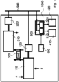
- a power plant 1000 in particular a combined cycle power plant, is arranged to generate electric power to be provided to an electric grid 900, the electric grid 900 being for example a national grid or a local grid (for example a microgrid or a nanogrid).
- the power plant 1000 includes a gas turbine 110, in particular a compressor compressing inlet air A, a combustor receiving a gas fuel F, also referred in the following as "primary fuel” and being typically natural gas, and a gas hydrogen H, also referred in the following as "secondary fuel", burning the fuel or fuels with an oxidant A, being typically air-fuel, and an expander expanding burned gas, the compressor and the expander having a first rotary shaft.
- the oxidant A is sucked by the compressor through a suction inlet of the compressor and the expanded burned gas are discharged through an exhaust outlet of the expander.
- the combustor may be premixed-type or diffusion type.
- the gas turbine is configured for selective burning, in particular so that, at some times its combustor burns only the primary fuel while at other times it burns both the primary fuel and the secondary fuel, i.e. hydrogen; only during very limited times (if any), it may burn only the secondary fuel, i.e. hydrogen.
- a first electric power generator 120 (that is included in the power plant 1000) is coupled to a first rotary shaft of the gas turbine 110 and generates a first electric power output. As shown in Fig. 1 , the electric power output of the first electric power generator 120 is arranged to be coupled to the electric grid 900, supplying electric power to the electric grid 900.
- an exhaust outlet of the gas turbine 110 in particular of its expander, discharges a hot exhaust gas flow still having heat capacity that can be exploited by a heat exchanger 300 that is included in the power plant 1000.
- the heat exchanger 300 is advantageously a heat recovery steam generator (HRSG) which is coupled to the exhaust outlet of the gas turbine 110 and it uses part of heat capacity of the exhausted gas to generate steam; therefore, the heat exchanger 300 may also be called "steam generator”.
- HRSG heat recovery steam generator
- the steam produced by HRSG is arranged to be fed to a steam turbine, in particular to a steam inlet of the steam turbine.
- the power plant 1000 additionally includes a steam turbine 210 having a second rotary shaft to which a second electric power generator 220 (that is included in the power plant 1000) is coupled; the second electric power generator 220 generates a second electric power output.
- the electric power output is arranged to be coupled to the electric grid 900, supplying electric power to the electric grid 900.
- the power plant 1000 includes at least a first electrolyzer 410 having a first electric power input arranged to be selectively coupled to the electric grid 900.
- the first electrolyzer 410 can be coupled/decoupled to/from the electric grid 900 and receive an electric input from the electric grid 900.
- the gas turbine 110 and/or the steam turbine 120 may be maintained permanently at the same or approximately the same operating conditions (preferably exactly or approximately optimal operating conditions) which means generating the same or approximately the same electric power by generators 120 and/or 220. It is to be noted that Fig.
- the one or more generators of the plant and the one or more electrolyzers of the plant may be directed or indirectly connected to the grid; for example, there may be internal electrical lines for diverting electric energy of the generators directly from the grid to the electrolyzers.
- the power plant 1000 has a first electric switch 510, located between the first electric input of the first electrolyzer 410 and the electric grid 900, and a control unit 600, coupled to the first electric switch 510 and arranged to control switching of the first electric switch 510, for example sending input to the first electric switch 510.
- the electric switch 510 is arranged to connect the first electrolyzer 410 and the electric grid 900 when it is in closed status and disconnect the first electrolyzer 410 and the electric grid 900 when it is in open status.
- control unit 600 is arranged to control switching of the first electric switch 510 according to at least one predetermined rule stored in the control unit 600.
- the power plant operator may have entered into agreements with the grid operator in such a way as to pre-define periods in which the electric switch 510 is closed and periods in which the electric switch 510 is open, i.e. respectively periods in which the electrolyzer 410 is coupled with the electric grid 900 and receive an electric input from the electric grid 900 and periods in which the electrolyzer 410 is not coupled to the electric grid 900.
- the electrolyzer 410 is coupled with the electric grid 900 when the electric energy demand of the grid from the power plant 1000 is reduced, in such a way that part of the electric power supplied by the power plant 1000 to the electric grid 900 is immediately and locally consumed by the electrolyzer 410.
- the power plant 1000 can be advantageously operated always in nominal conditions even if, in such conditions, the agreements with grid operator would have established a reduced electric power supply to the electric grid 900.
- control unit 600 is arranged to control switching of the first electric switch 510 according to at least one request received by the control unit 600.
- control unit 600 may receive from the grid operator or the plant operator an extemporaneous request of reducing electric power supply to the electric grid 900, due for example to a sudden decrease in electric energy demand.
- control unit 600 closes the electric switch 510 to couple the electrolyzer 410 with the electric grid 900 in such a way that the electrolyzer 410 immediately and locally consumes part of the electric power supplied by the power plant 1000 to the electric grid 900.
- the electric power input of the first electrolyzer 410 may be directly connected to the electric power generator 120, 220 output without being connected to the power grid 900 first.
- the electric switch 510 is located between the electric power generator 120, 220 output and the electric power input of the first electrolyzer 410.
- the power plant 1000 further comprises a second electrolyzer 420 having a second electric power input selectively coupled to the electric grid 900.
- the second electrolyzer 420 can be connected to the electric grid 900 and receive a second electric input from the electric grid 900.
- second electrolyzer 420 can be identical or different from first electrolyzer 420.
- the power plant 1000 has a second electric switch 520, located between the first electric input of the second electrolyzer 420 and the electric grid 900 and a control unit 600 coupled to the second electric switch 520 and arranged to control switching of the second electric switch 520, for example sending input to the second electric switch 520.
- the electric switch 210 is arranged to connect the second electrolyzer 420 and the electric grid 900 when it is in closed status and disconnect the second electrolyzer 420 and the electric grid 900 when it is in open status.
- control unit 600 is arranged to control switching of the second electric switch 520 according to at least one predetermined rule stored in the control unit 600.
- control unit 600 is arranged to control switching of the second electric switch 520 according to at least one request received by the control unit 600.
- control unit 600 coupled to the first electric switch 510 and the control unit 600 coupled to the second electric switch 520 may be the same control unit.
- control unit 600 is arranged to control both first electric switch 520 and second electric switch 520;
- Fig. 1 shows switch 510 and switch 520 as assembled in a single switching arrangement 500.
- control unit 600 can control the first electric switch 510 and the second electric switch 520 in different way and with different control logics, for example according to a predetermined rule stored in the control unit 600 or according to at least one request received by the control unit 600.
- the control unit 600 may close the first electric switch 510, coupling the first electrolyzer 410 with the electric grid 900, and may open the second electric switch 520 in such a way that the second electrolyzer 420 does not receive electric input from the electric grid 900.
- the electric power immediately consumed from the electric grid 900 by the power plant 1000, in particular, by the electrolyzers 410 and420 can be modulated at least in four different manners:
- the power plant 1000 may have additional electrolyzers with their respective electric switch that can be selectively coupled to the electric grid 900 by the control unit 600 to more finely modulate the electric power immediately and locally consumed by the power plant 1000.
- electrolysis performed by electrolyzers requires water as well as electric power, so the electrolyzers 410 and/or 420 are fluidly connected also to a water source that provides a water flow, in addition to the electric input provided by the electric grid 900.
- the water flow source may be external to the power plant 1000 and different depending on the plant configuration or the amount of water required.
- the power plant 1000 includes further a tank 800 for storing the hydrogen produced by the first electrolyzer 410 and by the second electrolyzer 420 (if present), and to be burned by the gas turbine 110 (when desired); hydrogen storage is preferably performed at ambient temperature (for example in the range between -10°C and +40°C); hydrogen storage is preferably performed at relatively low pressure, for example in the range between 30 bar and 100 bar; it is to be noted that pressure fluctuation in the tank 800 may be for example of 5-20 bar depending on the specific embodiment.
- the tank 800 may be very small; theoretically, its capacity could be null as the hydrogen might be used by the combustor as soon as it is produced by the electrolyzer(s).
- the tank is fluidly coupled only to the electrolyzer(s) for receiving hydrogen and only to the combustor of the turbine for transmitting hydrogen; such couplings may be through controlled valves.
- a control unit may be arranged to control the primary fuel flow and the secondary fuel flow to the a gas turbine 110 through e.g. one or more valves.
- control of the fuel flow or flows is performed according one or more predetermined rule stored in the control unit.
- This control unit may be further arranged to check a hydrogen level in the tank 800 (that may correspond to the hydrogen pressure in the tank); based on the hydrogen level, the control unit my decide to issue alarms and/or to regulate appropriate the fuel flow or flows.
- the tank 800 has a limited capacity. Its capacity is sufficient, typically exactly sufficient, for assuring operation of the gas turbine 110 for a predetermined time at a predetermined ratio of the secondary fuel and the primary fuel.
- the predetermined time is in the range 2-20 minutes; it is to be noted that the predetermined period of time may be chosen so to guarantee smooth operation of the combustor even if fluctuations of the primary fuel flow and of the secondary fuel flow occur and considering the speed of the flow control valves.
- the predetermined ratio is in the range 15-25 % in weight.
- the tank may have a capacity of approximately 25 m 3 - the pressure in the tank may vary between e.g. 30 bar and e.g. 40 bar.
- the power plant further comprises a heat exchanger 2720 for heating a water flow W and producing a heated water flow to be fed at least to the first electrolyzer 2410.
- the heat exchanger 2720 increases the efficiency of the electrolyzer and allows the use of medium-high temperature electrolyzer fed by the heated water flow produced by the heat exchanger 2720.
- the heated water flow W fed to the electrolyzer 2410 can be water flow, steam flow or a mixed water-steam flow depending on the type of electrolyzer used, for example an alkaline electrolyzer, a proton exchange membrane (PEM) electrolyzer or solid oxide electrolyzer cell (SOEC).
- PEM proton exchange membrane
- SOEC solid oxide electrolyzer cell
- the heat exchanger 2720 receives heat from the heat recovery steam generator 2300 that is used to heat the water flow W fed to the electrolyzer 2410.
- the heat received from the heat recovery steam generator 2300 is in the form of hot water flow, in particular a steam flow, for example a steam flow picked up between the HRSG evaporator 2320 and the HRSG superheater 2310.
- the power plant 1000 has a valve 2315, downstream the evaporator 2320, adapted to deviate part of the steam flow of the steam turbine engine, for example 1-2%, to the heat exchanger 2720.
- the heat exchanger 3720 receives heat from the heat recovery steam generator 3300, that is used to heat the water flow W fed to the electrolyzer 3410.
- the heat from the heat recovery steam generator 3300 is generated by exploiting the residual thermal capacity of exhausted gas EG before being released into the atmosphere. This is achieved by passing the water flow W to be fed to the electrolyzer 3410 in an economizer 3330 of the heat recovery steam generator 3300, just before releasing exhausted gas EG into the atmosphere. It is to be noted that, as shown in Fig. 3 , the heat exchanger 3720 may receive heat both by exploiting the residual thermal capacity of exhausted gas EG and by deviating part of the steam flow of the steam turbine engine.
- the electrolyzers 2410 and 3410 receiving electric energy from the grid 900 and heated water flow, produce as output an oxygen flow O and a hydrogen flow H by electrolysis. It has to be noted that both oxygen flow O and hydrogen flow H may not be pure oxygen or pure hydrogen flows; in particular, the hydrogen flow H can be a mixture of hydrogen and water (in particular steam) flow and/or a mixture of hydrogen and oxygen flow.
- the power plants 2000 and 3000 further comprise heat exchangers 2710 and 3710 and the hydrogen flow H produced at least by the electrolyzers 2410 and 3410 is cooled down by the heat exchangers 2710 and 3710.
- the heat exchangers 2710 and 3710 work also as a preheater of the water flow W by using the heat removed from the hydrogen flow H to heat the water flow W.
- the heat exchangers 2710 and 3710 are pre-heaters of the water flow W fed to the heat exchangers 2720 and 3720; in other word, the heat exchangers 2710 and 3710 are arranged to feed the heated water flow to the heat exchangers 2720 and 3720.
- the heat exchanger 3710 is between the economizer 3330 of the heat recovery steam generator 3300 and the heat exchanger 3720.
- the power plants 2000 and 3000 are arranged to feed the cooled hydrogen flow to the gas turbines 2110 and 3110.
- the gas turbines 2110 and 3110 are arranged to receive hydrogen flow H produced by the electrolyzers 2410 and 3410 and use it as fuel, in particular as "secondary fuel”.
- the hydrogen flow H is fed to mixers 2850 and 3850 wherein is mixed with a gaseous fuel F, i.e. the "primary fuel” that is typically natural gas, and then the hydrogen-fuel mixture is injected in the combustors 2111 and 3111 of the gas turbines 2110 and 3110.
- a gaseous fuel F i.e. the "primary fuel” that is typically natural gas
- the amount of the hydrogen flow H fed to the mixers 2850 and 3850 can be regulated by regulating valves 286 and 3860 and the amount of the gaseous fuel F fed to the mixers 2850 and 3850 can be regulated by regulating valves 2870 and 3870, so that the gas turbines 2110 and 3110 can be fueled by a mixture which can have different amount of hydrogen and fuel, for example can be fueled with a mixture of 70% fuel and 30% hydrogen or can be fueled up to 100% by the hydrogen flow H produced by the electrolyzers 2410 and 3410.
- the power plants 2000 and 3000 are premixed-flame combustion type.
- the technical teachings disclosed herein, in particular one or more of the technical features described with reference to Fig. 2 and Fig. 3 may be applied also to power plants wherein diffusion-flame combustion occurs.
- the power plants 2000 and 3000 comprise separators 2810 and 3810 to separate the hydrogen-water flow produced by the electrolyzers 2410 and 3410 to increase the purity level of hydrogen flow H received by the gas turbines 2110 and 3110.
- the power plants 2000 and 3000 comprise a deoxygenation stations 2820 and 3820 to separate the hydrogen-oxygen flow produced by the electrolyzers 2410 and 3410 to increase the purity level of hydrogen flow H received by the gas turbines 2110 and 3110.
- the power plants 2000 and 3000 comprise a station for removing water from hydrogen flow H, for example with a gravity separator of entrained liquid water from the electrolyzer or dehydration stations 2830 and 3830 to separate the water that may have remained even after the separators 2810 and 3810 to increase the purity level of hydrogen flow H received by gas turbines 2110 and 3110.
- the power plants 2000 and 3000 comprise also a tank 2800 and 3800 for storing hydrogen produced by the electrolyzers 2410 and 3410 (or further electrolyzers as shown e.g. in Fig. 1 ).
- these tanks are positioned upstream of the combustor 2111 and 3111 and downstream of the electrolyzers 2410 and 3410 and possibly one or more of the components 2710, 2810, 2820, 2830 shown in Fig. 2 and 3710, 3810, 3820, 3830 shown in Fig. 3 are fluidly coupled in-between.
- none of these components is a compressor, i.e. a machine arranged to increase the pressure of the hydrogen generated by the electrolyzer or electrolyzers.
- the coupling components are such that the pressure in the tank(s) is smaller (typically, only few bars smaller) than the pressure at the outlet of the electrolyzer(s); in other words, the coupling components introduce a (small) pressure drop.
- the coupling components are such that the pressure in the tank(s) is greater (typically, only few bars greater) than the pressure at the inlet of the combustor: in other words, the coupling components introduce a (small) pressure drop.
Landscapes
- Engineering & Computer Science (AREA)
- Chemical & Material Sciences (AREA)
- Combustion & Propulsion (AREA)
- Mechanical Engineering (AREA)
- General Engineering & Computer Science (AREA)
- Power Engineering (AREA)
- Electrolytic Production Of Non-Metals, Compounds, Apparatuses Therefor (AREA)
- Materials Engineering (AREA)
- Chemical Kinetics & Catalysis (AREA)
- Electrochemistry (AREA)
- Metallurgy (AREA)
- Organic Chemistry (AREA)
- Supply And Distribution Of Alternating Current (AREA)
- Engine Equipment That Uses Special Cycles (AREA)
- Inorganic Chemistry (AREA)
- Automation & Control Theory (AREA)
Claims (14)
- Kraftwerk (1000, 2000, 3000), das konfiguriert ist, um elektrische Leistung zu erzeugen, die an ein Stromnetz (900) bereitgestellt werden soll, das Kraftwerk umfassend:- eine Gasturbine (110, 2110, 3110), die eine erste Drehwelle aufweist und konfiguriert ist, um einen natürlichen Brennstoff und einen veredelten Brennstoff zu verbrennen,wobei die Gasturbine einen Abgasauslass aufweist,- einen ersten Stromerzeuger (120, 2120, 3120), der mit der ersten Drehwelle gekoppelt ist, wobei der erste Stromerzeuger einen ersten Stromausgang aufweist,- eine Dampfturbine (210, 2210, 3210), die eine zweiten Drehwelle aufweist, wobei die Dampfturbine einen Dampfeinlass aufweist,- einen zweiten Stromerzeuger (220, 2220, 3220), der mit der zweiten Drehwelle gekoppelt ist, wobei der zweite elektrische Stromerzeuger einen zweiten Stromausgang aufweist,- einen Dampferzeuger (300, 2300, 3300), der mit dem Abgasauslass gekoppelt und angeordnet ist, um Dampf dem Dampfeinlass zuzuführen,- einen ersten Elektrolyseur (410, 2410, 3410), der einen ersten Stromeingang aufweist, und- einen Tank (800, 2800, 3800) zum Speichern von Wasserstoff, der mindestens durch den ersten Elektrolyseur (410, 2410, 3410) produziert und durch die Gasturbine (110, 2110, 3110) verbrannt werden soll;wobei der erste Stromausgang des ersten Stromerzeugers (120, 2120, 3120) angeordnet ist, um an das Stromnetz (900) gekoppelt zu werden;wobei der zweite Stromausgang des zweiten Stromerzeugers (220, 2220, 3220) angeordnet ist, um an das Stromnetz (900) gekoppelt zu werden; wobei der erste Stromeingang des ersten Elektrolyseurs (410, 2410, 3410) angeordnet ist, um mit dem Stromnetz (900) selektiv gekoppelt zu werden;dadurch gekennzeichnet, dass der Tank (800, 2800, 3800) mit der Gasturbine (110, 2110, 3110) zur selektiven Verbrennen auch von Wasserstoff als veredelter Brennstoff, fluidisch gekoppelt ist.
- Kraftwerk (1000, 2000, 3000) nach Anspruch 1, ferner umfassend eine Steuereinheit (600), die angeordnet ist, um einen natürlichen Brennstoffstrom und einen veredelten Brennstoffstrom zu einer Gasturbine (110, 2110, 3110) zu steuern.
- Kraftwerk (1000, 2000, 3000) nach Anspruch 2, wobei die Steuereinheit (600) angeordnet ist, um einen Wasserstoffpegel in dem Tank (800, 2800, 3800) zu überprüfen.
- Kraftwerk (1000, 2000, 3000) nach Anspruch 1, wobei der Tank (800, 2800, 3800) eine begrenzte Kapazität aufweist und die begrenzte Kapazität ausreicht, um den Betrieb der Gasturbine (110, 2110, 3110) für eine vorherbestimmte Zeit bei einem vorherbestimmten Verhältnis des veredelten Brennstoffs und des natürlichen Brennstoffs sicherzustellen.
- Kraftwerk (1000, 2000, 3000) nach Anspruch 4, wobei die vorherbestimmte Zeit in dem Bereich von 2-20 Minuten liegt, und wobei das vorherbestimmte Verhältnis in dem Bereich von 15-25 Gew.-% liegt.
- Kraftwerk (1000, 2000, 3000) nach Anspruch 1, ferner umfassend:- einen ersten elektrischen Schalter (510), der zwischen dem ersten elektrischen Eingang des ersten Elektrolyseurs (410, 2410, 3410) und dem Stromnetz (900) gekoppelt ist, und- eine Steuereinheit (600), die mit dem ersten elektrischen Schalter (510) gekoppelt und angeordnet ist, um das Schalten des ersten elektrischen Schalters (510) zu steuern.
- Kraftwerk (1000) nach Anspruch 6, wobei die Steuereinheit (600) angeordnet ist, um das Schalten des ersten elektrischen Schalters (510) gemäß mindestens einer in der Steuereinheit (600) gespeicherten vorherbestimmten Regel zu steuern.
- Kraftwerk (1000) nach Anspruch 6, wobei die Steuereinheit (600) angeordnet ist, um das Schalten des ersten elektrischen Schalters (510) gemäß mindestens einer durch die Steuereinheit (600) empfangenen Anforderung zu steuern.
- Kraftwerk (1000) nach Anspruch 1, ferner umfassend:- einen zweiten Elektrolyseur (420), der einen zweiten elektrischen Stromeingang aufweist; wobei der zweite Stromeingang des zweiten Elektrolyseurs (420) angeordnet ist, um mit dem Stromnetz (900) selektiv gekoppelt zu werden.
- Kraftwerk (1000) nach Anspruch 9, ferner umfassend:- einen zweiten elektrischen Schalter (520), der zwischen dem zweiten elektrischen Eingang des zweiten Elektrolyseurs (420) und dem Stromnetz (900) gekoppelt ist, und- eine Steuereinheit (600), die mit dem zweiten elektrischen Schalter (520) gekoppelt und angeordnet ist, um das Schalten des zweiten elektrischen Schalters (520) zu steuern.
- Kraftwerk (1000) nach Anspruch 10, wobei die Steuereinheit (600) angeordnet ist, um das Schalten des zweiten elektrischen Schalters (520) gemäß mindestens einer in der Steuereinheit (600) gespeicherten vorherbestimmten Regel zu steuern.
- Kraftwerk (1000) nach Anspruch 10, wobei die Steuereinheit (600) angeordnet ist, um das Schalten des zweiten elektrischen Schalters (520) gemäß mindestens einer durch die Steuereinheit (600) empfangenen Anforderung zu steuern.
- Kraftwerk (2000, 3000) nach Anspruch 1, ferner umfassend:- einen ersten Wärmetauscher (2720, 3720) zum Erwärmen eines Wasserstroms (W) und Produzieren eines erwärmten Wasserstroms;wobei das Kraftwerk angeordnet ist, um den erwärmten Wasserstrom mindestens dem ersten Elektrolyseur (2410, 3410) zuzuführen.
- Kraftwerk (2000, 3000) nach Anspruch 13, wobei der erste Wärmetauscher (2720, 3720) angeordnet ist, um Abwärme von dem Dampferzeuger (2300, 3300) aufzunehmen.
Applications Claiming Priority (2)
| Application Number | Priority Date | Filing Date | Title |
|---|---|---|---|
| IT102021000004421A IT202100004421A1 (it) | 2021-02-25 | 2021-02-25 | Centrale elettrica per la generazione di energia elettrica per una rete elettrica comprendente un elettrolizzatore alimentato dalla rete elettrica |
| PCT/EP2022/025063 WO2022179753A1 (en) | 2021-02-25 | 2022-02-24 | Power plant for generating electric power for an electric grid comprising an electrolyzer powered by the electric grid |
Publications (2)
| Publication Number | Publication Date |
|---|---|
| EP4298324A1 EP4298324A1 (de) | 2024-01-03 |
| EP4298324B1 true EP4298324B1 (de) | 2025-02-12 |
Family
ID=75660284
Family Applications (1)
| Application Number | Title | Priority Date | Filing Date |
|---|---|---|---|
| EP22707617.1A Active EP4298324B1 (de) | 2021-02-25 | 2022-02-24 | Kraftwerk zur erzeugung elektrischer energie für ein stromnetz mit einem durch das stromnetz betriebenen elektrolyseur |
Country Status (10)
| Country | Link |
|---|---|
| US (1) | US12301001B2 (de) |
| EP (1) | EP4298324B1 (de) |
| JP (1) | JP7584670B2 (de) |
| KR (1) | KR102916140B1 (de) |
| CN (1) | CN116761929A (de) |
| AU (1) | AU2022225466B2 (de) |
| CA (1) | CA3209185A1 (de) |
| GB (1) | GB2619232B (de) |
| IT (1) | IT202100004421A1 (de) |
| WO (1) | WO2022179753A1 (de) |
Families Citing this family (3)
| Publication number | Priority date | Publication date | Assignee | Title |
|---|---|---|---|---|
| AU2024333388A1 (en) * | 2023-09-01 | 2026-02-26 | Volt Group Limited | An electrolyser system and method for operating an electrolyser system |
| US20250163848A1 (en) * | 2023-11-22 | 2025-05-22 | Gary Ross | Eco Barrier System |
| CN119853171B (zh) * | 2024-12-13 | 2025-11-18 | 哈尔滨工业大学 | 一种考虑电解槽动态安全约束的光-氢-储微电网调度方法 |
Family Cites Families (21)
| Publication number | Priority date | Publication date | Assignee | Title |
|---|---|---|---|---|
| US20050284154A1 (en) * | 2004-06-25 | 2005-12-29 | Peter Andrew M | System and method for storing hydrogen at cryogenic temperature |
| US7188478B2 (en) | 2004-09-13 | 2007-03-13 | General Electric Company | Power generation system and method of operating same |
| EP1804322B1 (de) | 2004-10-19 | 2011-12-14 | Central Research Institute of Electric Power Industry | Kombinierte stromerzeugungsgeräte |
| US20080121525A1 (en) * | 2005-10-11 | 2008-05-29 | Doland George J | Renewable Power Controller for Hydrogen Production |
| DE102009052047B4 (de) * | 2009-11-05 | 2014-01-16 | Airbus Operations Gmbh | Regeleinheit und Verfahren zum Regeln der Versorgung eines Fahrzeugs mit mehreren Treibstoffen |
| IT1399300B1 (it) * | 2010-04-19 | 2013-04-16 | Luminari | Impianto integrato a scarico zero per la produzione di elettricita' e idrogeno, con cattura della co2, recupero di calore e con disponibilita' di acqua da destinare al riscaldamento di edifici. |
| DE102010035487A1 (de) * | 2010-07-29 | 2012-02-23 | Linde Ag | Verfahren und Vorrichtung zur Stromspeicherung |
| DE102011014729A1 (de) * | 2011-03-22 | 2012-09-27 | Rwe Power Ag | Verfahren zur Ein- und Aufspeicherung von Energie sowie Gasturbinenkraftwerk |
| WO2013188479A1 (en) | 2012-06-13 | 2013-12-19 | Saudi Arabian Oil Company | Hydrogen production from an integrated electrolysis cell and hydrocarbon gasification reactor |
| US10436074B2 (en) * | 2013-01-24 | 2019-10-08 | Tascosa Advanced Service, Inc. | Combined brayton/rankine cycle gas and steam turbine generating system operated in two closed loops |
| AU2014209146B2 (en) | 2013-01-24 | 2017-08-24 | Edward HINDERS | Combined brayton/rankine cycle gas and steam turbine generating system operated in two closed loops |
| US20140203557A1 (en) * | 2013-01-24 | 2014-07-24 | General Electric Company | System and Method for Extending Minimum Turn Down Load of Combined Cycle Power Plant |
| EP2767697A1 (de) | 2013-02-19 | 2014-08-20 | Alstom Technology Ltd | Gasturbine mit Brennstoffzusammensetzungssteuerung |
| CN104481617B (zh) * | 2014-11-03 | 2015-12-02 | 东南大学 | 基于氧化还原反应的储能装置及其储能方法和发电方法 |
| DE102014225063A1 (de) * | 2014-12-05 | 2016-06-09 | Siemens Aktiengesellschaft | Kraftwerk |
| CN107093898A (zh) | 2017-04-11 | 2017-08-25 | 赫普热力发展有限公司 | 一种应用清洁能源发电电解制氢注入燃气管网的系统 |
| CN107100808B (zh) * | 2017-05-27 | 2019-06-14 | 集美大学 | 太阳能超临界二氧化碳循环发电耦合水蒸汽电解制氢系统 |
| US10344757B1 (en) * | 2018-01-19 | 2019-07-09 | Kennametal Inc. | Valve seats and valve assemblies for fluid end applications |
| JP7104591B2 (ja) * | 2018-09-07 | 2022-07-21 | 三菱重工業株式会社 | 水素製造システム |
| CN211474193U (zh) * | 2019-12-31 | 2020-09-11 | 湖南理工学院 | 一种热电氢多联供装置 |
| WO2021257333A1 (en) * | 2020-06-15 | 2021-12-23 | Bechtel Infrastructure and Power Corporation | Air energy storage with internal combustion engines |
-
2021
- 2021-02-25 IT IT102021000004421A patent/IT202100004421A1/it unknown
-
2022
- 2022-02-24 AU AU2022225466A patent/AU2022225466B2/en active Active
- 2022-02-24 JP JP2023545736A patent/JP7584670B2/ja active Active
- 2022-02-24 EP EP22707617.1A patent/EP4298324B1/de active Active
- 2022-02-24 KR KR1020237032004A patent/KR102916140B1/ko active Active
- 2022-02-24 GB GB2313999.1A patent/GB2619232B/en active Active
- 2022-02-24 CA CA3209185A patent/CA3209185A1/en active Pending
- 2022-02-24 WO PCT/EP2022/025063 patent/WO2022179753A1/en not_active Ceased
- 2022-02-24 US US18/547,238 patent/US12301001B2/en active Active
- 2022-02-24 CN CN202280011546.XA patent/CN116761929A/zh active Pending
Also Published As
| Publication number | Publication date |
|---|---|
| JP7584670B2 (ja) | 2024-11-15 |
| JP2024505896A (ja) | 2024-02-08 |
| WO2022179753A1 (en) | 2022-09-01 |
| IT202100004421A1 (it) | 2022-08-25 |
| US12301001B2 (en) | 2025-05-13 |
| US20240055943A1 (en) | 2024-02-15 |
| CA3209185A1 (en) | 2022-09-01 |
| KR102916140B1 (ko) | 2026-01-21 |
| GB202313999D0 (en) | 2023-10-25 |
| GB2619232A (en) | 2023-11-29 |
| EP4298324A1 (de) | 2024-01-03 |
| AU2022225466B2 (en) | 2024-12-12 |
| CN116761929A (zh) | 2023-09-15 |
| GB2619232B (en) | 2024-12-18 |
| KR20230145601A (ko) | 2023-10-17 |
| AU2022225466A1 (en) | 2023-09-07 |
Similar Documents
| Publication | Publication Date | Title |
|---|---|---|
| CN114704815B (zh) | 蒸汽储热系统 | |
| EP4298324B1 (de) | Kraftwerk zur erzeugung elektrischer energie für ein stromnetz mit einem durch das stromnetz betriebenen elektrolyseur | |
| US20070113562A1 (en) | Methods and apparatus for starting up combined cycle power systems | |
| US9631521B2 (en) | Method for operating a combined-cycle power plant | |
| Veyo et al. | Tubular SOFC hybrid power system status | |
| JPH0468446B2 (de) | ||
| CN114352369A (zh) | 氨分解制氢的燃气轮机-汽轮机联合发电系统及控制方法 | |
| Litzinger et al. | Comparative evaluation of SOFC/Gas turbine hybrid system options | |
| JP2004022230A (ja) | 燃料電池複合ガスタービンシステム | |
| Ubertini et al. | Assessment of an Ambient Pressure MCFC: External Heated GT Hybrid Plant with Steam Injection and Post‐Combustion | |
| CN113431651A (zh) | 一种低负荷一炉带两机的运行系统 | |
| CN115163306B (zh) | 一种可调峰储能的汽轮发电机组与燃氨燃气轮机联合系统 | |
| EP2542763B1 (de) | Energieerzeugungsanordnung und -verfahren | |
| JP7791323B2 (ja) | 環境からの液状水の取出しまたは環境への液状水の放出を伴わない間接的熱力学サイクルを備える原子炉を有する原子力熱電併給プラント | |
| US20260028934A1 (en) | Electrolysis energy recovery | |
| Azegami | MCFC/MGT hybrid generation system | |
| CN116838476B (zh) | 液态空气储能燃气轮机系统及方法 | |
| Lunghi et al. | Efficiency upgrading of an ambient pressure MCFC plant through the introduction of an indirect heated gas turbine | |
| CN223840399U (zh) | 一种燃煤火电厂锅炉带压气体掺烧的系统 | |
| JP2014160631A (ja) | 発電システム及び発電システムの運転方法 | |
| KR20240130203A (ko) | 신재생 에너지를 이용한 복합 화력 발전 장치 | |
| Azegami et al. | Development of a Pressurized MCFC/MGT Hybrid System | |
| WO2025132944A1 (en) | Multi modular system | |
| JP2004247116A (ja) | 燃料電池発電プラントの起動方法 | |
| CN120120083A (zh) | 一种联合机组运行方法及循环发电系统 |
Legal Events
| Date | Code | Title | Description |
|---|---|---|---|
| STAA | Information on the status of an ep patent application or granted ep patent |
Free format text: STATUS: UNKNOWN |
|
| STAA | Information on the status of an ep patent application or granted ep patent |
Free format text: STATUS: THE INTERNATIONAL PUBLICATION HAS BEEN MADE |
|
| PUAI | Public reference made under article 153(3) epc to a published international application that has entered the european phase |
Free format text: ORIGINAL CODE: 0009012 |
|
| STAA | Information on the status of an ep patent application or granted ep patent |
Free format text: STATUS: REQUEST FOR EXAMINATION WAS MADE |
|
| 17P | Request for examination filed |
Effective date: 20230905 |
|
| AK | Designated contracting states |
Kind code of ref document: A1 Designated state(s): AL AT BE BG CH CY CZ DE DK EE ES FI FR GB GR HR HU IE IS IT LI LT LU LV MC MK MT NL NO PL PT RO RS SE SI SK SM TR |
|
| DAV | Request for validation of the european patent (deleted) | ||
| DAX | Request for extension of the european patent (deleted) | ||
| GRAP | Despatch of communication of intention to grant a patent |
Free format text: ORIGINAL CODE: EPIDOSNIGR1 |
|
| STAA | Information on the status of an ep patent application or granted ep patent |
Free format text: STATUS: GRANT OF PATENT IS INTENDED |
|
| INTG | Intention to grant announced |
Effective date: 20240812 |
|
| GRAS | Grant fee paid |
Free format text: ORIGINAL CODE: EPIDOSNIGR3 |
|
| RAP3 | Party data changed (applicant data changed or rights of an application transferred) |
Owner name: NUOVO PIGNONE TECNOLOGIE - S.R.L. |
|
| GRAA | (expected) grant |
Free format text: ORIGINAL CODE: 0009210 |
|
| STAA | Information on the status of an ep patent application or granted ep patent |
Free format text: STATUS: THE PATENT HAS BEEN GRANTED |
|
| AK | Designated contracting states |
Kind code of ref document: B1 Designated state(s): AL AT BE BG CH CY CZ DE DK EE ES FI FR GB GR HR HU IE IS IT LI LT LU LV MC MK MT NL NO PL PT RO RS SE SI SK SM TR |
|
| REG | Reference to a national code |
Ref country code: GB Ref legal event code: FG4D |
|
| REG | Reference to a national code |
Ref country code: CH Ref legal event code: EP |
|
| REG | Reference to a national code |
Ref country code: DE Ref legal event code: R096 Ref document number: 602022010505 Country of ref document: DE |
|
| REG | Reference to a national code |
Ref country code: IE Ref legal event code: FG4D |
|
| REG | Reference to a national code |
Ref country code: SE Ref legal event code: TRGR |
|
| PGFP | Annual fee paid to national office [announced via postgrant information from national office to epo] |
Ref country code: AT Payment date: 20250417 Year of fee payment: 4 |
|
| REG | Reference to a national code |
Ref country code: NL Ref legal event code: MP Effective date: 20250212 |
|
| PG25 | Lapsed in a contracting state [announced via postgrant information from national office to epo] |
Ref country code: RS Free format text: LAPSE BECAUSE OF FAILURE TO SUBMIT A TRANSLATION OF THE DESCRIPTION OR TO PAY THE FEE WITHIN THE PRESCRIBED TIME-LIMIT Effective date: 20250512 |
|
| PG25 | Lapsed in a contracting state [announced via postgrant information from national office to epo] |
Ref country code: FI Free format text: LAPSE BECAUSE OF FAILURE TO SUBMIT A TRANSLATION OF THE DESCRIPTION OR TO PAY THE FEE WITHIN THE PRESCRIBED TIME-LIMIT Effective date: 20250212 |
|
| PG25 | Lapsed in a contracting state [announced via postgrant information from national office to epo] |
Ref country code: PL Free format text: LAPSE BECAUSE OF FAILURE TO SUBMIT A TRANSLATION OF THE DESCRIPTION OR TO PAY THE FEE WITHIN THE PRESCRIBED TIME-LIMIT Effective date: 20250212 |
|
| PG25 | Lapsed in a contracting state [announced via postgrant information from national office to epo] |
Ref country code: ES Free format text: LAPSE BECAUSE OF FAILURE TO SUBMIT A TRANSLATION OF THE DESCRIPTION OR TO PAY THE FEE WITHIN THE PRESCRIBED TIME-LIMIT Effective date: 20250212 |
|
| REG | Reference to a national code |
Ref country code: LT Ref legal event code: MG9D |
|
| PG25 | Lapsed in a contracting state [announced via postgrant information from national office to epo] |
Ref country code: IS Free format text: LAPSE BECAUSE OF FAILURE TO SUBMIT A TRANSLATION OF THE DESCRIPTION OR TO PAY THE FEE WITHIN THE PRESCRIBED TIME-LIMIT Effective date: 20250612 |
|
| PG25 | Lapsed in a contracting state [announced via postgrant information from national office to epo] |
Ref country code: NL Free format text: LAPSE BECAUSE OF FAILURE TO SUBMIT A TRANSLATION OF THE DESCRIPTION OR TO PAY THE FEE WITHIN THE PRESCRIBED TIME-LIMIT Effective date: 20250212 |
|
| PG25 | Lapsed in a contracting state [announced via postgrant information from national office to epo] |
Ref country code: HR Free format text: LAPSE BECAUSE OF FAILURE TO SUBMIT A TRANSLATION OF THE DESCRIPTION OR TO PAY THE FEE WITHIN THE PRESCRIBED TIME-LIMIT Effective date: 20250212 |
|
| PG25 | Lapsed in a contracting state [announced via postgrant information from national office to epo] |
Ref country code: PT Free format text: LAPSE BECAUSE OF FAILURE TO SUBMIT A TRANSLATION OF THE DESCRIPTION OR TO PAY THE FEE WITHIN THE PRESCRIBED TIME-LIMIT Effective date: 20250612 Ref country code: LV Free format text: LAPSE BECAUSE OF FAILURE TO SUBMIT A TRANSLATION OF THE DESCRIPTION OR TO PAY THE FEE WITHIN THE PRESCRIBED TIME-LIMIT Effective date: 20250212 |
|
| PG25 | Lapsed in a contracting state [announced via postgrant information from national office to epo] |
Ref country code: GR Free format text: LAPSE BECAUSE OF FAILURE TO SUBMIT A TRANSLATION OF THE DESCRIPTION OR TO PAY THE FEE WITHIN THE PRESCRIBED TIME-LIMIT Effective date: 20250513 Ref country code: BG Free format text: LAPSE BECAUSE OF FAILURE TO SUBMIT A TRANSLATION OF THE DESCRIPTION OR TO PAY THE FEE WITHIN THE PRESCRIBED TIME-LIMIT Effective date: 20250212 |
|
| P01 | Opt-out of the competence of the unified patent court (upc) registered |
Free format text: CASE NUMBER: APP_29050/2025 Effective date: 20250618 |
|
| PG25 | Lapsed in a contracting state [announced via postgrant information from national office to epo] |
Ref country code: AT Free format text: LAPSE BECAUSE OF FAILURE TO SUBMIT A TRANSLATION OF THE DESCRIPTION OR TO PAY THE FEE WITHIN THE PRESCRIBED TIME-LIMIT Effective date: 20250212 |
|
| REG | Reference to a national code |
Ref country code: AT Ref legal event code: MK05 Ref document number: 1766213 Country of ref document: AT Kind code of ref document: T Effective date: 20250212 |
|
| REG | Reference to a national code |
Ref country code: DE Ref legal event code: R119 Ref document number: 602022010505 Country of ref document: DE |
|
| REG | Reference to a national code |
Ref country code: CH Ref legal event code: PL |
|
| PG25 | Lapsed in a contracting state [announced via postgrant information from national office to epo] |
Ref country code: SM Free format text: LAPSE BECAUSE OF FAILURE TO SUBMIT A TRANSLATION OF THE DESCRIPTION OR TO PAY THE FEE WITHIN THE PRESCRIBED TIME-LIMIT Effective date: 20250212 |
|
| REG | Reference to a national code |
Ref country code: CH Ref legal event code: K11 Free format text: ST27 STATUS EVENT CODE: U-0-0-K10-K11 (AS PROVIDED BY THE NATIONAL OFFICE) Effective date: 20251009 Ref country code: CH Ref legal event code: U11 Free format text: ST27 STATUS EVENT CODE: U-0-0-U10-U11 (AS PROVIDED BY THE NATIONAL OFFICE) Effective date: 20251009 |
|
| PG25 | Lapsed in a contracting state [announced via postgrant information from national office to epo] |
Ref country code: DK Free format text: LAPSE BECAUSE OF FAILURE TO SUBMIT A TRANSLATION OF THE DESCRIPTION OR TO PAY THE FEE WITHIN THE PRESCRIBED TIME-LIMIT Effective date: 20250212 |
|
| PG25 | Lapsed in a contracting state [announced via postgrant information from national office to epo] |
Ref country code: LU Free format text: LAPSE BECAUSE OF NON-PAYMENT OF DUE FEES Effective date: 20250224 Ref country code: IT Free format text: LAPSE BECAUSE OF FAILURE TO SUBMIT A TRANSLATION OF THE DESCRIPTION OR TO PAY THE FEE WITHIN THE PRESCRIBED TIME-LIMIT Effective date: 20250212 |
|
| PG25 | Lapsed in a contracting state [announced via postgrant information from national office to epo] |
Ref country code: CH Free format text: LAPSE BECAUSE OF NON-PAYMENT OF DUE FEES Effective date: 20250228 |
|
| PG25 | Lapsed in a contracting state [announced via postgrant information from national office to epo] |
Ref country code: CZ Free format text: LAPSE BECAUSE OF FAILURE TO SUBMIT A TRANSLATION OF THE DESCRIPTION OR TO PAY THE FEE WITHIN THE PRESCRIBED TIME-LIMIT Effective date: 20250212 Ref country code: EE Free format text: LAPSE BECAUSE OF FAILURE TO SUBMIT A TRANSLATION OF THE DESCRIPTION OR TO PAY THE FEE WITHIN THE PRESCRIBED TIME-LIMIT Effective date: 20250212 |
|
| PG25 | Lapsed in a contracting state [announced via postgrant information from national office to epo] |
Ref country code: RO Free format text: LAPSE BECAUSE OF FAILURE TO SUBMIT A TRANSLATION OF THE DESCRIPTION OR TO PAY THE FEE WITHIN THE PRESCRIBED TIME-LIMIT Effective date: 20250212 |
|
| PG25 | Lapsed in a contracting state [announced via postgrant information from national office to epo] |
Ref country code: SK Free format text: LAPSE BECAUSE OF FAILURE TO SUBMIT A TRANSLATION OF THE DESCRIPTION OR TO PAY THE FEE WITHIN THE PRESCRIBED TIME-LIMIT Effective date: 20250212 |
|
| REG | Reference to a national code |
Ref country code: BE Ref legal event code: MM Effective date: 20250228 |
|
| PLBE | No opposition filed within time limit |
Free format text: ORIGINAL CODE: 0009261 |
|
| STAA | Information on the status of an ep patent application or granted ep patent |
Free format text: STATUS: NO OPPOSITION FILED WITHIN TIME LIMIT |
|
| PG25 | Lapsed in a contracting state [announced via postgrant information from national office to epo] |
Ref country code: MC Free format text: LAPSE BECAUSE OF FAILURE TO SUBMIT A TRANSLATION OF THE DESCRIPTION OR TO PAY THE FEE WITHIN THE PRESCRIBED TIME-LIMIT Effective date: 20250212 |
|
| REG | Reference to a national code |
Ref country code: CH Ref legal event code: L10 Free format text: ST27 STATUS EVENT CODE: U-0-0-L10-L00 (AS PROVIDED BY THE NATIONAL OFFICE) Effective date: 20251224 |
|
| PG25 | Lapsed in a contracting state [announced via postgrant information from national office to epo] |
Ref country code: DE Free format text: LAPSE BECAUSE OF NON-PAYMENT OF DUE FEES Effective date: 20250902 |
|
| PG25 | Lapsed in a contracting state [announced via postgrant information from national office to epo] |
Ref country code: FR Free format text: LAPSE BECAUSE OF NON-PAYMENT OF DUE FEES Effective date: 20250412 |
|
| PG25 | Lapsed in a contracting state [announced via postgrant information from national office to epo] |
Ref country code: BE Free format text: LAPSE BECAUSE OF NON-PAYMENT OF DUE FEES Effective date: 20250228 |
|
| PG25 | Lapsed in a contracting state [announced via postgrant information from national office to epo] |
Ref country code: CH Free format text: LAPSE BECAUSE OF NON-PAYMENT OF DUE FEES Effective date: 20250228 |
|
| PGRI | Patent reinstated in contracting state [announced from national office to epo] |
Ref country code: CH Effective date: 20251009 |
|
| PG25 | Lapsed in a contracting state [announced via postgrant information from national office to epo] |
Ref country code: IE Free format text: LAPSE BECAUSE OF NON-PAYMENT OF DUE FEES Effective date: 20250224 |
|
| 26N | No opposition filed |
Effective date: 20251113 |
|
| REG | Reference to a national code |
Ref country code: CH Ref legal event code: U11 Free format text: ST27 STATUS EVENT CODE: U-0-0-U10-U11 (AS PROVIDED BY THE NATIONAL OFFICE) Effective date: 20260301 |
|
| PGFP | Annual fee paid to national office [announced via postgrant information from national office to epo] |
Ref country code: SE Payment date: 20260121 Year of fee payment: 5 |
|
| PGFP | Annual fee paid to national office [announced via postgrant information from national office to epo] |
Ref country code: GB Payment date: 20260121 Year of fee payment: 5 |
|
| PGFP | Annual fee paid to national office [announced via postgrant information from national office to epo] |
Ref country code: NO Payment date: 20260320 Year of fee payment: 5 |
|
| PGFP | Annual fee paid to national office [announced via postgrant information from national office to epo] |
Ref country code: CH Payment date: 20260301 Year of fee payment: 5 |