EP4297170A1 - Battery module assembly apparatus having enhanced productivity and assembly method using same - Google Patents
Battery module assembly apparatus having enhanced productivity and assembly method using same Download PDFInfo
- Publication number
- EP4297170A1 EP4297170A1 EP22842362.0A EP22842362A EP4297170A1 EP 4297170 A1 EP4297170 A1 EP 4297170A1 EP 22842362 A EP22842362 A EP 22842362A EP 4297170 A1 EP4297170 A1 EP 4297170A1
- Authority
- EP
- European Patent Office
- Prior art keywords
- battery module
- unit
- battery
- bonding
- module
- Prior art date
- Legal status (The legal status is an assumption and is not a legal conclusion. Google has not performed a legal analysis and makes no representation as to the accuracy of the status listed.)
- Granted
Links
Images





Classifications
-
- H—ELECTRICITY
- H01—ELECTRIC ELEMENTS
- H01M—PROCESSES OR MEANS, e.g. BATTERIES, FOR THE DIRECT CONVERSION OF CHEMICAL ENERGY INTO ELECTRICAL ENERGY
- H01M10/00—Secondary cells; Manufacture thereof
- H01M10/05—Accumulators with non-aqueous electrolyte
- H01M10/052—Li-accumulators
- H01M10/0525—Rocking-chair batteries, i.e. batteries with lithium insertion or intercalation in both electrodes; Lithium-ion batteries
-
- H—ELECTRICITY
- H01—ELECTRIC ELEMENTS
- H01M—PROCESSES OR MEANS, e.g. BATTERIES, FOR THE DIRECT CONVERSION OF CHEMICAL ENERGY INTO ELECTRICAL ENERGY
- H01M50/00—Constructional details or processes of manufacture of the non-active parts of electrochemical cells other than fuel cells, e.g. hybrid cells
- H01M50/50—Current conducting connections for cells or batteries
- H01M50/502—Interconnectors for connecting terminals of adjacent batteries; Interconnectors for connecting cells outside a battery casing
- H01M50/514—Methods for interconnecting adjacent batteries or cells
- H01M50/516—Methods for interconnecting adjacent batteries or cells by welding, soldering or brazing
-
- B—PERFORMING OPERATIONS; TRANSPORTING
- B23—MACHINE TOOLS; METAL-WORKING NOT OTHERWISE PROVIDED FOR
- B23K—SOLDERING OR UNSOLDERING; WELDING; CLADDING OR PLATING BY SOLDERING OR WELDING; CUTTING BY APPLYING HEAT LOCALLY, e.g. FLAME CUTTING; WORKING BY LASER BEAM
- B23K9/00—Arc welding or cutting
- B23K9/0026—Arc welding or cutting specially adapted for particular articles or work
-
- G—PHYSICS
- G01—MEASURING; TESTING
- G01N—INVESTIGATING OR ANALYSING MATERIALS BY DETERMINING THEIR CHEMICAL OR PHYSICAL PROPERTIES
- G01N21/00—Investigating or analysing materials by the use of optical means, i.e. using sub-millimetre waves, infrared, visible or ultraviolet light
- G01N21/84—Systems specially adapted for particular applications
- G01N21/88—Investigating the presence of flaws or contamination
- G01N21/8851—Scan or image signal processing specially adapted therefor, e.g. for scan signal adjustment, for detecting different kinds of defects, for compensating for structures, markings, edges
-
- H—ELECTRICITY
- H01—ELECTRIC ELEMENTS
- H01M—PROCESSES OR MEANS, e.g. BATTERIES, FOR THE DIRECT CONVERSION OF CHEMICAL ENERGY INTO ELECTRICAL ENERGY
- H01M10/00—Secondary cells; Manufacture thereof
- H01M10/04—Construction or manufacture in general
- H01M10/0404—Machines for assembling batteries
-
- H—ELECTRICITY
- H01—ELECTRIC ELEMENTS
- H01M—PROCESSES OR MEANS, e.g. BATTERIES, FOR THE DIRECT CONVERSION OF CHEMICAL ENERGY INTO ELECTRICAL ENERGY
- H01M50/00—Constructional details or processes of manufacture of the non-active parts of electrochemical cells other than fuel cells, e.g. hybrid cells
- H01M50/10—Primary casings; Jackets or wrappings
- H01M50/102—Primary casings; Jackets or wrappings characterised by their shape or physical structure
- H01M50/107—Primary casings; Jackets or wrappings characterised by their shape or physical structure having curved cross-section, e.g. round or elliptic
-
- H—ELECTRICITY
- H01—ELECTRIC ELEMENTS
- H01M—PROCESSES OR MEANS, e.g. BATTERIES, FOR THE DIRECT CONVERSION OF CHEMICAL ENERGY INTO ELECTRICAL ENERGY
- H01M50/00—Constructional details or processes of manufacture of the non-active parts of electrochemical cells other than fuel cells, e.g. hybrid cells
- H01M50/20—Mountings; Secondary casings or frames; Racks, modules or packs; Suspension devices; Shock absorbers; Transport or carrying devices; Holders
-
- H—ELECTRICITY
- H01—ELECTRIC ELEMENTS
- H01M—PROCESSES OR MEANS, e.g. BATTERIES, FOR THE DIRECT CONVERSION OF CHEMICAL ENERGY INTO ELECTRICAL ENERGY
- H01M50/00—Constructional details or processes of manufacture of the non-active parts of electrochemical cells other than fuel cells, e.g. hybrid cells
- H01M50/20—Mountings; Secondary casings or frames; Racks, modules or packs; Suspension devices; Shock absorbers; Transport or carrying devices; Holders
- H01M50/204—Racks, modules or packs for multiple batteries or multiple cells
- H01M50/207—Racks, modules or packs for multiple batteries or multiple cells characterised by their shape
- H01M50/213—Racks, modules or packs for multiple batteries or multiple cells characterised by their shape adapted for cells having curved cross-section, e.g. round or elliptic
-
- H—ELECTRICITY
- H01—ELECTRIC ELEMENTS
- H01M—PROCESSES OR MEANS, e.g. BATTERIES, FOR THE DIRECT CONVERSION OF CHEMICAL ENERGY INTO ELECTRICAL ENERGY
- H01M50/00—Constructional details or processes of manufacture of the non-active parts of electrochemical cells other than fuel cells, e.g. hybrid cells
- H01M50/20—Mountings; Secondary casings or frames; Racks, modules or packs; Suspension devices; Shock absorbers; Transport or carrying devices; Holders
- H01M50/244—Secondary casings; Racks; Suspension devices; Carrying devices; Holders characterised by their mounting method
-
- Y—GENERAL TAGGING OF NEW TECHNOLOGICAL DEVELOPMENTS; GENERAL TAGGING OF CROSS-SECTIONAL TECHNOLOGIES SPANNING OVER SEVERAL SECTIONS OF THE IPC; TECHNICAL SUBJECTS COVERED BY FORMER USPC CROSS-REFERENCE ART COLLECTIONS [XRACs] AND DIGESTS
- Y02—TECHNOLOGIES OR APPLICATIONS FOR MITIGATION OR ADAPTATION AGAINST CLIMATE CHANGE
- Y02E—REDUCTION OF GREENHOUSE GAS [GHG] EMISSIONS, RELATED TO ENERGY GENERATION, TRANSMISSION OR DISTRIBUTION
- Y02E60/00—Enabling technologies; Technologies with a potential or indirect contribution to GHG emissions mitigation
- Y02E60/10—Energy storage using batteries
-
- Y—GENERAL TAGGING OF NEW TECHNOLOGICAL DEVELOPMENTS; GENERAL TAGGING OF CROSS-SECTIONAL TECHNOLOGIES SPANNING OVER SEVERAL SECTIONS OF THE IPC; TECHNICAL SUBJECTS COVERED BY FORMER USPC CROSS-REFERENCE ART COLLECTIONS [XRACs] AND DIGESTS
- Y02—TECHNOLOGIES OR APPLICATIONS FOR MITIGATION OR ADAPTATION AGAINST CLIMATE CHANGE
- Y02P—CLIMATE CHANGE MITIGATION TECHNOLOGIES IN THE PRODUCTION OR PROCESSING OF GOODS
- Y02P70/00—Climate change mitigation technologies in the production process for final industrial or consumer products
- Y02P70/50—Manufacturing or production processes characterised by the final manufactured product
Definitions
- a lithium ion battery there are a lithium ion battery, a lithium polymer battery, a nickel-cadmium battery, a nickel-hydride battery, and a nickel-zinc battery as secondary batteries.
- the operating voltage of a unit secondary battery cell i.e., a unit battery cell, is about 2.5 V to 4.5 V.
- a plurality of battery cells may be connected to each other in series to constitute a battery module.
- a plurality of battery modules may be connected to each other in series or in parallel to constitute a battery pack depending on required charge and discharge capacities.
- the present invention has been made in view of the above problems, and it is an object of the present invention to provide a battery module assembly apparatus with improved productivity capable of accurately scanning the positions of a module carrier and a plurality of battery cells received in the module carrier such that the battery cells are bonded to a busbar at predetermined positions and an assembly method using the same.
- a battery module assembly apparatus to accomplish the above objects includes a transfer unit (200) configured to move a battery module (100) having a cylindrical battery cell (120) received therein seated in a module carrier (220); a vision unit (300) configured to check position information of the battery module (100) and the module carrier (220); and
- At least one bonding unit (400) each configured to electrically connect an electrode of the cylindrical battery cell (120) received in the battery module (100) to a busbar (130), wherein the battery module assembly apparatus is configured to transmit the position information checked from the vision unit (300) to the bonding unit (400).
- the transfer unit (200) may include a height adjustment portion (240) configured to move the battery module (100) and the module carrier (220) located at an upper end thereof upwards and downwards in a vertical direction.
- the transfer unit (200) may be disposed separately for each zone and may be independently operated in each zone.
- the transfer unit (300) may be movable forwards and rearwards or leftwards and rightwards.
- the module carrier (220) may include a stationary guard and a moving guard, and the moving guard may be configured to move forwards and rearwards or leftwards and rightwards to fix the battery module received in the module carrier.
- the battery module assembly apparatus may include at least one datum portion (230) provided at an outer side of the stationary guard.
- the vision unit (300) may be configured to scan the marker for position identification, the position of the electrode of the cylindrical battery cell (120), and the position of the busbar provided at the battery module (100).
- the bonding unit (400) and the vision unit (300) may be disposed on the transfer unit (200), the transfer unit being arranged in a straight line, and the battery module assembly apparatus further including an additional bonding unit provided on the transfer unit and diverging from the vision unit (300).
- the bonding unit (400) may include a separate bonding vision portion for position identification when electrically connecting the electrode to the busbar (130).
- step (s1) moving a moving guard of the module carrier (200) to fix the battery module (100) to the module carrier (220) may be further performed.
- the present invention provides a battery pack including a battery module obtained by the assembly method.
- a vision unit for precise scanning and a separate bonding vision portion for welding are used, whereby it is possible to improve bonding precision.
- one vision unit and a plurality of bonding units are provided, whereby it is possible to reduce battery module production time, and therefore it is possible to improve productivity.
- FIG. 2 is a plan view showing a battery module according to a first embodiment of the present invention
- FIG. 3 is a sectional view of a battery cell according to a first embodiment of the present invention.
- the battery module 100 includes a module case 110, a cylindrical battery cell 120, and a busbar 130.
- the electrode assembly 121 is manufactured by sequentially stacking a positive electrode 121(a), a negative electrode 121(b), and a separator 121(c) and winding the same in a round shape.
- a cylindrical center pin 125 is inserted into a hollow core portion 124 formed in a central region of the electrode assembly 121.
- the center pin 125 is made of a metal material so as to have a predetermined strength.
- the center pin 125 serves as a path that discharges gas generated due to internal reaction during charging and discharging or during operation while fixing and supporting the electrode assembly 121.
- a positive electrode terminal 123(a) is formed on a central region of an upper end of the cap assembly 123 in a protruding form, and the remaining region of the metal can 122 forms a negative electrode terminal 123(b).
- cylindrical battery cell 120 is not particularly restricted as long as the positive electrode terminal 123(a) and the negative electrode terminal 123(b) are exposed or protrude from the upper end of the cap assembly 123.
- the busbars 130 which are configured to connect the plurality of cylindrical battery cells 120 to each other in series or in parallel, are located side by side in a state of being spaced apart from the cylindrical battery cells 120 by a predetermined distance.
- the busbar 130 shown in FIG. 2 has a very simple shape, and the busbar 130 is basically provided with a plurality of coupling portions capable of being coupled to the electrode terminals of the plurality of cylindrical battery cells 120 in order to connect the cylindrical battery cells 120 to each other in series or in parallel, and the coupling portions are connected for series or parallel connection.
- the coupling portions of the busbar 130, which are electrically connected to the cylindrical battery cells 120, are omitted from FIG. 2 , and the busbar 130 may be variously deformed as needed.
- the battery module according to the present invention may include a cover case (not shown).
- a plurality of protrusions having a predetermined height is formed so as to protect the cylindrical battery cells 120 from external impact from above.
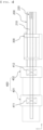
- FIG. 4 is a plan view of a battery module assembly apparatus according to a first embodiment of the present invention
- FIG. 5 is a front view of the battery module assembly apparatus according to the first embodiment of the present invention
- FIG. 6 is a perspective view of a module carrier having the battery module according to the first embodiment of the present invention received therein.
- the battery module assembly apparatus may include a transfer unit 200, a vision unit 300, and a bonding unit 400.
- the transfer unit 200, a vision unit 300, and a bonding unit 400 may be disposed in a straight line. In this case, it is possible to minimize shaking of the battery module during transfer thereof, which is advantageous to improvement in production quality.
- the transfer unit 200 which is configured to transfer the battery module 100 in a process flow direction, includes a conveyor 210 configured to provide a movement path of the battery module 100 and a module carrier 220 mounted to an upper end of the conveyor 210.
- the module carrier 220 may be detachably attached to the upper end of the conveyor 210, and may be formed in the shape of a rectangular parallelepiped in which a receiving portion capable of receiving the battery module 100 is formed by a vertically disposed guard.
- the module carrier will be described below in detail with reference to FIG. 6 .
- the conveyor 210 serves to transfer the battery module 100 from a front end of the battery module assembly apparatus to a discharge portion (not shown) of a bonding unit 400 located at a rear end, and is formed so as to extend over the entirety of the apparatus.
- the conveyor 210 may be provided separately for each zone in the vision unit 300 and the bonding unit 400, and may be independently operated in each zone.
- the conveyors 210 located in a state of being divided for each zone may be connected to each other in order to continuously transfer the battery module located at an upper end thereof.
- the conveyor 210 may be connected to a driving unit (not shown) for driving the conveyor, and the driving unit may be connected to a controller (not shown) for automatic control.
- a height adjustment portion 240 may be located at a lower end of the conveyor 210, and the height adjustment portion 240 may move the conveyor 210 located at an upper end thereof upwards or downwards in a vertical direction (z-axis direction).
- the upward movement height of the conveyor 210 by the height adjustment portion 240 in the vertical direction may be 300 mm or less. Consequently, it is possible to adjust the height adjustment portion 240 upwards and downwards depending on the specifications of the battery cell 120 located in the battery module 100 located at the upper end of the conveyor 210, i.e., the height of the battery cell, whereby it is possible to adjust the vertical position of the battery cell 120 at the bonding unit 400, which is advantageous to efficient bonding work.
- the height adjustment portion 240 may be connected to a controller (not shown), and may be moved upwards or downwards by the controller.
- FIG. 6 is a perspective view of the module carrier having the battery module according to the first embodiment of the present invention received therein.
- the first moving guard 223 and the second moving guard 224 may be rotated 90 degrees, whereby the wide surfaces thereof may be located vertically from a horizontal state. Subsequently, the first moving guard 223 and the second moving guard 224 may move in the direction toward the battery module 100 received in the receiving portion of the module carrier 220 so as to be located in tight contact with the battery module 100 such that the battery module 100 is fixed in the module carrier 220.
- At least one datum portion 230 may be located at a surface of the second stationary guard 222 opposite the surface thereof that faces the receiving portion configured to receive the battery module 100, and an L-shaped marker may be located at an upper surface of the datum portion 230.
- the datum portion 230 may be located in the middle between a pair of battery cell columns located parallel to the first stationary guard 221 based on the pair of battery cell columns.
- the battery module 100 may be partitioned into zones based on the pair of battery cell columns located parallel to the first stationary guard 221. In FIG.
- a first module zone 101, a second module zone 102, and a third module zone 103 are shown as being located in a direction distant from the first stationary guard 221, which, however, is merely an example in the present invention. It is obvious that the battery module is not partitioned into the above zones.
- the vision unit 300 will be described in detail with reference back to FIGS. 4 and 5 .
- the vision unit 300 may scan an upper surface of the module carrier 220 that receives the battery module 100 transferred by the conveyor 210 and may transmit the scanning result to the bonding unit 500 at the rear end.
- the vision unit 300 may include a vision camera (not shown) and an illuminator (not shown) located at a lower end of the vision camera.
- the vision camera scans the position at which the module case 110 is disposed and the position of the battery cell 120 received in the module case 110 based on the L-shaped marker on the datum portion 230 of the module carrier 220.
- the vision camera may scan the L-shaped marker on the datum portion 230 and the position of each of the battery cells 120 included in the battery cell columns disposed parallel to the first stationary guard 221 at opposite sides of the datum portion 230. More specifically, the vision camera may scan the L-shaped marker on the datum portion 230, the positions of a positive electrode and a negative electrode of the battery cell 120, and the relative position between the positive electrode and the negative electrode of each battery cell 120 from the L-shaped marker on the datum portion 230.
- Scan information obtained by the vision unit 300 is transmitted to the bonding unit 400 at the rear end.
- the bonding unit 400 is movable in leftward-rightward and forward-rearward directions, and performs wire bonding work for each module zone.
- the battery module assembly apparatus includes one vision unit 300 and two bonding units 400, i.e., a first bonding unit 401 and a second bonding unit 402.
- the vision unit 300 scans an upper surface of a module carrier 220 that receives a first battery module 100, the module carrier 220 that receives the first battery module 100 is moved rearwards, a module carrier 220 that receives a second battery module 100 is supplied, an upper surface of the module carrier that receives the second battery module 100 is scanned, and the module carrier that receives the second battery module is moved rearwards.
- the module carrier 220 that receives the first battery module 100 is transferred to the first bonding unit 401 at the rear end, scan information of the upper surface of the module carrier 220 that receives the first battery module 100 scanned by the vision unit 300 is transmitted to the first bonding unit 401.
- the module carrier 220 that receives the second battery module 100 is transferred to the second bonding unit 402 at the rear end, scan information of the upper surface of the module carrier 220 that receives the second battery module 100 scanned by the vision unit 300 is transmitted to the second bonding unit 402.
- the first bonding unit 401 performs wire bonding work using photograph information obtained by a first camera 411 and the scan information received from the vision unit 300 with respect to the module carrier 220 that receives the first battery module 100 transferred thereto
- the second bonding unit 402 performs wire bonding work using photograph information obtained by a second camera 412 and the scan information received from the vision unit 300 with respect to the module carrier 220 that receives the first battery module 100 transferred thereto. Since bonding of the battery module 100 is continuously performed through the above work, it is possible to improve productivity of the battery module.
- FIG. 7 is a plan view of a battery module assembly apparatus according to a second embodiment of the present invention.
- the third bonding unit 1403 and the fourth bonding unit 1404 check and analyze a datum portion of the module carrier, the position of a battery cell, and the relative position between a positive electrode and a negative electrode of the battery cell using scan information received from a vision unit 1300 and information obtained by a third camera 1413 and a fourth camera 1414 disposed respectively at the third bonding unit 1403 and the fourth bonding unit 1404, and then perform wire bonding.
- the module carrier 1220 that receives the battery module scanned by the vision unit 1300 is transferred to a production line on which the third bonding unit 1403 and the fourth bonding unit 1404 are located by the parallel transfer unit 1420.
- the parallel transfer unit 1420 may be located perpendicular to a transfer unit 1200 at which the first bonding unit 1401 and the second bonding unit 1402 are located, and may be configured in a conveyor structure. Between the transfer unit 120 and the parallel transfer unit 1420 and between the parallel transfer unit 1420 and a transfer unit (not shown) at which the third bonding unit 1403 and the fourth bonding unit 1404 are located, a moving means capable of minimizing shaking of the battery module and the battery cell received in the module carrier 1220 located at the upper end thereof may be further provided.
- the bonding units are disposed in series and in parallel, as described above, it is possible to improve overall productivity of the battery module assembly process.
- An assembly method using a battery module assembly apparatus may include (s1) a step of seating a battery module 100 having a battery cell 120 received therein in a module carrier 220, (s2) a step of moving the module carrier using a transfer unit 200, (s3) a step of scanning a datum portion 230 and an upper end surface of the battery module 100 using a vision unit 300, and (s4) a step of connecting an electrode of the battery cell 120 received in the battery module 100 to a busbar by wire bonding.
- step (s1) a step of moving a moving guard of the module carrier 200 to fix the battery module 100 to the module carrier 220 may be further performed.
- step (s3) the upper end surface of the module carrier 220 that receives continuously supplied battery modules 100 may be scanned by the vision unit 300, and the battery modules may be supplied to different bonding units.
- One or more battery modules each of which is assembled using the battery module assembly method according to the present invention, may be clustered to constitute a battery pack.
Landscapes
- Chemical & Material Sciences (AREA)
- Chemical Kinetics & Catalysis (AREA)
- Electrochemistry (AREA)
- General Chemical & Material Sciences (AREA)
- Engineering & Computer Science (AREA)
- Physics & Mathematics (AREA)
- Manufacturing & Machinery (AREA)
- Health & Medical Sciences (AREA)
- General Health & Medical Sciences (AREA)
- Signal Processing (AREA)
- Pathology (AREA)
- Life Sciences & Earth Sciences (AREA)
- Analytical Chemistry (AREA)
- Biochemistry (AREA)
- Computer Vision & Pattern Recognition (AREA)
- General Physics & Mathematics (AREA)
- Immunology (AREA)
- Mechanical Engineering (AREA)
- Plasma & Fusion (AREA)
- Materials Engineering (AREA)
- Battery Mounting, Suspending (AREA)
- Connection Of Batteries Or Terminals (AREA)
Abstract
Description
- This application claims the benefit of priority to
Korean Patent Application No. 2021-0092662 filed on July 15, 2021 - The present invention relates to a battery module assembly apparatus with improved productivity and an assembly method using the same. More particularly, the present invention relates to a battery module assembly apparatus including two or more bonding units and capable of individually supplying a battery module to each bonding unit to electrically connect a battery cell and a busbar to each other and an assembly method using the same.
- Secondary batteries are generally used in an electric vehicle (EV) or a hybrid electric vehicle (HEV), which is driven by an electric driving source, as well as portable devices. Secondary batteries have attracted attention as a new energy source capable of enhancing environmental friendliness and energy efficiency since the secondary batteries generate no byproducts as the result of using energy in addition to the primary advantage of remarkably reducing the use of fossil fuels.
- There are a lithium ion battery, a lithium polymer battery, a nickel-cadmium battery, a nickel-hydride battery, and a nickel-zinc battery as secondary batteries. The operating voltage of a unit secondary battery cell, i.e., a unit battery cell, is about 2.5 V to 4.5 V. When output voltage higher than the above operating voltage is required, therefore, a plurality of battery cells may be connected to each other in series to constitute a battery module. In addition, a plurality of battery modules may be connected to each other in series or in parallel to constitute a battery pack depending on required charge and discharge capacities.
- In order to satisfy required output voltage, a plurality of cylindrical battery cells is received in a battery module, and the battery cells are electrically connected to each other via a busbar. For a cylindrical battery cell, however, a positive electrode and a negative electrode are located very close to each other and the area of a part having each polarity is small, whereby it is not easy to connect the cylindrical battery cell to the busbar.
- In connection therewith,
FIG. 1 is a schematic view showing a conventional battery cell bonding apparatus. Referring toFIG. 1 , a battery module assembly apparatus includes a supply unit configured to supply abattery module 10 to the apparatus, atransfer unit 20 configured to move the supplied battery module to a work position, avision unit 30 including a vision type camera configured to scan the battery module transferred, and awelding unit 40 configured to perform bonding work with respect to the battery module. The battery module transferred by the transfer unit is scanned through the vision type camera to set coordinates thereof, and the welding unit is moved to the work position based on this information in order to perform bonding work. In the above conventional art, one welding unit and one vision type camera are basically provided, and the welding unit performs bonding work. The battery module assembly apparatus according toFIG. 1 has disadvantages in that 1) in the initial stage, coordinates are set using only one vision unit for scanning, whereby a function of correcting errors at the time of actual welding is not provided, 2) work is performed in a line, whereby productivity is low, and 3) it is difficult to assembly battery modules having various dimensions. -
Patent Document 1 discloses wire bonder logistics facilities configured such that magazines are continuously provided to a wire bonder using a magazine transfer robot, whereby the wire bonder continuously performs work without downtime, and therefore work efficiency is improved. Specifically, a magazine transfer robot apparatus including a plurality of wire bonders, a stocker having a magazine buffer configured to store a magazine to be provided to the wire bonders, and a gripper configured to supply or discharge the magazine to the stocker or the wire bonders while gripping the magazine is disclosed. -
Patent Document 2 discloses a wire bonding apparatus capable of being connected in line without necessity for a separate substrate transfer apparatus. Specifically, a material transfer unit configured to transfer a substrate between the wire bonding apparatuses and a sensor located above the material transfer unit to sense whether wire bonding has been performed with respect to a substrate introduced into the wire bonding apparatus are disclosed. -
Patent Document 1 is technology in which the direction of an arrow formed at an upper part of the magazine is identified using a vision device, and when the direction of the arrow is different from a predetermined direction, the magazine is rotated 180 degrees using a motor of a rotating device in order to perform bonding, andPatent Document 2 is technology in which, after wire bonding, a substrate on which wire bonding has been completed and a substrate on which wire bonding has not been completed are distinguished from each other using a vision device. - However, a battery module assembly apparatus capable of simultaneously performing wire bonding work with respect to a plurality of battery modules, thereby improving productivity, and performing wire bonding with respect to battery modules including battery cells having different dimensions, which are recognized as important problems in the present invention, has not yet been proposed.
-
Korean Registered Patent Publication No. 10-1824069 Patent Document 1") -
Korean Patent Application Publication No. 10-2007-0094259 Patent Document 2") - The present invention has been made in view of the above problems, and it is an object of the present invention to provide a battery module assembly apparatus with improved productivity capable of accurately scanning the positions of a module carrier and a plurality of battery cells received in the module carrier such that the battery cells are bonded to a busbar at predetermined positions and an assembly method using the same.
- It is another object of the present invention to provide a battery module assembly apparatus including a plurality of bonding units, wherein bonding work by the bonding units and scanning work by a vision unit are continuously performed, whereby productivity is improved, and an assembly method using the same.
- It is a further object of the present invention to provide a battery module assembly apparatus having a height adjustment portion capable of moving the module carrier upwards and downwards, whereby the battery module assembly apparatus is applicable to battery modules constituted by cylindrical battery cells having various heights, and an assembly method using the same.
- A battery module assembly apparatus according to the present invention to accomplish the above objects includes a transfer unit (200) configured to move a battery module (100) having a cylindrical battery cell (120) received therein seated in a module carrier (220); a vision unit (300) configured to check position information of the battery module (100) and the module carrier (220); and
- at least one bonding unit (400) each configured to electrically connect an electrode of the cylindrical battery cell (120) received in the battery module (100) to a busbar (130), wherein the battery module assembly apparatus is configured to transmit the position information checked from the vision unit (300) to the bonding unit (400).
- The transfer unit (200) may include a height adjustment portion (240) configured to move the battery module (100) and the module carrier (220) located at an upper end thereof upwards and downwards in a vertical direction.
- The transfer unit (200) may be disposed separately for each zone and may be independently operated in each zone.
- The transfer unit (300) may be movable forwards and rearwards or leftwards and rightwards.
- The module carrier (220) may include a stationary guard and a moving guard, and the moving guard may be configured to move forwards and rearwards or leftwards and rightwards to fix the battery module received in the module carrier.
- The battery module assembly apparatus may include at least one datum portion (230) provided at an outer side of the stationary guard.
- The datum portion (230) may have a marker for position identification located at an upper surface thereof. As a non-limiting example, the marker may be an L-shaped marker.
- The vision unit (300) may be configured to scan the marker for position identification, the position of the electrode of the cylindrical battery cell (120), and the position of the busbar provided at the battery module (100).
- The bonding unit (400) and the vision unit (300) may be disposed on the transfer unit (200), the transfer unit being arranged in a straight line, and the battery module assembly apparatus further including an additional bonding unit provided on the transfer unit and diverging from the vision unit (300).
- The bonding unit (400) may include a separate bonding vision portion for position identification when electrically connecting the electrode to the busbar (130).
- The present invention provides a battery module assembly method including (s1) seating a battery module (100) in a module carrier (220), the battery module having a battery cell (120) received therein, (s2) moving the module carrier (220) using a transfer unit (200), (s3) scanning a datum portion (230) of the module carrier (220) and an upper end surface of the battery module (100) using a vision unit (300), and (s4) connecting an electrode of the battery cell (120) received in the battery module (100) to a busbar (130)by wire bonding using a bonding unit (400).
- In step (s1), moving a moving guard of the module carrier (200) to fix the battery module (100) to the module carrier (220) may be further performed.
- The battery module assembly method may further include transferring the module carrier (220) scanned by the vision unit (300) to one of a plurality of bonding units (400) between step (s3) and step (s4).
- The present invention provides a battery pack including a battery module obtained by the assembly method.
- In addition, the present invention may provide possible combinations of the above solving means.
- As is apparent from the above description, in a battery module assembly apparatus according to the present invention, a vision unit for precise scanning and a separate bonding vision portion for welding are used, whereby it is possible to improve bonding precision.
- In addition, one vision unit and a plurality of bonding units are provided, whereby it is possible to reduce battery module production time, and therefore it is possible to improve productivity.
- Also, in the battery module assembly apparatus according to the present invention, a height adjustment portion capable of moving the battery module upwards and downwards is provided, whereby it is possible to assemble battery modules including battery cells having various dimensions, and therefore it is not necessary to constitute a separate assembly apparatus depending on the dimensions of the battery cells to thus improve productivity.
-
-
FIG. 1 is a schematic view showing a conventional battery cell bonding apparatus. -
FIG. 2 is a plan view showing a battery module according to a first embodiment of the present invention. -
FIG. 3 is a sectional view of a battery cell according to a first embodiment of the present invention. -
FIG. 4 is a plan view of a battery module assembly apparatus according to a first embodiment of the present invention. -
FIG. 5 is a front view of the battery module assembly apparatus according to the first embodiment of the present invention. -
FIG. 6 is a perspective view of a module carrier having the battery module according to the first embodiment of the present invention received therein. -
FIG. 7 is a plan view of a battery module assembly apparatus according to a second embodiment of the present invention. - Now, preferred embodiments of the present invention will be described in detail with reference to the accompanying drawings such that the preferred embodiments of the present invention can be easily implemented by a person having ordinary skill in the art to which the present invention pertains. In describing the principle of operation of the preferred embodiments of the present invention in detail, however, a detailed description of known functions and configurations incorporated herein will be omitted when the same may obscure the subject matter of the present invention.
- In addition, the same reference numbers will be used throughout the drawings to refer to parts that perform similar functions or operations. In the case in which one part is said to be connected to another part throughout the specification, not only may the one part be directly connected to the other part, but also, the one part may be indirectly connected to the other part via a further part. In addition, that a certain element is included does not mean that other elements are excluded, but means that such elements may be further included unless mentioned otherwise.
- In addition, a description to embody elements through limitation or addition may be applied to all inventions, unless particularly restricted, and does not limit a specific invention.
- Also, in the description of the invention and the claims of the present application, singular forms are intended to include plural forms unless mentioned otherwise.
- Also, in the description of the invention and the claims of the present application, "or" includes "and" unless mentioned otherwise. Therefore, "including A or B" means three cases, namely, the case including A, the case including B, and the case including A and B.
- In addition, all numeric ranges include the lowest value, the highest value, and all intermediate values therebetween unless the context clearly indicates otherwise.
- Hereinafter, a battery module assembly apparatus according to the present invention and an assembly method using the same will be described with reference to the accompanying drawings.
-
FIG. 2 is a plan view showing a battery module according to a first embodiment of the present invention, andFIG. 3 is a sectional view of a battery cell according to a first embodiment of the present invention. - Referring to
FIGS. 2 and3 , the battery module 100 according to the present invention includes amodule case 110, acylindrical battery cell 120, and abusbar 130. - First, the
module case 110, the external shape of which is approximately hexahedral, is provided with a receiving portion configured to receive thecylindrical battery cell 120, and a plurality of openings (not shown) is formed in an upper end of the module case such that terminals ofcylindrical battery cells 120 are exposed to the outside in the state in which the cylindrical battery cells are upright. - Meanwhile, as shown in
FIG. 3 , the battery cell received in the battery module according to the present invention is acylindrical battery cell 120, which may be manufactured by receiving a woundtype electrode assembly 121 in a metal can 122, injecting an electrolytic solution into the metal can 122, and coupling acap assembly 123 having an electrode terminal formed thereon to an open upper end of the metal can 122. - Here, the
electrode assembly 121 is manufactured by sequentially stacking a positive electrode 121(a), a negative electrode 121(b), and a separator 121(c) and winding the same in a round shape. - A
cylindrical center pin 125 is inserted into ahollow core portion 124 formed in a central region of theelectrode assembly 121. In general, thecenter pin 125 is made of a metal material so as to have a predetermined strength. Thecenter pin 125 serves as a path that discharges gas generated due to internal reaction during charging and discharging or during operation while fixing and supporting theelectrode assembly 121. - Meanwhile, a positive electrode terminal 123(a) is formed on a central region of an upper end of the
cap assembly 123 in a protruding form, and the remaining region of the metal can 122 forms a negative electrode terminal 123(b). - Of course, the
cylindrical battery cell 120 is not particularly restricted as long as the positive electrode terminal 123(a) and the negative electrode terminal 123(b) are exposed or protrude from the upper end of thecap assembly 123. - The
busbars 130, which are configured to connect the plurality ofcylindrical battery cells 120 to each other in series or in parallel, are located side by side in a state of being spaced apart from thecylindrical battery cells 120 by a predetermined distance. Thebusbar 130 shown inFIG. 2 has a very simple shape, and thebusbar 130 is basically provided with a plurality of coupling portions capable of being coupled to the electrode terminals of the plurality ofcylindrical battery cells 120 in order to connect thecylindrical battery cells 120 to each other in series or in parallel, and the coupling portions are connected for series or parallel connection. The coupling portions of thebusbar 130, which are electrically connected to thecylindrical battery cells 120, are omitted fromFIG. 2 , and thebusbar 130 may be variously deformed as needed. - In addition, although not shown in the drawings, the battery module according to the present invention may include a cover case (not shown). The cover case (not shown), which is configured to protect upper parts of the
cylindrical battery cells 120 received in themodule case 110, is provided with an opening portion, through which an upper surface of each of thecylindrical battery cells 120 is exposed. In addition, a plurality of protrusions having a predetermined height is formed so as to protect thecylindrical battery cells 120 from external impact from above. -
FIG. 4 is a plan view of a battery module assembly apparatus according to a first embodiment of the present invention,FIG. 5 is a front view of the battery module assembly apparatus according to the first embodiment of the present invention, andFIG. 6 is a perspective view of a module carrier having the battery module according to the first embodiment of the present invention received therein. - Referring to
FIGS. 4 and5 , the battery module assembly apparatus according to the present invention may include atransfer unit 200, avision unit 300, and abonding unit 400. Thetransfer unit 200, avision unit 300, and abonding unit 400 may be disposed in a straight line. In this case, it is possible to minimize shaking of the battery module during transfer thereof, which is advantageous to improvement in production quality. - First, the
transfer unit 200 will be described in detail. - The
transfer unit 200, which is configured to transfer the battery module 100 in a process flow direction, includes aconveyor 210 configured to provide a movement path of the battery module 100 and amodule carrier 220 mounted to an upper end of theconveyor 210. - The
module carrier 220 may be detachably attached to the upper end of theconveyor 210, and may be formed in the shape of a rectangular parallelepiped in which a receiving portion capable of receiving the battery module 100 is formed by a vertically disposed guard. The module carrier will be described below in detail with reference toFIG. 6 . - The
conveyor 210 serves to transfer the battery module 100 from a front end of the battery module assembly apparatus to a discharge portion (not shown) of abonding unit 400 located at a rear end, and is formed so as to extend over the entirety of the apparatus. In addition, theconveyor 210 may be provided separately for each zone in thevision unit 300 and thebonding unit 400, and may be independently operated in each zone. Theconveyors 210 located in a state of being divided for each zone may be connected to each other in order to continuously transfer the battery module located at an upper end thereof. Theconveyor 210 may be connected to a driving unit (not shown) for driving the conveyor, and the driving unit may be connected to a controller (not shown) for automatic control. - A
height adjustment portion 240 may be located at a lower end of theconveyor 210, and theheight adjustment portion 240 may move theconveyor 210 located at an upper end thereof upwards or downwards in a vertical direction (z-axis direction). The upward movement height of theconveyor 210 by theheight adjustment portion 240 in the vertical direction may be 300 mm or less. Consequently, it is possible to adjust theheight adjustment portion 240 upwards and downwards depending on the specifications of thebattery cell 120 located in the battery module 100 located at the upper end of theconveyor 210, i.e., the height of the battery cell, whereby it is possible to adjust the vertical position of thebattery cell 120 at thebonding unit 400, which is advantageous to efficient bonding work. Theheight adjustment portion 240 may be connected to a controller (not shown), and may be moved upwards or downwards by the controller. -
FIG. 6 is a perspective view of the module carrier having the battery module according to the first embodiment of the present invention received therein. - Referring to
FIG. 6 , themodule carrier 220 according to the present invention may receive the battery module 100 therein, may be movable along theconveyor 220, and may be formed in the shape of an approximately rectangular parallelepiped having an open upper end. Themodule carrier 220 may include a firststationary guard 221 located in a state of being vertically fixed at a front end in a movement direction of theconveyor 220, a first movingguard 223 located parallel to the firststationary guard 221 in a state of being opposite the first stationary guard, and a secondstationary guard 222 and a second movingguard 224 located parallel to each other between the firststationary guard 221 and the first movingguard 223. The battery module 100 may be located in tight contact with a corner at which the firststationary guard 221 and the secondstationary guard 222 are adjacent to each other in the receiving portion of themodule carrier 220. In addition, the first movingguard 223 and the second movingguard 224 may move in a direction toward the battery module 100 received in the receiving portion of themodule carrier 220 so as to be located in tight contact with the battery module 100 such that the battery module 100 is fixed in themodule carrier 220. At this time, a fixing means may be provided to fix the first movingguard 223 and the second movingguard 224 to the firststationary guard 221 and the secondstationary guard 222, respectively. In the present invention, the fixing means may be an electromagnet. - In the present invention, the first moving
guard 223 and the second movingguard 224 may be horizontally and vertically displaced. In the state in which wide surfaces of the first movingguard 223 and the second movingguard 224 are located horizontally, the battery module 100 may be transferred horizontally and may then be disposed in the receiving portion (not shown) of themodule carrier 220. - After the battery module 100 is located in tight contact with the corner at which the first
stationary guard 221 and the secondstationary guard 222 are adjacent to each other in the receiving portion of themodule carrier 220, the first movingguard 223 and the second movingguard 224 may be rotated 90 degrees, whereby the wide surfaces thereof may be located vertically from a horizontal state. Subsequently, the first movingguard 223 and the second movingguard 224 may move in the direction toward the battery module 100 received in the receiving portion of themodule carrier 220 so as to be located in tight contact with the battery module 100 such that the battery module 100 is fixed in themodule carrier 220. - In the present invention, at least one
datum portion 230 may be located at a surface of the secondstationary guard 222 opposite the surface thereof that faces the receiving portion configured to receive the battery module 100, and an L-shaped marker may be located at an upper surface of thedatum portion 230. This will be described below. Here, thedatum portion 230 may be located in the middle between a pair of battery cell columns located parallel to the firststationary guard 221 based on the pair of battery cell columns. Also, in the present invention, the battery module 100 may be partitioned into zones based on the pair of battery cell columns located parallel to the firststationary guard 221. InFIG. 6 , afirst module zone 101, asecond module zone 102, and athird module zone 103 are shown as being located in a direction distant from the firststationary guard 221, which, however, is merely an example in the present invention. It is obvious that the battery module is not partitioned into the above zones. - Also, in the present invention, one or more battery cell columns located parallel to the first stationary guard may be included. Specifically, even-numbered battery cell columns may be included.
- The
vision unit 300 will be described in detail with reference back toFIGS. 4 and5 . Thevision unit 300 may scan an upper surface of themodule carrier 220 that receives the battery module 100 transferred by theconveyor 210 and may transmit the scanning result to the bonding unit 500 at the rear end. Although not shown in the drawings, thevision unit 300 may include a vision camera (not shown) and an illuminator (not shown) located at a lower end of the vision camera. - The vision camera scans the position at which the
module case 110 is disposed and the position of thebattery cell 120 received in themodule case 110 based on the L-shaped marker on thedatum portion 230 of themodule carrier 220. Specifically, the vision camera may scan the L-shaped marker on thedatum portion 230 and the position of each of thebattery cells 120 included in the battery cell columns disposed parallel to the firststationary guard 221 at opposite sides of thedatum portion 230. More specifically, the vision camera may scan the L-shaped marker on thedatum portion 230, the positions of a positive electrode and a negative electrode of thebattery cell 120, and the relative position between the positive electrode and the negative electrode of eachbattery cell 120 from the L-shaped marker on thedatum portion 230. - Scan information obtained by the
vision unit 300 is transmitted to thebonding unit 400 at the rear end. - The
bonding unit 400 electrically connects the positive electrode of thebattery cell 120 to abusbar 130 and the negative electrode of the battery cell to thebusbar 130. Although not shown in the drawings, a nozzle unit (not shown) having a sharp end is provided at a lower end of thebonding unit 400, and a molten conductive metal is discharged through the nozzle unit. - The
bonding unit 400 is movable in leftward-rightward and forward-rearward directions, and performs wire bonding work for each module zone. - A bonding vision portion may be added to the
bonding unit 400. In the bonding vision portion, a camera may be located to photograph the upper surface of themodule carrier 220 that receives the battery module 100 transferred to thebonding unit 400. The photograph data is compared with the scan information of the upper surface of themodule carrier 220 that receives the battery module 100 transmitted from thevision unit 300 at the front end to check a wire bonding position, and performs wire bonding. - The battery module assembly apparatus according to the first embodiment of the present invention includes one
vision unit 300 and twobonding units 400, i.e., afirst bonding unit 401 and asecond bonding unit 402. - After the
vision unit 300 scans an upper surface of amodule carrier 220 that receives a first battery module 100, themodule carrier 220 that receives the first battery module 100 is moved rearwards, amodule carrier 220 that receives a second battery module 100 is supplied, an upper surface of the module carrier that receives the second battery module 100 is scanned, and the module carrier that receives the second battery module is moved rearwards. - The
module carrier 220 that receives the first battery module 100 is transferred to thefirst bonding unit 401 at the rear end, scan information of the upper surface of themodule carrier 220 that receives the first battery module 100 scanned by thevision unit 300 is transmitted to thefirst bonding unit 401. In addition, themodule carrier 220 that receives the second battery module 100 is transferred to thesecond bonding unit 402 at the rear end, scan information of the upper surface of themodule carrier 220 that receives the second battery module 100 scanned by thevision unit 300 is transmitted to thesecond bonding unit 402. - The
first bonding unit 401 performs wire bonding work using photograph information obtained by afirst camera 411 and the scan information received from thevision unit 300 with respect to themodule carrier 220 that receives the first battery module 100 transferred thereto, and thesecond bonding unit 402 performs wire bonding work using photograph information obtained by asecond camera 412 and the scan information received from thevision unit 300 with respect to themodule carrier 220 that receives the first battery module 100 transferred thereto. Since bonding of the battery module 100 is continuously performed through the above work, it is possible to improve productivity of the battery module. -
FIG. 7 is a plan view of a battery module assembly apparatus according to a second embodiment of the present invention. - The second embodiment of the present invention is identical to the first embodiment of the present invention described with reference to
FIGS. 2 to 6 except that athird bonding unit 1403 and afourth bonding unit 1404 disposed so as to correspond to afirst bonding unit 1401 and asecond bonding unit 1402 in parallel in a process flow direction (x-axis direction) are further provided and aparallel transfer unit 1420 configured to transfer amodule carrier 1220 that receives a battery module discharged from avision unit 1300 to thethird bonding unit 1403 and thefourth bonding unit 1404 is further provided. Hereinafter, therefore, only thethird bonding unit 1403, thefourth bonding unit 1404, and theparallel transfer unit 1420 will be described. - Referring to
FIG. 7 , the module assembly apparatus according to the second embodiment of the present invention may include athird bonding unit 1403 and afourth bonding unit 1404 located parallel to afirst bonding unit 1401 and asecond bonding unit 1402, respectively. - In the same manner as the
first bonding unit 1401 and thesecond bonding unit 1402, thethird bonding unit 1403 and thefourth bonding unit 1404 check and analyze a datum portion of the module carrier, the position of a battery cell, and the relative position between a positive electrode and a negative electrode of the battery cell using scan information received from avision unit 1300 and information obtained by athird camera 1413 and afourth camera 1414 disposed respectively at thethird bonding unit 1403 and thefourth bonding unit 1404, and then perform wire bonding. - In addition, the
module carrier 1220 that receives the battery module scanned by thevision unit 1300 is transferred to a production line on which thethird bonding unit 1403 and thefourth bonding unit 1404 are located by theparallel transfer unit 1420. Here, theparallel transfer unit 1420 may be located perpendicular to atransfer unit 1200 at which thefirst bonding unit 1401 and thesecond bonding unit 1402 are located, and may be configured in a conveyor structure. Between thetransfer unit 120 and theparallel transfer unit 1420 and between theparallel transfer unit 1420 and a transfer unit (not shown) at which thethird bonding unit 1403 and thefourth bonding unit 1404 are located, a moving means capable of minimizing shaking of the battery module and the battery cell received in themodule carrier 1220 located at the upper end thereof may be further provided. - Since the bonding units are disposed in series and in parallel, as described above, it is possible to improve overall productivity of the battery module assembly process.
- An assembly method using a battery module assembly apparatus according to the present invention may include (s1) a step of seating a battery module 100 having a
battery cell 120 received therein in amodule carrier 220, (s2) a step of moving the module carrier using atransfer unit 200, (s3) a step of scanning adatum portion 230 and an upper end surface of the battery module 100 using avision unit 300, and (s4) a step of connecting an electrode of thebattery cell 120 received in the battery module 100 to a busbar by wire bonding. - Meanwhile, in step (s1), a step of moving a moving guard of the
module carrier 200 to fix the battery module 100 to themodule carrier 220 may be further performed. - Also, in step (s3), the upper end surface of the
module carrier 220 that receives continuously supplied battery modules 100 may be scanned by thevision unit 300, and the battery modules may be supplied to different bonding units. - One or more battery modules, each of which is assembled using the battery module assembly method according to the present invention, may be clustered to constitute a battery pack.
- Although the specific details of the present invention have been described in detail, those skilled in the art will appreciate that the detailed description thereof discloses only preferred embodiments of the present invention and thus does not limit the scope of the present invention. Accordingly, those skilled in the art will appreciate that various changes and modifications are possible, without departing from the category and technical idea of the present invention, and it will be obvious that such changes and modifications fall within the scope of the appended claims.
-
- 10:
- Battery module
- 20:
- Transfer unit
- 21:
- Rail
- 22:
- Seating die
- 23:
- Guide portion
- 30:
- Vision unit
- 31:
- Vision camera
- 32:
- Vision illuminator
- 40:
- Bonding unit
- 100:
- Battery module
- 101:
- First module zone
- 102:
- Second module zone
- 103:
- Third module zone
- 110:
- Module case
- 120:
- Battery cell
- 121:
- Electrode assembly
- 121(a):
- Positive electrode
- 121(b):
- Negative electrode
- 121(c):
- Separator
- 122:
- Metal can
- 123:
- Cap assembly
- 123(a):
- Positive electrode terminal
- 124:
- Core portion
- 125:
- Center pin
- 130:
- Busbar
- 200, 1200:
- Transfer units
- 210, 1210:
- Conveyors
- 220, 1220:
- Module carriers
- 221:
- First stationary guard
- 222:
- Second stationary guard
- 223:
- First moving guard
- 224:
- Second moving guard
- 230:
- Datum portion
- 240:
- Height adjustment portion
- 300, 1300:
- Vision units
- 400:
- Bonding unit
- 401, 1401:
- First bonding units
- 402, 1402:
- Second bonding units
- 411, 1411:
- First cameras
- 412, 1412:
- Second cameras
- 1403:
- Third bonding unit
- 1404:
- Fourth bonding unit
- 1413:
- Third camera
- 1414:
- Fourth camera
- 1420:
- Parallel transfer unit
Claims (14)
- A battery module assembly apparatus comprising:a transfer unit configured to move a battery module having a cylindrical battery cell received therein seated in a module carrier;a vision unit configured to check position information of the battery module and the module carrier; andat least one bonding unit each configured to electrically connect an electrode of the cylindrical battery cell received in the battery module to a busbar,wherein the battery module assembly apparatus is configured to transmit the position information checked from the vision unit to the bonding unit.
- The battery module assembly apparatus according to claim 1, wherein the transfer unit comprises a height adjustment portion configured to move the battery module and the module carrier located at an upper end thereof upwards and downwards in a vertical direction.
- The battery module assembly apparatus according to claim 1, wherein the transfer unit is disposed separately for each zone and is independently operated in each zone.
- The battery module assembly apparatus according to claim 1, wherein the transfer unit is movable forwards and rearwards or leftwards and rightwards.
- The battery module assembly apparatus according to claim 1, wherein the module carrier comprises a stationary guard and a moving guard, and the moving guard is configured to move forwards and rearwards or leftwards and rightwards to fix the battery module received in the module carrier.
- The battery module assembly apparatus according to claim 5, further comprising at least one datum portion provided at an outer side of the stationary guard.
- The battery module assembly apparatus according to claim 6, wherein the datum portion has a marker for position identification located at an upper surface thereof.
- The battery module assembly apparatus according to claim 7, wherein the vision unit is configured to scan the marker for position identification, a position of the electrode of the cylindrical battery cell, and a position of the busbar provided at the battery module.
- The battery module assembly apparatus according to claim 1, wherein the bonding unit and the vision unit are disposed on the transfer unit, the transfer unit being arranged in a straight line, the battery module assembly apparatus further comprising an additional bonding unit provided on the transfer unit and diverging from the vision unit.
- The battery module assembly apparatus according to claim 1, wherein the bonding unit comprises a separate bonding vision portion for position identification when electrically connecting the electrode to the busbar.
- A battery module assembly method comprising:(s1) seating a battery module in a module carrier, the battery module having a battery cell received therein;(s2) moving the module carrier using a transfer unit;(s3) scanning a datum portion of the module carrier and an upper end surface of the battery module using a vision unit; and(s4) connecting an electrode of the battery cell received in the battery module to a busbar by wire bonding using a bonding unit.
- The battery module assembly method according to claim 11, wherein, in step (s1), moving a moving guard of the module carrier to fix the battery module to the module carrier is further performed.
- The battery module assembly method according to claim 11, further comprising transferring the module carrier scanned by the vision unit to one of a plurality of bonding units between step (s3) and step (s4).
- A battery pack comprising a battery module obtained by the assembly method according to any one of claims 11 to 13.
Applications Claiming Priority (2)
| Application Number | Priority Date | Filing Date | Title |
|---|---|---|---|
| KR1020210092662A KR102929583B1 (en) | 2021-07-15 | 2021-07-15 | Assembling Devices for Battery Modules with Increased Productivity and Assembling Methods Using the Same |
| PCT/KR2022/009739 WO2023287100A1 (en) | 2021-07-15 | 2022-07-06 | Battery module assembly apparatus having enhanced productivity and assembly method using same |
Publications (3)
| Publication Number | Publication Date |
|---|---|
| EP4297170A1 true EP4297170A1 (en) | 2023-12-27 |
| EP4297170A4 EP4297170A4 (en) | 2025-04-16 |
| EP4297170B1 EP4297170B1 (en) | 2026-04-08 |
Family
ID=84920442
Family Applications (1)
| Application Number | Title | Priority Date | Filing Date |
|---|---|---|---|
| EP22842362.0A Active EP4297170B1 (en) | 2021-07-15 | 2022-07-06 | Battery module assembly apparatus with improved productivity and assembly method using the same |
Country Status (6)
| Country | Link |
|---|---|
| US (1) | US20240291114A1 (en) |
| EP (1) | EP4297170B1 (en) |
| JP (1) | JP7764491B2 (en) |
| KR (1) | KR102929583B1 (en) |
| CN (1) | CN117121282A (en) |
| WO (1) | WO2023287100A1 (en) |
Family Cites Families (16)
| Publication number | Priority date | Publication date | Assignee | Title |
|---|---|---|---|---|
| KR20070094259A (en) | 2006-03-17 | 2007-09-20 | 삼성테크윈 주식회사 | Wire bonding equipment and wire bonding method using the same |
| CN201380354Y (en) | 2009-02-10 | 2010-01-13 | 东莞市鸿宝锂电科技有限公司 | Automatic bottom-pointing welding device for battery core of cylindrical battery |
| KR101249510B1 (en) * | 2011-11-10 | 2013-04-01 | 진영기계(주) | Lift type loading conveyor |
| KR101289430B1 (en) * | 2012-03-30 | 2013-07-24 | 주식회사 이랜텍 | Battery pack assembly unit |
| KR101664944B1 (en) * | 2014-06-05 | 2016-10-24 | 주식회사 엘지화학 | Pressing tray |
| KR20170071077A (en) * | 2015-12-15 | 2017-06-23 | 주식회사 엘지화학 | Apparatus for Manufacturing Battery Pack Having Plurality of Lanes for Assembling Battery Cells |
| KR101824069B1 (en) | 2016-07-11 | 2018-01-31 | 신비앤텍 주식회사 | Wire bonder distribution system and magazine transferring method thereof |
| JP2018133136A (en) | 2017-02-13 | 2018-08-23 | 株式会社豊田自動織機 | Manufacturing method and manufacturing system of battery module |
| WO2019048981A1 (en) | 2017-09-06 | 2019-03-14 | 株式会社半導体エネルギー研究所 | Semiconductor device, battery unit, and battery module |
| KR101900403B1 (en) * | 2018-04-30 | 2018-09-20 | (주)하나기술 | Apparatus of aligning a cylindrical battery and a welding apparatus comprising the same |
| JP7098058B2 (en) * | 2018-11-13 | 2022-07-08 | リヴィアン アイピー ホールディングス,エルエルシー | A method for welding one or more weld points on a frame, visual system, and battery for weld location detection in a battery cell pack. |
| CN110328461B (en) * | 2019-03-19 | 2021-07-23 | 重庆金康动力新能源有限公司 | Welding spot positioning method and welding spot positioning device |
| CN210587666U (en) * | 2019-07-18 | 2020-05-22 | 惠州市德赛电池有限公司 | An automatic spot welder for batteries |
| CN111048726B (en) | 2019-12-18 | 2022-07-22 | 深圳市国威科创新能源科技有限公司 | Module AB glue is glued and is heated automatic equipment of dress busbar of pressurize |
| KR102492142B1 (en) | 2020-01-15 | 2023-01-27 | 오영준 | Management method and system for controlling feeding cow using necklace frame |
| KR102874742B1 (en) * | 2020-05-21 | 2025-10-22 | 주식회사 엘지에너지솔루션 | Assembling Devices For Battery Modules Using Vision and Assembling Methods Using it |
-
2021
- 2021-07-15 KR KR1020210092662A patent/KR102929583B1/en active Active
-
2022
- 2022-07-06 JP JP2023551224A patent/JP7764491B2/en active Active
- 2022-07-06 US US18/279,490 patent/US20240291114A1/en active Pending
- 2022-07-06 EP EP22842362.0A patent/EP4297170B1/en active Active
- 2022-07-06 CN CN202280025020.7A patent/CN117121282A/en active Pending
- 2022-07-06 WO PCT/KR2022/009739 patent/WO2023287100A1/en not_active Ceased
Also Published As
| Publication number | Publication date |
|---|---|
| KR20230012190A (en) | 2023-01-26 |
| EP4297170A4 (en) | 2025-04-16 |
| JP2024508445A (en) | 2024-02-27 |
| KR102929583B1 (en) | 2026-02-23 |
| CN117121282A (en) | 2023-11-24 |
| JP7764491B2 (en) | 2025-11-05 |
| EP4297170B1 (en) | 2026-04-08 |
| WO2023287100A1 (en) | 2023-01-19 |
| US20240291114A1 (en) | 2024-08-29 |
Similar Documents
| Publication | Publication Date | Title |
|---|---|---|
| KR20210009779A (en) | Electrode Transfer Apparatus for Manufacturing Cell Stack of Secondary Battery | |
| US12015175B2 (en) | Battery system with flexible printed circuit | |
| US12603395B2 (en) | Battery module assembly apparatus using vision unit with illumination portion | |
| HU231404B1 (en) | Apparatus for manufacturing various cap assemblies for secondary batteries, and method for the same | |
| EP4297170B1 (en) | Battery module assembly apparatus with improved productivity and assembly method using the same | |
| EP3967415B1 (en) | Classification device for cylindrical battery cells, and classification method using same | |
| KR20210045182A (en) | Pick up and place device for secondary battery stacking apparatus | |
| KR20190089377A (en) | Stage module and welding apparatus for battery cell connections including the same | |
| CN109997243B (en) | Manufacturing equipment for various types of cap assemblies | |
| US20240097174A1 (en) | Secondary battery manufacturing system having a multi-packaging unit | |
| KR20210111599A (en) | A apparatus for stacking the electrodes of secondary battery | |
| CN117600700A (en) | A battery core top cover repair soldering reflow system, method and battery production line | |
| US12555861B2 (en) | Automatic supply system of bolt and nut for battery pack assembly | |
| KR102259233B1 (en) | Multi-type secondary battery stacking device and control method of that | |
| KR102359235B1 (en) | Lead automatic forming apparatus for assembling bus-bar and lead automatic forming method using the same | |
| CN117334991B (en) | Automatic device that returns to normal of battery utmost point post | |
| KR102834586B1 (en) | Bus bar assembly and method for manufacturing thereof | |
| CN117945148B (en) | Transport mechanism and laser-induced metallization apparatus | |
| EP4742346A1 (en) | Battery cell stacking apparatus and method | |
| KR20260071039A (en) | Battery cell stacking apparatus and method thereof | |
| CN121812666A (en) | Apparatus for manufacturing secondary battery | |
| KR20250056500A (en) | Unit cell stacking device and secondary battery manufacturing method using the same |
Legal Events
| Date | Code | Title | Description |
|---|---|---|---|
| STAA | Information on the status of an ep patent application or granted ep patent |
Free format text: STATUS: THE INTERNATIONAL PUBLICATION HAS BEEN MADE |
|
| PUAI | Public reference made under article 153(3) epc to a published international application that has entered the european phase |
Free format text: ORIGINAL CODE: 0009012 |
|
| STAA | Information on the status of an ep patent application or granted ep patent |
Free format text: STATUS: REQUEST FOR EXAMINATION WAS MADE |
|
| 17P | Request for examination filed |
Effective date: 20230920 |
|
| AK | Designated contracting states |
Kind code of ref document: A1 Designated state(s): AL AT BE BG CH CY CZ DE DK EE ES FI FR GB GR HR HU IE IS IT LI LT LU LV MC MK MT NL NO PL PT RO RS SE SI SK SM TR |
|
| DAV | Request for validation of the european patent (deleted) | ||
| DAX | Request for extension of the european patent (deleted) | ||
| A4 | Supplementary search report drawn up and despatched |
Effective date: 20250314 |
|
| RIC1 | Information provided on ipc code assigned before grant |
Ipc: H01M 10/0525 20100101ALI20250310BHEP Ipc: H01M 10/04 20060101ALI20250310BHEP Ipc: H01M 50/20 20210101ALI20250310BHEP Ipc: H01M 50/107 20210101ALI20250310BHEP Ipc: G01N 21/88 20060101ALI20250310BHEP Ipc: H01M 50/213 20210101ALI20250310BHEP Ipc: H01M 50/516 20210101AFI20250310BHEP |
|
| GRAP | Despatch of communication of intention to grant a patent |
Free format text: ORIGINAL CODE: EPIDOSNIGR1 |
|
| STAA | Information on the status of an ep patent application or granted ep patent |
Free format text: STATUS: GRANT OF PATENT IS INTENDED |
|
| RIC1 | Information provided on ipc code assigned before grant |
Ipc: H01M 50/516 20210101AFI20251010BHEP Ipc: H01M 50/213 20210101ALI20251010BHEP Ipc: G01N 21/88 20060101ALI20251010BHEP Ipc: H01M 50/107 20210101ALI20251010BHEP Ipc: H01M 50/20 20210101ALI20251010BHEP Ipc: H01M 10/04 20060101ALI20251010BHEP Ipc: H01M 10/0525 20100101ALI20251010BHEP |
|
| INTG | Intention to grant announced |
Effective date: 20251104 |
|
| P01 | Opt-out of the competence of the unified patent court (upc) registered |
Free format text: CASE NUMBER: UPC_APP_0015367_4297170/2025 Effective date: 20251201 |
|
| GRAS | Grant fee paid |
Free format text: ORIGINAL CODE: EPIDOSNIGR3 |
|
| GRAA | (expected) grant |
Free format text: ORIGINAL CODE: 0009210 |
|
| STAA | Information on the status of an ep patent application or granted ep patent |
Free format text: STATUS: THE PATENT HAS BEEN GRANTED |
|
| AK | Designated contracting states |
Kind code of ref document: B1 Designated state(s): AL AT BE BG CH CY CZ DE DK EE ES FI FR GB GR HR HU IE IS IT LI LT LU LV MC MK MT NL NO PL PT RO RS SE SI SK SM TR |
|
| REG | Reference to a national code |
Ref country code: CH Ref legal event code: F10 Free format text: ST27 STATUS EVENT CODE: U-0-0-F10-F00 (AS PROVIDED BY THE NATIONAL OFFICE) Effective date: 20260408 Ref country code: GB Ref legal event code: FG4D |
|
| REG | Reference to a national code |
Ref country code: DE Ref legal event code: R096 Ref document number: 602022034269 Country of ref document: DE |