EP4296811A1 - Verfahren zum betreiben eines transportsystems sowie transportsystem - Google Patents
Verfahren zum betreiben eines transportsystems sowie transportsystem Download PDFInfo
- Publication number
- EP4296811A1 EP4296811A1 EP22305911.4A EP22305911A EP4296811A1 EP 4296811 A1 EP4296811 A1 EP 4296811A1 EP 22305911 A EP22305911 A EP 22305911A EP 4296811 A1 EP4296811 A1 EP 4296811A1
- Authority
- EP
- European Patent Office
- Prior art keywords
- transport
- station
- instance
- transport element
- stations
- Prior art date
- Legal status (The legal status is an assumption and is not a legal conclusion. Google has not performed a legal analysis and makes no representation as to the accuracy of the status listed.)
- Granted
Links
Images

Classifications
-
- B—PERFORMING OPERATIONS; TRANSPORTING
- B65—CONVEYING; PACKING; STORING; HANDLING THIN OR FILAMENTARY MATERIAL
- B65G—TRANSPORT OR STORAGE DEVICES, e.g. CONVEYORS FOR LOADING OR TIPPING, SHOP CONVEYOR SYSTEMS OR PNEUMATIC TUBE CONVEYORS
- B65G35/00—Mechanical conveyors not otherwise provided for
-
- G—PHYSICS
- G05—CONTROLLING; REGULATING
- G05B—CONTROL OR REGULATING SYSTEMS IN GENERAL; FUNCTIONAL ELEMENTS OF SUCH SYSTEMS; MONITORING OR TESTING ARRANGEMENTS FOR SUCH SYSTEMS OR ELEMENTS
- G05B19/00—Program-control systems
- G05B19/02—Program-control systems electric
- G05B19/418—Total factory control, i.e. centrally controlling a plurality of machines, e.g. direct or distributed numerical control [DNC], flexible manufacturing systems [FMS], integrated manufacturing systems [IMS] or computer integrated manufacturing [CIM]
- G05B19/4189—Total factory control, i.e. centrally controlling a plurality of machines, e.g. direct or distributed numerical control [DNC], flexible manufacturing systems [FMS], integrated manufacturing systems [IMS] or computer integrated manufacturing [CIM] characterised by the transport system
-
- H—ELECTRICITY
- H02—GENERATION; CONVERSION OR DISTRIBUTION OF ELECTRIC POWER
- H02K—DYNAMO-ELECTRIC MACHINES
- H02K41/00—Propulsion systems in which a rigid body is moved along a path due to dynamo-electric interaction between the body and a magnetic field travelling along the path
- H02K41/02—Linear motors; Sectional motors
- H02K41/03—Synchronous motors; Motors moving step by step; Reluctance motors
- H02K41/031—Synchronous motors; Motors moving step by step; Reluctance motors of the permanent magnet type
-
- B—PERFORMING OPERATIONS; TRANSPORTING
- B65—CONVEYING; PACKING; STORING; HANDLING THIN OR FILAMENTARY MATERIAL
- B65G—TRANSPORT OR STORAGE DEVICES, e.g. CONVEYORS FOR LOADING OR TIPPING, SHOP CONVEYOR SYSTEMS OR PNEUMATIC TUBE CONVEYORS
- B65G43/00—Control devices, e.g. for safety, warning or fault-correcting
-
- B—PERFORMING OPERATIONS; TRANSPORTING
- B65—CONVEYING; PACKING; STORING; HANDLING THIN OR FILAMENTARY MATERIAL
- B65G—TRANSPORT OR STORAGE DEVICES, e.g. CONVEYORS FOR LOADING OR TIPPING, SHOP CONVEYOR SYSTEMS OR PNEUMATIC TUBE CONVEYORS
- B65G54/00—Non-mechanical conveyors not otherwise provided for
- B65G54/02—Non-mechanical conveyors not otherwise provided for electrostatic, electric, or magnetic
-
- G—PHYSICS
- G05—CONTROLLING; REGULATING
- G05B—CONTROL OR REGULATING SYSTEMS IN GENERAL; FUNCTIONAL ELEMENTS OF SUCH SYSTEMS; MONITORING OR TESTING ARRANGEMENTS FOR SUCH SYSTEMS OR ELEMENTS
- G05B2219/00—Program-control systems
- G05B2219/30—Nc systems
- G05B2219/31—From computer integrated manufacturing till monitoring
- G05B2219/31274—Convey products, move equipment according to production plan in memory
-
- G—PHYSICS
- G05—CONTROLLING; REGULATING
- G05B—CONTROL OR REGULATING SYSTEMS IN GENERAL; FUNCTIONAL ELEMENTS OF SUCH SYSTEMS; MONITORING OR TESTING ARRANGEMENTS FOR SUCH SYSTEMS OR ELEMENTS
- G05B2219/00—Program-control systems
- G05B2219/30—Nc systems
- G05B2219/31—From computer integrated manufacturing till monitoring
- G05B2219/31276—Transport a lot to stations, each with different types of manufacturing equipment
-
- G—PHYSICS
- G05—CONTROLLING; REGULATING
- G05B—CONTROL OR REGULATING SYSTEMS IN GENERAL; FUNCTIONAL ELEMENTS OF SUCH SYSTEMS; MONITORING OR TESTING ARRANGEMENTS FOR SUCH SYSTEMS OR ELEMENTS
- G05B2219/00—Program-control systems
- G05B2219/30—Nc systems
- G05B2219/31—From computer integrated manufacturing till monitoring
- G05B2219/31432—Keep track of conveyed workpiece, batch, tool, conditions of stations, cells
Definitions
- the invention relates to a method for operating a transport system, in particular a multi-carrier system, which has several linear motors that are arranged in a row and have a guideway, several transport elements that can be moved along the guideway by means of the linear motors, and several stations along the guideway comprises, each of the transport elements being assigned to one of the stations.
- the invention also relates to a transport system, in particular a multi-carrier system, with a control unit that is designed to carry out the method.
- stations along the guideway or route of a transport system are generally known. Such stations are possible starting and destination points for transport elements. Certain actions are often carried out at the stations. For example, transport elements can be loaded or unloaded with a product at the stations.
- Each station is usually assigned a waiting position along the route. If a transport element is to be sent to the next station, it receives a transport order to the corresponding waiting position. Only when it arrives at the waiting position and stops there does the receiving station take over and check whether it is already occupied by another transport element. Only when the station is free does the transport element receive permission to advance into the actual station. However, this also means that the transport element stops briefly in the waiting position even if the station is already free in the waiting position when the transport element arrives. In addition, transport elements are stopped in a station or their waiting position even if they have a transport order to a downstream station. The (upstream) The station determines this and only then passes the transport element to the next (downstream) station.
- the possibly repeated and sometimes unnecessary stopping of the transport elements during the transport task is solely due to organizational considerations and would ideally be avoided.
- the resulting delays increase the more stations are planned along the route.
- Each linear motor can in particular have six external surfaces, namely top, bottom, outside, inside and two side surfaces.
- the side surfaces of adjacent linear motors are spaced apart from one another by a small expansion gap of approximately 0.1 mm to 0.2 mm or lie directly against one another.
- the guide track for the transport elements can be formed on the outside.
- the inside is arranged in the area of an interior of the transport system.
- the transport system or the multi-carrier system can be designed to be circumferential, so that the linear motors form a self-contained guide track along which the transport element or the transport elements can theoretically be moved endlessly in the same direction.
- the linear motors it is also possible for the linear motors to form an open guideway with a starting point and an end point.
- stations are arranged along the guideway, but they usually only exist virtually and are defined, for example, by a coordinate of the guideway. Such stations are possible starting and destination points for transport elements.
- a transport element can receive a travel order that allows it to travel from one station to another station, which corresponds to a section of the guideway. Actions can also be carried out at the stations, such as loading or unloading the transport element with a product or coupling or uncoupling a certain number of successive transport elements.
- the transport elements are driven in particular magnetically.
- the transport elements have one or more permanent magnets, which are subjected to a driving force by means of a changing and/or moving magnetic field which is generated by the linear motors.
- the driving force leads to a movement of the transport elements along the guideway.
- the transport elements can be moved independently and separately from one another. By means of the transport elements, workpieces or products, for example, can be transported along the guide track.
- the transport elements are preferably attracted to the guide track by means of an attractive force in a direction perpendicular to a direction of movement of the transport element.
- the attractive force is therefore also perpendicular to the driving force.
- the attractive force preferably runs from the guideway to the linear motors or to the coils of the linear motor.
- the attractive force is usually generated by the magnet of the transport element being attracted to a magnetically conductive stator of the respective linear motor.
- the transport element can also be referred to as a carrier, mover or rotor, while the linear motor can also be referred to as a stator.
- Creating an instance for each of the transport elements means that each transport element located on the route or guideway is assigned a virtual image, with the instances preferably having an identical structure.
- An instance pool is created, so to speak, so that there is exactly one instance for each transport element.
- Each of the transport elements, and therefore each instance, is assigned to exactly one of the stations, whereby the transport element or the instance can also be transferred, for example from one station to the station following along the guideway.
- Each station also receives the list of instances currently assigned to the station. Because the instance of each transport element within the respective list is linked to the instance of the transport element immediately before and to the instance of the transport element immediately behind the transport element under consideration, the station knows the order of the transport elements assigned to it. Additional management of the order of the transport elements assigned to the station along the route is no longer necessary, since the station always knows the first list element based on the list or chain, which corresponds to the transport element at the front in the direction of movement. In particular, the station always issues the next transport order to the first element of the list or chain that is linked to this foremost transport element, in particular refers to its index.
- the link to the front instance is preferably marked as a link into the void, for example as a NULL reference.
- the link to the downstream instance is preferably marked as a link into the void.
- transport elements are referred to as "ahead”, “in front of”, “in front of” or “behind” the transport element under consideration, this refers to the direction of movement.
- the transport element “ahead” or “in front of” therefore denotes a transport element traveling ahead in the direction of movement, while the transport element “behind” the transport element under consideration denotes a transport element following the transport element under consideration in the same direction.
- a “subsequent” (second) station accordingly refers to a station downstream in the direction of movement of the (first) station under consideration.
- immediate in connection with transport elements or stations, it does not contain any information about temporal or spatial distances, but rather means that there are no further stations or transport elements between the corresponding stations or transport elements.
- the corresponding instance of this transport element is inserted into the list of the second station, i.e. appended to the last position of the list. Accordingly, the instance is taken from the list of the previous station removed upon delivery.
- the responsibility of the stations for the transport element preferably changes, so that they can execute commands for the transport element.
- the transfer is event-controlled and independent of a transfer point (i.e. a, in particular predetermined, point or section on the guideway that can be approached or occupied by a transport element), also referred to as a trigger point.
- a transfer point i.e. a, in particular predetermined, point or section on the guideway that can be approached or occupied by a transport element
- a trigger point also referred to as a trigger point.
- the transport element carries out a transport order to a station even further downstream, this can also be immediately passed on to the next station, even before the transport element arrives. This eliminates unnecessary stopping in a waiting position and also unnecessary waiting in a station that is not the destination of the transport element.
- the transfer condition is fulfilled when the transport element has started and/or has reached a predetermined transfer speed.
- the transport element can be handed over to the next station immediately after it has started. It is therefore not necessary to wait until the transport element arrives in a waiting position. Rather, the route between two stations can already be used so that the arrival station checks whether the station is currently free or occupied and whether it still needs to hand over the transport element to the station following it.
- Each instance preferably has the link to the instance of the transport element immediately in front of it, the link to the instance of the transport element immediately behind the transport element under consideration and an identification feature for the respective transport element. In this way, it can be reliably determined for each transport element whether there are transport elements ahead or behind that are assigned to the same station and which transport element it is.
- the links can each be designed as pointers or pointers pointing to memory addresses of the respective instance.
- An instance can then be transferred from the first station to the immediately following second station by overwriting (and changing accordingly) the memory addresses to which the respective pointers point. This represents a particularly efficient and fast way to represent "passing" the instance from one list to another list.
- the instances associated with the transport elements located at a station can each form a linked list.
- Each instance can have a pointer or pointer to the previous and subsequent instance.
- the instances of the first and last transport elements - on the guideway - can have a null pointer (or null pointer). If the first transport element now moves from a first station to a second station, the pointers are changed in such a way that the instance of the transport element is integrated into the linked list of instances of the second station.
- the transport system can also have a control unit, with a memory area for creating instances for each of the transport elements being kept in the control unit.
- a global "pool" of instances is formed, in which the instances can be linked via referencing (e.g. using the aforementioned pointers or pointers) in the lists or chains, without each Station must have memory for the maximum, theoretically possible number of transport elements.
- the invention also relates to a transport system, in particular a multi-carrier system, which comprises a plurality of linear motors that are arranged in a row and have a guideway, a plurality of transport elements that can be moved along the guideway by means of the linear motors, and a plurality of stations along the guideway.
- the transport system has a control unit which is designed to carry out the method according to the invention.
- the stations can be arranged at least partially at identical positions along the guideway. Because no hardware transfer points or trigger points are required, stations can be defined purely virtually by their position or coordinates along the guideway. This also means that different stations can be defined at the same position or coordinate, which can then, for example, fulfill different functions.
- Fig. 1 schematically shows a top view of a transport system 10 designed as a multi-carrier system, which has a large number of linear motors 11, which in the present exemplary embodiment are arranged in a row and form a closed guide track 13 for transport elements 15, 17, 19.
- Fig. 1 only three transport elements 15, 17, 19 are shown, namely a first transport element 15, a second transport element 17, which is located immediately in front of the first transport element 15 in the direction of movement x, and a third transport element 19, which is located immediately behind the first transport element in the direction of movement x 15 is located. “Immediately” is not to be understood as meaning that this refers to a specific distance between the respective transport elements 15, 17, 19, but rather means that there is no further transport element between immediately successive transport elements 15, 17, 19.
- the transport elements 15, 17, 19 are magnetically driven by the linear motors 11.
- the transport elements 15, 17, 19 have one or more permanent magnets, not shown, which are subjected to a driving force by means of a changing and/or moving magnetic field which is generated by the linear motors 11.
- the driving force leads to a movement of the transport elements 15, 17, 19 along the guide track 13.
- the transport elements 15, 17, 19 can be moved independently and separately from one another.
- the linear motors 11 are controlled by a control unit, not shown, in order to drive the respective transport elements 15, 17, 19.
- Fig. 1 As can be seen, several stations S 1 , S 2 , S 3 are arranged along the guide track 13, which can be defined, for example, by their position in the direction of movement x along the guide track 13. At the stations, for example, transport elements 15, 17, 19 can be combined or separated again or can pick up a product for transport or deliver it again. For example, the transport elements 15, 17, 19 can receive an instruction from the control unit that allows the respective transport element to travel from station S 1 to station S 2 . Such instructions are also referred to as driving orders. In Fig. 1 Each of the stations S 1 , S 2 , S 3 is arranged at its own position or coordinate along the guideway 13.
- stations S 1 , S 2 , S 3 which in the present exemplary embodiment are defined purely virtually by their position or coordinates along the guideway 13, are arranged completely or partially at identical positions or coordinates, which can then, for example, perform different functions .
- Each of the transport elements 15, 17, 19 on the route is assigned to exactly one of the stations S 1 , S 2 , S 3 at any time. This means that the respective station S 1 , S 2 , S 3 is responsible for the transport elements 15, 17, 19 assigned to it and can use the control unit to execute commands for the transport elements 15, 17, 19, in particular for stopping or driving.
- Fig. 2 shows an example of an assignment according to the invention of three transport elements to a station, where Fig. 2 is to be understood as a purely schematic representation of a data structure used as an example.
- an instance is created for each transport element (also referred to as carrier, mover or runner) that is on the route. For example, if twenty transport elements are moved on the route, twenty instances are created so that there is a corresponding pool with one instance for each transport element. This happens especially in a central storage area of the control unit, which is kept centrally for the maximum number of transport elements.
- Fig. 2 shows an example of a list Lsi of a station (referred to as "Station 1").
- the list Lsi can also be referred to as a chain and contains three instances I 1 , I 2 , I 3 , each of which is assigned to a transport element.
- Each of the instances I 1 , I 2 , I 3 is provided with an identification feature 21 which uniquely identifies the transport element corresponding to the respective instance I 1 , I 2 , I 3 ("Carrier 1", “Carrier 10", “Carrier 9" ).
- each instance I 1 , I 2 , I 3 has a link 23 with the instance of the transport element immediately ahead and a link 25 with the instance of the transport element immediately behind the transport element under consideration.
- the links 23, 25 are designed in particular as pointers which point to the memory areas of the respective target elements.
- the respective links 23, 25 are marked as a link into the void, namely here as a zero reference, see link 23 the instance I 1 and link 25 of the instance I 3 .
- the station has an overview of all transport elements assigned to it at any time based on its list, their logical order along the direction of movement x and, due to the zero references, also of which transport element is the first or the last transport element along the direction of movement x is assigned to the station.
- Significant memory savings can be achieved because each station does not have to have enough memory for the maximum number of transport elements. Rather, a global pool of instances is created, each of which is assigned to a list or chain.
- additional management of the order of the transport elements assigned to the station along the route is obsolete. The station is always the first item in the list or chain, which is linked to this foremost transport element, will issue the next transport order, can always address the corresponding transport element via the first entry in its list.
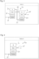
- FIG. 3 and 4 illustrate the handover of a transport element from a station ("Station 1" according to Fig. 3 ) to the station immediately following it in the direction of movement x (“Station 2”) Fig. 4).
- Fig. 3 essentially corresponds Fig. 2 , where the in Fig. 2 Instance I 1 shown, corresponding to the frontmost transport element in the direction of movement x, which is assigned to the station, has already been transferred to the next station and has therefore been removed from the list Lsi.
- the link 23 of the instance I 2 was changed accordingly to a null reference, so that it can be seen that "Carrier 10" is the frontmost transport element in the direction of movement x, which is currently assigned to "Station 1".
- the list L S2 of the station immediately following in the direction of movement x contains, as the only entry, the instance I 1 , which was previously assigned to station 1. This means that station 2 is exclusively assigned to carrier 1. Accordingly, both links 23, 25 are provided with a null reference.
- the transfer of the respective instances can be accomplished by overwriting the memory addresses to which the affected pointers point, so that the transferred instance is correctly selected from the list or chain of the previous station is removed and placed in the list or chain of the subsequent station.
- the transfer is event-controlled without the need for separate transfer points, which are also referred to as “trigger points”. All that is required is a defined handover condition. This can be, for example, that the transport element has started moving or a certain transfer speed has reached. For example, it is possible for the transport element to be transferred to the following station immediately after it has started moving, even if it has not yet arrived there. It is not necessary to stop at a waiting position or transfer position if the receiving station is free. If the currently executed transport order goes beyond the receiving station and the receiving station is free, it can even immediately pass the transport element on to the next station. The travel time can then be used to prepare commands for the transport element. Ideally, unnecessary stopping processes for the respective transport element can be avoided.
- the method described here leads on the one hand to a saving of memory, but on the other hand also to improved and simplified handling of transport elements on the route.
Landscapes
- Engineering & Computer Science (AREA)
- Physics & Mathematics (AREA)
- Automation & Control Theory (AREA)
- Quality & Reliability (AREA)
- Manufacturing & Machinery (AREA)
- General Physics & Mathematics (AREA)
- General Engineering & Computer Science (AREA)
- Chemical & Material Sciences (AREA)
- Combustion & Propulsion (AREA)
- Electromagnetism (AREA)
- Power Engineering (AREA)
- Mechanical Engineering (AREA)
- Non-Mechanical Conveyors (AREA)
Abstract
- Erzeugen einer Instanz für jedes der Transportelemente,
- Erzeugen einer Liste für jede der Stationen, wobei der Liste die Instanz für jedes der jeweiligen Station zugeordneten Transportelemente zugeordnet wird, und wobei innerhalb der jeweiligen Liste die Instanz eines jeden Transportelements mit der Instanz des Transportelements unmittelbar voraus und mit der Instanz des Transportelements unmittelbar hinter dem betrachteten Transportelement verknüpft wird,
- Übergeben eines Transportelements von einer ersten Station an eine unmittelbar nachfolgende zweite Station und Einfügen der Instanz dieses Transportelements in die Liste der zweiten Station, wenn für das Transportelement ein über die erste Station hinausgehender Fahrauftrag vorliegt,
wobei das Übergeben der Instanz ereignisgesteuert und unabhängig von einem Übergabepunkt erfolgt, wenn eine vorbestimmte Übergabebedingung erfüllt ist, und
- Ansteuern der Linearmotoren, um Fahraufträge der Transportelemente auszuführen.
Description
- Die Erfindung betrifft ein Verfahren zum Betreiben eines Transportsystems, insbesondere eines Multi-Carrier-Systems, welches mehrere Linearmotoren, die aneinandergereiht angeordnet sind und eine Führungsbahn aufweisen, mehrere Transportelemente, die mittels der Linearmotoren entlang der Führungsbahn bewegbar sind, und mehrere Stationen entlang der Führungsbahn umfasst, wobei jedes der Transportelemente einer der Stationen zugeordnet ist. Außerdem betrifft die Erfindung ein Transportsystem, insbesondere Multi-Carrier-System, mit einer Steuereinheit, die ausgebildet ist, das Verfahren auszuführen.
- Das Vorsehen von Stationen entlang der Führungsbahn oder Strecke eines Transportsystems ist grundsätzlich bekannt. Derartige Stationen sind mögliche Start- und Zielpunkte für Transportelemente. An den Stationen werden häufig bestimmte Aktionen ausgeführt. Beispielsweise können Transportelemente an den Stationen mit einem Produkt be- oder entladen werden.
- Üblicherweise ist jeder Station eine entlang der Strecke vorgelagerte Warteposition zugeordnet. Wenn ein Transportelement zu der nächsten Station geschickt werden soll, erhält es einen Fahrauftrag bis zu der entsprechenden Warteposition. Erst wenn es an der Warteposition eintrifft und dort anhält, übernimmt die empfangende Station und prüft, ob sie bereits von einem anderen Transportelement belegt ist. Erst wenn die Station frei ist, erhält das Transportelement die Freigabe, in die eigentliche Station vorzurücken. Dies bedeutet aber auch, dass das Transportelement selbst dann kurz in der Warteposition hält, wenn die Station bereits bei Eintreffen des Transportelements in der Warteposition frei ist. Zudem werden Transportelemente selbst dann in einer Station oder ihrer Warteposition angehalten, wenn sie einen Fahrauftrag zu einer nachgelagerten Station haben. Die (vorgelagerte) Station stellt dies fest und übergibt das Transportelement erst dann an die nächste (nachgelagerte) Station.
- Derartige Übergabepunkte sind bislang nötig, um eine geordnete Übergabe eines Transportelements von einer Station zur nächsten Station zu gewährleisten, sodass jede Station die ihr zugeordneten Transportelemente kennt. Dazu muss außerdem jede Station einen verfügbaren Speicher haben, der der maximalen Anzahl aller Transportelemente auf der Strecke entspricht, da jede Station eingerichtet sein muss, alle Transportelemente gleichzeitig zu verwalten. Bei Übergabe an eine Station wird das jeweilige Transportelement in dem Speicher vermerkt und aus dem Speicher der vorherigen Station entfernt. Das Speichern der Transportelemente bzw. ihrer Indexe erfolgt aber unstrukturiert, sodass zusätzliche Maßnahmen getroffen werden müssen, um die Reihenfolge der der Station zugeordneten Transportelemente entlang der Strecke nachvollziehen zu können, sodass die richtigen Transportelemente angesprochen werden. Dies ist aufwändig und erfordert zusätzlichen Speicher.
- Zudem ist das gegebenenfalls mehrfache und teils unnötige Anhalten der Transportelemente während des Fahrauftrags jedoch allein organisatorischen Gesichtspunkten geschuldet und wäre idealerweise zu vermeiden. Die dadurch bedingten Verzögerungen erhöhen sich, je mehr Stationen entlang der Strecke vorgesehen sind.
- Es ist eine Aufgabe der vorliegenden Erfindung, ein Verfahren zum Betreiben eines Transportsystems und ein Transportsystem mit einem verbesserten Handling von Transportelementen anzugeben.
- Diese Aufgabe wird durch den Gegenstand der unabhängigen Ansprüche gelöst. Vorteilhafte Ausgestaltungen sind Gegenstand der Unteransprüche und ergeben sich aus der Beschreibung und den Zeichnungen.
- Das erfindungsgemäße Verfahren dient zum Betreiben eines Transportsystems, insbesondere eines Multi-Carrier-Systems, wobei das Transportsystem mehrere Linearmotoren, die aneinandergereiht angeordnet sind und eine Führungsbahn aufweisen, mehrere Transportelemente, die mittels der Linearmotoren entlang der Führungsbahn bewegbar sind, und mehrere Stationen entlang der Führungsbahn umfasst, und wobei jedes der Transportelemente einer der Stationen zugeordnet ist. Das Verfahren weist die folgenden Schritte auf:
- Erzeugen einer Instanz für jedes der Transportelemente,
- Erzeugen einer Liste für jede der Stationen, wobei der Liste die Instanz für jedes der jeweiligen Station zugeordneten Transportelemente zugeordnet wird, und wobei innerhalb der jeweiligen Liste die Instanz eines jeden Transportelements mit der Instanz des Transportelements unmittelbar voraus und mit der Instanz des Transportelements unmittelbar hinter dem betrachteten Transportelement verknüpft wird,
- Übergeben eines Transportelements von einer ersten Station an eine unmittelbar nachfolgende zweite Station und Einfügen der Instanz dieses Transportelements in die Liste der zweiten Station, wenn für das Transportelement ein über die erste Station hinausgehender Fahrauftrag vorliegt,
wobei das Übergeben der Instanz ereignisgesteuert und unabhängig von einem Übergabepunkt erfolgt, wenn eine vorbestimmte Übergabebedingung erfüllt ist, und - Ansteuern der Linearmotoren, um Fahraufträge der Transportelemente auszuführen.
- Jeder Linearmotor kann insbesondere sechs Außenflächen aufweisen, nämlich Oberseite, Unterseite, Außenseite, Innenseite und zwei Seitenflächen. Dabei sind die Seitenflächen von benachbarten Linearmotoren durch einen geringen Dehnungsspalt von etwa 0,1 mm bis 0,2 mm zueinander beabstandet oder liegen direkt aneinander an. An der Außenseite kann die Führungsbahn für die Transportelemente ausgebildet sein. Die Innenseite ist im Bereich eines Innenraums des Transportsystems angeordnet.
- Das Transportsystem bzw. das Multi-Carrier-System kann umlaufend ausgebildet sein, sodass die Linearmotoren eine in sich geschlossene Führungsbahn bilden, entlang der das Transportelement oder die Transportelemente theoretisch endlos in derselben Richtung bewegt werden können. Allerdings ist es auch möglich, dass die Linearmotoren eine offene Führungsbahn mit einem Startpunkt und einem Endpunkt bilden. Entlang der Führungsbahn sind mehrere Stationen angeordnet, die aber in der Regel nur virtuell existieren und beispielsweise durch eine Koordinate der Führungsbahn definiert sind. Derartige Stationen sind mögliche Start- und Zielpunkte für Transportelemente. Beispielsweise kann ein Transportelement einen Fahrauftrag erhalten, der ihn von einer Station zu einer anderen Station fahren lässt, was einem Teilabschnitt der Führungsbahn entspricht. An den Stationen können außerdem Aktionen ausgeführt werden, wie zum Beispiel das Be- oder Entladen des Transportelements mit einem Produkt oder das Koppeln oder Entkoppeln einer bestimmten Anzahl von aufeinanderfolgenden Transportelementen.
- Die Transportelemente werden insbesondere magnetisch angetrieben. Dazu weisen die Transportelemente einen oder mehrere Permanentmagnete auf, welche mittels eines sich verändernden und/oder wandernden Magnetfelds, welches von den Linearmotoren erzeugt wird, mit einer Antriebskraft beaufschlagt werden. Die Antriebskraft führt zu einer Bewegung der Transportelemente entlang der Führungsbahn. Insbesondere können die Transportelemente unabhängig und separat voneinander bewegt werden. Mittels der Transportelemente können dadurch beispielsweise Werkstücke oder Produkte entlang der Führungsbahn transportiert werden.
- Um die Transportelemente auf der Führungsbahn zu halten, werden diese bevorzugt mittels einer Anziehungskraft in einer zu einer Bewegungsrichtung des Transportelements senkrechten Richtung zu der Führungsbahn hingezogen. Somit verläuft die Anziehungskraft auch senkrecht zu der Antriebskraft. Die Anziehungskraft verläuft bevorzugt von der Führungsbahn hin zu den Linearmotoren bzw. zu den Spulen des Linearmotors. Die Anziehungskraft wird üblicherweise dadurch erzeugt, dass der Magnet des Transportelements von einem magnetisch leitfähigen Stator des jeweiligen Linearmotors angezogen wird.
- Das Transportelement kann auch als Carrier, Mover oder Läufer, der Linearmotor hingegen auch als Stator bezeichnet werden.
- Das Erzeugen einer Instanz für jedes der Transportelemente bedeutet, dass jedes auf der Strecke oder Führungsbahn befindliche Transportelement ein virtuelles Abbild zugeordnet erhält, wobei die Instanzen vorzugsweise identisch aufgebaut sind. Es wird gleichsam ein Instanzenpool angelegt, sodass für jedes Transportelement genau eine Instanz vorhanden ist. Jedes der Transportelemente, und damit auch jede Instanz, ist genau einer der Stationen zugeordnet, wobei das Transportelement bzw. die Instanz auch übergeben werden kann, beispielsweise von einer Station an die entlang der Führungsbahn nachfolgende Station.
- Jede Station erhält außerdem die Liste mit den der Station aktuell zugewiesenen Instanzen zugeordnet. Dadurch, dass innerhalb der jeweiligen Liste die Instanz eines jeden Transportelements mit der Instanz des Transportelements unmittelbar voraus und mit der Instanz des Transportelements unmittelbar hinter dem betrachteten Transportelement verknüpft ist, kennt die Station die Reihenfolge der ihr zugewiesenen Transportelemente. Eine zusätzliche Verwaltung der Reihenfolge der der Station zugeordneten Transportelemente entlang der Strecke ist dadurch hinfällig, da die Station aufgrund der Liste oder Kette immer das erste Listenelement kennt, welches dem in Bewegungsrichtung vordersten Transportelement entspricht. Insbesondere erteilt die Station immer dem ersten Element der Liste oder Kette, welches mit diesem vordersten Transportelement verknüpft ist, insbesondere auf dessen Index verweist, den nächsten Fahrauftrag.
- Bei der Instanz des in Fahrtrichtung vordersten Transportelements, das der Station zugewiesen ist, also der ersten Instanz in der Liste, ist die Verknüpfung zur vorderen Instanz vorzugsweise als Verknüpfung ins Leere gekennzeichnet, beispielsweise als NULL-Verweis. Entsprechend verhält es sich bei der Instanz des in Fahrtrichtung letzten Transportelements, das der Station zugewiesen ist, also der letzten Instanz in der Liste. Bei dieser ist vorzugsweise die Verknüpfung zur hinteren Instanz als Verknüpfung ins Leere gekennzeichnet. So ist für die Station jeweils ermittelbar, welche Transportelemente ihr zugewiesen sind, in welcher Reihenfolge diese angeordnet sind und welches das erste und welches das letzte Transportelement in Bewegungsrichtung ist, welches der Station zugeordnet ist. Dadurch, dass für jedes Transportelement global gesehen genau eine Instanz angelegt ist und nicht jede Station ausreichenden Speicher für die maximale Anzahl an Transportelementen auf der Strecke vorhalten muss, kann zudem eine nennenswerte Speicherersparnis erreicht werden.
- Soweit von Transportelementen "voraus", "davor", "vor" oder "hinter" dem betrachteten Transportelement gesprochen wird, bezieht sich dies auf die Bewegungsrichtung. Das Transportelement "voraus" oder "davor" bezeichnet also ein in der Bewegungsrichtung vorausfahrendes Transportelement, während das Transportelement "hinter" dem betrachteten Transportelement ein dem betrachteten Transportelement in gleicher Richtung folgendes Transportelement bezeichnet. Eine "nachfolgende" (zweite) Station bezeichnet dementsprechend eine in der Bewegungsrichtung der betrachteten (ersten) Station nachgelagerte Station.
- Sofern der Begriff "unmittelbar" im Zusammenhang mit Transportelementen oder Stationen verwendet wird, beinhaltet dieser keine Aussage über zeitliche oder räumliche Abstände, sondern bedeutet, dass zwischen den entsprechenden Stationen oder Transportelementen keine weiteren Stationen bzw. Transportelemente befindlich sind.
- Wenn ein Transportelement von einer Station an eine unmittelbar nachfolgende Station übergeben wird, wird die entsprechende Instanz dieses Transportelements in die Liste der zweiten Station eingefügt, das heißt an die letzte Position der Liste angehängt. Entsprechend wird die Instanz aus der Liste der vorhergehenden Station bei der Übergabe entfernt. Mit der Übergabe wechselt vorzugsweise die Zuständigkeit der Stationen für das Transportelement, sodass diese Befehle für das Transportelement ausführen können.
- Die Übergabe erfolgt ereignisgesteuert und unabhängig von einem Übergabepunkt (d.h. einem, insbesondere vorbestimmten, Punkt oder Abschnitt auf der Führungsbahn, der von einem Transportelement angefahren oder besetzt werden kann), auch als Triggerpoint bezeichnet. Das heißt es bedarf keines definierten Übergabepunkts, entsprechend beispielsweise einer Warteposition, zu welcher das Transportelement erst bewegt werden muss. Vielmehr kann das Transportelement ereignisbasiert übergeben, wobei das jeweilige Übergabeereignis nahezu frei definierbar ist. Dies ermöglicht es, dass die Station, an die das Transportelement übergeben wird, gegebenenfalls schon vor Ankunft des Transportelements überprüfen kann, ob das Transportelement vor der Station halten muss, da diese belegt ist, oder unmittelbar in die Station einfahren kann. Wenn das Transportelement einen Fahrauftrag zu einer noch weiter nachgelagerten Station ausführt, kann dieses außerdem sofort an die nächste Station weitergegeben werden, noch bevor das Transportelement eintrifft. Somit bleibt ein unnötiges Anhalten in einer Warteposition und auch ein unnötiges Warten in einer Station, die nicht Ziel des Transportelements ist, aus.
- In bevorzugter Ausgestaltung ist die Übergabebedingung erfüllt, wenn das Transportelement losgefahren ist und/oder eine vorbestimmte Übergabegeschwindigkeit erreicht hat. Insbesondere kann das Transportelement unmittelbar an die nächste Station übergeben werden, nachdem dieses losgefahren ist. Es muss also nicht erst abgewartet werden, bis das Transportelement in einer Warteposition ankommt. Vielmehr kann die Fahrstrecke zwischen zwei Stationen bereits genutzt werden, damit die Ankunftsstation prüft, ob die Station derzeit frei oder belegt ist und ob sie das Transportelement noch weiter an die ihr nachfolgende Station übergeben muss.
- Vorzugsweise weist jede Instanz die Verknüpfung mit der Instanz des Transportelements unmittelbar davor, die Verknüpfung mit der Instanz des Transportelements unmittelbar hinter dem betrachteten Transportelement und ein Identifikationsmerkmal für das jeweilige Transportelement auf. So kann für jedes Transportelement zuverlässig ermittelt werden, ob es noch voraus- oder nachfahrende Transportelemente gibt, die derselben Station zugeordnet sind, und um welches Transportelement es sich handelt.
- Insbesondere können die Verknüpfungen jeweils als auf Speicheradressen der jeweiligen Instanz verweisende Pointer oder Zeiger ausgebildet sein. Das Übergeben einer Instanz von der ersten Station an die unmittelbar nachfolgende zweite Station kann dann dadurch erfolgen, dass die Speicheradressen, auf welche die jeweiligen Pointer verweisen, überschrieben (und dabei entsprechend abgeändert) werden. Dies stellt einen besonderen effizienten und schnellen Weg dar, das "Übergeben" der Instanz von einer Liste an eine andere Liste darzustellen.
- Genauer gesagt, können die Instanzen, die den bei einer Station befindlichen Transportelementen zugeordnet sind, jeweils eine verkettete Liste bilden. Jede Instanz kann dabei einen Pointer oder Zeiger auf die vorherige und die nachfolgende Instanz aufweisen. Die Instanzen des - auf der Führungsbahn - ersten und letzten Transportelements können dabei einen Null-Pointer (oder Null-Zeiger) aufweisen. Bewegt sich nun das erste Transportelement von einer ersten Station zu einer zweiten Station, so werden die Pointer oder Zeiger derart abgeändert, dass die Instanz des Transportelements in die verkettete Liste der Instanzen der zweiten Station integriert wird.
- Das Transportsystem kann außerdem eine Steuereinheit aufweisen, wobei in der Steuereinheit ein Speicherbereich zur Anlage von Instanzen für jedes der Transportelemente vorgehalten wird. So wird ein globaler "Pool" von Instanzen gebildet, bei dem die Instanzen über Referenzieren (z.B. durch die vorgenannten Pointer oder Zeiger) in den Listen oder Ketten verknüpft werden können, ohne dass jede Station einen Speicher für die maximale, theoretisch mögliche Anzahl an Transportelementen vorhalten muss.
- Die Erfindung betrifft außerdem ein Transportsystem, insbesondere ein Multi-Carrier-System, welches mehrere Linearmotoren, die aneinandergereiht angeordnet sind und eine Führungsbahn aufweisen, mehrere Transportelemente, die mittels der Linearmotoren entlang der Führungsbahn bewegbar sind, und mehrere Stationen entlang der Führungsbahn umfasst. Außerdem weist das Transportsystem eine Steuereinheit auf, die ausgebildet ist, das erfindungsgemäße Verfahren auszuführen.
- Bei dem Transportsystem können die Stationen zumindest teilweise an identischen Positionen entlang der Führungsbahn angeordnet sein. Dadurch, dass es keiner hardwaremäßigen Übergabepunkte oder Triggerpoints bedarf, können Stationen rein virtuell durch Ihre Position oder Koordinate entlang der Führungsbahn definiert werden. Dies schließt auch ein, dass unterschiedliche Stationen an derselben Position oder Koordinate definiert werden können, die dann beispielsweise unterschiedliche Funktionen erfüllen können.
- Im Übrigen gelten zu dem erfindungsgemäßen Transportsystem die zum erfindungsgemäßen Verfahren getroffenen Aussagen entsprechend und umgekehrt. Es versteht sich, dass sämtliche hierin genannten Merkmale und Ausführungsformen miteinander kombinierbar sind, sofern nicht etwas gegenteiliges angegeben ist.
- Nachfolgend wird die Erfindung schematisch und beispielhaft unter Bezugnahme auf die Zeichnungen beschrieben. Darin zeigt:
- Fig. 1
- eine Draufsicht auf ein als Multi-Carrier-System ausgebildetes Transportsystem gemäß einem Ausführungsbeispiel,
- Fig. 2
- ein Beispiel für eine Liste einer Station, der drei Transportelemente zugeordnet sind,
- Fig. 3
- die Liste aus
Fig. 2 , nachdem die erste Instanz in der Liste einer nachfolgenden Station übergeben worden ist, und - Fig. 4
- die Liste der nachfolgenden Station, nachdem die erste Instanz der Liste aus
Fig. 2 an diese übergeben worden ist. -
Fig. 1 zeigt schematisch ein als Multi-Carrier-System ausgebildetes Transportsystem 10 in Draufsicht, das eine Vielzahl von Linearmotoren 11 aufweist, welche im vorliegenden Ausführungsbeispiel in sich geschlossen aneinandergereiht angeordnet sind und eine geschlossene Führungsbahn 13 für Transportelemente 15, 17, 19 ausbilden. Zur anschaulichen Beschreibung sind inFig. 1 nur drei Transportelemente 15, 17, 19 dargestellt, nämlich ein erstes Transportelement 15, ein zweites Transportelement 17, das sich in Bewegungsrichtung x unmittelbar vor dem ersten Transportelement 15 befindet, und ein drittes Transportelement 19, das sich in Bewegungsrichtung x unmittelbar hinter dem ersten Transportelement 15 befindet. "Unmittelbar" ist dabei nicht so zu verstehen, dass sich dies auf einen bestimmten Abstand zwischen den jeweiligen Transportelementen 15, 17, 19 bezieht, sondern bedeutet vielmehr, dass sich zwischen unmittelbar aufeinander folgenden Transportelementen 15, 17, 19 kein weiteres Transportelement befindet. - Die Transportelemente 15, 17, 19 werden durch die Linearmotoren 11 magnetisch angetrieben. Dazu weisen die Transportelemente 15, 17, 19 einen oder mehrere nicht dargestellte Permanentmagnete auf, welche mittels eines sich verändernden und/oder wandernden Magnetfelds, welches von den Linearmotoren 11 erzeugt wird, mit einer Antriebskraft beaufschlagt werden. Die Antriebskraft führt zu einer Bewegung der Transportelemente 15, 17, 19 entlang der Führungsbahn 13. Insbesondere können die Transportelemente 15, 17, 19 unabhängig und separat voneinander bewegt werden. Die Linearmotoren 11 werden von einer nicht dargestellten Steuereinheit angesteuert, um die jeweiligen Transportelemente 15, 17, 19 anzutreiben.
- Wie
Fig. 1 zu entnehmen ist, sind entlang der Führungsbahn 13 mehrere Stationen S1, S2, S3 angeordnet, die beispielsweise durch ihre Position in der Bewegungsrichtung x entlang der Führungsbahn 13 definiert sein können. An den Stationen können beispielsweise Transportelemente 15, 17, 19 zusammengefasst oder wieder vereinzelt werden oder ein Produkt zum Transport aufnehmen oder wieder abliefern. Beispielsweise können die Transportelemente 15, 17, 19 von der Steuereinheit eine Anweisung erhalten, die das jeweilige Transportelement von Station S1 zu Station S2 fahren lässt. Derartige Anweisungen werden auch als Fahrauftrag bezeichnet. InFig. 1 ist jede der Stationen S1, S2, S3 an einer eigenen Position oder Koordinate entlang der Führungsbahn 13 angeordnet. Grundsätzlich ist alternativ auch umsetzbar, dass die im vorliegenden Ausführungsbeispiel rein virtuell durch Ihre Position oder Koordinate entlang der Führungsbahn 13 definierten Stationen S1, S2, S3 vollständig oder teilweise an identischen Positionen oder Koordinaten angeordnet sind, die dann beispielsweise unterschiedliche Funktionen wahrnehmen können. - Jedes der Transportelemente 15, 17, 19 auf der Strecke ist zu jedem Zeitpunkt genau einer der Stationen S1, S2, S3 zugeordnet. Dies bedeutet, dass die jeweilige Station S1, S2, S3 für die ihr zugeordneten Transportelemente 15, 17, 19 zuständig ist und mittels der Steuereinheit Befehle für die Transportelemente 15, 17, 19 ausführen kann, insbesondere zum Anhalten oder Fahren.
-
Fig. 2 zeigt ein Beispiel von einer erfindungsgemäßen Zuordnung von drei Transportelementen zu einer Station, wobeiFig. 2 als rein schematische Wiedergabe einer beispielhaft verwendeten Datenstruktur zu verstehen ist. - Erfindungsgemäß wird für jedes Transportelement (auch als Carrier, Mover oder Läufer bezeichnet), das sich auf der Strecke befindet, eine Instanz angelegt. Wenn beispielsweise zwanzig Transportelemente auf der Strecke bewegt werden, so werden zwanzig Instanzen angelegt, sodass ein entsprechender Pool mit einer Instanz für jedes Transportelement vorhanden ist. Dies geschieht insbesondere in einem zentralen Speicherbereich der Steuereinheit, der für die maximale Anzahl Transportelementen zentral vorgehalten wird.
Fig. 2 zeigt beispielhaft eine Liste Lsi einer Station (als "Station 1" bezeichnet). Die Liste Lsi kann auch als Kette bezeichnet werden und enthält drei Instanzen I1, I2, I3, welche jeweils einem Transportelement zugeordnet sind. - Jede der Instanzen I1, I2, I3 ist mit einem Identifikationsmerkmal 21 versehen, welches das der jeweiligen Instanz I1, I2, I3 entsprechende Transportelement eindeutig identifiziert ("Carrier 1", "Carrier 10", "Carrier 9"). Zudem weist jede Instanz I1, I2, I3 eine Verknüpfung 23 mit der Instanz des Transportelements unmittelbar voraus und eine Verknüpfung 25 mit der Instanz des Transportelements unmittelbar hinter dem betrachteten Transportelement auf. Die Verknüpfungen 23, 25 sind insbesondere als Pointer ausgebildet, welche auf die Speicherbereiche der jeweiligen Zielelemente verweisen. Sofern es sich um das in Bewegungsrichtung x vorderste Transportelement oder um das in Bewegungsrichtung x letzte Transportelement handelt, welches der entsprechenden Station zugeordnet ist, sind die jeweiligen Verknüpfungen 23, 25 als Verknüpfung ins Leere gekennzeichnet, nämlich hier als Null-Verweis, siehe Verknüpfung 23 der Instanz I1 und Verknüpfung 25 der Instanz I3.
- Mit dieser Datenstruktur ergibt sich für die Station zu jedem Zeitpunkt aufgrund ihrer Liste ein Überblick über alle ihr zugeordneten Transportelemente, deren logische Reihenfolge entlang der Bewegungsrichtung x und aufgrund der Null-Verweise auch darüber, welches Transportelement das erste bzw. das letzte Transportelement entlang der Bewegungsrichtung x ist, das der Station zugeordnet ist. Dabei können erhebliche Speichereinsparungen erzielt werden, da nicht für jede Station ausreichend Speicher für die maximale Anzahl an Transportelementen vorgehalten werden muss. Vielmehr wird ein globaler Pool von Instanzen angelegt, die jeweils einer Liste oder Kette zugeordnet sind. Zudem ist eine zusätzliche Verwaltung der Reihenfolge der der Station zugeordneten Transportelemente entlang der Strecke obsolet. Die Station, die immer dem ersten Element der Liste oder Kette, welches mit diesem vordersten Transportelement verknüpft ist, den nächsten Fahrauftrag erteilen wird, kann das entsprechende Transportelement immer über den ersten Eintrag ihrer Liste ansprechen.
-
Fig. 3 und 4 veranschaulichen die Übergabe eines Transportelements von einer Station ("Station 1" gemäßFig. 3 ) an die ihr unmittelbar in Bewegungsrichtung x nachfolgende Station ("Station 2" gemäßFig. 4). Fig. 3 entspricht im WesentlichenFig. 2 , wobei die inFig. 2 gezeigte Instanz I1, entsprechend dem in Bewegungsrichtung x vordersten Transportelement, welches der Station zugewiesen ist, bereits an die nächste Station übergeben worden ist und daher aus der Liste Lsi entfernt worden ist. Die Verknüpfung 23 der Instanz I2 wurde entsprechend in einen Null-Verweis geändert, sodass ersichtlich ist, dass "Carrier 10" das in Bewegungsrichtung x vorderste Transportelement ist, welches der "Station 1" derzeit zugeordnet ist. - Gemäß
Fig. 4 enthält die Liste LS2 der unmittelbar in Bewegungsrichtung x nachfolgenden Station ("Station 2") nach der Übergabe als einzigen Eintrag die Instanz I1, welche zuvor Station 1 zugeordnet war. Das heißt, Station 2 ist ausschließlich der Carrier 1 zugewiesen. Entsprechend sind beide Verknüpfungen 23, 25 mit einem Null-Verweis versehen. - Das Übergeben der jeweiligen Instanzen kann bei einer Umsetzungen mit Pointern als Verknüpfungen 23, 25 also schon dadurch bewerkstelligt werden, dass die Speicheradressen, auf welche die betroffenen Pointer jeweils verweisen, überschrieben werden, sodass die übergebene Instanz korrekt aus der Liste oder Verkettung der vorangehenden Station entfernt wird und in die Liste oder Verkettung der nachfolgenden Station eingereiht wird.
- Die Übergabe erfolgt ereignisgesteuert ohne dass es separater Übergabepunkte bedarf, die auch als "Triggerpoint" bezeichnet werden. Erforderlich ist lediglich eine definierte Übergabebedingung. Dies kann beispielsweise sein, dass sich das Transportelement in Bewegung gesetzt hat oder eine bestimmte Übergabegeschwindigkeit erreicht hat. So ist es beispielsweise möglich, dass das Transportelement sofort nach der Bewegungsaufnahme an die nachfolgende Station übergeben wird, auch wenn es noch gar nicht dort angekommen ist. Ein Anhalten an einer Warteposition oder Übergabeposition ist dann nicht nötig, wenn die empfangende Station frei ist. Sollte der derzeit ausgeführte Fahrauftrag über die empfangende Station hinaus gehen und die empfangende Station frei sein, so kann diese das Transportelement sogar unmittelbar weiter an die nächste nachfolgende Station übergeben. Die Fahrzeit kann so bereits dazu genutzt werden, Befehle für das Transportelement vorzubereiten. Idealerweise können unnötige Anhaltevorgänge für das jeweilige Transportelement vermieden werden.
- Das hier beschriebene Verfahren führt damit zum einen zu einer Einsparung von Speicher, zum anderen aber auch zu einem verbesserten und vereinfachten Handling von Transportelementen auf der Strecke.
-
- 10
- Transportsystem
- 11
- Linearmotor
- 13
- Führungsbahn
- 15
- erstes Transportelement
- 17
- zweites Transportelement
- 19
- drittes Transportelement
- 21
- Identifikationsmerkmal
- 23
- Verknüpfung
- 25
- Verknüpfung
- I1
- Instanz
- I2
- Instanz
- I3
- Instanz
- Lsi
- Liste (Station 1)
- LS2
- Liste (Station 2)
- S1
- Station
- S2
- Station
- S3
- Station
- x
- Bewegungsrichtung
Claims (9)
- Verfahren zum Betreiben eines Transportsystems (10), insbesondere eines Multi-Carrier-Systems, welchesmehrere Linearmotoren (11), die aneinandergereiht angeordnet sind und eine Führungsbahn (13) aufweisen,mehrere Transportelemente (15, 17, 19), die mittels der Linearmotoren (11) entlang der Führungsbahn (13) bewegbar sind, undmehrere Stationen (S1, S2, S3) entlang der Führungsbahn (13) umfasst, wobei jedes der Transportelemente (15, 17, 19) einer der Stationen (S1, S2, S3) zugeordnet ist, und wobei das Verfahren die folgenden Schritte aufweist:- Erzeugen einer Instanz (I1, I2, I3) für jedes der Transportelemente (15, 17, 19),- Erzeugen einer Liste (LS1, LS2) für jede der Stationen (S1, S2, S3), wobei der Liste (LS1, LS2) die Instanz (I1, I2, I3) für jedes der jeweiligen Station zugeordneten Transportelemente (15, 17, 19) zugeordnet wird, und wobei innerhalb der jeweiligen Liste (LS1, LS2) die Instanz (I1, I2, I3) eines jeden Transportelements (15, 17, 19) mit der Instanz (I1, I2, I3) des Transportelements (15, 17, 19) unmittelbar voraus und mit der Instanz (I1, I2, I3) des Transportelements (15, 17, 19) unmittelbar hinter dem betrachteten Transportelement (15, 17, 19) verknüpft wird,- Übergeben eines Transportelements (15, 17, 19) von einer ersten Station an eine unmittelbar nachfolgende zweite Station und Einfügen der Instanz (I1, I2, I3) dieses Transportelements (15, 17, 19) in die Liste (LS2) der zweiten Station, wenn für das Transportelement (15, 17, 19) ein über die erste Station hinausgehender Fahrauftrag vorliegt,wobei das Übergeben ereignisgesteuert und unabhängig von einem Übergabepunkt erfolgt, wenn eine vorbestimmte Übergabebedingung erfüllt ist, und- Ansteuern der Linearmotoren (11), um Fahraufträge der Transportelemente (15, 17, 19) auszuführen.
- Verfahren nach Anspruch 1,
dadurch gekennzeichnet, dass die Übergabebedingung erfüllt ist, wenn das Transportelement (15, 17, 19) losgefahren ist und/oder eine vorbestimmte Übergabegeschwindigkeit erreicht hat. - Verfahren nach Anspruch 1 oder 2,
dadurch gekennzeichnet, dass jede Instanz (I1, I2, I3) die Verknüpfung (23) mit der Instanz (I1, I2, I3) des Transportelements (15, 17, 19) unmittelbar davor, die Verknüpfung (25) mit der Instanz (I1, I2, I3) des Transportelements (15, 17, 19) unmittelbar hinter dem betrachteten Transportelement (15, 17, 19) und ein Identifikationsmerkmal (21) für das jeweilige Transportelement (15, 17, 19) aufweist. - Verfahren nach Anspruch 3,
dadurch gekennzeichnet, dass die Verknüpfungen (23, 25) jeweils als auf Speicheradressen der jeweiligen Instanz (I1, I2, I3) verweisende Pointer ausgebildet sind. - Verfahren nach Anspruch 4,
dadurch gekennzeichnet, dass das Übergeben einer Instanz (I1, I2, I3) von der ersten Station an die unmittelbar nachfolgende zweite Station dadurch erfolgt, dass die Speicheradressen, auf welche die jeweiligen Pointer verweisen, überschrieben werden. - Verfahren nach einem der vorstehenden Ansprüche,
dadurch gekennzeichnet, dass das Transportsystem (10) eine Steuereinheit aufweist und in der Steuereinheit ein Speicherbereich zur Anlage von Instanzen (I1, I2, I3) für jedes der Transportelemente (15, 17, 19) vorgehalten wird. - Verfahren nach einem der vorstehenden Ansprüche,
dadurch gekennzeichnet, dass die Stationen (S1, S2, S3) zumindest teilweise an identischen Positionen entlang der Führungsbahn (13) angeordnet sind. - Transportsystem (10), insbesondere Multi-Carrier-System, welches mehrere Linearmotoren (11), die aneinandergereiht angeordnet sind und eine Führungsbahn (13) aufweisen, mehrere Transportelemente (15, 17, 19), die mittels der Linearmotoren (11) entlang der Führungsbahn (13) bewegbar sind, und mehrere Stationen (S1, S2, S3) entlang der Führungsbahn (13) umfasst
gekennzeichnet durch eine Steuereinheit, die ausgebildet ist, das Verfahren nach einem der vorstehenden Ansprüche auszuführen. - Transportsystem (10) nach Anspruch 8,
dadurch gekennzeichnet, dass die Stationen (S1, S2, S3) zumindest teilweise an identischen Positionen entlang der Führungsbahn (13) angeordnet sind.
Priority Applications (3)
| Application Number | Priority Date | Filing Date | Title |
|---|---|---|---|
| EP22305911.4A EP4296811B1 (de) | 2022-06-23 | 2022-06-23 | Verfahren zum betreiben eines transportsystems sowie transportsystem |
| US18/211,659 US20240085893A1 (en) | 2022-06-23 | 2023-06-20 | Method for operating a transport system and transport system |
| CN202310749423.2A CN117284711A (zh) | 2022-06-23 | 2023-06-25 | 用于运行运输系统的方法和运输系统 |
Applications Claiming Priority (1)
| Application Number | Priority Date | Filing Date | Title |
|---|---|---|---|
| EP22305911.4A EP4296811B1 (de) | 2022-06-23 | 2022-06-23 | Verfahren zum betreiben eines transportsystems sowie transportsystem |
Publications (2)
| Publication Number | Publication Date |
|---|---|
| EP4296811A1 true EP4296811A1 (de) | 2023-12-27 |
| EP4296811B1 EP4296811B1 (de) | 2025-04-23 |
Family
ID=82748323
Family Applications (1)
| Application Number | Title | Priority Date | Filing Date |
|---|---|---|---|
| EP22305911.4A Active EP4296811B1 (de) | 2022-06-23 | 2022-06-23 | Verfahren zum betreiben eines transportsystems sowie transportsystem |
Country Status (3)
| Country | Link |
|---|---|
| US (1) | US20240085893A1 (de) |
| EP (1) | EP4296811B1 (de) |
| CN (1) | CN117284711A (de) |
Cited By (1)
| Publication number | Priority date | Publication date | Assignee | Title |
|---|---|---|---|---|
| WO2025238170A1 (de) * | 2024-05-15 | 2025-11-20 | Beckhoff Automation Gmbh | Verfahren zum betreiben eines linearen transportsystems und lineares transportsystem |
Families Citing this family (1)
| Publication number | Priority date | Publication date | Assignee | Title |
|---|---|---|---|---|
| JP7673102B2 (ja) * | 2023-01-12 | 2025-05-08 | 日本金銭機械株式会社 | 搬送システム |
Citations (4)
| Publication number | Priority date | Publication date | Assignee | Title |
|---|---|---|---|---|
| EP3196719A2 (de) * | 2016-01-25 | 2017-07-26 | Rockwell Automation Technologies, Inc. | Multi-mover-linearmotorsteuergerät zur bereitstellung eines gemeinsam genutzten koordinationssubsystems |
| WO2017186619A1 (de) * | 2016-04-29 | 2017-11-02 | Weber Maschinenbau Gmbh Breidenbach | Verfahren zum bewegen von portionen |
| US20200017308A1 (en) * | 2018-07-13 | 2020-01-16 | Rockwell Automation Technologies, Inc. | System and Method for Limiting Motion in an Independent Cart System |
| EP3974927A1 (de) * | 2020-09-25 | 2022-03-30 | Rockwell Automation Technologies, Inc. | Automatisierungssteuerung basierend auf einer referenzanordnung |
Family Cites Families (6)
| Publication number | Priority date | Publication date | Assignee | Title |
|---|---|---|---|---|
| FR3031510B1 (fr) * | 2015-01-13 | 2019-04-19 | Savoye | Systeme et procede de sequencement pour au moins un poste de preparation |
| EP3394690B1 (de) * | 2015-12-21 | 2020-04-01 | TGW Logistics Group GmbH | Verfahren zum sortieren von förderobjekten auf einer förderanlage |
| WO2018058020A1 (en) * | 2016-09-26 | 2018-03-29 | Intelligrated Headquarters, Llc | Fully validated material handling with shuttle container delivery system |
| US10977612B2 (en) * | 2019-04-02 | 2021-04-13 | Coupang, Corp. | Electronic inventory tracking system and associated user interfaces |
| US11829158B2 (en) * | 2021-08-25 | 2023-11-28 | Rockwell Automation Technologies, Inc. | System and method for synchronizing motion of multiple vehicles in an independent cart system |
| EP4440959A1 (de) * | 2021-11-29 | 2024-10-09 | Ferag Ag | Vorrichtung zum beladungsmanagement von transporteinheiten eines fördersystems |
-
2022
- 2022-06-23 EP EP22305911.4A patent/EP4296811B1/de active Active
-
2023
- 2023-06-20 US US18/211,659 patent/US20240085893A1/en active Pending
- 2023-06-25 CN CN202310749423.2A patent/CN117284711A/zh active Pending
Patent Citations (4)
| Publication number | Priority date | Publication date | Assignee | Title |
|---|---|---|---|---|
| EP3196719A2 (de) * | 2016-01-25 | 2017-07-26 | Rockwell Automation Technologies, Inc. | Multi-mover-linearmotorsteuergerät zur bereitstellung eines gemeinsam genutzten koordinationssubsystems |
| WO2017186619A1 (de) * | 2016-04-29 | 2017-11-02 | Weber Maschinenbau Gmbh Breidenbach | Verfahren zum bewegen von portionen |
| US20200017308A1 (en) * | 2018-07-13 | 2020-01-16 | Rockwell Automation Technologies, Inc. | System and Method for Limiting Motion in an Independent Cart System |
| EP3974927A1 (de) * | 2020-09-25 | 2022-03-30 | Rockwell Automation Technologies, Inc. | Automatisierungssteuerung basierend auf einer referenzanordnung |
Cited By (1)
| Publication number | Priority date | Publication date | Assignee | Title |
|---|---|---|---|---|
| WO2025238170A1 (de) * | 2024-05-15 | 2025-11-20 | Beckhoff Automation Gmbh | Verfahren zum betreiben eines linearen transportsystems und lineares transportsystem |
Also Published As
| Publication number | Publication date |
|---|---|
| CN117284711A (zh) | 2023-12-26 |
| US20240085893A1 (en) | 2024-03-14 |
| EP4296811B1 (de) | 2025-04-23 |
Similar Documents
| Publication | Publication Date | Title |
|---|---|---|
| DE102007014876B4 (de) | Transportsystem | |
| EP3385803B1 (de) | Verfahren zum betreiben eines langstatorlinearmotors | |
| EP4296811B1 (de) | Verfahren zum betreiben eines transportsystems sowie transportsystem | |
| AT520119A1 (de) | Bearbeitungsstation und Verfahren zum Bearbeiten eines Gegenstandes | |
| EP2106376A1 (de) | Intelligente stauförderbahn | |
| EP3599126B1 (de) | Verfahren zum betreiben eines langstatorlinearmotors mit weiche | |
| DE102017214816B4 (de) | Werkstück-Aufnahmesystem | |
| EP3510456B1 (de) | Verfahren zum montieren eines objekts | |
| EP0918646B1 (de) | Bearbeitungsverfahren zur bearbeitung von stückgut sowie steuerverfahren und einrichtung zur durchführung des bearbeitungsverfahrens | |
| WO1998025845A1 (de) | Verfahren und anordnung zum fördern von individuell gehaltenen produkten | |
| EP0950626B1 (de) | Vorrichtung zum Wechseln von Wickelständern an Wickelstationen | |
| EP4275942A1 (de) | Verfahren zum betreiben eines transportsystems sowie transportsystem | |
| DE2719229A1 (de) | Beschickungsvorrichtung fuer werkzeugmaschinen | |
| EP4490085B1 (de) | Steuerungskonzept für linearelektroantrieb-förderer | |
| DE102020213540B4 (de) | Fertigungsanlage zur Serienfertigung von Kraftfahrzeugen und Verfahren zum Fertigen eines Kraftfahrzeugs | |
| DE102022211887A1 (de) | Logistikeinrichtung und Verfahren zum flexiblen Fördern und Speichern von Gütern und entsprechendes Fertigungssystem | |
| WO1999033733A1 (de) | Verfahren sowie eine vorrichtung zur speicherung von transportelementen | |
| DE10158763A1 (de) | Gepäcktransportsystem über lange Distanzen | |
| DE102021118923A1 (de) | Förderguttransfer von trägheitsbasiert abgebendem Fahrzeug auf Stetigförderer | |
| WO2021090289A1 (de) | Kabelbearbeitungsmaschine | |
| DE112020006658T5 (de) | Träger, Verfahren zur Steuerung des Trägers, Programm, Teile-Bestückungssystem und Arbeitssystem | |
| EP0721807A2 (de) | Steuerung für fördertechnische Anlagen | |
| DE102023206047A1 (de) | Verfahren und Hybridsystem zum Konfigurieren einer Montagelinie für Bauteile insbesondere Karosseriebauteile | |
| DE102019128617B3 (de) | Verfahren zum Betreiben eines fahrerlosen Transportsystems und fahrerloses Transportsystem | |
| AT526757B1 (de) | Verfahren zur Verkehrsregelung in einem Transportsystem und Transportsystem |
Legal Events
| Date | Code | Title | Description |
|---|---|---|---|
| PUAI | Public reference made under article 153(3) epc to a published international application that has entered the european phase |
Free format text: ORIGINAL CODE: 0009012 |
|
| STAA | Information on the status of an ep patent application or granted ep patent |
Free format text: STATUS: REQUEST FOR EXAMINATION WAS MADE |
|
| 17P | Request for examination filed |
Effective date: 20230726 |
|
| AK | Designated contracting states |
Kind code of ref document: A1 Designated state(s): AL AT BE BG CH CY CZ DE DK EE ES FI FR GB GR HR HU IE IS IT LI LT LU LV MC MK MT NL NO PL PT RO RS SE SI SK SM TR |
|
| GRAP | Despatch of communication of intention to grant a patent |
Free format text: ORIGINAL CODE: EPIDOSNIGR1 |
|
| STAA | Information on the status of an ep patent application or granted ep patent |
Free format text: STATUS: GRANT OF PATENT IS INTENDED |
|
| RIC1 | Information provided on ipc code assigned before grant |
Ipc: B65G 54/02 20060101ALI20241029BHEP Ipc: B65G 43/00 20060101ALI20241029BHEP Ipc: G05B 19/418 20060101AFI20241029BHEP |
|
| INTG | Intention to grant announced |
Effective date: 20241114 |
|
| GRAS | Grant fee paid |
Free format text: ORIGINAL CODE: EPIDOSNIGR3 |
|
| GRAA | (expected) grant |
Free format text: ORIGINAL CODE: 0009210 |
|
| STAA | Information on the status of an ep patent application or granted ep patent |
Free format text: STATUS: THE PATENT HAS BEEN GRANTED |
|
| P01 | Opt-out of the competence of the unified patent court (upc) registered |
Free format text: CASE NUMBER: APP_11296/2025 Effective date: 20250307 |
|
| AK | Designated contracting states |
Kind code of ref document: B1 Designated state(s): AL AT BE BG CH CY CZ DE DK EE ES FI FR GB GR HR HU IE IS IT LI LT LU LV MC MK MT NL NO PL PT RO RS SE SI SK SM TR |
|
| REG | Reference to a national code |
Ref country code: GB Ref legal event code: FG4D Free format text: NOT ENGLISH |
|
| REG | Reference to a national code |
Ref country code: CH Ref legal event code: EP |
|
| REG | Reference to a national code |
Ref country code: DE Ref legal event code: R096 Ref document number: 502022003666 Country of ref document: DE |
|
| REG | Reference to a national code |
Ref country code: IE Ref legal event code: FG4D Free format text: LANGUAGE OF EP DOCUMENT: GERMAN |
|
| PGFP | Annual fee paid to national office [announced via postgrant information from national office to epo] |
Ref country code: FR Payment date: 20250627 Year of fee payment: 4 |
|
| PGFP | Annual fee paid to national office [announced via postgrant information from national office to epo] |
Ref country code: AT Payment date: 20250721 Year of fee payment: 4 |
|
| REG | Reference to a national code |
Ref country code: NL Ref legal event code: MP Effective date: 20250423 |
|
| PG25 | Lapsed in a contracting state [announced via postgrant information from national office to epo] |
Ref country code: NL Free format text: LAPSE BECAUSE OF FAILURE TO SUBMIT A TRANSLATION OF THE DESCRIPTION OR TO PAY THE FEE WITHIN THE PRESCRIBED TIME-LIMIT Effective date: 20250423 |
|
| PG25 | Lapsed in a contracting state [announced via postgrant information from national office to epo] |
Ref country code: FI Free format text: LAPSE BECAUSE OF FAILURE TO SUBMIT A TRANSLATION OF THE DESCRIPTION OR TO PAY THE FEE WITHIN THE PRESCRIBED TIME-LIMIT Effective date: 20250423 Ref country code: PT Free format text: LAPSE BECAUSE OF FAILURE TO SUBMIT A TRANSLATION OF THE DESCRIPTION OR TO PAY THE FEE WITHIN THE PRESCRIBED TIME-LIMIT Effective date: 20250825 Ref country code: ES Free format text: LAPSE BECAUSE OF FAILURE TO SUBMIT A TRANSLATION OF THE DESCRIPTION OR TO PAY THE FEE WITHIN THE PRESCRIBED TIME-LIMIT Effective date: 20250423 |
|
| PGFP | Annual fee paid to national office [announced via postgrant information from national office to epo] |
Ref country code: DE Payment date: 20250827 Year of fee payment: 4 |
|
| REG | Reference to a national code |
Ref country code: LT Ref legal event code: MG9D |
|
| PG25 | Lapsed in a contracting state [announced via postgrant information from national office to epo] |
Ref country code: GR Free format text: LAPSE BECAUSE OF FAILURE TO SUBMIT A TRANSLATION OF THE DESCRIPTION OR TO PAY THE FEE WITHIN THE PRESCRIBED TIME-LIMIT Effective date: 20250724 Ref country code: NO Free format text: LAPSE BECAUSE OF FAILURE TO SUBMIT A TRANSLATION OF THE DESCRIPTION OR TO PAY THE FEE WITHIN THE PRESCRIBED TIME-LIMIT Effective date: 20250723 |
|
| PG25 | Lapsed in a contracting state [announced via postgrant information from national office to epo] |
Ref country code: PL Free format text: LAPSE BECAUSE OF FAILURE TO SUBMIT A TRANSLATION OF THE DESCRIPTION OR TO PAY THE FEE WITHIN THE PRESCRIBED TIME-LIMIT Effective date: 20250423 |
|
| PGFP | Annual fee paid to national office [announced via postgrant information from national office to epo] |
Ref country code: IT Payment date: 20250630 Year of fee payment: 4 |
|
| PG25 | Lapsed in a contracting state [announced via postgrant information from national office to epo] |
Ref country code: BG Free format text: LAPSE BECAUSE OF FAILURE TO SUBMIT A TRANSLATION OF THE DESCRIPTION OR TO PAY THE FEE WITHIN THE PRESCRIBED TIME-LIMIT Effective date: 20250423 |
|
| PG25 | Lapsed in a contracting state [announced via postgrant information from national office to epo] |
Ref country code: HR Free format text: LAPSE BECAUSE OF FAILURE TO SUBMIT A TRANSLATION OF THE DESCRIPTION OR TO PAY THE FEE WITHIN THE PRESCRIBED TIME-LIMIT Effective date: 20250423 |
|
| PG25 | Lapsed in a contracting state [announced via postgrant information from national office to epo] |
Ref country code: RS Free format text: LAPSE BECAUSE OF FAILURE TO SUBMIT A TRANSLATION OF THE DESCRIPTION OR TO PAY THE FEE WITHIN THE PRESCRIBED TIME-LIMIT Effective date: 20250723 |
|
| PG25 | Lapsed in a contracting state [announced via postgrant information from national office to epo] |
Ref country code: IS Free format text: LAPSE BECAUSE OF FAILURE TO SUBMIT A TRANSLATION OF THE DESCRIPTION OR TO PAY THE FEE WITHIN THE PRESCRIBED TIME-LIMIT Effective date: 20250823 |
|
| PG25 | Lapsed in a contracting state [announced via postgrant information from national office to epo] |
Ref country code: LV Free format text: LAPSE BECAUSE OF FAILURE TO SUBMIT A TRANSLATION OF THE DESCRIPTION OR TO PAY THE FEE WITHIN THE PRESCRIBED TIME-LIMIT Effective date: 20250423 |
|
| PG25 | Lapsed in a contracting state [announced via postgrant information from national office to epo] |
Ref country code: SM Free format text: LAPSE BECAUSE OF FAILURE TO SUBMIT A TRANSLATION OF THE DESCRIPTION OR TO PAY THE FEE WITHIN THE PRESCRIBED TIME-LIMIT Effective date: 20250423 Ref country code: DK Free format text: LAPSE BECAUSE OF FAILURE TO SUBMIT A TRANSLATION OF THE DESCRIPTION OR TO PAY THE FEE WITHIN THE PRESCRIBED TIME-LIMIT Effective date: 20250423 |
|
| PG25 | Lapsed in a contracting state [announced via postgrant information from national office to epo] |
Ref country code: CZ Free format text: LAPSE BECAUSE OF FAILURE TO SUBMIT A TRANSLATION OF THE DESCRIPTION OR TO PAY THE FEE WITHIN THE PRESCRIBED TIME-LIMIT Effective date: 20250423 |
|
| PG25 | Lapsed in a contracting state [announced via postgrant information from national office to epo] |
Ref country code: EE Free format text: LAPSE BECAUSE OF FAILURE TO SUBMIT A TRANSLATION OF THE DESCRIPTION OR TO PAY THE FEE WITHIN THE PRESCRIBED TIME-LIMIT Effective date: 20250423 |
|
| REG | Reference to a national code |
Ref country code: DE Ref legal event code: R097 Ref document number: 502022003666 Country of ref document: DE |
|
| PG25 | Lapsed in a contracting state [announced via postgrant information from national office to epo] |
Ref country code: SK Free format text: LAPSE BECAUSE OF FAILURE TO SUBMIT A TRANSLATION OF THE DESCRIPTION OR TO PAY THE FEE WITHIN THE PRESCRIBED TIME-LIMIT Effective date: 20250423 |
|
| REG | Reference to a national code |
Ref country code: CH Ref legal event code: H13 Free format text: ST27 STATUS EVENT CODE: U-0-0-H10-H13 (AS PROVIDED BY THE NATIONAL OFFICE) Effective date: 20260127 |
|
| PG25 | Lapsed in a contracting state [announced via postgrant information from national office to epo] |
Ref country code: MC Free format text: LAPSE BECAUSE OF FAILURE TO SUBMIT A TRANSLATION OF THE DESCRIPTION OR TO PAY THE FEE WITHIN THE PRESCRIBED TIME-LIMIT Effective date: 20250423 |
|
| PG25 | Lapsed in a contracting state [announced via postgrant information from national office to epo] |
Ref country code: LU Free format text: LAPSE BECAUSE OF NON-PAYMENT OF DUE FEES Effective date: 20250623 |
|
| REG | Reference to a national code |
Ref country code: BE Ref legal event code: MM Effective date: 20250630 |
|
| PLBE | No opposition filed within time limit |
Free format text: ORIGINAL CODE: 0009261 |
|
| STAA | Information on the status of an ep patent application or granted ep patent |
Free format text: STATUS: NO OPPOSITION FILED WITHIN TIME LIMIT |
|
| REG | Reference to a national code |
Ref country code: CH Ref legal event code: L10 Free format text: ST27 STATUS EVENT CODE: U-0-0-L10-L00 (AS PROVIDED BY THE NATIONAL OFFICE) Effective date: 20260304 |
|
| PG25 | Lapsed in a contracting state [announced via postgrant information from national office to epo] |
Ref country code: RO Free format text: LAPSE BECAUSE OF FAILURE TO SUBMIT A TRANSLATION OF THE DESCRIPTION OR TO PAY THE FEE WITHIN THE PRESCRIBED TIME-LIMIT Effective date: 20250423 |
|
| 26N | No opposition filed |
Effective date: 20260126 |
|
| PG25 | Lapsed in a contracting state [announced via postgrant information from national office to epo] |
Ref country code: IE Free format text: LAPSE BECAUSE OF NON-PAYMENT OF DUE FEES Effective date: 20250623 |
|
| PG25 | Lapsed in a contracting state [announced via postgrant information from national office to epo] |
Ref country code: BE Free format text: LAPSE BECAUSE OF NON-PAYMENT OF DUE FEES Effective date: 20250630 |
|
| PG25 | Lapsed in a contracting state [announced via postgrant information from national office to epo] |
Ref country code: CH Free format text: LAPSE BECAUSE OF NON-PAYMENT OF DUE FEES Effective date: 20250630 |