EP4296544A1 - Work vehicle - Google Patents
Work vehicle Download PDFInfo
- Publication number
- EP4296544A1 EP4296544A1 EP23169553.7A EP23169553A EP4296544A1 EP 4296544 A1 EP4296544 A1 EP 4296544A1 EP 23169553 A EP23169553 A EP 23169553A EP 4296544 A1 EP4296544 A1 EP 4296544A1
- Authority
- EP
- European Patent Office
- Prior art keywords
- speed
- power transmission
- gear
- cover
- equal
- Prior art date
- Legal status (The legal status is an assumption and is not a legal conclusion. Google has not performed a legal analysis and makes no representation as to the accuracy of the status listed.)
- Granted
Links
Images


Classifications
-
- F—MECHANICAL ENGINEERING; LIGHTING; HEATING; WEAPONS; BLASTING
- F16—ENGINEERING ELEMENTS AND UNITS; GENERAL MEASURES FOR PRODUCING AND MAINTAINING EFFECTIVE FUNCTIONING OF MACHINES OR INSTALLATIONS; THERMAL INSULATION IN GENERAL
- F16H—GEARING
- F16H57/00—General details of gearing
- F16H57/04—Features relating to lubrication or cooling or heating
- F16H57/042—Guidance of lubricant
- F16H57/0421—Guidance of lubricant on or within the casing, e.g. shields or baffles for collecting lubricant, tubes, pipes, grooves, channels or the like
- F16H57/0423—Lubricant guiding means mounted or supported on the casing, e.g. shields or baffles for collecting lubricant, tubes or pipes
-
- F—MECHANICAL ENGINEERING; LIGHTING; HEATING; WEAPONS; BLASTING
- F16—ENGINEERING ELEMENTS AND UNITS; GENERAL MEASURES FOR PRODUCING AND MAINTAINING EFFECTIVE FUNCTIONING OF MACHINES OR INSTALLATIONS; THERMAL INSULATION IN GENERAL
- F16H—GEARING
- F16H57/00—General details of gearing
- F16H57/04—Features relating to lubrication or cooling or heating
- F16H57/0457—Splash lubrication
-
- B—PERFORMING OPERATIONS; TRANSPORTING
- B60—VEHICLES IN GENERAL
- B60Y—INDEXING SCHEME RELATING TO ASPECTS CROSS-CUTTING VEHICLE TECHNOLOGY
- B60Y2200/00—Type of vehicle
- B60Y2200/20—Off-Road Vehicles
- B60Y2200/22—Agricultural vehicles
- B60Y2200/221—Tractors
-
- F—MECHANICAL ENGINEERING; LIGHTING; HEATING; WEAPONS; BLASTING
- F16—ENGINEERING ELEMENTS AND UNITS; GENERAL MEASURES FOR PRODUCING AND MAINTAINING EFFECTIVE FUNCTIONING OF MACHINES OR INSTALLATIONS; THERMAL INSULATION IN GENERAL
- F16H—GEARING
- F16H57/00—General details of gearing
- F16H57/02—Gearboxes; Mounting gearing therein
- F16H2057/02039—Gearboxes for particular applications
- F16H2057/02043—Gearboxes for particular applications for vehicle transmissions
- F16H2057/02056—Gearboxes for particular applications for vehicle transmissions for utility vehicles, e.g. tractors or agricultural machines
-
- F—MECHANICAL ENGINEERING; LIGHTING; HEATING; WEAPONS; BLASTING
- F16—ENGINEERING ELEMENTS AND UNITS; GENERAL MEASURES FOR PRODUCING AND MAINTAINING EFFECTIVE FUNCTIONING OF MACHINES OR INSTALLATIONS; THERMAL INSULATION IN GENERAL
- F16H—GEARING
- F16H47/00—Combinations of mechanical gearing with fluid clutches or fluid gearing
- F16H47/02—Combinations of mechanical gearing with fluid clutches or fluid gearing the fluid gearing being of the volumetric type
- F16H47/04—Combinations of mechanical gearing with fluid clutches or fluid gearing the fluid gearing being of the volumetric type the mechanical gearing being of the type with members having orbital motion
-
- F—MECHANICAL ENGINEERING; LIGHTING; HEATING; WEAPONS; BLASTING
- F16—ENGINEERING ELEMENTS AND UNITS; GENERAL MEASURES FOR PRODUCING AND MAINTAINING EFFECTIVE FUNCTIONING OF MACHINES OR INSTALLATIONS; THERMAL INSULATION IN GENERAL
- F16H—GEARING
- F16H57/00—General details of gearing
- F16H57/02—Gearboxes; Mounting gearing therein
- F16H57/031—Gearboxes; Mounting gearing therein characterised by covers or lids for gearboxes
-
- F—MECHANICAL ENGINEERING; LIGHTING; HEATING; WEAPONS; BLASTING
- F16—ENGINEERING ELEMENTS AND UNITS; GENERAL MEASURES FOR PRODUCING AND MAINTAINING EFFECTIVE FUNCTIONING OF MACHINES OR INSTALLATIONS; THERMAL INSULATION IN GENERAL
- F16H—GEARING
- F16H57/00—General details of gearing
- F16H57/04—Features relating to lubrication or cooling or heating
- F16H57/0409—Features relating to lubrication or cooling or heating characterised by increasing efficiency, e.g. by reducing splash losses
Definitions
- a work vehicle (a tractor) that includes: a transmission (a shift power transmission device, a forward and rearward travel switching device) configured to receive power input from a motive power source (an engine) and shift and output the input motive power to travel devices (front wheels, rear wheels); and a transmission case that houses the transmission.
- a transmission a shift power transmission device, a forward and rearward travel switching device
- a motive power source an engine
- travel devices front wheels, rear wheels
- a transmission case that houses the transmission.
- the transmission in the case where the transmission is provided with a gear pair that includes a first power transmission gear that is rotatable about a first rotation axis and a second power transmission gear that meshes with the first power transmission gear and is rotatable about a second rotation axis that is parallel with the first rotation axis, and the gear pair is disposed in a bottom section of the internal space of the transmission case, the first power transmission gear and the second power transmission gear enter the lubricating oil stored in the transmission case and agitate the lubricating oil. Therefore, if the drive load applied to the first power transmission gear and the second power transmission gear due to the agitation of the lubricating oil increases, the power transmission loss of the transmission increases.
- the present invention provides a work vehicle in which motive power can be efficiently transmitted through a transmission despite the first power transmission gear and the second power transmission gear agitating the lubricant oil.
- the gear cover prevents the agitation of the lubricating oil by the first power transmission gear and the second power transmission gear from spreading into the lubricating oil storage area in the transmission case. Therefore, the drive load applied to the first power transmission gear and the second power transmission gear due to the agitation of the lubricating oil can be reduced, and the transmission can efficiently transmit motive power despite the first power transmission gear and the second power transmission gear agitating the lubricating oil.
- the at least one gear cover is configured to be splittable into a first split cover covering the first power transmission gear and a second split cover covering the second power transmission gear.
- the bottom wall is configured to be detachable from a body of the transmission case.
- the travel device includes a front wheel and a rear travel device
- the transmission includes a front-wheel power transmission unit configured to be switchable to (i) an equal-speed power transmission state, in which the front-wheel power transmission unit transmits motive power to the front wheel in such a manner that a peripheral speed of the front wheel is equal to a peripheral speed of the rear travel device, and (ii) a speed-increasing power transmission state, in which the front-wheel power transmission unit transmits motive power to the front wheel in such a manner that the peripheral speed of the front wheel is higher than the peripheral speed of the rear travel device
- the at least one gear pair includes a gear pair disposed in the front-wheel power transmission unit and configured to realize the equal-speed power transmission state, and a gear pair disposed in the front-wheel power transmission unit and configured to realize the speed-increasing power transmission state
- the at least one gear cover includes a gear cover covering the gear pair configured to realize the equal-speed power transmission state, and a
- a turning radius can be selected based on the task, the work area, and so on.
- a front-rear direction with respect to a travel body of the tractor is defined as the direction in which the body travels in a working state thereof
- a left-right direction with respect to the body is defined as the left-right direction seen in the direction in which the body travels.
- the direction indicated by the reference sign (F) in FIG. 1 is the forward direction with respect to the body
- the direction indicated by the reference sign (B) in FIG. 1 is the rear ward direction with respect to the body
- FIG. 1 is the upward direction with respect to the body, and the direction indicated by the reference sign (D) in FIG. 1 is the downward direction with respect to the body.
- the front side of the sheet of FIG. 1 corresponds to the left side of the body, and the back side of the sheet of FIG. 1 corresponds to the right side of the body. Therefore, the left-right direction with respect to the body corresponds to the width direction of the body.
- FIG. 1 shows a tractor.
- This tractor includes a travel body 3 that is supported by a pair of left and right front wheels 1 (travel devices) that are steerable and drivable, and pair of left and right rear wheels 2 (travel devices) that are steerable.
- a prime mover 5 that includes an engine 4 is provided in a front section of the travel body 3.
- a driving section 6 on which an operator boards and operates the vehicle, and a linkage mechanism 7 that couples work devices such as a rotary tillage device with each other so that the work devices can be raised and lowered, are provided in a rear section of the travel body 3.
- the driving section 6 includes a driver's seat 8, a steering wheel 9 for steering the front wheels 1, and a cabin 10 that covers the boarding space.
- Body frames 11 of the travel body 3 are constituted by the engine 4, a transmission case 12 whose front section is coupled to a rear section of the engine 4, front-wheel support frames 13 coupled to a lower section of the engine 4, and so on.
- a PTO shaft 14 that transmits motive power from the engine 4 to the work devices coupled to each other by the linkage mechanism 7 is provided in a rear section of the transmission case 12.
- a motive power transmission device 15 for travel which transmits motive power to the front wheels 1 and the rear wheels 2, includes a transmission 18 that shifts and transmits the motive power from the engine 4, which serves as a motive power source, to a rear wheel differential mechanism 16 and a front wheel differential mechanism 17.
- the transmission 18 is housed in the transmission case 12.
- the transmission 18 includes an input shaft 20 to which motive power from an output shaft 4a of the engine 4 is transmitted via a main clutch 19, a main transmission unit 21 to which motive power from the input shaft 20 is input, and that shifts and outputs the input motive power, a stepwise power transmission unit 22 to which the output from the main transmission unit 21 is input, a forward and rearward travel switching device 23 to which the output from the stepwise power transmission unit 22 is input, a gear interlocking mechanism 24 that transmits the output from the forward and rearward travel switching device 23 to an input shaft 16a of the rear wheel differential mechanism 16, and a front-wheel power transmission unit 25 to which the output from the forward and rearward travel switching device 23 is input.
- the main transmission unit 21 includes a continuously variable transmission device 28 to which motive power from the input shaft 20 is input via a rotation shaft 26 and a gear interlocking mechanism 27, and a planetary transmission device 31 to which motive power from the input shaft 20 is input via a gear interlocking mechanism 29 and to which the output from the continuously variable transmission device 28 is input via a gear interlocking mechanism 30.
- the continuously variable transmission device 28 includes a variable displacement hydraulic pump P to which motive power from the input shaft 20 is input via the rotation shaft 26 and the gear interlocking mechanism 27, and a hydraulic motor M that is driven by pressure oil from the hydraulic pump P.
- the continuously variable transmission device 28 shifts the motive power from the input shaft 20 into forward rotation motive power or reverse rotation motive power, steplessly changes the rotation speed of the forward rotation motive power or the reverse rotation motive power, and output the motive power from the hydraulic pump P.
- the continuously variable transmission device 28 is formed as a hydraulic static continuously variable transmission device.
- the continuously variable transmission device 28 shifts the motive power from the engine 4 into forward rotation motive power or reverse rotation motive power and steplessly changes the rotation speed of the forward rotation motive power or reverse rotation motive power, and the output from the continuously variable transmission device 28 and the motive power from the engine 4 are combined with each other by the first planetary transmission unit 31a and the second planetary transmission unit 31b in the planetary transmission device 31, and the combined motive power is output from three output shafts 32a, 32b, and 32c.
- the stepwise power transmission unit 22 includes a first gear interlocking mechanism 33a that is coupled to the first output shaft 32a of the three output shaft 32a, 32b, and 32c of the planetary transmission device 31, a second gear interlocking mechanism 33b that is coupled to the third output shaft 32c of the three output shaft 32a, 32b, and 32c, a third gear interlocking mechanism 33c that is coupled to the second output shaft 32b of the three output shaft 32a, 32b, and 32c, and a fourth gear interlocking mechanism 33d that is coupled to the third output shaft 32c of the three output shaft 32a, 32b, and 32c.
- the first gear interlocking mechanism 33a is configured to be interlocked with and coupled to the output shaft 34 via a first clutch CL1.
- the continuously variable transmission device 28 when the first clutch CL1 is engaged, the continuously variable transmission device 28 is shifted and the steplessly shifted output from the planetary transmission device 31 is output from the output shaft 34 as motive power that has been shifted steplessly in a first speed range.
- the continuously variable transmission device 28 is shifted and the steplessly shifted output from the planetary transmission device 31 is output from the output shaft 34 as motive power that has been shifted steplessly in a second speed range that is higher than the first speed range.
- the third clutch CL3 When the third clutch CL3 is engaged, the continuously variable transmission device 28 is shifted and the steplessly shifted output from the planetary transmission device 31 is output from the output shaft 34 as motive power that has been shifted steplessly in a third speed range that is higher than the second speed range.
- the forward and rearward travel switching device 23 includes an input shaft 23a that is coupled to the output shaft 34 of the stepwise power transmission unit 22, and a forward travel clutch CLF and a rearward travel clutch CLR that are provided on the input shaft 23a.
- the forward travel clutch CLF is configured to be interlocked with and coupled to an output shaft 23b via a forward travel gear interlocking mechanism 35f.
- the rearward travel clutch CLR is configured to be interlocked with and coupled to the output shaft 23b via a rearward travel gear interlocking mechanism 35r.
- the output from the stepwise power transmission unit 22 is input to the input shaft 23a, and when the forward travel clutch CLF is engaged, the motive power from the input shaft 23a is converted by the forward travel gear interlocking mechanism 35f to forward travel power, which is output from the output shaft 23b, and when the rearward travel clutch CLR is engaged, the motive power from the input shaft 23a is converted by the rearward travel gear interlocking mechanism 35r to rearward travel power, which is output from the output shaft 23b.
- the forward travel power and the rearward travel power output from the output shaft 23b are input by the gear interlocking mechanism 24 to the rear wheel differential mechanism 16 and the front-wheel power transmission unit 25.
- the input shaft 25a is provided with an equal-speed clutch CLT and a speed-increasing clutch CLH that is rearward of the equal-speed clutch CLT with respect to the transmission case.
- the coupling of the circumference cover section 49 and the rear cover section 48 to each other is realized by coupling front-rear coupling bolts 51 (see FIGS. 6 and 8 ), which is provided for the circumference cover section 49, to the rear cover section 48.
- a lower section of the circumference cover section 49 is provided with an opening 52 from which a lower section of the first speed-increasing power transmission gear 40a protrudes toward the second speed-increasing power transmission gear 40b.
- an attachment hole 44a (see FIG. 8 ), which is provided in the front cover section 44 of the first equal-speed split cover 41A, is fitted onto a bearing 53 that supports a front section of the input shaft 25a, and the first equal-speed split cover 41A is supported by the bearing 53.
- An attachment cylinder section 54 (see FIG. 8 ), which is provided in the rear cover section 48 of the first speed-increasing split cover 42A, is fitted onto a bearing 55 that supports a rear section of the input shaft 25a, and the first speed-increasing split cover 42A is supported by the bearing 55.
- a coupling bolt 56 couples a coupling section 50a (see FIG.
- a coupling bolt 47 couples the first equal-speed split cover 41A and the clutch cover 50 to each other, and the clutch cover 50 prevents the first equal-speed split cover 41A from being rotated and positions the first equal-speed split cover 41A with respect to the first equal-speed power transmission gear 39a in the direction along the first rotation axis X1.
- the second speed-increasing split cover 42B includes a front cover section 61 that covers the second speed-increasing power transmission gear 40b from the front side, a rear cover section 62 that covers the second speed-increasing power transmission gear 40b from the rear side, and a circumference cover section 63 that covers the second speed-increasing power transmission gear 40b from the outer circumference thereof.
- the front cover section 61 is provided with a cutout 61a into which the output shaft 25b is inserted
- the rear cover section 62 is provided with a through hole 62a through which the output shaft 25b is inserted.
- An upper section of the circumference cover section 63 is provided with an opening 64 from which an upper section of the second speed-increasing power transmission gear 40b protrudes toward the first speed-increasing power transmission gear 40a.
- the second equal-speed split cover 41B and the second speed-increasing split cover 42B are supported by a bottom wall 65 of the transmission case 12.
- the second equal-speed split cover 41B and the second speed-increasing split cover 42B are supported by the bottom wall 65 in such a manner that the second equal-speed split cover 41B and the second speed-increasing split cover 42B are integrated with the bottom wall 65.
- the bottom wall 65 is configured to be detachable from a clutch housing 12c of a body 12b of the transmission case 12.
- the clutch housing 12c houses the equal-speed clutch CLT and the speed-increasing clutch CLH.
- the bottom wall 65 has the flange 66 provided on an upper section of the bottom wall 65, and coupling bolts 67 (see FIG. 7 ), which are inserted from below into coupling holes 66a (see FIG. 9 ) provided at multiple positions in the flange 66, engage with the clutch housing 12c, and accordingly the bottom wall 65 is coupled to the clutch housing 12c of the body 12b by the coupling bolts 67.
- the second speed-increasing split cover 42B positions the second speed-increasing power transmission gear 40b and the second equal-speed power transmission gear 39b with respect to a rear section of the bottom wall 65
- the second equal-speed split cover 41B positions the second speed-increasing power transmission gear 40b and the second equal-speed power transmission gear 39b with respect to a front section of the bottom wall 65.
- the second equal-speed split cover 41B is positioned with respect to the second equal-speed power transmission gear 39b in the direction along the second rotation axis X2, and the second speed-increasing split cover 42B is positioned with respect to the second speed-increasing power transmission gear 40b in the direction along the second rotation axis X2. It is possible to attach the second equal-speed power transmission gear 39b, the second speed-increasing power transmission gear 40b, the second equal-speed split cover 41B, and the second speed-increasing split cover 42B to the transmission case 12 by attaching the bottom wall 65 to the body 12b.
- first gear cover 41 can be split into the first equal-speed split cover 41A and the second equal-speed split cover 41B and the second gear cover 42 can be split into the first speed-increasing split cover 42A and the second speed-increasing split cover 42B
- present invention is not limited to such a configuration, and unsplittable cover may be employed.
Landscapes
- Engineering & Computer Science (AREA)
- General Engineering & Computer Science (AREA)
- Mechanical Engineering (AREA)
- Arrangement Of Transmissions (AREA)
- General Details Of Gearings (AREA)
Abstract
Description
- The present invention relates to a work vehicle.
- As shown in
JP 2019-95058A - In the above-described work vehicle, in the case where the transmission is provided with a gear pair that includes a first power transmission gear that is rotatable about a first rotation axis and a second power transmission gear that meshes with the first power transmission gear and is rotatable about a second rotation axis that is parallel with the first rotation axis, and the gear pair is disposed in a bottom section of the internal space of the transmission case, the first power transmission gear and the second power transmission gear enter the lubricating oil stored in the transmission case and agitate the lubricating oil. Therefore, if the drive load applied to the first power transmission gear and the second power transmission gear due to the agitation of the lubricating oil increases, the power transmission loss of the transmission increases.
- The present invention provides a work vehicle in which motive power can be efficiently transmitted through a transmission despite the first power transmission gear and the second power transmission gear agitating the lubricant oil.
- A work vehicle according to one aspect of the present invention includes: a transmission configured to receive motive power input from a motive power source, and shift and output the input motive power to a travel device; a transmission case housing the transmission; and at least one gear pair disposed in the transmission, in a bottom section of an internal space of the transmission case, and including (i) a first power transmission gear configured to rotate about a first rotation axis, and (ii) a second power transmission gear configured to mesh with the first power transmission gear and rotate about a second rotation axis that is parallel with the first rotation axis. The work vehicle further includes at least one gear cover covering the first power transmission gear and the second power transmission gear.
- With this configuration, the gear cover prevents the agitation of the lubricating oil by the first power transmission gear and the second power transmission gear from spreading into the lubricating oil storage area in the transmission case. Therefore, the drive load applied to the first power transmission gear and the second power transmission gear due to the agitation of the lubricating oil can be reduced, and the transmission can efficiently transmit motive power despite the first power transmission gear and the second power transmission gear agitating the lubricating oil.
- In the above aspect of the present invention, it is preferable that the at least one gear cover is configured to be splittable into a first split cover covering the first power transmission gear and a second split cover covering the second power transmission gear.
- With this configuration, when attaching the gear cover, it is possible to split the first split cover and the second split cover. Therefore, it is easier to attach the gear cover.
- In the above aspect of the present invention, it is preferable that the second split cover is integrated with a bottom wall of the transmission case.
- With this configuration, it is unnecessary to provide a special coupling structure for supporting the second split cover on the transmission case. Therefore, it is possible to support the second split cover on the transmission case at low cost.
- In the above aspect of the present invention, it is preferable that the bottom wall is configured to be detachable from a body of the transmission case.
- With this configuration, it is possible to attach the second split cover by attaching the bottom wall to the body of the transmission case. Therefore, it is easier to attach the second split case to the transmission case.
- In the above aspect of the present invention, it is preferable that the travel device includes a front wheel and a rear travel device, the transmission includes a front-wheel power transmission unit configured to be switchable to (i) an equal-speed power transmission state, in which the front-wheel power transmission unit transmits motive power to the front wheel in such a manner that a peripheral speed of the front wheel is equal to a peripheral speed of the rear travel device, and (ii) a speed-increasing power transmission state, in which the front-wheel power transmission unit transmits motive power to the front wheel in such a manner that the peripheral speed of the front wheel is higher than the peripheral speed of the rear travel device, the at least one gear pair includes a gear pair disposed in the front-wheel power transmission unit and configured to realize the equal-speed power transmission state, and a gear pair disposed in the front-wheel power transmission unit and configured to realize the speed-increasing power transmission state, and the at least one gear cover includes a gear cover covering the gear pair configured to realize the equal-speed power transmission state, and a gear cover covering the gear pair configured to realize the speed-increasing power transmission state.
- With this configuration, it is possible to enable the work vehicle to turn with a normal turning radius by switching the front-wheel power transmission unit to the equal-speed power transmission state so that the peripheral speed of the front wheel is equal to the peripheral speed of the rear travel device, and enable the work vehicle to turn with a smaller turning radius than the normal turning radius by switching the front-wheel power transmission unit to the front-wheel speed-increasing power transmission state so that peripheral speed of the front wheel is higher than the peripheral speed of the rear travel device. Therefore, a turning radius can be selected based on the task, the work area, and so on. Despite the configuration that allows selection of turning radius, in the gear pair that realizes the equal-speed power transmission state and the gear pair that realizes the front-wheel speed-increasing power transmission state, the gear cover reduces the drive load applied to the first power transmission gear and the second power transmission gear due to the agitation of the lubricating oil, and accordingly enables the transmission to efficiently transmit motive power.
-
-
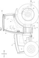
FIG. 1 is a side view showing the entirety of a tractor. -
FIG. 2 is a schematic view showing a motive power transmission device. -
FIG. 3 is a side view showing a front-wheel power transmission unit. -
FIG. 4 is a cross-sectional view taken along the line IV-IV inFIG. 3 . -
FIG. 5 is a cross-sectional view taken along the line V-V inFIG. 3 . -
FIG. 6 is a side view showing a first gear cover, a second gear cover, and a clutch cover. -
FIG. 7 is a front view showing the first gear cover. -
FIG. 8 is a perspective view showing a first equal-speed split cover, the clutch cover, and a first speed-increasing split cover in a disassembled state. -
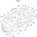
FIG. 9 is a perspective view showing a second equal-speed split cover, a second speed-increasing split cover, and a bottom wall. - Hereinafter, an embodiment of a tractor that is an example of a work vehicle according to the present invention will be described based on the drawings. In the embodiment, a front-rear direction with respect to a travel body of the tractor is defined as the direction in which the body travels in a working state thereof, and a left-right direction with respect to the body is defined as the left-right direction seen in the direction in which the body travels. Specifically, the direction indicated by the reference sign (F) in
FIG. 1 is the forward direction with respect to the body, the direction indicated by the reference sign (B) inFIG. 1 is the rear ward direction with respect to the body, the direction indicated by the reference sign (U) inFIG. 1 is the upward direction with respect to the body, and the direction indicated by the reference sign (D) inFIG. 1 is the downward direction with respect to the body. The front side of the sheet ofFIG. 1 corresponds to the left side of the body, and the back side of the sheet ofFIG. 1 corresponds to the right side of the body. Therefore, the left-right direction with respect to the body corresponds to the width direction of the body. -
FIG. 1 shows a tractor. This tractor includes atravel body 3 that is supported by a pair of left and right front wheels 1 (travel devices) that are steerable and drivable, and pair of left and right rear wheels 2 (travel devices) that are steerable. A prime mover 5 that includes anengine 4 is provided in a front section of thetravel body 3. Adriving section 6 on which an operator boards and operates the vehicle, and a linkage mechanism 7 that couples work devices such as a rotary tillage device with each other so that the work devices can be raised and lowered, are provided in a rear section of thetravel body 3. Thedriving section 6 includes a driver's seat 8, asteering wheel 9 for steering thefront wheels 1, and acabin 10 that covers the boarding space.Body frames 11 of thetravel body 3 are constituted by theengine 4, atransmission case 12 whose front section is coupled to a rear section of theengine 4, front-wheel support frames 13 coupled to a lower section of theengine 4, and so on. APTO shaft 14 that transmits motive power from theengine 4 to the work devices coupled to each other by the linkage mechanism 7 is provided in a rear section of thetransmission case 12. - As shown in
FIG. 2 , a motivepower transmission device 15 for travel, which transmits motive power to thefront wheels 1 and therear wheels 2, includes atransmission 18 that shifts and transmits the motive power from theengine 4, which serves as a motive power source, to a rear wheeldifferential mechanism 16 and a front wheeldifferential mechanism 17. Thetransmission 18 is housed in thetransmission case 12. - As shown in
FIG. 3 , thetransmission 18 includes aninput shaft 20 to which motive power from anoutput shaft 4a of theengine 4 is transmitted via amain clutch 19, amain transmission unit 21 to which motive power from theinput shaft 20 is input, and that shifts and outputs the input motive power, a stepwisepower transmission unit 22 to which the output from themain transmission unit 21 is input, a forward and rearwardtravel switching device 23 to which the output from the stepwisepower transmission unit 22 is input, agear interlocking mechanism 24 that transmits the output from the forward and rearwardtravel switching device 23 to aninput shaft 16a of the rear wheeldifferential mechanism 16, and a front-wheelpower transmission unit 25 to which the output from the forward and rearwardtravel switching device 23 is input. - As shown in
FIG. 2 , themain transmission unit 21 includes a continuouslyvariable transmission device 28 to which motive power from theinput shaft 20 is input via arotation shaft 26 and agear interlocking mechanism 27, and aplanetary transmission device 31 to which motive power from theinput shaft 20 is input via agear interlocking mechanism 29 and to which the output from the continuouslyvariable transmission device 28 is input via agear interlocking mechanism 30. - The continuously
variable transmission device 28 includes a variable displacement hydraulic pump P to which motive power from theinput shaft 20 is input via therotation shaft 26 and thegear interlocking mechanism 27, and a hydraulic motor M that is driven by pressure oil from the hydraulic pump P. By changing the swash plate angle of the hydraulic pump P, the continuouslyvariable transmission device 28 shifts the motive power from theinput shaft 20 into forward rotation motive power or reverse rotation motive power, steplessly changes the rotation speed of the forward rotation motive power or the reverse rotation motive power, and output the motive power from the hydraulic pump P. The continuouslyvariable transmission device 28 is formed as a hydraulic static continuously variable transmission device. - The
planetary transmission device 31 includes a firstplanetary transmission unit 31a to which the motive power from theinput shaft 20 is input via thegear interlocking mechanism 29, and to which the output from the continuouslyvariable transmission device 28 is input via thegear interlocking mechanism 30, and a secondplanetary transmission unit 31b that is interlocked with the firstplanetary transmission unit 31a. The interlocking of the firstplanetary transmission unit 31a and the secondplanetary transmission unit 31b is realized by the planetary gear of the firstplanetary transmission unit 31a and the planetary gear of the secondplanetary transmission unit 31b interlocking with each other. Theplanetary transmission device 31 is formed as a combined planetary transmission device. - In the
main transmission unit 21, the continuouslyvariable transmission device 28 shifts the motive power from theengine 4 into forward rotation motive power or reverse rotation motive power and steplessly changes the rotation speed of the forward rotation motive power or reverse rotation motive power, and the output from the continuouslyvariable transmission device 28 and the motive power from theengine 4 are combined with each other by the firstplanetary transmission unit 31a and the secondplanetary transmission unit 31b in theplanetary transmission device 31, and the combined motive power is output from threeoutput shafts - The stepwise
power transmission unit 22 includes a firstgear interlocking mechanism 33a that is coupled to thefirst output shaft 32a of the threeoutput shaft planetary transmission device 31, a secondgear interlocking mechanism 33b that is coupled to thethird output shaft 32c of the threeoutput shaft gear interlocking mechanism 33c that is coupled to thesecond output shaft 32b of the threeoutput shaft gear interlocking mechanism 33d that is coupled to thethird output shaft 32c of the threeoutput shaft gear interlocking mechanism 33a is configured to be interlocked with and coupled to theoutput shaft 34 via a first clutch CL1. The secondgear interlocking mechanism 33b is configured to be interlocked with and coupled to theoutput shaft 34 via a second clutch CL2. The thirdgear interlocking mechanism 33c is configured to be interlocked with and coupled to theoutput shaft 34 via a third clutch CL3. The fourthgear interlocking mechanism 33d is configured to be interlocked with and coupled to theoutput shaft 34 via a fourth clutch CL4. - In the stepwise
power transmission unit 22, when the first clutch CL1 is engaged, the continuouslyvariable transmission device 28 is shifted and the steplessly shifted output from theplanetary transmission device 31 is output from theoutput shaft 34 as motive power that has been shifted steplessly in a first speed range. When the second clutch CL2 is engaged, the continuouslyvariable transmission device 28 is shifted and the steplessly shifted output from theplanetary transmission device 31 is output from theoutput shaft 34 as motive power that has been shifted steplessly in a second speed range that is higher than the first speed range. When the third clutch CL3 is engaged, the continuouslyvariable transmission device 28 is shifted and the steplessly shifted output from theplanetary transmission device 31 is output from theoutput shaft 34 as motive power that has been shifted steplessly in a third speed range that is higher than the second speed range. When the fourth clutch CL4 is engaged, the continuouslyvariable transmission device 28 is shifted and the steplessly shifted output from theplanetary transmission device 31 is output from theoutput shaft 34 as motive power that has been shifted steplessly in a fourth speed range that is higher than the third speed range. - The forward and rearward
travel switching device 23 includes aninput shaft 23a that is coupled to theoutput shaft 34 of the stepwisepower transmission unit 22, and a forward travel clutch CLF and a rearward travel clutch CLR that are provided on theinput shaft 23a. - The forward travel clutch CLF is configured to be interlocked with and coupled to an
output shaft 23b via a forward travelgear interlocking mechanism 35f. The rearward travel clutch CLR is configured to be interlocked with and coupled to theoutput shaft 23b via a rearward travelgear interlocking mechanism 35r. - In the forward and rearward
travel switching device 23, the output from the stepwisepower transmission unit 22 is input to theinput shaft 23a, and when the forward travel clutch CLF is engaged, the motive power from theinput shaft 23a is converted by the forward travelgear interlocking mechanism 35f to forward travel power, which is output from theoutput shaft 23b, and when the rearward travel clutch CLR is engaged, the motive power from theinput shaft 23a is converted by the rearward travelgear interlocking mechanism 35r to rearward travel power, which is output from theoutput shaft 23b. The forward travel power and the rearward travel power output from theoutput shaft 23b are input by thegear interlocking mechanism 24 to the rearwheel differential mechanism 16 and the front-wheelpower transmission unit 25. - In the rear
wheel differential mechanism 16, the input motive power is transmitted from left andright output shafts 16b to the left and rightrear wheels 2. The motive power from theleft output shaft 16b is transmitted to the leftrear wheel 2 via aplanetary deceleration mechanism 36. Theleft output shaft 16b is provided with a steeringbrake 37. Although not shown, the power transmission system from theright output shaft 16b to the rightrear wheel 2 is provided with theplanetary deceleration mechanism 36 and the steeringbrake 37, as with the power transmission system to the leftrear wheel 2. - As shown in
FIGS. 3 and4 , the front-wheelpower transmission unit 25 is provided in abottom section 12d of the internal space of thetransmission case 12. As shown inFIG. 2 , the front-wheelpower transmission unit 25 includes aninput shaft 25a that is coupled to anoutput shaft 24a of thegear interlocking mechanism 24, and anoutput shaft 25b that is parallel with theinput shaft 25a. Theinput shaft 25a and theoutput shaft 25b are provided in such a manner as to extend in the front-rear direction of the transmission case 12 (the front-rear direction with respect to the body), and theoutput shaft 25b is at a lower position than theinput shaft 25a with respect to the transmission case (with respect to the body of the tractor). Theoutput shaft 24a of thegear interlocking mechanism 24 is provided with aparking brake 38. - As shown in
FIG. 2 , theinput shaft 25a is provided with an equal-speed clutch CLT and a speed-increasing clutch CLH that is rearward of the equal-speed clutch CLT with respect to the transmission case. - An equal-
speed gear pair 39 is provided over the equal-speed clutch CLT and theoutput shaft 25b. The equal-speed gear pair 39 includes a first equal-speedpower transmission gear 39a and a second equal-speedpower transmission gear 39b, where the first equal-speedpower transmission gear 39a is coupled to an output-side member of the equal-speed clutch CLT and is rotatable about a first rotation axis X1, which is the axis of theinput shaft 25a, and the second equal-speedpower transmission gear 39b is provided on theoutput shaft 25b, meshes with the first equal-speedpower transmission gear 39a, and is rotatable about a second rotation axis X2, which is the axis of theoutput shaft 25b. The equal-speed gear pair 39 is configured to realize an equal-speed power transmission state in which the peripheral speed of thefront wheels 1 is equal to the peripheral speed of therear wheels 2, by controlling the power transmission gear ratio between the first equal-speedpower transmission gear 39a and the second equal-speedpower transmission gear 39b. - A speed-increasing
gear pair 40 is provided over the speed-increasing clutch CLH and theoutput shaft 25b. The speed-increasinggear pair 40 includes a first speed-increasingpower transmission gear 40a and a second speed-increasingpower transmission gear 40b, where the first speed-increasingpower transmission gear 40a is coupled to an output-side member of the speed-increasing clutch CLH and is rotatable about the first rotation axis X1, which is the axis of theinput shaft 25a, and the second speed-increasingpower transmission gear 40b is provided on theoutput shaft 25b, meshes with the first speed-increasingpower transmission gear 40a, and is rotatable about the second rotation axis X2, which is the axis of theoutput shaft 25b. The speed-increasinggear pair 40 is configured to realize a front-wheel speed-increasing power transmission state in which the peripheral speed of thefront wheels 1 is higher than the peripheral speed of therear wheels 2 by controlling the power transmission gear ratio between the first speed-increasingpower transmission gear 40a and the second speed-increasingpower transmission gear 40b. - As shown in
FIGS. 3 ,4 , and5 , the first equal-speedpower transmission gear 39a, the second equal-speedpower transmission gear 39b, the first speed-increasingpower transmission gear 40a, and the second speed-increasingpower transmission gear 40b are provided in thebottom section 12d of the internal space of thetransmission case 12. The first equal-speedpower transmission gear 39a and the second equal-speedpower transmission gear 39b are covered by afirst gear cover 41, and the first speed-increasingpower transmission gear 40a and the second speed-increasingpower transmission gear 40b are covered by asecond gear cover 42. - In the front-wheel
power transmission unit 25, when the equal-speed clutch CLT is engaged, the motive power from theinput shaft 25a is transmitted by the equal-speed clutch CLT and the equal-speed gear pair 39 to theoutput shaft 25b, the equal-speed gear pair 39 realizes an equal-speed power transmission state, and motive power that drives thefront wheels 1 is output from theoutput shaft 25b so that the peripheral speed of thefront wheels 1 is equal to the peripheral speed of therear wheels 2. When the speed-increasing clutch CLH is engaged, the motive power from theinput shaft 25a is transmitted by the speed-increasing clutch CLH and the speed-increasinggear pair 40 to theoutput shaft 25b, the speed-increasinggear pair 40 realizes a front-wheel speed-increasing power transmission state, and motive power that drives thefront wheels 1 is output from theoutput shaft 25b so that the peripheral speed of thefront wheels 1 is higher than the peripheral speed of therear wheels 2. The output from theoutput shaft 25b is input to the frontwheel differential mechanism 17 via arotation shaft 43 that couples theoutput shaft 25b and aninput shaft 17a of the frontwheel differential mechanism 17. - In the
travel body 3, when the equal-speed clutch CLT is engaged, a four-wheel drive state in which thefront wheels 1 and therear wheels 2 are driven so that the average peripheral speed of the left and rightfront wheels 1 is equal to the average peripheral speed of the left and rightrear wheels 2 is realized, and when the speed-increasing clutch CLH is engaged, a four-wheel drive state in which thefront wheels 1 and therear wheels 2 are driven so that the average peripheral speed of the left and rightfront wheels 1 is higher than the average peripheral speed of the left and rightrear wheels 2 is realized. As a result, when the speed-increasing clutch CLH is engaged, thetravel body 3 is enabled to turn with a smaller turning radius than when the equal-speed clutch CLT is engaged. - When the equal-speed clutch CLT is engaged, the first equal-speed
power transmission gear 39a and the second equal-speedpower transmission gear 39b are rotated by the motive power from theinput shaft 25a, and the first speed-increasingpower transmission gear 40a and the second speed-increasingpower transmission gear 40b are rotated by the motive power from theoutput shaft 25b. When the speed-increasing clutch CLH is engaged, the first speed-increasingpower transmission gear 40a and the second speed-increasingpower transmission gear 40b are rotated by the motive power from theinput shaft 25a, and the first equal-speedpower transmission gear 39a and the second equal-speedpower transmission gear 39b are rotated by the motive power from theoutput shaft 25b. Although the lubricating oil stored in thetransmission case 12 is agitated by the first equal-speedpower transmission gear 39a, the second equal-speedpower transmission gear 39b, the first speed-increasingpower transmission gear 40a, and the second speed-increasingpower transmission gear 40b, thefirst gear cover 41 prevents the agitation of the lubricating oil by the first equal-speedpower transmission gear 39a and the second equal-speedpower transmission gear 39b from spreading into the lubricating oil storage area. Thesecond gear cover 42 prevents the agitation of the lubricating oil by the first speed-increasingpower transmission gear 40a and the second speed-increasingpower transmission gear 40b from spreading into the lubricating oil storage area. - As shown in
FIGS. 3 ,4 ,6 , and7 , thefirst gear cover 41 is split into a first equal-speed split cover 41A that covers the first equal-speedpower transmission gear 39a and a second equal-speed split cover 41B that covers the second equal-speedpower transmission gear 39b. As shown inFIGS. 3 ,5 , and6 , thesecond gear cover 42 is split into a first speed-increasingsplit cover 42A that covers the first speed-increasingpower transmission gear 40a and a second speed-increasingsplit cover 42B that covers the second speed-increasingpower transmission gear 40b. - As shown in
FIGS. 3 ,4 ,6 ,7 , and8 , the first equal-speed split cover 41A includes afront cover section 44 that covers the first equal-speedpower transmission gear 39a from the front side, and acircumference cover section 45 that covers the first equal-speedpower transmission gear 39a from the outer circumference thereof. The outer peripheral edge of thefront cover portion 44 and the front end of thecircumference cover section 45 are coupled to each other. Thefront cover section 44 and thecircumference cover section 45 are coupled through welding. A lower section of thecircumference cover section 45 is provided with anopening 46 from which a lower section of the first equal-speedpower transmission gear 39a protrudes toward the second equal-speedpower transmission gear 39b. - As shown in
FIGS. 3 ,5 ,6 , and8 , the first speed-increasingsplit cover 42A includes arear cover section 48 that covers the first speed-increasingpower transmission gear 40a from the rear side, and acircumference cover section 49 that covers the first speed-increasingpower transmission gear 40a from the outer circumference thereof. Thecircumference cover section 49 is integrated with a rear end of aclutch cover 50 that covers the equal-speed clutch CLT and the speed-increasing clutch CLH from the outer circumferences thereof. The rear end of thecircumference cover section 49 and the outer peripheral edge of therear cover section 48 are coupled to each other. The coupling of thecircumference cover section 49 and therear cover section 48 to each other is realized by coupling front-rear coupling bolts 51 (seeFIGS. 6 and8 ), which is provided for thecircumference cover section 49, to therear cover section 48. A lower section of thecircumference cover section 49 is provided with anopening 52 from which a lower section of the first speed-increasingpower transmission gear 40a protrudes toward the second speed-increasingpower transmission gear 40b. - As shown in
FIGS. 3 and6 , anattachment hole 44a (seeFIG. 8 ), which is provided in thefront cover section 44 of the first equal-speed split cover 41A, is fitted onto abearing 53 that supports a front section of theinput shaft 25a, and the first equal-speed split cover 41A is supported by thebearing 53. An attachment cylinder section 54 (seeFIG. 8 ), which is provided in therear cover section 48 of the first speed-increasingsplit cover 42A, is fitted onto abearing 55 that supports a rear section of theinput shaft 25a, and the first speed-increasingsplit cover 42A is supported by thebearing 55. As shown inFIG. 3 , acoupling bolt 56 couples acoupling section 50a (seeFIG. 8 ), which is provided on an upper section of theclutch cover 50, to a supportingsection 12a, which is provided in thetransmission case 12. As shown inFIG. 6 , a coupling bolt 47 (seeFIG. 8 ) couples the first equal-speed split cover 41A and theclutch cover 50 to each other, and theclutch cover 50 prevents the first equal-speed split cover 41A from being rotated and positions the first equal-speed split cover 41A with respect to the first equal-speedpower transmission gear 39a in the direction along the first rotation axis X1. The first speed-increasingsplit cover 42A and theclutch cover 50 are coupled to each other, and theclutch cover 50 prevents the first speed-increasingsplit cover 42A from being rotated, and positions the first speed-increasingsplit cover 42A with respect to the first speed-increasingpower transmission gear 40a in the direction along the first rotation axis X1. - As shown in
FIGS. 3 ,4 ,6 ,7 , and9 , the second equal-speed split cover 41B includes afront cover section 57 that covers the second equal-speedpower transmission gear 39b from the front side, arear cover section 58 that covers the second equal-speedpower transmission gear 39b from the rear side, and acircumference cover section 59 that covers the second equal-speedpower transmission gear 39b from the outer circumference thereof. Thefront cover section 57 is provided with a throughhole 57a into which theoutput shaft 25b is inserted, and therear cover section 58 is provided with acutout 58a through which theoutput shaft 25b is inserted. An upper section of thecircumference cover section 59 is provided with anopening 60 from which an upper section of the second equal-speedpower transmission gear 39b protrudes toward the first equal-speedpower transmission gear 39a. - As shown in
FIGS. 3 ,4 ,5 ,6 , and9 , the second speed-increasingsplit cover 42B includes afront cover section 61 that covers the second speed-increasingpower transmission gear 40b from the front side, arear cover section 62 that covers the second speed-increasingpower transmission gear 40b from the rear side, and acircumference cover section 63 that covers the second speed-increasingpower transmission gear 40b from the outer circumference thereof. Thefront cover section 61 is provided with acutout 61a into which theoutput shaft 25b is inserted, and therear cover section 62 is provided with a throughhole 62a through which theoutput shaft 25b is inserted. An upper section of thecircumference cover section 63 is provided with anopening 64 from which an upper section of the second speed-increasingpower transmission gear 40b protrudes toward the first speed-increasingpower transmission gear 40a. - As shown in
FIG. 3 ,6 ,9 , and so on, the second equal-speed split cover 41B and the second speed-increasingsplit cover 42B are supported by abottom wall 65 of thetransmission case 12. The second equal-speed split cover 41B and the second speed-increasingsplit cover 42B are supported by thebottom wall 65 in such a manner that the second equal-speed split cover 41B and the second speed-increasingsplit cover 42B are integrated with thebottom wall 65. As shown inFIGS. 4 ,5 ,6 , and9 , thebottom wall 65 is at a position between therear cover section 58 of the second equal-speed split cover 41B and thefront cover section 61 of the second speed-increasingsplit cover 42B, and includes acoupling section 65c that couples therear cover section 58 and thefront cover section 61 to each other, and ahorizontal section 65d that is connected to an upper section of thecoupling section 65c and has aflange 66. Thecoupling section 65c has an internal space through which theoutput shaft 25b passes. The width of thecoupling section 65c is smaller than the outer diameter of the second equal-speed split cover 41B and the second speed-increasingsplit cover 42B. - The
bottom wall 65 is configured to be detachable from aclutch housing 12c of abody 12b of thetransmission case 12. Theclutch housing 12c houses the equal-speed clutch CLT and the speed-increasing clutch CLH. Specifically, as shown inFIGS. 5 ,6 ,9 , and so on, thebottom wall 65 has theflange 66 provided on an upper section of thebottom wall 65, and coupling bolts 67 (seeFIG. 7 ), which are inserted from below intocoupling holes 66a (seeFIG. 9 ) provided at multiple positions in theflange 66, engage with theclutch housing 12c, and accordingly thebottom wall 65 is coupled to theclutch housing 12c of thebody 12b by thecoupling bolts 67. - As shown in
FIGS. 3 and6 , thebottom wall 65 includes a front supportingsection 65a into which a front section of theoutput shaft 25b is inserted via abearing 68, and arear supporting section 65b into which a rear section of theoutput shaft 25b is inserted via abearing 68, and thebottom wall 65 is configured so that the front supportingsection 65a and therear supporting section 65b support theoutput shaft 25b. Theoutput shaft 25b is supported by thebottom wall 65. With this configuration, the second speed-increasingsplit cover 42B positions the second speed-increasingpower transmission gear 40b and the second equal-speedpower transmission gear 39b with respect to a rear section of thebottom wall 65, and the second equal-speed split cover 41B positions the second speed-increasingpower transmission gear 40b and the second equal-speedpower transmission gear 39b with respect to a front section of thebottom wall 65. In addition, the second equal-speed split cover 41B is positioned with respect to the second equal-speedpower transmission gear 39b in the direction along the second rotation axis X2, and the second speed-increasingsplit cover 42B is positioned with respect to the second speed-increasingpower transmission gear 40b in the direction along the second rotation axis X2. It is possible to attach the second equal-speedpower transmission gear 39b, the second speed-increasingpower transmission gear 40b, the second equal-speed split cover 41B, and the second speed-increasingsplit cover 42B to thetransmission case 12 by attaching thebottom wall 65 to thebody 12b. - (1) Although the above embodiment describes an example in which the
front wheels 1 and therear wheels 2 are provided, a crawler travel device or a mini crawler may be employed as a travel device. - (2) Although the above embodiment describes an example in which the equal-
speed gear pair 39 and the speed-increasinggear pair 40 are provided as a gear pair, the present invention is not limited to such a configuration, and a gear pair that transmits motive power only to therear wheels 2 or a gear pair that simply transmits motive power without changing the transmission speed thereof may be employed. - (3) Although the above embodiment describes an example in which the
first gear cover 41 can be split into the first equal-speed split cover 41A and the second equal-speed split cover 41B and thesecond gear cover 42 can be split into the first speed-increasingsplit cover 42A and the second speed-increasingsplit cover 42B, the present invention is not limited to such a configuration, and unsplittable cover may be employed. - (4) Although the above embodiment describes an example in which the second equal-
speed split cover 41B and the second speed-increasingsplit cover 42B are integrated with thebottom wall 65, split covers that are separate from thebottom wall 65 and are not supported by thebottom wall 65, or split covers that are separate from thebottom wall 65 and are supported by thebottom wall 65 may be employed. - (5) Although the above embodiment describes an example in which the
bottom wall 65 is detachable from theclutch housing 12c, a bottom wall that is integrated with theclutch housing 12c and cannot be detached from theclutch housing 12c may be employed. - (6) Although the above embodiment describes an example in which the motive power source is the
engine 4, an electric motor may be employed as a power source. - (7) The present invention is applicable to a transmission that outputs power to a travel device, and a work vehicle provided with a transmission case that houses the transmission.
-
- 1 Front Wheel (Travel Device)
- 2 Rear Wheel (Rear Travel Device)
- 4 Engine (Motive Power Source)
- 12 Transmission Case
- 12b Body
- 12d Bottom Section
- 18 Transmission
- 25 Front-Wheel Power Transmission Unit
- 39 Equal-Speed Gear Pair (Gear Pair)
- 39a First Equal-Speed Power Transmission Gear (First Power Transmission Gear)
- 39b Second Equal-Speed Power Transmission Gear (Second Power Transmission Gear)
- 40 Speed-Increasing Gear Pair (Gear Pair)
- 40a First Speed-Increasing Power Transmission Gear (First Power Transmission Gear)
- 40b Second Speed-Increasing Power Transmission Gear (Second Power Transmission Gear)
- 41 First Gear Cover (Gear Cover)
- 41A First Equal-Speed Split Cover (First Split Cover)
- 41B Second Equal-Speed Split Cover (Second Split Cover)
- 42 Second Gear Cover (Gear Cover)
- 42A First Speed-Increasing Split Cover (First Split Cover)
- 42B Second Speed-Increasing Split Cover (Second Split Cover)
- 65 Bottom Wall
Claims (5)
- A work vehicle comprising:a transmission (18) configured to receive motive power input from a motive power source (4), and shift and output the input motive power to a travel device (1);a transmission case (12) housing the transmission (18); andat least one gear pair (39, 40) disposed in the transmission (18), in a bottom section (12d) of an internal space of the transmission case (12), and including (i) a first power transmission gear (40a) configured to rotate about a first rotation axis, and (ii) a second power transmission gear (40b) configured to mesh with the first power transmission gear (40a) and rotate about a second rotation axis parallel with the first rotation axis,wherein the work vehicle further comprises at least one gear cover (41, 42) covering the first power transmission gear (40a) and the second power transmission gear (40b).
- The work vehicle according to claim 1,
wherein the at least one gear cover (41) is configured to be splittable into a first split cover (41A, 42A) covering the first power transmission gear (40a) and a second split cover (41B, 42B) covering the second power transmission gear (40b). - The work vehicle according to claim 2,
wherein the second split cover (41B, 42B) is integrated with a bottom wall (65) of the transmission case (12). - The work vehicle according to claim 3,
wherein the bottom wall (65) is configured to be detachable from a body (12b) of the transmission case (12). - The work vehicle according to any one of claims 1 to 4,wherein the travel device (1) includes a front wheel (1) and a rear travel device (2),the transmission (18) includes a front-wheel power transmission unit (25) configured to be switchable to (i) an equal-speed power transmission state, in which the front-wheel power transmission unit (25) transmits motive power to the front wheel (1) in such a manner that a peripheral speed of the front wheel (1) is equal to a peripheral speed of the rear travel device (2), and (ii) a speed-increasing power transmission state, in which the front-wheel power transmission unit (25) transmits motive power to the front wheel (1) in such a manner that the peripheral speed of the front wheel (1) is higher than the peripheral speed of the rear travel device (2),the at least one gear pair includes a gear pair (39) disposed in the front-wheel power transmission unit and configured to realize the equal-speed power transmission state, and a gear pair disposed in the front-wheel power transmission unit (25) and configured to realize the speed-increasing power transmission state, andthe at least one gear cover (41, 42) includes a gear cover (41) covering the gear pair (39) configured to realize the equal-speed power transmission state, and a gear cover (42) covering the gear pair (40) configured to realize the speed-increasing power transmission state.
Applications Claiming Priority (1)
| Application Number | Priority Date | Filing Date | Title |
|---|---|---|---|
| JP2022101759A JP7797318B2 (en) | 2022-06-24 | 2022-06-24 | Work vehicle |
Publications (2)
| Publication Number | Publication Date |
|---|---|
| EP4296544A1 true EP4296544A1 (en) | 2023-12-27 |
| EP4296544B1 EP4296544B1 (en) | 2025-09-03 |
Family
ID=86185215
Family Applications (1)
| Application Number | Title | Priority Date | Filing Date |
|---|---|---|---|
| EP23169553.7A Active EP4296544B1 (en) | 2022-06-24 | 2023-04-24 | Work vehicle |
Country Status (3)
| Country | Link |
|---|---|
| US (1) | US12404926B2 (en) |
| EP (1) | EP4296544B1 (en) |
| JP (1) | JP7797318B2 (en) |
Citations (8)
| Publication number | Priority date | Publication date | Assignee | Title |
|---|---|---|---|---|
| US2017871A (en) * | 1932-04-01 | 1935-10-22 | Hoe & Co R | Lubricant spreader for gears |
| US4683771A (en) * | 1980-08-20 | 1987-08-04 | Toyota Jidosha Kogyo Kabushiki Kaisha | Gear-teeth protector in change-speed gearing units |
| EP2700849A1 (en) * | 2011-04-20 | 2014-02-26 | Toyota Jidosha Kabushiki Kaisha | Lubricating oil supply device for power transmission device |
| JP2019095058A (en) | 2017-11-24 | 2019-06-20 | 株式会社クボタ | Tractor gear change transmission device and tractor |
| US20210071740A1 (en) * | 2017-06-22 | 2021-03-11 | Kubota Corporation | Work Vehicle Transmission and Work Vehicle Having the Same |
| EP3798468A2 (en) * | 2019-09-26 | 2021-03-31 | Kubota Corporation | Traveling transmission device of tractor |
| US11028917B1 (en) * | 2020-02-11 | 2021-06-08 | Deere & Company | Work equipment transmission with gear baffle and method of assembly |
| US20220153132A1 (en) * | 2019-04-17 | 2022-05-19 | Kubota Corporation | Traveling transmission device for tractor |
Family Cites Families (24)
| Publication number | Priority date | Publication date | Assignee | Title |
|---|---|---|---|---|
| GB182298A (en) * | 1921-06-02 | 1922-07-06 | Richard Henry Dickinson | Improvements in the gear cases of tram cars |
| GB292540A (en) * | 1927-06-21 | 1928-09-06 | Gen Electric | Improvements in or relating to lubricating devices for gear wheels |
| US2292086A (en) * | 1940-10-29 | 1942-08-04 | Gen Electric | Gear drive and lubrication system |
| US2487782A (en) * | 1945-07-17 | 1949-11-15 | Koehring Co | Automatic gear lubricating means |
| GB1426352A (en) * | 1973-02-09 | 1976-02-25 | Holmes Co Ltd W C | Gear lubrication device |
| US4347759A (en) * | 1979-08-30 | 1982-09-07 | Renk Richard J | Gear case |
| DE3334411C1 (en) * | 1983-09-23 | 1984-10-18 | Ford-Werke AG, 5000 Köln | Gearboxes in countershaft construction, especially for motor vehicles |
| JP2852167B2 (en) * | 1993-01-18 | 1999-01-27 | ダイハツ工業株式会社 | Power transmission lubrication system |
| JPH06249323A (en) * | 1993-02-25 | 1994-09-06 | Kubota Corp | Mission oil temperature rise suppression device for traveling vehicle |
| FR2805019B1 (en) * | 2000-02-10 | 2002-05-17 | Peugeot Citroen Automobiles Sa | MANUAL GEARBOX FOR MOTOR VEHICLE |
| JP2003260950A (en) * | 2002-03-06 | 2003-09-16 | Iseki & Co Ltd | Powered vehicle |
| JP4616321B2 (en) * | 2007-10-18 | 2011-01-19 | 株式会社クボタ | Transmission device for traveling vehicle |
| JP5013194B2 (en) * | 2007-10-22 | 2012-08-29 | 株式会社ジェイテクト | Vehicle steering system |
| JP5738004B2 (en) * | 2011-03-01 | 2015-06-17 | マツダ株式会社 | Interposition member holding structure, interposition member, and rattling prevention member |
| SE537950C2 (en) * | 2012-10-17 | 2015-12-01 | Scania Cv Ab | Gear steering gear, gearbox comprising one such steering gear and vehicle including such gearbox |
| KR101776921B1 (en) * | 2015-10-13 | 2017-09-11 | 한국기계연구원 | An Extra-large excavator hydraulic pump drive gear box lubrication and noise attenuation devices |
| DE102017211749B4 (en) * | 2017-07-10 | 2025-05-08 | Zf Friedrichshafen Ag | Power-split axle drive for a working machine and working machine |
| JP2019143744A (en) * | 2018-02-22 | 2019-08-29 | トヨタ自動車株式会社 | Drive unit |
| US11940043B2 (en) | 2018-05-17 | 2024-03-26 | Jatco Ltd | Baffle plate and seal member of a driving force transmission device |
| JP6922878B2 (en) * | 2018-11-28 | 2021-08-18 | 井関農機株式会社 | Work vehicle and shift control method for work vehicle |
| KR102852654B1 (en) * | 2020-07-23 | 2025-08-29 | 현대모비스 주식회사 | In-wheel driving apparatus |
| JP7499692B2 (en) * | 2020-12-17 | 2024-06-14 | 株式会社クボタ | Work vehicle |
| US11994201B2 (en) * | 2020-12-28 | 2024-05-28 | Kubota Corporation | Power transmission device for work vehicle |
| JP7504060B2 (en) * | 2021-06-15 | 2024-06-21 | 株式会社クボタ | Power transmission device for work vehicles |
-
2022
- 2022-06-24 JP JP2022101759A patent/JP7797318B2/en active Active
-
2023
- 2023-04-21 US US18/137,492 patent/US12404926B2/en active Active
- 2023-04-24 EP EP23169553.7A patent/EP4296544B1/en active Active
Patent Citations (8)
| Publication number | Priority date | Publication date | Assignee | Title |
|---|---|---|---|---|
| US2017871A (en) * | 1932-04-01 | 1935-10-22 | Hoe & Co R | Lubricant spreader for gears |
| US4683771A (en) * | 1980-08-20 | 1987-08-04 | Toyota Jidosha Kogyo Kabushiki Kaisha | Gear-teeth protector in change-speed gearing units |
| EP2700849A1 (en) * | 2011-04-20 | 2014-02-26 | Toyota Jidosha Kabushiki Kaisha | Lubricating oil supply device for power transmission device |
| US20210071740A1 (en) * | 2017-06-22 | 2021-03-11 | Kubota Corporation | Work Vehicle Transmission and Work Vehicle Having the Same |
| JP2019095058A (en) | 2017-11-24 | 2019-06-20 | 株式会社クボタ | Tractor gear change transmission device and tractor |
| US20220153132A1 (en) * | 2019-04-17 | 2022-05-19 | Kubota Corporation | Traveling transmission device for tractor |
| EP3798468A2 (en) * | 2019-09-26 | 2021-03-31 | Kubota Corporation | Traveling transmission device of tractor |
| US11028917B1 (en) * | 2020-02-11 | 2021-06-08 | Deere & Company | Work equipment transmission with gear baffle and method of assembly |
Also Published As
| Publication number | Publication date |
|---|---|
| JP2024002523A (en) | 2024-01-11 |
| US12404926B2 (en) | 2025-09-02 |
| JP7797318B2 (en) | 2026-01-13 |
| EP4296544B1 (en) | 2025-09-03 |
| US20230417313A1 (en) | 2023-12-28 |
Similar Documents
| Publication | Publication Date | Title |
|---|---|---|
| US8657713B2 (en) | Power train for work vehicle | |
| US9945464B2 (en) | Transmission apparatus | |
| EP3715673A1 (en) | Tractor variable speed transmission device and tractor | |
| US4523493A (en) | Transmission gear for transverse mounting and motor vehicle with transmission gear mounted therein | |
| US11261951B2 (en) | Shift power transmission apparatus of a tractor and tractor | |
| EP4202259A1 (en) | Work vehicle | |
| JP2007022379A (en) | Work carrying vehicle | |
| US11994201B2 (en) | Power transmission device for work vehicle | |
| US20220397189A1 (en) | Power transmission device for work vehicle | |
| KR101383135B1 (en) | Transmission | |
| EP4296544B1 (en) | Work vehicle | |
| US6821225B2 (en) | Transmission apparatus for a working vehicle | |
| US7712573B2 (en) | Working vehicle | |
| JP2009092169A (en) | Work machine transmission case structure | |
| JP7561612B2 (en) | Power transmission device for work vehicles | |
| JP7519958B2 (en) | Power transmission device for work vehicles | |
| EP4477444A1 (en) | Work vehicle | |
| JP6904323B2 (en) | Work vehicle | |
| JP3959904B2 (en) | Mounting structure of hydrostatic continuously variable transmission for work vehicle | |
| EP3929467B1 (en) | Planetary gear device and compound planetary gear device | |
| JP4693370B2 (en) | Airframe structure in traveling work machine | |
| JP2023005474A (en) | Power transmission device for work vehicle | |
| JP2000203291A (en) | Transplanting machine | |
| WO2024142478A1 (en) | Work vehicle | |
| JP2000203283A (en) | Transplanting machine |
Legal Events
| Date | Code | Title | Description |
|---|---|---|---|
| PUAI | Public reference made under article 153(3) epc to a published international application that has entered the european phase |
Free format text: ORIGINAL CODE: 0009012 |
|
| STAA | Information on the status of an ep patent application or granted ep patent |
Free format text: STATUS: REQUEST FOR EXAMINATION WAS MADE |
|
| 17P | Request for examination filed |
Effective date: 20230424 |
|
| AK | Designated contracting states |
Kind code of ref document: A1 Designated state(s): AL AT BE BG CH CY CZ DE DK EE ES FI FR GB GR HR HU IE IS IT LI LT LU LV MC ME MK MT NL NO PL PT RO RS SE SI SK SM TR |
|
| GRAP | Despatch of communication of intention to grant a patent |
Free format text: ORIGINAL CODE: EPIDOSNIGR1 |
|
| STAA | Information on the status of an ep patent application or granted ep patent |
Free format text: STATUS: GRANT OF PATENT IS INTENDED |
|
| INTG | Intention to grant announced |
Effective date: 20250416 |
|
| RIN1 | Information on inventor provided before grant (corrected) |
Inventor name: WADA, KAZUHIRO Inventor name: AIKAWA, HIROYUKI Inventor name: MATSUO, TAKAHIRO Inventor name: TANAKA, TOMOYUKI Inventor name: TSUCHIDA, TOMONARI |
|
| GRAS | Grant fee paid |
Free format text: ORIGINAL CODE: EPIDOSNIGR3 |
|
| GRAA | (expected) grant |
Free format text: ORIGINAL CODE: 0009210 |
|
| STAA | Information on the status of an ep patent application or granted ep patent |
Free format text: STATUS: THE PATENT HAS BEEN GRANTED |
|
| AK | Designated contracting states |
Kind code of ref document: B1 Designated state(s): AL AT BE BG CH CY CZ DE DK EE ES FI FR GB GR HR HU IE IS IT LI LT LU LV MC ME MK MT NL NO PL PT RO RS SE SI SK SM TR |
|
| REG | Reference to a national code |
Ref country code: CH Ref legal event code: EP |
|
| REG | Reference to a national code |
Ref country code: DE Ref legal event code: R096 Ref document number: 602023006245 Country of ref document: DE |
|
| REG | Reference to a national code |
Ref country code: IE Ref legal event code: FG4D |
|
| REG | Reference to a national code |
Ref country code: NL Ref legal event code: MP Effective date: 20250903 |
|
| PG25 | Lapsed in a contracting state [announced via postgrant information from national office to epo] |
Ref country code: NO Free format text: LAPSE BECAUSE OF FAILURE TO SUBMIT A TRANSLATION OF THE DESCRIPTION OR TO PAY THE FEE WITHIN THE PRESCRIBED TIME-LIMIT Effective date: 20251203 |
|
| REG | Reference to a national code |
Ref country code: LT Ref legal event code: MG9D |
|
| PG25 | Lapsed in a contracting state [announced via postgrant information from national office to epo] |
Ref country code: FI Free format text: LAPSE BECAUSE OF FAILURE TO SUBMIT A TRANSLATION OF THE DESCRIPTION OR TO PAY THE FEE WITHIN THE PRESCRIBED TIME-LIMIT Effective date: 20250903 |
|
| PG25 | Lapsed in a contracting state [announced via postgrant information from national office to epo] |
Ref country code: HR Free format text: LAPSE BECAUSE OF FAILURE TO SUBMIT A TRANSLATION OF THE DESCRIPTION OR TO PAY THE FEE WITHIN THE PRESCRIBED TIME-LIMIT Effective date: 20250903 |
|
| PG25 | Lapsed in a contracting state [announced via postgrant information from national office to epo] |
Ref country code: GR Free format text: LAPSE BECAUSE OF FAILURE TO SUBMIT A TRANSLATION OF THE DESCRIPTION OR TO PAY THE FEE WITHIN THE PRESCRIBED TIME-LIMIT Effective date: 20251204 |
|
| PG25 | Lapsed in a contracting state [announced via postgrant information from national office to epo] |
Ref country code: SE Free format text: LAPSE BECAUSE OF FAILURE TO SUBMIT A TRANSLATION OF THE DESCRIPTION OR TO PAY THE FEE WITHIN THE PRESCRIBED TIME-LIMIT Effective date: 20250903 |
|
| PG25 | Lapsed in a contracting state [announced via postgrant information from national office to epo] |
Ref country code: LV Free format text: LAPSE BECAUSE OF FAILURE TO SUBMIT A TRANSLATION OF THE DESCRIPTION OR TO PAY THE FEE WITHIN THE PRESCRIBED TIME-LIMIT Effective date: 20250903 |
|
| PG25 | Lapsed in a contracting state [announced via postgrant information from national office to epo] |
Ref country code: BG Free format text: LAPSE BECAUSE OF FAILURE TO SUBMIT A TRANSLATION OF THE DESCRIPTION OR TO PAY THE FEE WITHIN THE PRESCRIBED TIME-LIMIT Effective date: 20250903 Ref country code: PL Free format text: LAPSE BECAUSE OF FAILURE TO SUBMIT A TRANSLATION OF THE DESCRIPTION OR TO PAY THE FEE WITHIN THE PRESCRIBED TIME-LIMIT Effective date: 20250903 |
|
| PG25 | Lapsed in a contracting state [announced via postgrant information from national office to epo] |
Ref country code: RS Free format text: LAPSE BECAUSE OF FAILURE TO SUBMIT A TRANSLATION OF THE DESCRIPTION OR TO PAY THE FEE WITHIN THE PRESCRIBED TIME-LIMIT Effective date: 20251203 |
|
| PG25 | Lapsed in a contracting state [announced via postgrant information from national office to epo] |
Ref country code: ES Free format text: LAPSE BECAUSE OF FAILURE TO SUBMIT A TRANSLATION OF THE DESCRIPTION OR TO PAY THE FEE WITHIN THE PRESCRIBED TIME-LIMIT Effective date: 20250903 |
|
| REG | Reference to a national code |
Ref country code: AT Ref legal event code: MK05 Ref document number: 1833378 Country of ref document: AT Kind code of ref document: T Effective date: 20250903 |
|
| PG25 | Lapsed in a contracting state [announced via postgrant information from national office to epo] |
Ref country code: NL Free format text: LAPSE BECAUSE OF FAILURE TO SUBMIT A TRANSLATION OF THE DESCRIPTION OR TO PAY THE FEE WITHIN THE PRESCRIBED TIME-LIMIT Effective date: 20250903 |
|
| PG25 | Lapsed in a contracting state [announced via postgrant information from national office to epo] |
Ref country code: SM Free format text: LAPSE BECAUSE OF FAILURE TO SUBMIT A TRANSLATION OF THE DESCRIPTION OR TO PAY THE FEE WITHIN THE PRESCRIBED TIME-LIMIT Effective date: 20250903 |
|
| PG25 | Lapsed in a contracting state [announced via postgrant information from national office to epo] |
Ref country code: AT Free format text: LAPSE BECAUSE OF FAILURE TO SUBMIT A TRANSLATION OF THE DESCRIPTION OR TO PAY THE FEE WITHIN THE PRESCRIBED TIME-LIMIT Effective date: 20250903 |
|
| PG25 | Lapsed in a contracting state [announced via postgrant information from national office to epo] |
Ref country code: IT Free format text: LAPSE BECAUSE OF FAILURE TO SUBMIT A TRANSLATION OF THE DESCRIPTION OR TO PAY THE FEE WITHIN THE PRESCRIBED TIME-LIMIT Effective date: 20250903 |
|
| PG25 | Lapsed in a contracting state [announced via postgrant information from national office to epo] |
Ref country code: IS Free format text: LAPSE BECAUSE OF FAILURE TO SUBMIT A TRANSLATION OF THE DESCRIPTION OR TO PAY THE FEE WITHIN THE PRESCRIBED TIME-LIMIT Effective date: 20260103 |
|
| PGFP | Annual fee paid to national office [announced via postgrant information from national office to epo] |
Ref country code: FR Payment date: 20260330 Year of fee payment: 4 |
|
| PG25 | Lapsed in a contracting state [announced via postgrant information from national office to epo] |
Ref country code: CZ Free format text: LAPSE BECAUSE OF FAILURE TO SUBMIT A TRANSLATION OF THE DESCRIPTION OR TO PAY THE FEE WITHIN THE PRESCRIBED TIME-LIMIT Effective date: 20250903 Ref country code: PT Free format text: LAPSE BECAUSE OF FAILURE TO SUBMIT A TRANSLATION OF THE DESCRIPTION OR TO PAY THE FEE WITHIN THE PRESCRIBED TIME-LIMIT Effective date: 20260105 |
|
| PG25 | Lapsed in a contracting state [announced via postgrant information from national office to epo] |
Ref country code: SK Free format text: LAPSE BECAUSE OF FAILURE TO SUBMIT A TRANSLATION OF THE DESCRIPTION OR TO PAY THE FEE WITHIN THE PRESCRIBED TIME-LIMIT Effective date: 20250903 Ref country code: EE Free format text: LAPSE BECAUSE OF FAILURE TO SUBMIT A TRANSLATION OF THE DESCRIPTION OR TO PAY THE FEE WITHIN THE PRESCRIBED TIME-LIMIT Effective date: 20250903 |