EP4296174B1 - Ventilsackabfüllvorrichtung - Google Patents
Ventilsackabfüllvorrichtung Download PDFInfo
- Publication number
- EP4296174B1 EP4296174B1 EP22180479.2A EP22180479A EP4296174B1 EP 4296174 B1 EP4296174 B1 EP 4296174B1 EP 22180479 A EP22180479 A EP 22180479A EP 4296174 B1 EP4296174 B1 EP 4296174B1
- Authority
- EP
- European Patent Office
- Prior art keywords
- nozzle
- filling
- suction
- valve bag
- valve
- Prior art date
- Legal status (The legal status is an assumption and is not a legal conclusion. Google has not performed a legal analysis and makes no representation as to the accuracy of the status listed.)
- Active
Links
Images


Classifications
-
- B—PERFORMING OPERATIONS; TRANSPORTING
- B65—CONVEYING; PACKING; STORING; HANDLING THIN OR FILAMENTARY MATERIAL
- B65B—MACHINES, APPARATUS OR DEVICES FOR, OR METHODS OF, PACKAGING ARTICLES OR MATERIALS; UNPACKING
- B65B1/00—Packaging fluent solid material, e.g. powders, granular or loose fibrous material, loose masses of small articles, in individual containers or receptacles, e.g. bags, sacks, boxes, cartons, cans, or jars
- B65B1/04—Methods of, or means for, filling the material into the containers or receptacles
- B65B1/18—Methods of, or means for, filling the material into the containers or receptacles for filling valve-bags
-
- B—PERFORMING OPERATIONS; TRANSPORTING
- B65—CONVEYING; PACKING; STORING; HANDLING THIN OR FILAMENTARY MATERIAL
- B65B—MACHINES, APPARATUS OR DEVICES FOR, OR METHODS OF, PACKAGING ARTICLES OR MATERIALS; UNPACKING
- B65B1/00—Packaging fluent solid material, e.g. powders, granular or loose fibrous material, loose masses of small articles, in individual containers or receptacles, e.g. bags, sacks, boxes, cartons, cans, or jars
- B65B1/04—Methods of, or means for, filling the material into the containers or receptacles
- B65B1/16—Methods of, or means for, filling the material into the containers or receptacles by pneumatic means, e.g. by suction
-
- B—PERFORMING OPERATIONS; TRANSPORTING
- B65—CONVEYING; PACKING; STORING; HANDLING THIN OR FILAMENTARY MATERIAL
- B65B—MACHINES, APPARATUS OR DEVICES FOR, OR METHODS OF, PACKAGING ARTICLES OR MATERIALS; UNPACKING
- B65B31/00—Packaging articles or materials under special atmospheric or gaseous conditions; Adding propellants to aerosol containers
- B65B31/02—Filling, closing, or filling and closing, containers or wrappers in chambers maintained under vacuum or superatmospheric pressure or containing a special atmosphere, e.g. of inert gas
- B65B31/024—Filling, closing, or filling and closing, containers or wrappers in chambers maintained under vacuum or superatmospheric pressure or containing a special atmosphere, e.g. of inert gas specially adapted for wrappers or bags
-
- B—PERFORMING OPERATIONS; TRANSPORTING
- B65—CONVEYING; PACKING; STORING; HANDLING THIN OR FILAMENTARY MATERIAL
- B65B—MACHINES, APPARATUS OR DEVICES FOR, OR METHODS OF, PACKAGING ARTICLES OR MATERIALS; UNPACKING
- B65B2210/00—Specific aspects of the packaging machine
- B65B2210/06—Sterilising or cleaning machinery or conduits
- B65B2210/08—Cleaning nozzles, funnels or guides through which articles are introduced into containers or wrappers
Definitions
- the invention relates to a valve bag filling device for filling powdery filling material into a valve bag.
- valve bag filling devices are state of the art in numerous design variants. They typically have a filling nozzle that is designed to be inserted into a valve hose of a valve bag to be filled and a conveying device with which the filling material to be filled is conveyed from a storage container through the filling nozzle into a valve bag that is seated on the filling nozzle with the valve hose. It is state of the art to provide a suction device for sucking out excess filling material, which has a suction opening that is arranged at a distance from the filling nozzle. Such a suction device is designed to suck out the filling material that gets into the ambient air during the filling process.
- a valve bag filling device is made, for example, of DE 20 2018 006 418 U1
- This valve bag filling device is a vacuum filling device in which the valve bag is arranged inside a vacuum chamber and the filling process is carried out essentially by negative pressure in the chamber. This means that not only the gas carried along with the filling material, especially air, gets into the suction device, but also excess filling material if the valve bag is defective or not tightly positioned on the filling nozzle. This is detected by a dust sensor and the filling process is aborted.
- DE 38 34 810 A1 discloses a device for filling valve bags with a filling nozzle engaging in the valve bag, wherein the valve bag is filled by overpressure with the aid of a filling turbine. Above the filling nozzle engaging in the valve bag there is a suction nozzle through which particles can be sucked out when the valve bag is pulled off the filling nozzle.
- the invention is based on the object of designing a valve bag filling device in such a way that excess filling material can be removed more reliably during filling. This is particularly necessary for filling materials such as graphite dust, color pigments and the like, where filling material residues would negatively influence the subsequent filling process or the exterior of a valve bag.
- valve bag filling device with the features specified in claim 1; advantageous embodiments of the invention are specified in the subclaims, the following description and the drawing.
- the valve bag filling device is designed and constructed for filling powdery filling material into a valve bag. It has a filling nozzle which is intended for insertion into a valve hose of a valve bag to be filled, as well as a conveying device with which the filling material to be filled is conveyed from a storage container through the filling nozzle into a valve bag that is seated on the filling nozzle with the valve hose.
- a suction device is provided for sucking out excess filling material, which has a suction opening arranged at a distance from the filling nozzle.
- a control device is provided with which the suction opening can be moved in relation to the filling nozzle.
- the basic idea of the solution according to the invention is therefore to control the suction opening of the suction device by means of a control device to be arranged in a movable manner so that the suction opening can be moved in relation to the filling nozzle.
- This mobility has the advantage that, on the one hand, a sufficiently large distance can be achieved between the suction opening and the filling nozzle so as not to hinder the loading of the device with the valve set, the filling process and the removal of the filled valve set from the device, and, on the other hand, the suction opening can be moved so close to the filling nozzle that excess filling material located there, which typically remains on the filling nozzle after the filling process has been completed and the valve bag has been removed, can be reliably sucked out.
- the design of the valve bag filling device according to the invention is not limited to devices that fill using a vacuum chamber, but can also be used for valve bag filling devices with pressure filling or combined suction pressure filling.
- the control device has an actuator with which the suction opening can be moved from a position close to the nozzle to a position far from the nozzle and vice versa.
- an actuator can be provided, for example, electrically or pneumatically, expediently adapted to the drive present in the respective valve bag filling device.
- the actuator can have a manipulator which can, for example, move the suction opening not only to a position close to the nozzle, but to a variety of positions close to the nozzle, for example to guide the suction opening at the end of a suction hose in a helical manner around the end of the filling nozzle in order to suck it as completely as possible.
- control device has a control with which the desired position of the suction opening is controllable, whereby this control advantageously forms part of the machine control of the valve bag filling device or at least is signal-connected to it in order to integrate the suction into automated filling processes.
- the control is advantageously designed in such a way that the position close to the nozzle is only approached after the valve hose has been removed from the filling nozzle or already after the filling process has ended. In the latter case, in particular the filling material released when the valve hose is removed from the filling nozzle can be suctioned off, in the former case, suction of the filling nozzle itself is primarily provided.
- the design according to the invention can be used particularly advantageously in a valve bag vacuum filling device with a vacuum chamber, wherein the suction opening is arranged in the position away from the nozzle outside the vacuum chamber and in the position close to the nozzle inside, i.e. in the area of the opened vacuum chamber. Due to the ability to move the suction opening from a position away from the nozzle outside the vacuum chamber to a position close to the nozzle inside the open vacuum chamber, the suction device can also be retrofitted to existing valve bag vacuum filling devices, since the valve chamber is unaffected by the suction device during the actual suction process, but after opening the valve chamber, in particular after removing the valve bag from the valve chamber, any filling material particles on the filling nozzle can be sucked out.
- the vacuum chamber typically consists of two chamber halves, in the middle of which is the filling nozzle, which are moved apart to attach the valve bag and to remove the filled valve bag.
- the suction opening is advantageously moved into the position close to the nozzle in the open vacuum chamber in order to get the suction opening as close as possible to the filling nozzle and thus to enable as complete a suction as possible of any excess filling material that may be present there.
- the suction opening is designed to be ring-shaped in its position near the nozzle, so that it can extend around a section of the filling nozzle and can completely suction it.
- the suction device can advantageously not only work by means of negative pressure, but can also be equipped with blow nozzles that are connected to a compressed gas-carrying line.
- blow nozzles are advantageously arranged in front of the suction opening within the suction line in such a way that the air flow is as directed as possible onto the filling nozzle, so that the filling material adhering there is loosened by the air flow and subsequently sucked out through the suction opening into the suction line.
- annular suction opening In order to achieve complete suction of the filler neck, an annular suction opening can be guided around the filler neck, e.g. by means of a manipulator.
- an annular suction opening is formed by an annular housing that is open towards the filler neck and has at least one hinged housing part, which makes it possible to guide this housing radially over the filler neck when the housing part is folded down and then to form a suction opening that surrounds the filler neck in a ring by folding this housing part.
- two foldable housing parts are provided which, for example, in their folded-down position, arrange the lower annular housing part extending by approximately 180 degrees in such a way that it can be moved radially to the filler neck, for example upwards, for transferring it from the position remote from the neck to the position close to the neck and vice versa.
- a structurally simple but at the same time effective design of the suction line has a suction nozzle arranged at the end, which forms the upper half of an annular housing open towards the filling nozzle, the lower half of this housing being formed by two lower housing sections which are arranged next to the suction nozzle in the open position and below the suction nozzle in the closed position.
- the open position, in which the housing sections are arranged next to the suction nozzle, is intended to move from the position far from the nozzle to the position close to the nozzle until the upper housing half of the annular housing surrounds an upper section of the filling nozzle.
- the lower housing sections can then advantageously be folded in order to form a suction opening which surrounds the filling nozzle in a ring.
- the suction therefore takes place in the closed position, whereas the open position is intended for movement.
- a control is advantageously provided which moves the lower housing sections under the suction nozzle after reaching the position near the filling nozzle, including the filling nozzle, and moves them back to the open position after suction, so that they can be moved to the position far from the filling nozzle.
- the control is advantageously automated and integrated into the machine control or at least has a signal connection to it.
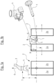
- valve bag filling device which is not shown in detail in the figures, is one which corresponds in its basic structure to the Greif-Velox "VELOVAC" machine, i.e. a valve bag vacuum filling device in which the powdery filling material to be filled is conveyed from a storage container via a conveyor line to a filling nozzle 1 which protrudes from the front of the machine and is intended to receive a valve hose of a valve bag.
- VELOVAC Greif-Velox "VELOVAC” machine
- the filling process takes place within a vacuum chamber 2 which consists of two chamber halves 2a and 2b which Purpose of the filling process, as in Figure 1a is shown, are moved together to form a closed vacuum chamber 2, in which the filling nozzle 1 is located with its free end with a valve hose of a valve bag sitting on it, which is to be filled with powdery filling material.
- the construction and function of the machines are basically as shown in DE 20 2018 006 418 U1 known, to which reference is made here.
- the valve bag filling device described here differs from the previously known one in that a suction device is provided for sucking out excess filling material, of which Figure 1a a suction hose 3 with a housing 4 at the end, which has a suction opening 5, is shown.
- the suction hose 3 is connected to a suction pump with the inclusion of a filter.
- the suction housing 4, which includes the suction opening 5, can be moved up and down in the vertical direction 6 in relation to the filling nozzle 1 by means of a linear drive (not shown in detail here).
- the drive is electric or pneumatic.
- two end positions are provided, namely the one in Figure 1a shown position 7 away from the nozzle, in which the suction housing 4 is arranged at a distance above the vacuum chamber 2, as well as the Figure 1b shown position 8 near the nozzle, in which the housing 4 is arranged in the immediate vicinity of the filling nozzle 1, namely at a small distance above it.
- This position 8 near the nozzle can only be reached when the halves 2a and 2b of the vacuum chamber 2 are opened, ie moved apart after the filling process has been completed.
- the suction housing 4 is expediently lowered into the position 8 near the nozzle only after the filled valve bag has been removed from the filling nozzle 1.
- the suction housing 4 In the position 7 away from the nozzle, the suction housing 4 has a distance 9 which is significantly greater than the distance 10 in the position near the nozzle.
- Position 8 near the nozzle is in the Figures 2, 3 and 5 This position 8 close to the nozzle serves to suck out excess filling material on the filling nozzle 1 after the filling process.
- the suction housing 4 has a suction nozzle 11, which has an upper cylindrical section 12 for connection to the suction hose 3.
- the cylindrical section 12 extends downwards into a widening section 13, which has a semicircular recess 14 at its lower end on one side of its lateral surface, which in the position 8 near the nozzle has an end section 15 of the filling nozzle 1 for forming a semi-annular gap 16 as part of the suction opening 5.
- the lower part 17 of the annular gap is formed by the edges of two housing sections 18 and 19, which in Figure 2 in a folded-down position, in which these housing sections 18 and 19 are arranged next to the suction nozzle 11. These housing sections 18 and 19 can be folded into the position shown in FIG.
- FIG. 1 by means of a mechanism 20 arranged on the rear side of the suction nozzle 11, which can be driven electromagnetically or pneumatically.
- Figure 3 shown closed position, in which the housing sections 18 and 19 continue the widening section 13 downwards on its straight sides and close the housing to form an annular suction gap consisting of the semi-annular upper gap 16 and the semi-annular lower gap 17.
- the air is extracted through the annular gap 16, 17 into the housing 4, which tapers upwards in the widening section 13 and connects to the suction hose 3 in the cylindrical section 12.
- blow nozzles 21 provided inside the area of the widening section 13, which are connected to a compressed air line and which generate a targeted, strong air flow directed at the filling nozzle section 15, which further increases the removal of particles adhering to the filling nozzle section 15.
- one or more pulse-like pressure surges are advantageously initially carried out by the blow nozzles 21 before or simultaneously with the suction through the housing 4.
- the suction device has a control device which, on the one hand, is provided with the drive for moving the housing 4 from the position 7 remote from the nozzle to the position 8 close to the nozzle and vice versa, as well as the drive for the mechanism 20 which moves the housing sections 18 and 19 from the position shown in Figure 2 and 4 shown folded position to the one in Figure 3 shown folded-in position and vice versa, in which the housing 4 is essentially closed and only has an annular suction gap 16, 17 formed around the filling nozzle 1.
- a control is provided which coordinates the movement of the drives with that of the rest of the machine. This control can be part of the machine control or also an external control, which is however expediently signal-connected to the machine control or at least recognizes the states relevant for the control.
- the control ensures that the suction housing 4 is only moved from the position 7 away from the nozzle to the position 8 near the nozzle when the vacuum chamber 2 is opened, i.e. the left half 2a and the right half 2b of the vacuum chamber 2 are moved apart and the filled valve bag is removed from the filling nozzle 1 and thus from the vacuum chamber 2 is removed.
- the control for actuating the mechanism 20 is subsequently to be activated so that the housing sections 18 and 19 pivot downwards to close the suction housing 4, i.e. are arranged under the suction nozzle 11, so that the annular gap 16, 17 is formed for suctioning the filling nozzle section 15.
- the suction is activated and if necessary the compressed air is applied through the blow nozzles 21 until the cleaning process is finished.
- a particle sensor can be provided in the exhaust air path, which detects this.
Landscapes
- Engineering & Computer Science (AREA)
- Mechanical Engineering (AREA)
- Chemical & Material Sciences (AREA)
- Dispersion Chemistry (AREA)
- Basic Packing Technique (AREA)
Description
- Die Erfindung betrifft eine Ventilsackabfüllvorrichtung zum Abfüllen von pulverförmigen Füllgut in einen Ventilsack.
- Derartige Ventilsackabfüllvorrichtungen zählen in zahlreichen Ausführungsvarianten zum Stand der Technik. Sie weisen typischerweise einen Füllstutzten auf, der zum Einführen in einen Ventilschlauch eines abzufüllenden Ventilsackes vorgesehen ist und eine Fördervorrichtung, mit der das abzufüllende Füllgut aus einem Vorratsbehältnis durch den Füllstutzen in einen mit dem Ventilschlauch auf dem Füllstutzen sitzenden Ventilsack fördert. Dabei zählt es zum Stand der Technik, eine Absaugvorrichtung zum Absaugen von überschüssigen Füllgut vorzusehen, welche eine Absaugöffnung aufweist, die mit Abstand zum Füllstutzen angeordnet ist. Eine solche Absaugvorrichtung ist zum Absaugen der beim Füllvorgang in die Umgebungsluft gelangenden Füllgutes vorgesehen.
- Eine Ventilsackabfüllvorrichtung ist beispielsweise aus
DE 20 2018 006 418 U1 bekannt. Bei dieser Ventilsackabfüllvorrichtung handelt es sich um eine Vakuumabfüllvorrichtung, bei welcher der Ventilsack innerhalb einer Vakuumkammer angeordnet wird und der Füllvorgang im Wesentlichen durch Unterdruck in der Kammer erfolgt. Hierüber gelangt nicht nur die mit dem Füllgut mitgeführtes Gas, insbesondere Luft in die Absaugvorrichtung, sondern auch überschüssiges Füllgut, wenn der Ventilsack defekt ist oder nicht dicht auf dem Füllstutzen angeordnet ist. Mittels eines Staubsensors wird dieses detektiert und der Füllvorgang abgebrochen. -
DE 38 34 810 A1 offenbart eine Vorrichtung zum Füllen von Ventilsäcken mit einem in den Ventilsack eingreifenden Füllstutzen, wobei der Ventilsack durch Überdruck mit Hilfe einer Füllturbine befüllt wird. Oberhalb des in den Ventil-sack eingreifenden Füllstutzens ist ein Absaugstutzen angeordnet, über welchen Partikel abgesaugt werden können, wenn der Ventilsack vom Füllstutzen abgezogen wird. - Der Erfindung liegt die Aufgabe zugrunde, eine Ventilsackabfüllvorrichtung so auszubilden, dass mit dieser überschüssiges Füllgut beim Abfüllen zuverlässiger entfernt werden kann. Dies ist insbesondere bei Füllgut, wie Grafitstaub, Farbpigmenten und dergleichen erforderlich, bei dem Füllgutreste den nachfolgenden Füllvorgang oder das Äußere eines Ventilsacks negativ beeinflussen würden.
- Diese Aufgabe wird durch eine Ventilsackabfüllvorrichtung mit dem in Anspruch 1 angegebenen Merkmalen gelöst, vorteilhafte Ausgestaltungen der Erfindung sind in den Unteransprüchen, der nachfolgenden Beschreibung und der Zeichnung angegeben.
- Die erfindungsgemäße Ventilsackabfüllvorrichtung ist zum Abfüllen von pulverförmigen Füllgut in einen Ventilsack bestimmt und ausgebildet. Sie weist einen Füllstutzen auf, der zum Einführen in einen Ventilschlauch eines abzufüllenden Ventilsackes vorgesehen ist, sowie eine Fördervorrichtung, mit der das abzufüllende Füllgut von einem Vorratsbehältnis durch den Füllstutzen hindurch in einen mit dem Ventilschlauch auf dem Füllstutzen sitzenden Ventilsack erfolgt. Es ist eine Absaugvorrichtung zum Absaugen von überschüssigem Füllgut vorgesehen, welcher eine mit Abstand zum Füllstutzen angeordnete Absaugöffnung aufweist. Gemäß der Erfindung ist eine Steuervorrichtung vorgesehen, mit der die Absaugöffnung in Bezug auf den Füllstutzen verfahrbar ist.
- Grundgedanke der erfindungsgemäßen Lösung ist es somit, die Absaugöffnung der Absaugvorrichtung mittels einer Steuervorrichtung verfahrbar anzuordnen, sodass die Absagöffnung in Bezug auf den Füllstutzen verfahrbar ist. Diese Verfahrbarkeit hat den Vorteil, dass einerseits ein ausreichend größer Abstand der Ansaugöffnung zum Füllstutzen angefahren werden kann, um das Bestücken der Vorrichtung mit dem Ventilsatz, den Füllvorgang und die Entnahme des gefüllten Ventilsatzes aus der Vorrichtung nicht zu behindern und andererseits die Absaugöffnung so nah an Füllstutzen verfahren werden kann, dass dort befindliches überschüssiges Füllgut, welches typischerweise nach Abschluss des Füllvorgangs und Entnahme des Ventilsacks auf dem Füllstutzen verbleibt, zuverlässig abgesaugt werden kann. Die erfindungsgemäße Ausgestaltung der Ventilsackabfüllvorrichtung ist nicht beschränkt auf solche Vorrichtungen, die mittels einer Vakuumkammer befüllen, sondern kann auch für Ventilsackabfüllvorrichtungen mit Druckbefüllung oder kombinierter Saugdruckbefüllung Anwendung finden.
- Die Steuervorrichtung weist einen Stellantrieb auf, mit dem die Absaugöffnung von einer stutzennahen in eine stutzenferne Stellung und umgekehrt verfahrbar ist. Ein solcher Stellantrieb kann beispielsweise elektrisch aber auch pneumatisch vorgesehen sein, zweckmäßigerweise an den bei der jeweiligen Ventilsackabfüllvorrichtung vorhandenen Antrieb angepasst. Wenn eine möglichst produktangepasste Verfahrbarkeit der Absaugöffnung gewünscht ist, kann der Stellantrieb einen Manipulator aufweisen, der beispielsweise die Absaugöffnung nicht nur an eine stutzennahe Stellung, sondern an eine Vielzahl von stutzennahen Stellen bewegen kann, beispielsweise die Absaugöffnung am Ende eines Absaugschlauches schraubenlinienförmig um das Ende des Füllstutzens zu führen, um diesen möglichst vollständig abzusaugen.
- Besonders vorteilhaft ist es, wenn die Steuervorrichtung eine Steuerung aufweist, mit der die gewünschte Stellung der Absaugöffnung steuerbar ist, wobei diese Steuerung vorteilhaft Teil der Maschinensteuerung der Ventilsackabfüllvorrichtung bildet oder zumindest mit dieser signalverbunden ist, um die Absaugung in automatisierte Füllvorgänge zu integrieren. Dabei ist die Steuerung vorteilhaft so ausgebildet, dass die stutzennahe Stellung erst nach Abnehmen des Ventilschlauchs vom Füllstutzen oder bereits nach Beendigung des Abfüllvorgangs angefahren wird. Im letzteren Fall kann insbesondere das beim Abziehen des Ventilschlauchs vom Füllstutzen freiwerdende Füllgut abgesaugt werden, im ersteren Fall ist primär eine Absaugung des Füllstutzens selbst vorgesehen.
- Besonders vorteilhaft einsetzbar ist die erfindungsgemäße Ausgestaltung bei einer Ventilsackvakuumabfüllvorrichtung mit einer Vakuumkammer, wobei die Absaugöffnung in der stutzenfernen Stellung außerhalb der Vakuumkammer und in der stutzennahen Stellung innerhalb, d.h. im Bereich der geöffneten Vakuumkammer angeordnet ist. Durch die Verfahrbarkeit der Absaugöffnung von einer stutzenfernen Stellung außerhalb der Vakuumkammer in eine stutzennahe Stellung innerhalb der geöffneten Vakuumkammer kann die Absaugvorrichtung auch an vorhandenen Ventilsackvakuumabfüllvorrichtungen nachgeröstet werden, da die Ventilkammer während des eigentlichen Absaugvorgangs von der Absaugvorrichtung unbeeinflusst ist, jedoch nach Öffnen der Ventilkammer, insbesondere nach Entfernen des Ventilsacks aus der Ventilkammer, hinsichtlich etwaiger Füllgutteile auf dem Füllstutzen abgesaugt werden kann. Typischerweise besteht die Vakuumkammer aus zwei Kammerhälften, in deren Mitte sich der Füllstutzen befindet, die zum Aufstecken des Ventilsacks und zum Abnehmen des befüllten Ventilsacks auseinandergefahren werden. In dieser auseinandergefahrenen Stellung wird vorteilhaft die Absaugöffnung in die stutzennahe Stellung in die geöffnete Vakuumkammer verfahren, um mit der Absaugöffnung möglichst nah an den Füllstutzten heranzukommen und so eine möglichst vollständige Absaugung des dort ggf. befindlichen überschüssigen Füllguts zu ermöglichen.
- Da überschüssiges Füllgut beim Entfernen des Ventilsacks vom Füllstutzen nicht nur auf der Oberseite des Füllstutzens aufliegen, sondern auch an beliebiger Stelle anhaften kann, ist es vorteilhaft, die Absaugung möglichst vollumfänglich durchzuführen. Hierzu ist gemäß der Erfindung die Absaugöffnung in ihrer stutzennahen Stellung ringförmig ausgebildet, sodass sie sich um einen Abschnitt des Füllstutzens erstrecken kann und diesen vollumfänglich absaugen kann.
- Vorteilhaft kann gemäß einer Weiterbildung der Erfindung die Absaugvorrichtung nicht nur mittels Unterdruck arbeiten, sondern mit Blasdüsen ausgestattet sein, die mit einer druckgasführenden Leitung verbunden sind. Derartige Blasdüsen sind vorteilhaft vor der Absaugöffnung innerhalb der Absaugleitung angeordnet und zwar so, dass ein möglichst gerichteter Luftstrom auf den Füllstutzen erfolgt, sodass das dort anhaftendes Füllgut durch den Luftstrom gelöst und nachfolgend durch die Absaugöffnung in die Absaugleitung abgesaugt wird.
- Um eine vollumfängliche Absaugung des Füllstutzens zu erreichen, kann eine ringförmige Absaugöffnung, z.B. mittels eines Manipulators längst des Füllstutzens, diesen umgebend geführt werden. Konstruktiv und steuerungstechnisch wesentlich einfacher ist es allerdings, wenn, was gemäß der Erfindung vorteilhaft vorgesehen sein kann, zwar eine ringförmige Absaugöffnung durch ein zum Füllstutzen hin offenes ringförmiges Gehäuse gebildet wird, welches zumindest ein abklappbares Gehäuseteil aufweist, welches es ermöglicht, dieses Gehäuse bei abgeklapptem Gehäuseteil radial über den Füllstutzen zu führen und nachfolgend durch Anklappen dieses Gehäuseteils eine den Füllstutzen ringförmig umgebende Absaugöffnung zu bilden. Vorzugsweise sind gemäß einer Weiterbildung der Erfindung zwei abklappbare Gehäuseteile vorgesehen, welche z.B. in ihrer abgeklappten Stellung den unteren, sich um etwa 180 Grad erstreckenden ringförmigen Gehäuseteil derart anordnen, dass dieser radial zum Füllstutzen z.B. nach oben zum Überführen von der stutzenfernen in die stutzennahe Stellung und umgekehrt verfahrbar ist.
- Eine konstruktiv einfache aber zugleich wirksame Ausgestaltung der Absaugleitung weist gemäß einer Weiterbildung der Erfindung einen endseitig angeordneten Absaugstutzen auf, der die obere Hälfte eines zum Füllstutzen hin offenen ringförmigen Gehäuses bildet, wobei die untere Hälfte dieses Gehäuses durch zwei untere Gehäuseabschnitte gebildet ist, die in geöffneter Stellung neben und in geschlossener Stellung unter dem Absaugstutzen angeordnet sind. Dabei ist die geöffnete Stellung, in welcher die Gehäuseabschnitte neben dem Absaugstutzen angeordnet sind, vorgesehen, um von der stutzenfernen in die stutzennahe Stellung zu verfahren, so weit bis die obere Gehäusehälfte des ringförmigen Gehäuses einen oberen Abschnitt des Füllstutzens umgibt. In dieser Stellung können dann vorteilhaft die unteren Gehäuseabschnitte angeklappt werden, um so eine den Füllstutzen ringförmig umgebener Absaugöffnung zu bilden. Die Absaugung erfolgt also in geschlossener Stellung, wohingegen die geöffnete Stellung zum Verfahren vorgesehen ist. Vorteilhaft ist bei dieser Ausgestaltung eine Steuerung vorgesehen, welche die unteren Gehäuseabschnitte nach Erreichen der füllstutzennahen Stellung unter Einschluss des Füllstutzens unter den Absaugstutzen verfährt und nach dem Absaugen diese wieder in die geöffnete Stellung zurückverfährt, sodass in die füllstutzenferne Stellung verfahren werden kann. Vorteilhaft ist die Steuerung automatisiert und in die Maschinesteuerung integriert oder zumindest mit dieser signalverbunden.
- Die Erfindung ist nachfolgend anhand eines Ausführungsbeispiels näher erläutert. Es zeigen:
- Figur 1
- in stark vereinfachter schematischer Darstellung, die Ausgestaltung und Anordnung einer Absaugöffnung der Absaugvorrichtung einer Ventilsackvakuumabfüllvorrichtung in einer füllstutzenfernen Stellung (
Figur 1a ) und in einer füllstutzennahen Stellung (Figur 1b ), - Figur 2
- in perspektivischer Ansicht einen über den Füllstutzen gefahrenen Absaugstutzen mit geöffneten unteren Gehäuseabschnitten,
- Figur 3
- den Absaugstutzen gemäß
Figur 2 in geschlossener Stellung der Gehäuseabschnitte, - Figur 4
- den Absaugstutzen gemäß
Figur 2 in geöffneter Stellung von der anderen Seite, und - Figur 5
- eine Ausführungsvariante im Teilschnitt der Darstellung nach
Figur 2 . - Bei der anhand der Figuren nicht im Einzelnen dargestellten Ventilsackabfüllvorrichtung handelt es sich um eine solche, wie sie in ihrem grundsätzlichen Aufbau der Maschine Greif-Velox "VELOVAC" entspricht, also eine Ventilsackvakuumabfüllvorrichtung, bei der das abzufüllende pulvrige Füllgut aus einem Vorratsbehälter über eine Förderleitung zu einem Füllstutzen 1 gefördert wird, der an der Vorderseite der Maschine vorsteht und zur Aufnahme eines Ventilschlauches eines Ventilsacks vorgesehen ist. Der Füllvorgang erfolgt innerhalb einer Vakuumkammer 2, die aus zwei Kammerhälften 2a und 2b besteht, welche zum Zwecke des Füllvorgangs, wie in
Figur 1a dargestellt ist, zu einer geschlossenen Vakuumkammer 2 zusammengefahren sind, in der sich der Füllstutzen 1 mit seinem freien Ende mit einem darauf sitzenden Ventilschlauch eines Ventilsacks befindet, der mit pulverförmigem Füllgut abzufüllen ist. Aufbau und Funktion der Maschinen sind grundsätzlich so, wie ausDE 20 2018 006 418 U1 bekannt, auf die insoweit hier verwiesen wird. - Die hier beschriebene Ventilsackabfüllvorrichtung unterscheidet sich von der vorbekannten dadurch, dass eine Absaugvorrichtung zum Absaugen von überschüssigem Füllgut vorgesehen ist, von der in
Figur 1a ein Absaugschlauch 3 mit einem endseitigen Gehäuse 4, welches eine Absaugöffnung 5 aufweist, dargestellt ist. Der Absaugschlauch 3 schließt unter Eingliederung eines Filters an einer Absaugpumpe an. Das Absauggehäuse 4, welches die Absaugöffnung 5 umfasst, kann mittels eines hier nicht im Einzelnen dargestellten Linearantriebs in vertikaler Richtung 6 in Bezug auf den Füllstutzen 1 nach oben und nach unten gefahren werden. Der Antrieb ist elektrisch oder pneumatisch. Im Ausführungsbeispiel sind zwei Endstellungen vorgesehen, nämlich die inFigur 1a dargestellte stutzenferne Stellung 7, in welcher das Absauggehäuse 4 mit Abstand über der Vakuumkammer 2 angeordnet ist, sowie die inFigur 1b dargestellte stutzennahe Stellung 8, in welcher das Gehäuse 4 in unmittelbarer Nähe des Füllstutzens 1, nämlich mit geringem Abstand darüber angeordnet ist. Diese stutzennahe Stellung 8 kann nur angefahren werden, wenn die Hälften 2a und 2b der Vakuumkammer 2 geöffnet, d.h. nach Abschluss des Füllvorgangs auseinandergefahren sind, zweckmäßigerweise erfolgt das Absenken des Absauggehäuses 4 in die stutzennahe Stellung 8 erst, nachdem der befüllte Ventilsack vom Füllstutzen 1 entfernt worden ist. - In der stutzenfernen Stellung 7 weist das Absauggehäuse 4 einen Abstand 9 auf, der deutlich größer ist, als der Abstand 10 in der stutzennahen Stellung 8. Die stutzennahe Stellung 8 ist in den
Figuren 2, 3 und5 dargestellt. Diese stutzennahe Stellung 8 dient zum Absaugen von auf dem Füllstutzen 1 befindlichem überschüssigem Füllgut nach dem Füllvorgang. - Das Absauggehäuse 4 weist ein Absaugstutzen 11 auf, der einen oberen zylindrischen Abschnitt 12 zum Anschluss an den Ansaugschlauch 3 aufweist. Der zylindrische Abschnitt 12 geht nach unten in einen aufweitenden Abschnitt 13 über, der an seinem unteren Ende an einer Seite seiner Mantelfläche eine halbkreisförmige Ausnehmung 14 aufweist, die in der stutzennahen Stellung 8 einen endseitigen Abschnitt 15 des Füllstutzens 1 zur Ausbildung eines halbringförmigen Spaltes 16 als Teil der Absaugöffnung 5 aufweist. Der untere Teil 17 des ringförmigen Spaltes wird durch die Ränder von zwei Gehäuseabschnitten 18 und 19 gebildet, welche in
Figur 2 in einer abgeklappten Position dargestellt sind, in welcher diese Gehäuseabschnitte 18 und 19 neben dem Absaugstutzen 11 angeordnet sind. Diese Gehäuseabschnitte 18 und 19 können mittels einer rückseitig am Absaugstutzen 11 angeordneten Mechanik 20, die elektromagnetisch oder pneumatisch angetrieben sein kann, in die inFigur 3 dargestellte geschlossene Position geschwenkt werden, in welcher die Gehäuseabschnitte 18 und 19 den aufweitenden Abschnitt 13 an seinen geraden Seiten nach unten hin fortsetzen und das Gehäuse unter Bildung eines aus dem halbringförmigen oberen Spalt 16 und dem halbringförmigen unteren Spalt 17 bestehenden ringförmigen Absaugspalt schließen. In dieser geschlossenen Stellung (Figur 3 ) erfolgt die Absaugung der Luft durch den ringförmigen Spalt 16, 17, in das Gehäuse 4, das sich im aufweitenden Abschnitt 13 nach oben verjüngt und im zylindrischen Abschnitt 12 an den Absaugschlauch 3 anschließt. Da der Querschnitt des Ringspaltes 16, 17 deutlich kleiner als der übrige Querschnitt des Gehäuses 4, insbesondere der des Absaugschlauches 3 ist, erfolgt eine Beschleunigung der in diesem Bereich angesaugten Luft und damit eine effektive Mitnahme von am Füllstutzen 1 anhaftenden pulvrigen Füllgut vom Füllvorgang. - Dieser Reinigungseffekt kann durch eine Anordnung von im Bereich des aufweitenden Abschnitts 13 innen vorgesehenen Blasdüsen 21 unterstützt werden, welche an eine druckluftführende Leitung angeschlossen sind und die einen auf den Füllstutzenabschnitt 15 gerichteten gezielten starken Luftstrom erzeugen, welcher die Abfuhr von am Füllstutzenabschnitt 15 anhaftenden Partikeln noch verstärken. Dabei erfolgen vorteilhaft zunächst ein oder mehrere pulsartige Druckstöße durch die Blasdüsen 21 vor oder gleichzeitig mit der Absaugung durch das Gehäuse 4.
- Die Absaugvorrichtung, wie sie vorstehend beschrieben ist, weist eine Steuervorrichtung auf, die zum einen den Antrieb zum Verfahren des Gehäuses 4 aus den stutzenfernen Stellung 7 in die stutzennahen Stellung 8 und umgekehrt vorgesehen ist, sowie den Antrieb für die Mechanik 20, welche die Gehäuseabschnitte 18 und 19 aus der in
Figur 2 und4 dargestellten abgeklappten Stellung in die inFigur 3 dargestellte eingeklappte Stellung und umgekehrt bewegen, in welcher das Gehäuse 4 im Wesentlichen geschlossen ist und lediglich einen um den Füllstutzen 1 gebildeten ringförmigen Absaugspalt 16, 17 aufweist. Weiterhin ist eine Steuerung vorgesehen, welche die Bewegung der Antriebe mit der der übrigen Maschine koordiniert. Diese Steuerung kann Teil der Maschinensteuerung sein oder auch eine externe Steuerung, die jedoch zweckmäßigerweise mit der Maschinesteuerung signalverbunden ist oder zumindest die für die Steuerung relevanten Zustände erkennt. Die Steuerung sorgt dafür, dass das Absauggehäuse 4 aus der stutzenfernen Stellung 7 in die stutzennahe Stellung 8 erst dann verfahren wird, wenn die Vakuumkammer 2 geöffnet, d.h. die linke Hälfte 2a und die rechte Hälfte 2b der Vakuumkammer 2 auseinandergefahren sind und der gefüllte Ventilsack vom Füllstutzen 1 und somit aus der Vakuumkammer 2 entfernt ist. Wenn dann die Steuerung den Antrieb zum Verfahren des Absauggehäuses 4 in die stutzennahe Stellung 8 gesteuert hat, ist nachfolgend die Ansteuerung zur Betätigung der Mechanik 20 zu aktivieren, sodass die Gehäuseabschnitte 18 und 19 zum Schlie-ßen des Absauggehäuses 4 nach unten schwenken, also unter dem Absaugstutzen 11 angeordnet sind, sodass der Ringspalt 16, 17 zum Absaugen des Füllstutzenabschnitts 15 gebildet ist. - Nach Erreichen dieser Stellung spätestens wird die Absaugung aktiviert und ggf. die Druckluftbeaufschlagung durch die Blasdüsen 21 bis der Reinigungsvorgang beendet ist. Hierfür kann ein Partikelsensor im Abluftweg vorgesehen sein, der dieses detektiert. Nach Abschluss der Absaugung wird der Antrieb für die Mechanik 20 zum Öffnen der Gehäuseabschnitte 18 und 19 in die in
Figur 2 und4 dargestellte Stellung aktiviert, wonach der Antrieb zum Hochfahren des Absauggehäuses 4 in die stutzenferne Stellung 7 aktiviert wird. Danach ist die Maschine zur Beschickung mit einem leeren Ventilsack und nachfolgenden Füllvorgang wieder bereit. -
- 1
- Füllstutzen
- 2
- Vakuumkammer
- 2a
- linke Hälfte der Vakuumkammer
- 2b
- rechte Hälfte der Vakuumkammer
- 3
- Absaugschlauch
- 4
- Absauggehäuse
- 5
- Absaugöffnung
- 6
- Verfahrrichtung
- 7
- stutzenferne Stellung
- 8
- stutzennahe Stellung
- 9
- Abstand zum Füllstutzen in Stellung 7
- 10
- Abstand zum Füllstutzen in Stellung 8
- 11
- Absaugstutzen
- 12
- zylindrischer Abschnitt
- 13
- konischer Abschnitt
- 14
- halbkreisförmiger Ausnehmung
- 15
- endseitiger Abschnitt
- 16
- halbkreisförmiger Spalt oben
- 17
- halbkreisförmiger Spalt unten
- 18
- Gehäuseabschnitt
- 19
- Gehäuseabschnitt
- 20
- Mechanik
- 21
- Blasdüsen
Claims (8)
- Ventilsackabfüllvorrichtung zum Abfüllen von pulverförmigen Füllgut in einen Ventilsack, mit einem Füllstutzen (1), der zum Einführen in einen Ventilschlauch eines abzufüllenden Ventilsackes vorgesehen ist, mit einer Fördervorrichtung zum Fördern des abzufüllenden Füllguts von einem Vorratsbehältnis durch den Füllstutzen (1) in einen mit dem Ventilschlauch auf dem Füllstutzen (1) sitzenden Ventilsack und mit einer Absaugvorrichtung (3, 4) zum Absaugen von überschüssigem Füllgut mit einer Absaugöffnung (5), die mit Abstand (9, 10) zum Füllstutzen (1) angeordnet ist,
wobeieine Steuervorrichtung vorgesehen ist, mit der die Absaugöffnung (5) in Bezug auf den Füllstutzen (1) verfahrbar ist,dadurch gekennzeichnet, dassdie Steuervorrichtung einen Stellantrieb (6) aufweist, mit dem die Absaugöffnung (5) von einer stutzennahen Stellung (8) in eine stutzenferne Stellung (7) und umgekehrt verfahrbar ist, und dass sich die Absaugöffnung (5) in ihrer stutzennahen Stellung (8) ringförmig um einen Abschnitt (15) des Füllstutzens (1) erstreckt. - Ventilsackabfüllvorrichtung nach Anspruch 1, dadurch gekennzeichnet, dass der Stellantrieb einen Manipulator aufweist.
- Ventilsackabfüllvorrichtung nach einem der vorhergehenden Ansprüche, dadurch gekennzeichnet, dass die Steuervorrichtung eine Steuerung aufweist, die Teil der Maschinensteuerung der Ventilsackabfüllvorrichtung bildet oder mit dieser signalverbunden ist, derart, dass die stutzennahe Stellung (8) erst nach Abnehmen des Ventilschlauchs vom Füllstutzen (1) oder nach Beendigung des Abfüllvorgangs angefahren wird.
- Ventilsackabfüllvorrichtung nach einem der vorhergehenden Ansprüche, dadurch gekennzeichnet, dass die Ventilsackabfüllvorrichtung eine Ventilsackvakuumabfüllvorrichtung mit einer Vakuumkammer (2) ist, und dass die Absaugöffnung (5) in der stutzenfernen Stellung (7) außerhalb der Vakuumkammer (2) und in der stutzennahen Stellung (8) innerhalb der geöffneten Vakuumkammer (2) angeordnet ist.
- Ventilsackabfüllvorrichtung nach einem der vorhergehenden Ansprüche, dadurch gekennzeichnet, dass die Absaugöffnung (5) das Ende einer Absaugleitung (3, 4) bildet und dass vor der Absaugöffnung (5) innerhalb der Absaugleitung in Richtung zum Füllstutzen (1) gerichtete Blasdüsen (21) einer Druckgas führenden Leitung angeordnet sind.
- Ventilsackabfüllvorrichtung nach einem der vorhergehenden Ansprüche, dadurch gekennzeichnet, dass die ringförmige Absaugöffnung (16, 17) durch ein zum Füllstutzen (1) hin offenes ringförmiges Gehäuse (4) begrenzt wird, dass vorzugsweise zwei abklappbare Gehäuseteile (18, 19) aufweist.
- Ventilsackabfüllvorrichtung nach einem der vorhergehenden Ansprüche, dadurch gekennzeichnet, dass die Absaugleitung (3, 4) endseitig einen Absaugstutzen (11) aufweist, der die obere Hälfte des zum Füllstutzen hin offenen ringförmigen Gehäuses (4) bildet, wobei die untere Hälfte dieses Gehäuses (4) durch zwei untere Gehäuseabschnitte (18, 19) gebildet ist, die in geöffneter Stellung neben und in geschlossener Stellung unter dem Absaugstutzen (11) angeordnet sind.
- Ventilsackabfüllvorrichtung nach einem der vorhergehenden Ansprüche, dadurch gekennzeichnet, dass eine Steuerung vorgesehen ist, welche die unteren Gehäuseabschnitte (18, 19) nach Erreichen der füllstutzennahen Stellung (8) unter Einschluss des Füllstutzens (1) unter den Absaugstutzen (11) und nach erfolgter Absaugung zurückverfährt.
Priority Applications (2)
| Application Number | Priority Date | Filing Date | Title |
|---|---|---|---|
| EP22180479.2A EP4296174B1 (de) | 2022-06-22 | 2022-06-22 | Ventilsackabfüllvorrichtung |
| US18/338,420 US12466589B2 (en) | 2022-06-22 | 2023-06-21 | Valve bag filling device |
Applications Claiming Priority (1)
| Application Number | Priority Date | Filing Date | Title |
|---|---|---|---|
| EP22180479.2A EP4296174B1 (de) | 2022-06-22 | 2022-06-22 | Ventilsackabfüllvorrichtung |
Publications (3)
| Publication Number | Publication Date |
|---|---|
| EP4296174A1 EP4296174A1 (de) | 2023-12-27 |
| EP4296174B1 true EP4296174B1 (de) | 2024-10-30 |
| EP4296174C0 EP4296174C0 (de) | 2024-10-30 |
Family
ID=82214296
Family Applications (1)
| Application Number | Title | Priority Date | Filing Date |
|---|---|---|---|
| EP22180479.2A Active EP4296174B1 (de) | 2022-06-22 | 2022-06-22 | Ventilsackabfüllvorrichtung |
Country Status (2)
| Country | Link |
|---|---|
| US (1) | US12466589B2 (de) |
| EP (1) | EP4296174B1 (de) |
Family Cites Families (7)
| Publication number | Priority date | Publication date | Assignee | Title |
|---|---|---|---|---|
| DE584956C (de) * | 1929-04-26 | 1933-10-04 | Johannes Gravenholdt Dipl Ing | Sackfuellmaschine mit Staubabsaugung |
| US4219054A (en) * | 1978-06-07 | 1980-08-26 | Carter Industries | Method and apparatus for filling valve bags |
| US4576210A (en) * | 1982-09-28 | 1986-03-18 | Champion International Corporation | Duck bill filler nozzle |
| US4567922A (en) * | 1982-09-28 | 1986-02-04 | Champion International Corporation | Method of filling valve bags |
| DE3834810A1 (de) * | 1988-10-13 | 1990-04-19 | Haver & Boecker | Vorrichtung zum fuellen von ventilsaecken |
| DE102006021850A1 (de) * | 2006-05-09 | 2007-11-15 | Haver & Boecker Ohg | Füllmaschine für offene, schweißbare Säcke |
| DE202018006418U1 (de) | 2018-06-15 | 2020-05-06 | Greif-Velox Maschinenfabrik Gmbh | Ventilsackabfüllvorrichtung |
-
2022
- 2022-06-22 EP EP22180479.2A patent/EP4296174B1/de active Active
-
2023
- 2023-06-21 US US18/338,420 patent/US12466589B2/en active Active
Also Published As
| Publication number | Publication date |
|---|---|
| US20230415930A1 (en) | 2023-12-28 |
| EP4296174C0 (de) | 2024-10-30 |
| EP4296174A1 (de) | 2023-12-27 |
| US12466589B2 (en) | 2025-11-11 |
Similar Documents
| Publication | Publication Date | Title |
|---|---|---|
| EP2554501B1 (de) | Verfahren zum Transport von Lebensmittelscheiben | |
| EP0142763A1 (de) | Sackschneide- und Entleerungsgerät mit angeschlossenem Sammelentstaubungsfilter | |
| DE3421885A1 (de) | Geraet zum reinigen der gasduese eines schweissbrenners | |
| EP1074344A2 (de) | Vorrichtung zu Reinigung von Vulkanisationsformen | |
| DE19928734B4 (de) | Unterdruckhandhabungseinrichtung | |
| DE19520409C1 (de) | Vorrichtung zum Kuppeln von Behältnissen mit Blas- und Absaugeinrichtung | |
| DE3900664A1 (de) | Verfahren und vorrichtung zum reinigen des rohmaterial-beschickungsbehaelters einer verarbeitungsmaschine | |
| EP3552714B1 (de) | Pulverförderer zum fördern von beschichtungspulver, verfahren zum herstellen des pulverförderers und pulverzentrum mit dem pulverförderer zum versorgen einer pulverbeschichtungsanlage | |
| EP4296174B1 (de) | Ventilsackabfüllvorrichtung | |
| EP3017933A2 (de) | Vorrichtung zum laserauftragsschweissen zur additiven fertigung dreidimensionaler objekte | |
| EP3552713B1 (de) | Pulverzentrum zum versorgen einer pulverbeschichtungsanlage mit beschichtungspulver und verfahren zum reinigen des pulverzentrums | |
| EP4212440A1 (de) | Vorrichtung und verfahren zum anheben von packmittel | |
| DE19506538A1 (de) | Pulver-Entnahmevorrichtung | |
| EP1318961B1 (de) | Einrichtung zum einfüllen eines schüttgutes in einen behälter und verfahren zur anwendung | |
| WO2021197543A1 (de) | Vorrichtung zur reinigung von im pulverbett gedruckten dreidimensionalen bauteilen von anhaftenden pulverpartikeln | |
| DE69506176T2 (de) | Strahlanlage für Maskenformmaschine | |
| DE19944057A1 (de) | Verfahren und Vorrichtung zur Abreinigung von Schlauchfiltern | |
| DE10023921A1 (de) | Vorrichtung zum Halten eines flächigen Gegenstandes durch Ansaugen desselben | |
| EP0900164A1 (de) | Verfahren und vorrichtung zur vermeidung von produktestaub- oder produktegasaustritt bei abfüllung mit feststoff- oder flüssigkeitsdosiersystemen | |
| DE4234538C1 (de) | Vorrichtung zum Absaugen von insbesondere staubhaltigen Gasen | |
| CH692143A5 (de) | Verfahren und Vorrichtung zur Vermeidung von Produktestaub- oder Produktegasaustritt bei Abfüllung mit Feststoff- oder Flüssigkeitsdosiersystemen. | |
| DE202019104874U1 (de) | Mischmaschine | |
| EP0661213A1 (de) | Etiketten-Einleger und Verfahren zum Betrieb desselben | |
| DE102019123666B3 (de) | Mischmaschine | |
| DE3834810C2 (de) |
Legal Events
| Date | Code | Title | Description |
|---|---|---|---|
| PUAI | Public reference made under article 153(3) epc to a published international application that has entered the european phase |
Free format text: ORIGINAL CODE: 0009012 |
|
| STAA | Information on the status of an ep patent application or granted ep patent |
Free format text: STATUS: REQUEST FOR EXAMINATION WAS MADE |
|
| 17P | Request for examination filed |
Effective date: 20230818 |
|
| AK | Designated contracting states |
Kind code of ref document: A1 Designated state(s): AL AT BE BG CH CY CZ DE DK EE ES FI FR GB GR HR HU IE IS IT LI LT LU LV MC MK MT NL NO PL PT RO RS SE SI SK SM TR |
|
| GRAP | Despatch of communication of intention to grant a patent |
Free format text: ORIGINAL CODE: EPIDOSNIGR1 |
|
| STAA | Information on the status of an ep patent application or granted ep patent |
Free format text: STATUS: GRANT OF PATENT IS INTENDED |
|
| GRAJ | Information related to disapproval of communication of intention to grant by the applicant or resumption of examination proceedings by the epo deleted |
Free format text: ORIGINAL CODE: EPIDOSDIGR1 |
|
| STAA | Information on the status of an ep patent application or granted ep patent |
Free format text: STATUS: REQUEST FOR EXAMINATION WAS MADE |
|
| GRAP | Despatch of communication of intention to grant a patent |
Free format text: ORIGINAL CODE: EPIDOSNIGR1 |
|
| STAA | Information on the status of an ep patent application or granted ep patent |
Free format text: STATUS: GRANT OF PATENT IS INTENDED |
|
| INTG | Intention to grant announced |
Effective date: 20240814 |
|
| GRAS | Grant fee paid |
Free format text: ORIGINAL CODE: EPIDOSNIGR3 |
|
| INTC | Intention to grant announced (deleted) | ||
| GRAA | (expected) grant |
Free format text: ORIGINAL CODE: 0009210 |
|
| STAA | Information on the status of an ep patent application or granted ep patent |
Free format text: STATUS: THE PATENT HAS BEEN GRANTED |
|
| INTG | Intention to grant announced |
Effective date: 20240916 |
|
| AK | Designated contracting states |
Kind code of ref document: B1 Designated state(s): AL AT BE BG CH CY CZ DE DK EE ES FI FR GB GR HR HU IE IS IT LI LT LU LV MC MK MT NL NO PL PT RO RS SE SI SK SM TR |
|
| REG | Reference to a national code |
Ref country code: GB Ref legal event code: FG4D Free format text: NOT ENGLISH |
|
| REG | Reference to a national code |
Ref country code: CH Ref legal event code: EP |
|
| REG | Reference to a national code |
Ref country code: DE Ref legal event code: R096 Ref document number: 502022002003 Country of ref document: DE |
|
| REG | Reference to a national code |
Ref country code: IE Ref legal event code: FG4D Free format text: LANGUAGE OF EP DOCUMENT: GERMAN |
|
| U01 | Request for unitary effect filed |
Effective date: 20241104 |
|
| U07 | Unitary effect registered |
Designated state(s): AT BE BG DE DK EE FI FR IT LT LU LV MT NL PT RO SE SI Effective date: 20241114 |
|
| PG25 | Lapsed in a contracting state [announced via postgrant information from national office to epo] |
Ref country code: IS Free format text: LAPSE BECAUSE OF FAILURE TO SUBMIT A TRANSLATION OF THE DESCRIPTION OR TO PAY THE FEE WITHIN THE PRESCRIBED TIME-LIMIT Effective date: 20250228 Ref country code: HR Free format text: LAPSE BECAUSE OF FAILURE TO SUBMIT A TRANSLATION OF THE DESCRIPTION OR TO PAY THE FEE WITHIN THE PRESCRIBED TIME-LIMIT Effective date: 20241030 |
|
| PG25 | Lapsed in a contracting state [announced via postgrant information from national office to epo] |
Ref country code: ES Free format text: LAPSE BECAUSE OF FAILURE TO SUBMIT A TRANSLATION OF THE DESCRIPTION OR TO PAY THE FEE WITHIN THE PRESCRIBED TIME-LIMIT Effective date: 20241030 |
|
| PG25 | Lapsed in a contracting state [announced via postgrant information from national office to epo] |
Ref country code: NO Free format text: LAPSE BECAUSE OF FAILURE TO SUBMIT A TRANSLATION OF THE DESCRIPTION OR TO PAY THE FEE WITHIN THE PRESCRIBED TIME-LIMIT Effective date: 20250130 |
|
| PG25 | Lapsed in a contracting state [announced via postgrant information from national office to epo] |
Ref country code: GR Free format text: LAPSE BECAUSE OF FAILURE TO SUBMIT A TRANSLATION OF THE DESCRIPTION OR TO PAY THE FEE WITHIN THE PRESCRIBED TIME-LIMIT Effective date: 20250131 |
|
| PG25 | Lapsed in a contracting state [announced via postgrant information from national office to epo] |
Ref country code: PL Free format text: LAPSE BECAUSE OF FAILURE TO SUBMIT A TRANSLATION OF THE DESCRIPTION OR TO PAY THE FEE WITHIN THE PRESCRIBED TIME-LIMIT Effective date: 20241030 |
|
| PG25 | Lapsed in a contracting state [announced via postgrant information from national office to epo] |
Ref country code: RS Free format text: LAPSE BECAUSE OF FAILURE TO SUBMIT A TRANSLATION OF THE DESCRIPTION OR TO PAY THE FEE WITHIN THE PRESCRIBED TIME-LIMIT Effective date: 20250130 |
|
| PG25 | Lapsed in a contracting state [announced via postgrant information from national office to epo] |
Ref country code: SM Free format text: LAPSE BECAUSE OF FAILURE TO SUBMIT A TRANSLATION OF THE DESCRIPTION OR TO PAY THE FEE WITHIN THE PRESCRIBED TIME-LIMIT Effective date: 20241030 |
|
| U20 | Renewal fee for the european patent with unitary effect paid |
Year of fee payment: 4 Effective date: 20250604 |
|
| PG25 | Lapsed in a contracting state [announced via postgrant information from national office to epo] |
Ref country code: SK Free format text: LAPSE BECAUSE OF FAILURE TO SUBMIT A TRANSLATION OF THE DESCRIPTION OR TO PAY THE FEE WITHIN THE PRESCRIBED TIME-LIMIT Effective date: 20241030 |
|
| PG25 | Lapsed in a contracting state [announced via postgrant information from national office to epo] |
Ref country code: CZ Free format text: LAPSE BECAUSE OF FAILURE TO SUBMIT A TRANSLATION OF THE DESCRIPTION OR TO PAY THE FEE WITHIN THE PRESCRIBED TIME-LIMIT Effective date: 20241030 |
|
| PLBI | Opposition filed |
Free format text: ORIGINAL CODE: 0009260 |
|
| 26 | Opposition filed |
Opponent name: IMERTECH SAS Effective date: 20250730 |
|
| PLBG | Opposition deemed not to have been filed |
Free format text: ORIGINAL CODE: 0009274 |
|
| REG | Reference to a national code |
Ref country code: CH Ref legal event code: L10 Free format text: ST27 STATUS EVENT CODE: U-0-0-L10-L00 (AS PROVIDED BY THE NATIONAL OFFICE) Effective date: 20251217 |
|
| 26D | Opposition deemed not to have been filed |
Opponent name: IMERTECH SAS Effective date: 20251208 |
|
| REG | Reference to a national code |
Ref country code: CH Ref legal event code: H13 Free format text: ST27 STATUS EVENT CODE: U-0-0-H10-H13 (AS PROVIDED BY THE NATIONAL OFFICE) Effective date: 20260127 |
|
| PG25 | Lapsed in a contracting state [announced via postgrant information from national office to epo] |
Ref country code: MC Free format text: LAPSE BECAUSE OF FAILURE TO SUBMIT A TRANSLATION OF THE DESCRIPTION OR TO PAY THE FEE WITHIN THE PRESCRIBED TIME-LIMIT Effective date: 20241030 |