EP4295050B1 - Pumpe mit elektronikgehäuse und kühlkörper - Google Patents
Pumpe mit elektronikgehäuse und kühlkörper Download PDFInfo
- Publication number
- EP4295050B1 EP4295050B1 EP22706841.8A EP22706841A EP4295050B1 EP 4295050 B1 EP4295050 B1 EP 4295050B1 EP 22706841 A EP22706841 A EP 22706841A EP 4295050 B1 EP4295050 B1 EP 4295050B1
- Authority
- EP
- European Patent Office
- Prior art keywords
- intermediate piece
- motor housing
- opening
- cooling body
- pump
- Prior art date
- Legal status (The legal status is an assumption and is not a legal conclusion. Google has not performed a legal analysis and makes no representation as to the accuracy of the status listed.)
- Active
Links
Images

Classifications
-
- F—MECHANICAL ENGINEERING; LIGHTING; HEATING; WEAPONS; BLASTING
- F04—POSITIVE - DISPLACEMENT MACHINES FOR LIQUIDS; PUMPS FOR LIQUIDS OR ELASTIC FLUIDS
- F04D—NON-POSITIVE-DISPLACEMENT PUMPS
- F04D13/00—Pumping installations or systems
- F04D13/02—Units comprising pumps and their driving means
- F04D13/06—Units comprising pumps and their driving means the pump being electrically driven
- F04D13/0686—Mechanical details of the pump control unit
-
- F—MECHANICAL ENGINEERING; LIGHTING; HEATING; WEAPONS; BLASTING
- F04—POSITIVE - DISPLACEMENT MACHINES FOR LIQUIDS; PUMPS FOR LIQUIDS OR ELASTIC FLUIDS
- F04D—NON-POSITIVE-DISPLACEMENT PUMPS
- F04D29/00—Details, component parts, or accessories
- F04D29/58—Cooling; Heating; Diminishing heat transfer
- F04D29/5813—Cooling the control unit
-
- F—MECHANICAL ENGINEERING; LIGHTING; HEATING; WEAPONS; BLASTING
- F04—POSITIVE - DISPLACEMENT MACHINES FOR LIQUIDS; PUMPS FOR LIQUIDS OR ELASTIC FLUIDS
- F04D—NON-POSITIVE-DISPLACEMENT PUMPS
- F04D29/00—Details, component parts, or accessories
- F04D29/58—Cooling; Heating; Diminishing heat transfer
- F04D29/586—Cooling; Heating; Diminishing heat transfer specially adapted for liquid pumps
- F04D29/5893—Cooling; Heating; Diminishing heat transfer specially adapted for liquid pumps heat insulation or conduction
Definitions
- the invention relates to a pump comprising a drive motor, at least one electronics housing and at least one heat sink for heat dissipation from the electronics housing, wherein an intermediate piece for thermal decoupling of the heat sink from the motor housing is introduced between the heat sink and the motor housing, and wherein the intermediate piece has at least one feedthrough opening for the passage of at least one component between the motor housing and the heat sink.
- Pumps consist of different components that generate waste heat independently of one another during pump operation.
- An electric motor is often used as the pump drive, the waste heat generated during operation of which is dissipated via the motor housing.
- Control electronics in particular a frequency converter, are provided for controlling/regulating the pumps or the electric motor, which is housed in a separate electronics housing.
- the electronics housing is installed on the motor housing in the sense of a compact pump structure, as disclosed in WO2013135465 A1 .
- both housings ie the motor and the electronics housing, must be thermally decoupled from each other.
- the latter is usually equipped with its own heat sink to optimize heat dissipation.
- an intermediate piece was used between the heat sink of the electronics housing and the motor housing to achieve the necessary thermal decoupling.
- the intermediate piece was, for example, a plastic part that separated the facing sides of the heat sink and the motor housing from each other.
- the intermediate piece, the electronics housing with heat sink and the motor housing must all have openings to provide feedthrough openings for the connecting cables.
- the entry of splash water through these feedthrough openings must be prevented, which is why these openings must be sealed from the environment using special measures.
- a sealing lip was sprayed directly into the area of the intermediate piece or a separate sealing element, such as an O-ring, was used.
- this solution increases the assembly effort and the manufacturing costs of the pump.
- the aim of the present invention was to simplify the previous procedure and to achieve an improved seal in the area of the feedthrough openings of the intermediate piece.
- the intermediate piece which is inserted between the motor housing and the heat sink, from an elastic material.
- the elasticity of the intermediate piece allows it to be compressed in a defined manner in the area of the feedthrough openings, which is achieved by a special geometry, i.e. suitable shaping of the heat sink, the motor housing and/or the intermediate piece.
- the shaping of pressing edges on the heat sink and/or motor housing or an increase in the material thickness of the intermediate piece in the area of the feedthrough opening of the intermediate piece leads to an increased compression of the intermediate piece around its feedthrough opening when the pump is assembled.
- the intermediate piece is advantageously made of a thermally insulating material so that thermal decoupling is achieved between the two components, i.e. the motor housing and the heat sink or electronics housing.
- it can be particularly important to manufacture the material for the intermediate piece from an electrically non-conductive material.
- the heat sink and/or the motor housing are made of an electrically conductive material such as metal, in particular aluminum.
- electrical insulation is obviously important, which is achieved, among other things, by a minimum distance between the cable and the opening wall.
- the intermediate piece which is made of an electrically insulating material, can serve to additionally insulate the passage area from a passed-through electrical cable.
- the intermediate piece has an apron in the area of the feed-through opening that extends from the surface of the intermediate piece and preferably protrudes into the adjacent openings in the heat sink and/or the motor housing.
- the apron therefore serves as a kind of insulation jacket that extends around the electrical cable. It is particularly preferred if the apron fits snugly against the opening wall of the heat sink and/or the motor housing, i.e. ideally it completely lines the opening circumference of the heat sink and/or the motor housing.
- the electronics housing or the heat sink provided there it is possible to attach the electronics housing or the heat sink provided there to the circumference of the motor housing and alternatively or additionally to the axial front end of the motor housing.
- the intermediate piece is attached to the axial end, i.e. the front side of the motor housing, which in turn is connected to the heat sink. It can be provided that the contact surface of the heat sink with the intermediate piece is formed predominantly by cooling fins.
- the pump can be any type of pump with integrated electronic control.
- the pump is preferably designed as a centrifugal pump, particularly preferably as a heating circulation pump, which preferably operates with speed control by the integral control unit.
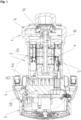
- Figure 1 shows a sectional view of the entire pump unit along its pump axis.
- the overall construction includes the hydraulic part 1 with pump impeller 1a, here designed as a centrifugal pump, in particular a heating circulation pump.
- the impeller 1a is connected to the rotor 6 of the electric motor 2 via the pump shaft 1b.
- the electric motor 2 consisting of rotor 6 and stator 5 is mounted within a motor housing 2a, which is axially connected directly to the pump housing 1c.
- a heat sink 4 which is used to remove heat from the electronics housing 3.
- the heat sink 4 is provided with individual cooling fins 4a, which extend from a heat sink base plate 4b in the direction of the axial end of the motor housing 2.
- the heat sink base plate is directly connected to the electronics housing 3 or is part of the electronics housing 3.
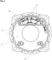
- the electrical connection of the electric motor 2 with the pump electronics is made via one or more stator plugs 7, which are connected via an opening 2b (see Figure 3 ) are accessible in the axial front side of the motor housing 2 facing the electronics housing.
- the electronics housing 3 comprises a corresponding hole 8 in the heat sink base plate 4b, which is aligned with the opening 2a of the motor housing when the pump is fully assembled. Electrical connection lines (not shown here) can thus be led from the electronics housing 3 through the heat sink 4 and the wall of the electric motor housing 2a to the stator plugs 7.
- further openings for other connections can be provided in the motor housing 2a and heat sink base plate 4b.
- Both the motor housing 2a and the heat sink 4 are made of aluminum and are therefore both thermally and electrically conductive. During pump operation, waste heat is generated by both the electric motor 2 and the electronics in the electronics housing 3, which must be dissipated to the outside environment.
- a thermal decoupling between the electronics housing 3 and the motor housing 2a is created by inserting an intermediate piece 10 between the heat sink 4 and the axial end face of the motor housing 2a facing the electronics housing 3.
- the intermediate piece 10 is made of rubber and therefore has a significantly lower thermal conductivity than the motor housing 2a or the heat sink 4.
- the intermediate piece enables direct contact between the heat sink 4 and the motor housing 2a and thus thermal decoupling.
- corresponding feedthrough openings 10a must be provided in the intermediate piece 10.
- the pressing 12 is achieved by a special geometric shape of the surfaces that contact the intermediate piece 10 in the area of the through-opening 10a.
- the front side of the motor housing 2a has a profile elevation 2c that runs all the way around the edge of the openings 2a and rises in the direction of the intermediate piece 10.
- the intermediate piece 10 can have a groove running around the through-opening 10a and extending perpendicularly from the top and/or bottom of the intermediate piece 10. extending apron 11a, 11b. These aprons 11a, 11b protrude into the hole 8 of the heat sink 4 and the opening 2a of the motor housing 2 and completely line the corresponding opening wall.
- the electrically insulating properties of the intermediate piece material serve as additional protection, ie insulation of the stator connection lines from the metallic motor housing wall or heat sink wall in the area of the holes 2a, 8. This prevents a possible electrical flashover from the current-carrying stator connections to the housing wall.
Landscapes
- Engineering & Computer Science (AREA)
- Mechanical Engineering (AREA)
- General Engineering & Computer Science (AREA)
- Physics & Mathematics (AREA)
- Thermal Sciences (AREA)
- Structures Of Non-Positive Displacement Pumps (AREA)
Description
- Die Erfindung betrifft eine Pumpe umfassend einen Antriebsmotor, wenigstens ein Elektronikgehäuse sowie wenigstens einen Kühlkörper zur Wärmeabfuhr aus dem Elektronikgehäuse, wobei zwischen Kühlkörper und Motorgehäuse ein Zwischenstück zur thermischen Entkopplung des Kühlkörpers von dem Motorgehäuse eingebracht ist, und wobei das Zwischenstück wenigstens eine Durchführungsöffnung zur Durchführung wenigstens einer Komponente zwischen Motorgehäuse und Kühlkörper aufweist. Pumpen bestehen aus unterschiedlichen Komponenten, die unabhängig voneinander während des Pumpenbetriebs Abwärme erzeugen. Als Pumpenantrieb wird oftmals ein Elektromotor eingesetzt, dessen im Betrieb erzeugte Abwärme über das Motorgehäuse abgeführt wird. Zur Steuerung/Regelung der Pumpen bzw. des Elektromotors ist eine Steuerungselektronik, insbesondere ein Frequenzumrichter vorgesehen, die in einem gesonderten Elektronikgehäuse untergebracht ist. Das Elektronikgehäuse wird im Sinne eines kompakten Pumpenaufbaus am Motorgehäuse installiert, wie offenbart in
WO2013135465 A1 . Zur Reduzierung der gegenseitigen thermischen Belastung müssen beide Gehäuse, d.h. das Motor- sowie das Elektronikgehäuse voneinander thermisch entkoppelt werden. Letzteres ist in der Regel mit einem eigenen Kühlkörper zur Optimierung der Wärmeabfuhr ausgestattet. Für die notwendige thermische Entkopplung wurde in der Vergangenheit ein Zwischenstück zwischen Kühlkörper des Elektronikgehäuses und dem Motorgehäuse eingesetzt. Das Zwischenstück war beispielsweise ein Kunststoffteil, das die zugewandten Seiten des Kühlkörpers sowie des Motorgehäuses voneinander trennt. - Da zwischen der Elektronik der Pumpe und dem Elektromotor Verbindungsleitungen notwendig sind, bspw. für den Statoranschluss an die Leistungselektronik des Frequenzumrichters, müssen sowohl das Zwischenstück, das Elektronikgehäuse mit Kühlkörper sowie das Motorgehäuse Öffnungen zur Bereitstellung von Durchführungsöffnungen für die Verbindungsleitungen aufweisen. Ein Eintritt von Spritzwasser über diese Durchführungsöffnungen muss verhindert werden, weshalb diese Öffnungen durch gesonderte Maßnahmen gegenüber der Umgebung abzudichten sind. In der Vergangenheit wurde entweder eine Dichtlippe direkt in den Bereich des Zwischenstückes aufgespritzt oder aber ein separates Dichtungselement, wie bspw. ein O-Ring, eingesetzt. Diese Lösung erhöht jedoch den Montageaufwand sowie die Herstellungskosten der Pumpe.
- Das Ziel der vorliegenden Erfindung war es, die bisherige Vorgehensweise zu vereinfachen und eine verbesserte Abdichtung im Bereich der Durchführungsöffnungen des Zwischenstückes zu erreichen.
- Gelöst wird diese Aufgabe durch eine Pumpe gemäß den Merkmalen des Anspruchs 1. Vorteilhafte Ausführungen der Pumpe sind Gegenstand der abhängigen Ansprüche.
- Erfindungsgemäß wird vorgeschlagen, das Zwischenstück, welches zwischen Motorgehäuse und Kühlkörper eingebracht ist, aus einem elastischen Material zu fertigen. Die Elastizität des Zwischenstücks erlaubt dessen definierte Verpressung im Bereich der Durchführungsöffnungen, was durch eine spezielle Geometrie, d.h. geeignete Ausformung des Kühlkörpers, des Motorgehäuses und/oder des Zwischenstückes erreicht wird. Die Ausformung von Presskanten an Kühlkörper und/oder Motorgehäuse bzw. eine Erhöhung der Materialstärke des Zwischenstückes im Bereich der Durchführungsöffnung des Zwischenstückes führt beim Zusammensetzen der Pumpe zu eine erhöhten Verpressung des Zwischenstückes um seine Durchführungsöffnung. Durch den dort stärker verpressten Flächenabschnitt des Zwischenstückes wird Dichtigkeit in diesem Bereich um die Durchführungsöffnung gezielt erhöht, so dass ein ausreichender Spritzwasserschutz gewährleistet und ein Wassereintritt von außen über die Durchführungsöffnung in das Elektronikgehäuse und/oder das Motorgehäuse verhindert wird. An Stelle einer separaten Dichtung bzw. dem Aufspritzen von Dichtungselementen wird auf diese Weise ein deutlich einfacherer Aufbau realisiert mit gleichzeitig einhergehender Einsparung bei den Herstellungskosten.
- Vorteilhaft ist es, das Motorgehäuse und/oder den Kühlkörper des Elektronikgehäuses im Bereich ihrer gegenseitigen Kontaktflächen mit einer Profilerhebung im Bereich der Durchführungsöffnungen des Zwischenstücks auszustatten. Eine solche Profilerhebung sorgt für die geometriebedingte Verpressung des Zwischenstückes im anliegenden Bereich. Von Vorteil ist eine wulstartige Profilerhebung an der Kontaktfläche des Motorgehäuses und/oder des Kühlkörpers. Von Vorteil ist es ebenso, wenn eine solche Profilerhebung um eine Öffnung des Motorgehäuses und/oder des Kühlkörpers verläuft. Die Öffnung des Motorgehäuses und/oder des Kühlkörpers dienen in Verbindung mit der Durchführungsöffnung des Zwischenstückes zur Durchführung der wenigstens einen Komponente zwischen Motorgehäuse und Kühlkörper.
- Das Zwischenstück ist vorteilhafterweise aus einem thermisch isolierenden Material gefertigt, sodass eine thermische Entkopplung zwischen den beiden Komponenten, d. h. dem Motorgehäuse sowie dem Kühlkörper bzw. dem Elektronikgehäuse erreicht wird. Darüber hinaus kann es von besonderer Bedeutung sein, das Material für das Zwischenstück zusätzlich aus einem elektrisch nichtleitenden Material zu fertigen. In der Regel sind der Kühlkörper und/oder das Motorgehäuse aus einem elektrisch leitenden Material wie Metall, insbesondere Aluminium gefertigt. Bei der Durchführung elektrischer Bauteile durch die entsprechenden Öffnungen im Motorgehäuse bzw. Kühlkörper ist eine elektrische Isolation evident wichtig, was unter anderem durch einen Mindestabstand zwischen Leitung und Öffnungswandung erreicht wird. Das Zwischenstück, welches aus einem elektrisch isolierenden Material gefertigt ist, kann zur zusätzlichen Isolierung des Durchgangsbereichs gegenüber einer durchgeführten Elektroleitung dienen. Von Vorteil ist es hierzu, wenn das Zwischenstück im Bereich der Durchführungsöffnung eine, sich von der Oberfläche des Zwischenstücks erstreckende Schürze aufweist, die vorzugsweise in die anschließenden Öffnungen des Kühlkörpers und/oder des Motorgehäuses hineinragt. Die Schürze dient demzufolge als eine Art Isolationsmantel, der sich um die durchgeführte elektrische Leitung erstreckt. Besonders bevorzugt ist es, wenn sich die Schürze passgenau an die Öffnungswand des Kühlkörpers und/oder des Motorgehäuses anlegt, d. h. den Öffnungsumfang des Kühlkörpers und/oder des Motorgehäuses idealerweise vollständig auskleidet.
- Es besteht die Möglichkeit, das Elektronikgehäuse bzw. den dort vorgesehenen Kühlkörper umfangsseitig an das Motorgehäuse sowie alternativ oder zusätzlich ans axiale Stirnende des Motorgehäuses anzubringen. Bevorzugt ist es in diesem Fall, wenn das Zwischenstück am axialen Ende, d. h. der dortigen Stirnseite des Motorgehäuses angebracht ist, diese wiederrum mit dem Kühlkörper in Verbindung steht. Dabei kann vorgesehen sein, dass die Kontaktfläche des Kühlkörpers mit dem Zwischenstück überwiegend durch Kühlrippen gebildet ist.
- Bei der Pumpe kann es sich um einen beliebigen Pumpentyp mit integrierter Elektroniksteuerung handeln. Bevorzugt ist die Pumpe als Kreiselpumpe, besonders bevorzugt als Heizungsumwälzpumpe, ausgestaltet, die durch die integrale Steuereinheit vorzugsweise drehzahlgeregelt arbeitet.
- Weitere Vorteile und Eigenschaften der Erfindung sollen nachfolgend anhand eines in den Figuren dargestellten Ausführungsbeispiels näher erläutert werden. Es zeigen:
- Figur 1:
- eine Schnittdarstellung entlang der axialen Motorachse der Pumpe,
- Figur 2:
- eine Detaildarstellung des Kontaktbereichs zwischen Motorgehäuse und Kühlkörper sowie dem dazwischen eingelegten Zwischenstück und
- Figur 3:
- eine Draufsicht auf die axiale Stirnseite des Motorgehäuses.
-
Figur 1 zeigt eine Schnittdarstellung des gesamten Pumpenaggregats entlang seiner Pumpenachse. Die Gesamtkonstruktion umfasst den Hydraulikteil 1 mit Pumpenlaufrad 1a, hier ausgeführt als Kreiselpumpe, insbesondere Heizungsumwälzpumpe. Das Laufrad 1a ist über die Pumpenwelle 1b mit dem Rotor 6 des Elektromotors 2 verbunden. - Der Elektromotor 2 bestehend aus Rotor 6 und Stator 5 ist innerhalb eines Motorgehäuses 2a gelagert, das sich axial direkt an das Pumpengehäuse 1c anschließt. Am axialen, der Pumpe 1 abgewandten Ende des Motorgehäuses 2a schließt sich ein Kühlkörper 4 an, der zum Wärmeabtrag aus dem Elektronikgehäuse 3 dient. Der Kühlkörper 4 ist mit einzelnen Kühlrippen 4a versehen, die sich von einer Kühlkörpergrundplatte 4b in Richtung des axialen Endes des Motorgehäuses 2 erstrecken. Die Kühlkörpergrundplatte ist unmittelbar mit dem Elektronikgehäuse 3 verbunden bzw. ist Bestandteil des Elektronikgehäuses 3.
- Die elektrische Anbindung des Elektromotors 2 mit der Pumpenelektronik, bspw. der Leistungselektronik eines Frequenzumrichters, erfolgt über ein oder mehrere Statorstecker 7, die über eine Öffnung 2b (siehe
Figur 3 ) in der axialen, dem Elektronikgehäuse zugewandten Stirnseite des Motorgehäuses 2 zugänglich sind. Das Elektronikgehäuse 3 umfasst eine korrespondierende Bohrung 8 in der Kühlkörpergrundplatte 4b, die bei vollständig montierter Pumpe fluchtend zur Öffnung 2a des Motorgehäuses liegt. Elektrische Verbindungsleitungen (hier nicht dargestellt) können so vom Elektronikgehäuse 3 durch den Kühlkörper 4 und die Wand des Elektromotorgehäuses 2a bis zu den Statorsteckern 7 durchgeführt werden. Neben den Öffnungen für den Statoranschluss können weitere Öffnungen für sonstige Verbindungen im Motorgehäuse 2a und Kühlkörpergrundplatte 4b vorgesehen sein. - Sowohl das Motorgehäuse 2a als auch der Kühlkörper 4 sind aus Aluminium gefertigt und dadurch sowohl thermisch als auch elektrisch leitend. Während des Pumpenbetriebes wird sowohl vom Elektromotor 2 als auch der Elektronik im Elektronikgehäuse 3 Abwärme erzeugt, die an die Außenumgebung abgeführt werden muss.
- Zur Vermeidung einer gegenseitigen thermischen Beeinflussung der Elektronik und Motor 2 wird eine thermische Entkopplung zwischen Elektronikgehäuse 3 und Motorgehäuse 2a geschaffen, indem zwischen dem Kühlkörper 4 und der axialen, dem Elektronikgehäuse 3 zugewandten Stirnseite des Motorgehäuses 2a ein Zwischenstück 10 eingesetzt wird. Das Zwischenstück 10 ist aus Gummi gefertigt und hat daher eine deutlich geringere Wärmeleitfähigkeit als das Motorgehäuse 2a bzw. der Kühlkörper 4. Durch das Zwischenstück wird eine direkte Kontaktierung von Kühlkörper 4 und Motorgehäuse 2a und damit eine thermische Entkopplung erreicht. Für die Durchführung der elektrischen und sonstigen Verbindungsleitungen zwischen Elektronikgehäuse 3 und Motorgehäuse 2a müssen korrespondierende Durchführungsöffnungen 10a im Zwischenstück 10 vorgesehen sein.
- Eine Anforderung, die an Pumpen, insbesondere Heizungsumwälzpumpen gestellt wird, ist die des Spritzwasserschutzes, bspw. gemäß IP44. Zur Umsetzung dieser Vorgabe muss auch der Bereich der vorstehend angesprochenen Leitungsdurchführung geschützt werden. Für die zusätzliche Abdichtung im Bereich der Leitungsdurchführung wird eine stärkere Verpressung 12 des elastischen Materials des Zwischenstückes 10 um den Bereich der Durchführungsöffnungen 10a gezielt erzeugt. Durch diese verstärkte Materialverpressung 12 im Bereich um die Durchführungsöffnung 10a kann diese besser nach aussen hin abgedichtet werden und ein Eintritt von Spritzwasser in das Elektronikgehäuse und/oder Motorgehäuse wird effektiv verhindert. Insbesondere kommt diese Lösung ohne zusätzliche Einbringung separater Dichtungselemente aus.
- Die Verpressung 12 wird durch eine spezielle geometrische Ausformung der das Zwischenstück 10 im Bereich der Durchführungsöffnung 10a kontaktierenden Oberflächen erzielt. Im hier vorliegenden Ausführungsbeispiel zeigt die Stirnseite des Motorgehäuses 2a eine um den Rand der Öffnungen 2a vollumfänglich verlaufende Profilerhebungen 2c, die sich in Richtung des Zwischenstücks 10 erhebt. Beim Zusammensetzen der Pumpe wird so der durch das Motorgehäuse 2a auf das eingesetzte Zwischenstück 10 aufgebrachte Druck um die Durchführungsöffnung 10a verstärkt, was zur gewünschten Verpressung im Randbereich des Zwischenstückes 10 um seine Durchführungsöffnung 10a führt. Auf das Einsetzen zusätzlicher O-Ringe bzw. das Aufspritzen von Dichtungslippen kann verzichtet werden, weshalb die erfindungsgemäße Gesamtkonstruktion kostengünstiger wird.
- Ergänzend kann das Zwischenstück 10 eine um die Durchführungsöffnung 10a verlaufende und sich senkrecht von der Ober- und/oder Unterseite des Zwischenstückes 10 erstreckende Schürze 11a, 11b aufweisen. Diese Schürzen 11a, 11b ragen in die Bohrung 8 des Kühlkörpers 4 sowie die Öffnung 2a des Motorgehäuses 2 hinein und kleiden dort die entsprechende Öffnungswand vollumfänglich aus. Die elektrisch isolierenden Eigenschaften des Zwischenstückmaterials dienen als zusätzlicher Schutz, d.h. Isolation der Statorverbindungsleitungen gegenüber der metallischen Motorgehäusewand bzw. Kühlkörperwand im Bereich der Bohrungen 2a, 8. Dadurch wird ein möglicher elektrischer Überschlag von den stromführenden Statoranschlüssen auf die Gehäusewand vermieden.
Claims (11)
- Pumpe umfassend einen Antriebsmotor, wenigstens ein Elektronikgehäuse (3) sowie wenigstens einen Kühlkörper (4) zur Wärmeabfuhr aus dem Elektronikgehäuse (3), wobei zwischen Kühlkörper (4) und Motorgehäuse (2a) des Antriebsmotors (2) ein Zwischenstück (10) zur thermischen Entkopplung des Kühlkörpers (4) von dem Motorgehäuse (2a) eingebracht ist, und wobei das Zwischenstück (10) wenigstens eine Durchführungsöffnung (10a) zur Durchführung wenigstens einer Komponente zwischen Motorgehäuse (2a) und Kühlkörper (4) aufweist,
dadurch gekennzeichnet,
dass das Zwischenstück (10) aus einem elastischen Material gefertigt ist und das Zwischenstück (10) im Bereich um die wenigstens eine Durchführungsöffnung (10a) geometriebedingt verpresst ist, um den Bereich der Durchführungsöffnung (10a) gegenüber der Umgebung abzudichten. - Pumpe nach Anspruch 1, dadurch gekennzeichnet, dass die Kontaktfläche des Motorgehäuses (2a) und/oder des Kühlkörpers (4) im Bereich der Durchführungsöffnung (10a) des Zwischenstücks (10) eine Profilerhebung (2c), insbesondere wulstartige Profilerhebung (2c) aufweist, um die geometriebedingte Verpressung (12) des Zwischenstücks (10) im Bereich der Durchführungsöffnung (10a) zu erzeugen.
- Pumpe nach Anspruch 2, dadurch gekennzeichnet, dass die Profilerhebung (2c) ringartig um eine, sich an die Durchführungsöffnung (10a) des Zwischenstückes (10) anschliessende Öffnung (2b, 8) des Motorgehäuses (2a) und/oder des Kühlkörpers (4) verläuft.
- Pumpe nach einem der vorstehenden Ansprüche, dadurch gekennzeichnet, dass das Zwischenstück (10) aus einem elektrisch und/oder thermisch isolierenden Material besteht.
- Pumpe nach einem der vorstehenden Ansprüche, dadurch gekennzeichnet, dass das Zwischenstück (10) aus Gummi besteht.
- Pumpe nach einem der vorstehenden Ansprüche, dadurch gekennzeichnet, dass das Zwischenstück (10) im Bereich der Durchführungsöffnung (10a) wenigstens eine, sich von der Oberfläche erstreckende Schürze (11a, 11b) aufweist, die in eine an die Durchführungsöffnung (10a) anschliessende Öffnung (8, 2b) des Kühlkörpers (4) und/oder des Motorgehäuses (2a) hineinragt.
- Pumpe nach Anspruch 6, dadurch gekennzeichnet, dass sich die Schürze (11a, 11b) passgenau an die Öffnungswand des Kühlkörpers (4) und/oder des Motorgehäuses (2a) anlegt, insbesondere den Umfang der Öffnung (8, 2b) des Kühlkörpers (4) und/oder des Motorgehäuses (2a) auskleidet.
- Pumpe nach einem der vorstehenden Ansprüche, dadurch gekennzeichnet, dass die Öffnungen (10a, 2b, 8) im Zwischenstück (10), Motorgehäuse (2a) und Kühlkörper (4) zur Durchführung wenigstens einer elektrischen Verbindungsleitung (7) dient, insbesondere zur Durchführung der elektrischen Verbindung zwischen Stator und Pumpenelektronik.
- Pumpe nach einem der vorstehenden Ansprüche, dadurch gekennzeichnet, dass der Kühlkörper (4) und das Motorgehäuse (2a) aus Metall, insbesondere Aluminium bestehen.
- Pumpe nach einem der vorstehenden Ansprüche, dadurch gekennzeichnet, dass das Zwischenstück (10) zwischen einer axialen Stirnseite des Motorgehäuses (2a) und dem Kühlkörper (4) eingebracht und/oder die dem Zwischenstück (10) zugewandte Kontaktseite des Kühlkörpers (4) mit Kühlrippen (4a) versehen ist, deren freie Enden das Zwischenstück (10) kontaktieren.
- Pumpe nach einem der vorstehenden Ansprüche, dadurch gekennzeichnet, dass die Pumpe eine Kreiselpumpe, insbesondere Heizungsumwälzpumpe, ist.
Applications Claiming Priority (2)
| Application Number | Priority Date | Filing Date | Title |
|---|---|---|---|
| DE102021000933.9A DE102021000933A1 (de) | 2021-02-22 | 2021-02-22 | Pumpe mit Elektronikgehäuse und Kühlkörper |
| PCT/EP2022/054235 WO2022175520A1 (de) | 2021-02-22 | 2022-02-21 | Pumpe mit elektronikgehäuse und kühlkörper |
Publications (3)
| Publication Number | Publication Date |
|---|---|
| EP4295050A1 EP4295050A1 (de) | 2023-12-27 |
| EP4295050B1 true EP4295050B1 (de) | 2025-02-19 |
| EP4295050C0 EP4295050C0 (de) | 2025-02-19 |
Family
ID=80595315
Family Applications (1)
| Application Number | Title | Priority Date | Filing Date |
|---|---|---|---|
| EP22706841.8A Active EP4295050B1 (de) | 2021-02-22 | 2022-02-21 | Pumpe mit elektronikgehäuse und kühlkörper |
Country Status (4)
| Country | Link |
|---|---|
| EP (1) | EP4295050B1 (de) |
| CN (1) | CN116981849A (de) |
| DE (1) | DE102021000933A1 (de) |
| WO (1) | WO2022175520A1 (de) |
Families Citing this family (2)
| Publication number | Priority date | Publication date | Assignee | Title |
|---|---|---|---|---|
| DE102024101278A1 (de) | 2024-01-17 | 2025-07-17 | KSB SE & Co. KGaA | Geräuschoptimiertes System zum Antrieb einer Kreiselpumpe |
| DE102024101239A1 (de) | 2024-01-17 | 2025-07-17 | KSB SE & Co. KGaA | Geräuschoptimiertes System zum Antrieb einer Kreiselpumpe |
Family Cites Families (8)
| Publication number | Priority date | Publication date | Assignee | Title |
|---|---|---|---|---|
| DE3642724A1 (de) * | 1986-12-13 | 1988-06-23 | Grundfos Int | Elektromotor mit einem frequenzumrichter zur steuerung der motorbetriebsgroessen |
| US5763969A (en) | 1996-11-14 | 1998-06-09 | Reliance Electric Industrial Company | Integrated electric motor and drive system with auxiliary cooling motor and asymmetric heat sink |
| DE102005032969B4 (de) | 2005-07-14 | 2010-05-12 | Siemens Ag | Umrichtermotor |
| DE102005041136B4 (de) * | 2005-08-30 | 2023-11-02 | Sew-Eurodrive Gmbh & Co Kg | Umrichtermotor und Verfahren |
| DE102007045815A1 (de) * | 2007-09-25 | 2009-04-09 | Magna Powertrain Ag & Co Kg | Getriebeeinheit |
| EP2607709B1 (de) * | 2011-12-23 | 2015-12-23 | Grundfos Holding A/S | Elektromotor |
| EP2639940B1 (de) | 2012-03-15 | 2014-09-24 | Grundfos Holding A/S | Elektromotor |
| CN208904821U (zh) * | 2018-11-22 | 2019-05-24 | 安徽鸿创新能源动力有限公司 | 电动汽车电机后端盖出线结构 |
-
2021
- 2021-02-22 DE DE102021000933.9A patent/DE102021000933A1/de active Pending
-
2022
- 2022-02-21 WO PCT/EP2022/054235 patent/WO2022175520A1/de not_active Ceased
- 2022-02-21 EP EP22706841.8A patent/EP4295050B1/de active Active
- 2022-02-21 CN CN202280016171.6A patent/CN116981849A/zh active Pending
Also Published As
| Publication number | Publication date |
|---|---|
| EP4295050C0 (de) | 2025-02-19 |
| CN116981849A (zh) | 2023-10-31 |
| DE102021000933A1 (de) | 2022-08-25 |
| EP4295050A1 (de) | 2023-12-27 |
| WO2022175520A1 (de) | 2022-08-25 |
Similar Documents
| Publication | Publication Date | Title |
|---|---|---|
| DE112017003154B4 (de) | Elektrische leitungseinführungs-teilstruktur eines elektrischen kompressors und elektrischer kompressor und damit bereitgestellte elektrische abschirmleitung | |
| EP1006766B2 (de) | Elektronische Vorrichtung | |
| DE102010041918B4 (de) | Statoranordnung umfassend einen Klemmenblock für eine elektrische Maschine | |
| EP4295050B1 (de) | Pumpe mit elektronikgehäuse und kühlkörper | |
| DE102016216848B4 (de) | Hochfrequenzentladungszündvorrichtung | |
| EP1396180B1 (de) | Gehäuse für ein elektrisches gerät | |
| EP1447900B1 (de) | Stromversorgungseinheit | |
| EP3762964B1 (de) | Kühleinrichtung zur kühlung eines leistungsbauelements | |
| DE202011005667U1 (de) | Kompakte Sammelschienenanordnung, Schaltvorrichtung und Stromverteilungssytem | |
| DE102013004189B4 (de) | Elektrogerät mit Gehäuse und auf dem Gehäuse aufsetzbarem Deckel | |
| DE20301773U1 (de) | Elektrische Einrichtung | |
| DE102019005171A1 (de) | Elektromotor, insbesondere Außenläufermotor | |
| EP3804482B1 (de) | Elektrisches oder elektronisches gerät umfassend ein gehäuse mit zwei untereinander elektromagnetisch abgeschirmten bereichen | |
| DE202018103164U1 (de) | Elektrisches oder elektronisches Gerät umfassend ein Gehäuse mit zwei untereinander elektromagnetisch abgeschirmten Bereichen | |
| EP3716408B1 (de) | Flexibler berührungsschutz für elektrischen anschluss | |
| DE102017001929A1 (de) | Elektronikmodul für einen Elektromotor, insbesondere eines Pumpenaggregats | |
| DE102016206234A1 (de) | Stromschiene für einen Wechselrichter, Wechselrichter und Kraftfahrzeugantriebsystem | |
| DE102018215522A1 (de) | Zwischenkreiskondensator für eine Leistungselektronikanordnung sowie Leistungselektronikanordnung mit dem Zwischenkreiskondensator | |
| WO2013167322A1 (de) | Anordnung zur wärmeableitung für ein kunststoffgehäuse mit darin angeordneten elektronischen bauelementen | |
| DE19904279B4 (de) | Halbleitervorrichtung | |
| DE4002244C1 (de) | ||
| DE102016100997A1 (de) | Stromschienenmodul und elektrische Schaltung | |
| EP3819980B1 (de) | Batteriesystem | |
| DE112023000485T5 (de) | Halbleitermodul und leistungsumwandlungsvorrichtung | |
| DE7505830U (de) | Vorrichtung zum hochspannungsfesten und gut waermeleitenden einbau von halbleiter-bauelementen |
Legal Events
| Date | Code | Title | Description |
|---|---|---|---|
| STAA | Information on the status of an ep patent application or granted ep patent |
Free format text: STATUS: UNKNOWN |
|
| STAA | Information on the status of an ep patent application or granted ep patent |
Free format text: STATUS: THE INTERNATIONAL PUBLICATION HAS BEEN MADE |
|
| PUAI | Public reference made under article 153(3) epc to a published international application that has entered the european phase |
Free format text: ORIGINAL CODE: 0009012 |
|
| STAA | Information on the status of an ep patent application or granted ep patent |
Free format text: STATUS: REQUEST FOR EXAMINATION WAS MADE |
|
| 17P | Request for examination filed |
Effective date: 20230707 |
|
| AK | Designated contracting states |
Kind code of ref document: A1 Designated state(s): AL AT BE BG CH CY CZ DE DK EE ES FI FR GB GR HR HU IE IS IT LI LT LU LV MC MK MT NL NO PL PT RO RS SE SI SK SM TR |
|
| DAV | Request for validation of the european patent (deleted) | ||
| DAX | Request for extension of the european patent (deleted) | ||
| GRAP | Despatch of communication of intention to grant a patent |
Free format text: ORIGINAL CODE: EPIDOSNIGR1 |
|
| STAA | Information on the status of an ep patent application or granted ep patent |
Free format text: STATUS: GRANT OF PATENT IS INTENDED |
|
| INTG | Intention to grant announced |
Effective date: 20241001 |
|
| GRAS | Grant fee paid |
Free format text: ORIGINAL CODE: EPIDOSNIGR3 |
|
| GRAA | (expected) grant |
Free format text: ORIGINAL CODE: 0009210 |
|
| STAA | Information on the status of an ep patent application or granted ep patent |
Free format text: STATUS: THE PATENT HAS BEEN GRANTED |
|
| AK | Designated contracting states |
Kind code of ref document: B1 Designated state(s): AL AT BE BG CH CY CZ DE DK EE ES FI FR GB GR HR HU IE IS IT LI LT LU LV MC MK MT NL NO PL PT RO RS SE SI SK SM TR |
|
| REG | Reference to a national code |
Ref country code: GB Ref legal event code: FG4D Free format text: NOT ENGLISH |
|
| REG | Reference to a national code |
Ref country code: CH Ref legal event code: EP |
|
| REG | Reference to a national code |
Ref country code: DE Ref legal event code: R096 Ref document number: 502022002937 Country of ref document: DE |
|
| REG | Reference to a national code |
Ref country code: IE Ref legal event code: FG4D Free format text: LANGUAGE OF EP DOCUMENT: GERMAN |
|
| U01 | Request for unitary effect filed |
Effective date: 20250227 |
|
| U07 | Unitary effect registered |
Designated state(s): AT BE BG DE DK EE FI FR IT LT LU LV MT NL PT RO SE SI Effective date: 20250307 |
|
| U20 | Renewal fee for the european patent with unitary effect paid |
Year of fee payment: 4 Effective date: 20250307 |
|
| PG25 | Lapsed in a contracting state [announced via postgrant information from national office to epo] |
Ref country code: RS Free format text: LAPSE BECAUSE OF FAILURE TO SUBMIT A TRANSLATION OF THE DESCRIPTION OR TO PAY THE FEE WITHIN THE PRESCRIBED TIME-LIMIT Effective date: 20250519 |
|
| PG25 | Lapsed in a contracting state [announced via postgrant information from national office to epo] |
Ref country code: PL Free format text: LAPSE BECAUSE OF FAILURE TO SUBMIT A TRANSLATION OF THE DESCRIPTION OR TO PAY THE FEE WITHIN THE PRESCRIBED TIME-LIMIT Effective date: 20250219 |
|
| PG25 | Lapsed in a contracting state [announced via postgrant information from national office to epo] |
Ref country code: ES Free format text: LAPSE BECAUSE OF FAILURE TO SUBMIT A TRANSLATION OF THE DESCRIPTION OR TO PAY THE FEE WITHIN THE PRESCRIBED TIME-LIMIT Effective date: 20250219 |
|
| PG25 | Lapsed in a contracting state [announced via postgrant information from national office to epo] |
Ref country code: IS Free format text: LAPSE BECAUSE OF FAILURE TO SUBMIT A TRANSLATION OF THE DESCRIPTION OR TO PAY THE FEE WITHIN THE PRESCRIBED TIME-LIMIT Effective date: 20250619 Ref country code: NO Free format text: LAPSE BECAUSE OF FAILURE TO SUBMIT A TRANSLATION OF THE DESCRIPTION OR TO PAY THE FEE WITHIN THE PRESCRIBED TIME-LIMIT Effective date: 20250519 |
|
| PG25 | Lapsed in a contracting state [announced via postgrant information from national office to epo] |
Ref country code: HR Free format text: LAPSE BECAUSE OF FAILURE TO SUBMIT A TRANSLATION OF THE DESCRIPTION OR TO PAY THE FEE WITHIN THE PRESCRIBED TIME-LIMIT Effective date: 20250219 |
|
| PG25 | Lapsed in a contracting state [announced via postgrant information from national office to epo] |
Ref country code: GR Free format text: LAPSE BECAUSE OF FAILURE TO SUBMIT A TRANSLATION OF THE DESCRIPTION OR TO PAY THE FEE WITHIN THE PRESCRIBED TIME-LIMIT Effective date: 20250520 |
|
| PG25 | Lapsed in a contracting state [announced via postgrant information from national office to epo] |
Ref country code: SM Free format text: LAPSE BECAUSE OF FAILURE TO SUBMIT A TRANSLATION OF THE DESCRIPTION OR TO PAY THE FEE WITHIN THE PRESCRIBED TIME-LIMIT Effective date: 20250219 |
|
| PG25 | Lapsed in a contracting state [announced via postgrant information from national office to epo] |
Ref country code: CZ Free format text: LAPSE BECAUSE OF FAILURE TO SUBMIT A TRANSLATION OF THE DESCRIPTION OR TO PAY THE FEE WITHIN THE PRESCRIBED TIME-LIMIT Effective date: 20250219 |
|
| PG25 | Lapsed in a contracting state [announced via postgrant information from national office to epo] |
Ref country code: SK Free format text: LAPSE BECAUSE OF FAILURE TO SUBMIT A TRANSLATION OF THE DESCRIPTION OR TO PAY THE FEE WITHIN THE PRESCRIBED TIME-LIMIT Effective date: 20250219 |
|
| PG25 | Lapsed in a contracting state [announced via postgrant information from national office to epo] |
Ref country code: MC Free format text: LAPSE BECAUSE OF FAILURE TO SUBMIT A TRANSLATION OF THE DESCRIPTION OR TO PAY THE FEE WITHIN THE PRESCRIBED TIME-LIMIT Effective date: 20250219 |
|
| PLBE | No opposition filed within time limit |
Free format text: ORIGINAL CODE: 0009261 |
|
| STAA | Information on the status of an ep patent application or granted ep patent |
Free format text: STATUS: NO OPPOSITION FILED WITHIN TIME LIMIT |
|
| REG | Reference to a national code |
Ref country code: CH Ref legal event code: L10 Free format text: ST27 STATUS EVENT CODE: U-0-0-L10-L00 (AS PROVIDED BY THE NATIONAL OFFICE) Effective date: 20251231 |
|
| PG25 | Lapsed in a contracting state [announced via postgrant information from national office to epo] |
Ref country code: IE Free format text: LAPSE BECAUSE OF NON-PAYMENT OF DUE FEES Effective date: 20250221 |
|
| 26N | No opposition filed |
Effective date: 20251120 |
|
| REG | Reference to a national code |
Ref country code: CH Ref legal event code: U11 Free format text: ST27 STATUS EVENT CODE: U-0-0-U10-U11 (AS PROVIDED BY THE NATIONAL OFFICE) Effective date: 20260301 |
|
| U20 | Renewal fee for the european patent with unitary effect paid |
Year of fee payment: 5 Effective date: 20260222 |
|
| PGFP | Annual fee paid to national office [announced via postgrant information from national office to epo] |
Ref country code: GB Payment date: 20260226 Year of fee payment: 5 |
|
| PGFP | Annual fee paid to national office [announced via postgrant information from national office to epo] |
Ref country code: CH Payment date: 20260301 Year of fee payment: 5 |