EP4294579B1 - Abzugshebelabgabevorrichtung mit ventilmitteln - Google Patents
Abzugshebelabgabevorrichtung mit ventilmitteln Download PDFInfo
- Publication number
- EP4294579B1 EP4294579B1 EP22707848.2A EP22707848A EP4294579B1 EP 4294579 B1 EP4294579 B1 EP 4294579B1 EP 22707848 A EP22707848 A EP 22707848A EP 4294579 B1 EP4294579 B1 EP 4294579B1
- Authority
- EP
- European Patent Office
- Prior art keywords
- wall
- valve
- sleeve
- trigger
- suction
- Prior art date
- Legal status (The legal status is an assumption and is not a legal conclusion. Google has not performed a legal analysis and makes no representation as to the accuracy of the status listed.)
- Active
Links
Images







Classifications
-
- B—PERFORMING OPERATIONS; TRANSPORTING
- B05—SPRAYING OR ATOMISING IN GENERAL; APPLYING FLUENT MATERIALS TO SURFACES, IN GENERAL
- B05B—SPRAYING APPARATUS; ATOMISING APPARATUS; NOZZLES
- B05B11/00—Single-unit hand-held apparatus in which flow of contents is produced by the muscular force of the operator at the moment of use
- B05B11/0005—Components or details
- B05B11/0037—Containers
- B05B11/0039—Containers associated with means for compensating the pressure difference between the ambient pressure and the pressure inside the container, e.g. pressure relief means
- B05B11/0044—Containers associated with means for compensating the pressure difference between the ambient pressure and the pressure inside the container, e.g. pressure relief means compensating underpressure by ingress of atmospheric air into the container, i.e. with venting means
-
- B—PERFORMING OPERATIONS; TRANSPORTING
- B05—SPRAYING OR ATOMISING IN GENERAL; APPLYING FLUENT MATERIALS TO SURFACES, IN GENERAL
- B05B—SPRAYING APPARATUS; ATOMISING APPARATUS; NOZZLES
- B05B11/00—Single-unit hand-held apparatus in which flow of contents is produced by the muscular force of the operator at the moment of use
- B05B11/01—Single-unit hand-held apparatus in which flow of contents is produced by the muscular force of the operator at the moment of use characterised by the means producing the flow
- B05B11/10—Pump arrangements for transferring the contents from the container to a pump chamber by a sucking effect and forcing the contents out through the dispensing nozzle
- B05B11/1042—Components or details
- B05B11/1066—Pump inlet valves
- B05B11/1067—Pump inlet valves actuated by pressure
- B05B11/1069—Pump inlet valves actuated by pressure the valve being made of a resiliently deformable material or being urged in a closed position by a spring
-
- B—PERFORMING OPERATIONS; TRANSPORTING
- B05—SPRAYING OR ATOMISING IN GENERAL; APPLYING FLUENT MATERIALS TO SURFACES, IN GENERAL
- B05B—SPRAYING APPARATUS; ATOMISING APPARATUS; NOZZLES
- B05B11/00—Single-unit hand-held apparatus in which flow of contents is produced by the muscular force of the operator at the moment of use
- B05B11/01—Single-unit hand-held apparatus in which flow of contents is produced by the muscular force of the operator at the moment of use characterised by the means producing the flow
- B05B11/10—Pump arrangements for transferring the contents from the container to a pump chamber by a sucking effect and forcing the contents out through the dispensing nozzle
- B05B11/1001—Piston pumps
- B05B11/1009—Piston pumps actuated by a lever
- B05B11/1011—Piston pumps actuated by a lever without substantial movement of the nozzle in the direction of the pressure stroke
-
- B—PERFORMING OPERATIONS; TRANSPORTING
- B05—SPRAYING OR ATOMISING IN GENERAL; APPLYING FLUENT MATERIALS TO SURFACES, IN GENERAL
- B05B—SPRAYING APPARATUS; ATOMISING APPARATUS; NOZZLES
- B05B11/00—Single-unit hand-held apparatus in which flow of contents is produced by the muscular force of the operator at the moment of use
- B05B11/01—Single-unit hand-held apparatus in which flow of contents is produced by the muscular force of the operator at the moment of use characterised by the means producing the flow
- B05B11/10—Pump arrangements for transferring the contents from the container to a pump chamber by a sucking effect and forcing the contents out through the dispensing nozzle
- B05B11/1042—Components or details
- B05B11/1059—Means for locking a pump or its actuation means in a fixed position
-
- B—PERFORMING OPERATIONS; TRANSPORTING
- B05—SPRAYING OR ATOMISING IN GENERAL; APPLYING FLUENT MATERIALS TO SURFACES, IN GENERAL
- B05B—SPRAYING APPARATUS; ATOMISING APPARATUS; NOZZLES
- B05B11/00—Single-unit hand-held apparatus in which flow of contents is produced by the muscular force of the operator at the moment of use
- B05B11/01—Single-unit hand-held apparatus in which flow of contents is produced by the muscular force of the operator at the moment of use characterised by the means producing the flow
- B05B11/10—Pump arrangements for transferring the contents from the container to a pump chamber by a sucking effect and forcing the contents out through the dispensing nozzle
- B05B11/1042—Components or details
- B05B11/1064—Pump inlet and outlet valve elements integrally formed of a deformable material
-
- B—PERFORMING OPERATIONS; TRANSPORTING
- B05—SPRAYING OR ATOMISING IN GENERAL; APPLYING FLUENT MATERIALS TO SURFACES, IN GENERAL
- B05B—SPRAYING APPARATUS; ATOMISING APPARATUS; NOZZLES
- B05B15/00—Details of spraying plant or spraying apparatus not otherwise provided for; Accessories
- B05B15/14—Arrangements for preventing or controlling structural damage to spraying apparatus or its outlets, e.g. for breaking at desired places; Arrangements for handling or replacing damaged parts
-
- F—MECHANICAL ENGINEERING; LIGHTING; HEATING; WEAPONS; BLASTING
- F16—ENGINEERING ELEMENTS AND UNITS; GENERAL MEASURES FOR PRODUCING AND MAINTAINING EFFECTIVE FUNCTIONING OF MACHINES OR INSTALLATIONS; THERMAL INSULATION IN GENERAL
- F16J—PISTONS; CYLINDERS; SEALINGS
- F16J1/00—Pistons; Trunk pistons; Plungers
- F16J1/001—One-piece pistons
- F16J1/003—One-piece pistons with integral sealing lips
-
- B—PERFORMING OPERATIONS; TRANSPORTING
- B05—SPRAYING OR ATOMISING IN GENERAL; APPLYING FLUENT MATERIALS TO SURFACES, IN GENERAL
- B05B—SPRAYING APPARATUS; ATOMISING APPARATUS; NOZZLES
- B05B11/00—Single-unit hand-held apparatus in which flow of contents is produced by the muscular force of the operator at the moment of use
- B05B11/0005—Components or details
- B05B11/0008—Sealing or attachment arrangements between sprayer and container
Definitions
- This invention is in the field of trigger dispensing devices, typically used for dispensing liquid products for household hygiene, personal care, and countless other purposes.
- the subject of this invention is a trigger dispensing head applicable to a bottle, provided with integrated suction and pre-compression valve means.
- Trigger dispensing devices are enormously popular today; several hundred million units are manufactured and sold each year.
- these devices provide valve means that regulate the flow of product from the bottle to a pressure chamber (suction phase) and from the pressure chamber to the external environment (dispensing phase).
- many solutions for dispensing devices provide pre-compression valves, which allow the product to escape from the pressure chamber to the external environment only when the pressure in the pressure chamber exceeds a predefined threshold value.
- suction valve means and pre-compression valve means integrated into a single valve element.
- suction valve means for example, one solution is outlined in the International Application WO-A1-2014/016709 , in the name of the Applicant.
- Another solution is outlined in JP H10 174913 A .
- the object of this invention is to provide a trigger dispensing device with integrated valve means that are able to facilitate the manufacturing and assembly process.
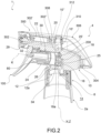
- a trigger dispensing device comprising a bottle 2 for containing a liquid product to be dispensed, and a trigger dispensing head 4 applied to a neck 2a of the bottle have been collectively referred to as 1.
- the neck 2a has a neck axis X.
- the head 4 is applicable to the bottle 2 by means of a ferrule system comprising a threaded ferrule 6 which may be screwed to the neck 2a or, according to a variant embodiment, by means of a bayonet system (not shown), preferably equipped with an anti-removal ridge.
- the head 4 comprises a frame 10, preferably made in one piece of plastic material, for example by injection molding, adapted to support the components of the head 4.
- the frame 10 comprises an attachment portion 12 provided with a main opening 12a having an attachment axis Z; when the head 4 is applied to the neck 2a, the main opening 12a is in communication with the compartment inside the neck 2a, and the attachment axis Z is coincident with the neck axis X.
- the head 4 further comprises a circular cylindrical shaped cylinder chamber 14 having a chamber axis K orthogonal to the attachment axis Z; preferably, the cylinder chamber 14 is formed in the frame 10.
- the head 4 further comprises a suction duct that connects the main opening 12a with the cylinder chamber 14.
- said suction duct comprises a first suction segment 16 which, starting from the main opening 12a, extends along a first suction axis W, parallel to and preferably spaced apart from the attachment axis Z, and a second suction segment 18 which flows into the cylinder chamber 14 and extends along a second suction axis Y, parallel to the chamber axis K; for example, the second suction axis Y is coincident with the chamber axis K.
- the second suction segment 18 is delimited by a suction mouth 18a.
- the first suction segment 16 and/or the second suction segment 18 are formed in the frame 10.
- the head 4 further comprises a dispensing duct that places the cylinder chamber 14 in communication with the external environment.
- the dispensing duct comprises a first dispensing segment 20 which, starting from the cylinder chamber 14, extends along a first suction axis J orthogonal to the chamber axis K, and a second dispensing segment 22 which opens to the external environment and extends along a second dispensing axis Q parallel to the chamber axis K.
- the first dispensing segment 20 and/or the second dispensing segment 22 are formed in the frame 10.
- the head 4 further comprises a nozzle 29, applied to the free end of the second dispensing segment 22, preferably rotatable at least between a dispensing position, wherein the second dispensing segment 22 is in communication with the external environment, and a closed position, wherein the fluid communication between the second dispensing segment 22 and the external environment is prevented.
- the cylinder chamber 14 is annularly delimited by a cylinder wall 24, having an inner surface 24b, and on the bottom by a bottom wall 25, from which the suction mouth 18a of the suction duct, and in particular the second suction segment 18, protrudes. Further, a valve compartment 25' is defined between the sleeve 30, the cylinder wall 24, and the bottom wall 25, which will be discussed below.
- the head 4 further comprises a sleeve 30, inserted into the cylinder chamber 14, for example axially rotatable with the chamber axis K and preferably constrained with respect to an axial translation.
- the sleeve 30 comprises a cylindrical sleeve wall 32 that defines a head opening 33 of the sleeve 30, delimited by a sleeve edge 33a; the sleeve wall 32 further has an outer surface 32a and an inner surface 32b.
- the sleeve 30 further comprises a bottom wall 34 orthogonal to the chamber axis K and an annular end wall 36 defining a bottom opening 38 of the sleeve 30.
- the annular end wall 36 is radially lowered with respect of the sleeve wall 32.
- the end wall 36 has a smaller diameter than the sleeve wall 32.
- valve compartment 25' has an annular shape extending radially externally about the end wall 36.
- the sleeve 30 On the outer surface 32a, the sleeve 30 has a first sealing region 40, delimited by first sealing ridges, e.g., first circumferential sealing ridges 42a and first axial sealing ridges 42b, and a second closed sealing region 44, delimited by second sealing ridges, e.g., second circumferential sealing ridges 42c.
- first sealing ridges e.g., first circumferential sealing ridges 42a and first axial sealing ridges 42b
- second closed sealing region 44 delimited by second sealing ridges, e.g., second circumferential sealing ridges 42c.
- first circumferential sealing ridges 42a and the second circumferential sealing ridges 42c form two continuous, axially spaced circumferential sealing beads, while the first axial sealing ridges 42 form two continuous, circumferentially spaced axial sealing beads arranged between said circumferential sealing beads.
- the axial sealing ridges are arranged on the outer surface of the sleeve, while the circumferential sealing ridges are arranged on the inner surface of the cylinder wall.
- the sleeve 30 also has a secondary vent passage 50 passing through the sleeve wall 32, which opens onto the outer surface 32a within the first sealing region 40.
- the sleeve 30 further comprises at least one pin 51, preferably a pair of pins, projecting from the outer surface 32a and suitable to be accommodated in the respective slot 28 of the cylinder chamber 14.
- the sleeve 30 has at least one pocket 60, preferably a pair of pockets, having a predetermined angular extension, open on the head opening 33 of the sleeve 30 so as to be axially accessible.
- said pocket 60 forms an enlargement 62 on the sleeve edge 33a of the head opening 33.
- the sleeve 30 further comprises a maneuvering portion 70, for example comprising an element extending radially externally from the sleeve wall 32 proximal to the head opening 33.
- the suction duct flows into the sleeve 30 through the bottom opening 38; in particular, the second suction segment 18 opens into the sleeve 30, for example, in the compartment delimited by the end wall 36.
- the head 4 further comprises a piston 80, preferably insertable into the sleeve 30 through the head opening 33 and sealingly slidable within said sleeve 30.
- the piston 88 is made in one piece of plastic material, obtained for example by injection molding.
- the preferably hollow piston 80 comprises an annular piston wall 82 extending along a piston axis P between a front end 84 and a rear end 86.
- the piston 80 further comprises a piston bottom 86 at the front end 84 and at least one circumferential piston seal 88 protruding externally from the piston wall 82.
- the piston 80 has a piston-coupling portion 90 for coupling to a trigger of the head 4, provided, for example, with holes 92.
- the piston 80 further comprises at least one abutment 94, preferably a pair of abutments, projecting radially externally from the piston wall 82, preferably in the proximity of the rear end 86.
- the sleeve 30 When the head 4 is assembled, the sleeve 30 is inserted into the cylinder chamber 14 so that the sleeve edge 33a remains outside the cylinder chamber 14 and abuts against the edge of the cylinder wall 24; the maneuvering portion 70 also remains outside.
- the pin 51 of the sleeve 30 is accommodated slidably in the slot 28.
- the sealing ridges 42a, 42b, 42c on the outer surface 32a of the sleeve 30 form a seal with the inner surface 24b of the cylinder wall 24.
- the piston 80 is in turn inserted within the sleeve 30; within the sleeve 30, the piston seal 88 delimits a pressure chamber 30a, on the side where the suction duct opens.
- the piston is sealingly slidable in the cylinder chamber, so that the piston seal is in sealed contact and slidable on the inner surface of the piston chamber.
- the head 4 further comprises a trigger 100, comprising a lever actuation portion 102 suitable for positioning the user's fingers for actuating the head 4, and a trigger engagement portion 104 for connecting with the piston 80.
- the trigger 100 is hinged to the piston 80, such as by engagement of the trigger engagement portion 104 with the piston engagement portion 90 of the piston 80.
- the head 4 further comprises elastic return means suitable for permanently acting on the piston 80, either directly or indirectly, to bring it toward an initial position which will be discussed hereinafter.
- said return means comprise at least one flexible element 110, preferably a pair of flexible elements, made in one piece with the actuation portion 102 of the trigger 100.
- the head 4 further comprises valve means suitable for regulating the flow of product from the suction duct to the pressure chamber 30a and from the pressure chamber 30a to the dispensing duct.
- Said valve means are preferably accommodated in the valve compartment 25'.
- Said valve means comprise an at least partially flexible valve element 200 made in one piece, for example, by injection molding.
- the valve element 200 comprises a tubular portion 202 comprising an annular valve wall 204 extending along a valve axis V, between a rear end 206 defining a rear opening 208, and a front end 210.
- the valve element 200 further comprises a flexible flap 212 connected in a cantilevered manner to the front end 210 of the valve wall 204, projecting radially internally.
- the flap 212 has, from the side facing the rear opening 208, a shutter portion 214, for example flat or hemispherical or truncated-cone shape.
- the valve element 200 further comprises an annular membrane 216 that extends radially externally from the tubular portion 202.
- the membrane 216 is, for example, flat or, according to further variants (not shown), concave on the part facing the front end 210 of the tubular portion 202 or convex on the part facing the front end 210 of the tubular portion 202.
- the membrane 216 extends radially beyond the end wall 36.
- the valve element 200 further comprises a support portion 218 composed of an annular support wall 220 that connects to and surrounds the membrane 216.
- the support wall 220 has a flared shape towards the front end 210 of the tubular portion 202 and, on the part facing the rear end 206, a wavy valve base 222 that forms a support for the valve element.
- the valve element 200 is located in the cylinder chamber 14, against the bottom wall 25, against which the valve base 222 is placed; the support wall 220, on the other hand, is in contact with the cylinder wall 24 and creates a seal against product leakage.
- the tubular portion 212 is threaded onto the suction duct, and in particular onto the second suction segment 18, and the flap 212 forms a flexible shutter for said suction duct.
- the suction mouth 18a of the suction duct and the flexible flap 212 form suitable suction valve means for allowing product to pass from the suction duct to the pressure chamber 30a in a suction phase and preventing product from passing from the pressure chamber 30a to the suction duct in a dispensing phase.
- the membrane 216 cooperates with the sleeve 30, and in particular closes the bottom opening 38 of the pressure chamber 30a and abuts against the end wall 36.
- the end wall 36 and the membrane 216 form pre-compression valve means suitable to allow product to pass from the pressure chamber 30a to the dispensing duct only when the pressure in the pressure chamber 30a exceeds a predetermined threshold value.
- Said pre-compression valves are also suitable for preventing the product from passing from the dispensing duct to the pressure chamber 30a during a suction phase.
- valve element 200 cooperating with the suction mouth 18a of the suction duct and the end wall 36 of the sleeve thus integrates both the suction valve means and the pre-compression valve means into a single component.
- the head 4 is applied to the bottle 2, so that the suction duct is in communication with the compartment inside the bottle, via the main opening 12a.
- the sleeve 30 is in an angular locked position whereby the sleeve edge 33a forms an obstacle to the axial translation of the abutment 94 of the piston 80, whereby, while actuating the trigger 100, the piston 80 is prevented from completing a stroke that actuates dispensing.
- the maneuvering portion 70 and the pin 51 of the sleeve 30 are in their respective angular locked positions.
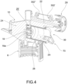
- the main vent passage 26 is sealed from the outside environment, thus preventing the product from escaping to the outside in the event of the device tipping over.
- the main vent passage 26 opens into the second sealing region 44 of the outer surface 32a of the sleeve 30, which, cooperating with the inner side surface 24b of the cylinder wall 24, forms a sealed closed space ( Fig. 4 ).
- the head 4 reaches an initial release configuration ( Fig. 5 ), wherein the pocket 60 of the sleeve 30 is axially aligned with the abutment 94 of the piston 80, so that, upon actuating the trigger 100, the piston 80 may make an actuation stroke of the head that allows product to be dispensed.
- the maneuvering portion 70 and the pin 51 of the sleeve 30 are in the respective angular release position.
- the main vent passage 26 is open to the external environment, thus allowing air to be drawn in from the outside into the internal compartment of the bottle during the suction phase.
- the main vent passage 26 flows into the first sealing region 40 of the outer surface 32a of the sleeve 30, which, cooperating with the inner side surface 24b of the cylinder wall 24, forms a delimited space which, via the secondary vent passage 50, communicates with the inner surface 32b of the sleeve 30, which is in communication with the external environment during the suction phase ( Fig. 6 ).
- the sleeve 30 is rotatable by the user between an angular working position, wherein the main vent passage 26 is in fluid communication with the secondary vent passage 50, and an angular rest position, wherein the main vent passage 26 is fluidically separated from the secondary vent passage 50.
- the main vent passage 26 in the angular rest position, is fluidically separated from the secondary vent passage 50 by said sealing ridges 42a, 42b, 42c, arranged between the inner surface 24b of the cylinder wall 24 and the outer surface 32a of the sleeve wall 32.
- the trigger 100 and the piston 80 are in a respective initial rest position, and the pre-compression valve means and the suction valve means are in a respective closed configuration.
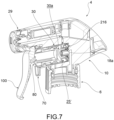
- the pre-compression valve means pass to an open configuration wherein they allow the product to pass from the pressure chamber 30a to the dispensing duct ( Fig. 7 ).
- the membrane 216 separates from the end wall 36 of the sleeve 30 and allows the product to pass to the dispensing duct, allowing it to be dispensed externally through the nozzle 29 (dispensing phase).
- the suction valve means remain in the closed configuration.
- the trigger 100 and piston 80 are in the end position ( Fig. 8 ) and the dispensing phase is complete, the trigger 100 is released and the elastic return devices operate to return the piston 80 and the trigger 100 to their initial rest position.
- the flap 216 flexes and separates from the suction mouth 18a of the suction duct, allowing the product to pass from the suction duct into the pressure chamber 30a (suction phase).
- the internal compartment of the bottle is in communication with the external environment through the secondary vent passage 50, the first sealing region 40, and the main vent passage 26.
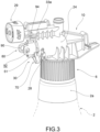
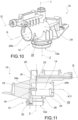
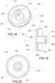
- the head 4 comprises a shell 300 attached to the frame 10 to cover it.
- the shell 300 is applied to the frame 10 by at least one snap coupling.
- first snap coupling 302 arranged in an upper region of the frame 10, such as above the second dispensing segment 22, and a second snap coupling 304, arranged in a lower region of the frame, for example below the bottom wall 25 of the cylinder chamber 14.
- the at least one snap coupling comprises a pair of flexible hooks 302', 302" that work in an opposing manner.
- an upper surface 306 of the shell 300 comprises a flat region 308.
- said region allows any weight on the device to be better supported, for example during storage in the warehouse, avoiding the detachment of the shell from the frame.
- the frame 10 also has an extension or inner duct 10' of the first dispensing segment 20 along said first suction axis J.
- the extension 10' is itself open to the outside by means of a duct opening 10", in order to allow, during the molding of the frame, the introduction of a core for forming the first dispensing segment 20.
- the shell 300 comprises a cap 310, protruding internally, suitable for closing off access to the outside of the extension 10'.
- the cap 310 is connected to the remaining portion of the shell 300 via a plurality of breakable septa 312.
- a plurality of breakable septa 312 In the event of strong impacts, such as to cause even temporary deformation of the shell 300 or even disassembly, at least some of said septa 312 will encounter breakage, so that the cap 310 is at least partially released from the remaining portion of the shell 300 and remains to close the extension 10'.
- the shell is devoid of the cap, and the head comprises a separate cap, applied to the extension to close it.
- the trigger dispensing head 4 comprises a frame 10 for supporting components and a shell 300 applied to the frame 10 for covering said components, wherein said frame 10 has an inner duct 10' opening to the outside via a duct opening 10" and said shell 300 comprises internally a cap 310 made in one piece with the remaining portion of the shell, wherein the cap 310 closes access to the outside of the inner duct 10' and said cap 310 is joined to the remaining part of the shell via at least one breakable septum 312.
- this allows for the construction of a trigger dispensing head that may absorb shocks due to less than optimal transport conditions. In effect, if such shocks tend to deform or disassemble the shell, the septa will break and the internal duct will remain closed, avoiding unwanted product spillage.
- the above-described dispensing head satisfies the needs of the industry and overcomes the aforementioned drawbacks, in that the valve element integrates suction and pre-compression valve means and, at the same time, facilitates the manufacturing of the component and the assembly of the head.
Landscapes
- Engineering & Computer Science (AREA)
- General Engineering & Computer Science (AREA)
- Chemical & Material Sciences (AREA)
- Combustion & Propulsion (AREA)
- Mechanical Engineering (AREA)
- Closures For Containers (AREA)
- Containers And Packaging Bodies Having A Special Means To Remove Contents (AREA)
- Nozzles (AREA)
Claims (9)
- Abzugs-Abgabekopf (4), der auf eine Flasche (2) einer Abzugs-Abgabevorrichtung (1) zur Abgabe eines Produkts aufbringbar ist, umfassend:- eine Zylinderkammer (14), die ringförmig durch eine Zylinderwand (24), die eine Innenfläche bzw. -oberfläche (24b) aufweist, und durch eine Bodenwand (25) am Boden begrenzt ist;- einen Kolben (80), der manuell betätigbar ist, um sich entlang einer axialen Richtung zu verschieben;- eine Druckkammer (30a), auf die der Kolben (80) einwirkt;- eine Hülse (30), die zumindest teilweise in der Zylinderkammer (14) untergebracht ist und eine ringförmige Endwand (36) umfasst, die eine Bodenöffnung (38) der Hülse (30) definiert, wobei die Hülse (30), die Zylinderwand (24) und die Bodenwand (25) einen Ventilraum (25') definieren;- einen Saugkanal, der angepasst ist, einen Innenraum der Flasche mit der Druckkammer (30) in Kommunikation zu bringen, und eine Saugmündung (18a) umfasst, die axial von der Bodenwand (25) vorsteht;- einen Abgabekanal, der angepasst ist, die Druckkammer (30a) mit der äußeren Umgebung in Kommunikation zu bringen;- Ventilmittel zum Einstellen der Produktströmung von dem Saugkanal zu der Druckkammer (30a) während eines Saugschritts und von der Druckkammer zu dem Abgabekanal während eines Abgabeschritts, umfassend ein einstückiges Ventilelement (200) umfasst, das in der Ventilkammer (25') untergebracht ist, umfassend:a) einen rohrförmigen Abschnitt (202), der aus einer ringförmigen Ventilwand (204) besteht, die sich entlang einer Ventilachse (V) zwischen einem hinteren Ende (206), das eine hintere Öffnung (208) definiert, und einem vorderen Ende (210), das eine vordere Öffnung (209) definiert, erstreckt, wobei die Ventilwand (204) an der Saugmündung (18a) gepasst ist;b) eine flexible Klappe (212), die freitragend mit dem vorderen Ende (210) der Ventilwand (204) verbunden ist, radial nach innen vorsteht und auf der der hinteren Öffnung (208) zugewandten Seite mit einem Verschlussabschnitt (214) versehen ist, der angepasst ist, eine Dichtung mit der Saugmündung (18a) zu bilden, um Ventilmittel zu erhalten;c) eine ringförmige Membran (216), die sich von der Ventilwand (204) radial nach außen erstreckt und angepasst ist, an der ringförmigen Endwand (36) der Hülse (30) anzuliegen und somit eine Dichtung mit der Bodenöffnung (38) zu bilden, um Vorkompressionsventilmittel zu erhalten.
- Abzugs-Abgabekopf nach Anspruch 1, wobei die Saugmündung (18a) in dem durch die ringförmige Endwand (36) abgegrenzten Raum untergebracht ist.
- Abzugs-Abgabekopf nach Anspruch 1 oder 2, wobei der Verschlussabschnitt (214) eine flache oder halbkugelförmige oder kugelförmige Kuppel- oder Kegelstumpfform aufweist.
- Abzugs-Abgabekopf nach Anspruch 1 oder 2 oder 3, wobei in einer Ruhekonfiguration die Membran (216) flach oder konkav auf der dem vorderen Ende (210) zugewandten Seite oder konvex auf der dem vorderen Ende (210) zugewandten Seite ist.
- Abzugs-Abgabekopf nach einem der vorhergehenden Ansprüche, wobei das Ventilelement (200) ferner einen Trag- bzw. Stützabschnitt (218) umfasst, der aus einer ringförmigen Trag- bzw. Stützwand (220) besteht, die mit der Membran (216) verbunden ist und diese umgibt, wobei die Stützwand (220) von außen mit der Zylinderwand (24) in Kontakt steht und mit dieser eine Dichtung gegen das Ausströmen des Produkts bildet.
- Abzugs-Abgabekopf nach Anspruch 5, wobei die Stützwand (220) zu dem vorderen Ende (210) hin eine aufgeweitete Form aufweist.
- Abzugs-Abgabekopf nach Anspruch 5 oder 6, wobei die Stützwand (220) eine gewellte Ventilbasis (222) aufweist, die eine Auflage für das Ventilelement (200) bildet.
- Abzugs-Abgabekopf nach einem der vorhergehenden Ansprüche, wobei der Kolben (80) innerhalb der Hülse (30) verschiebbar ist und mit dieser die Druckkammer (30a) bildet.
- Abzugs-Abgabekopf (4), der auf eine Flasche (2) einer Abzugs-Abgabevorrichtung (1) zur Abgabe eines Produkts aufbringbar ist, umfassend einen Rahmen (10) zum Tragen von Komponenten und eine Hülle (300), die auf den Rahmen (10) aufgebracht ist, um die Komponenten abzudecken, wobei der Rahmen (10) einen inneren Kanal (10`) aufweist, der durch einen Kanalanschluss (10") nach außen gerichtet ist, und wobei die Hülle (300) im Inneren eine Kappe (310) umfasst, die einstückig mit dem verbleibenden Teil der Hülle hergestellt ist, wobei die Kappe (310) den Zugang zu dem Äußeren des inneren Kanals (10') verschließt und die Kappe (310) mit dem verbleibenden Teil der Hülle mittels mindestens einer brechbaren Scheidewand (312) verbunden ist.
Applications Claiming Priority (2)
| Application Number | Priority Date | Filing Date | Title |
|---|---|---|---|
| IT102021000003749A IT202100003749A1 (it) | 2021-02-18 | 2021-02-18 | Dispositivo di erogazione a grilletto con mezzi valvolari |
| PCT/IB2022/051423 WO2022175867A1 (en) | 2021-02-18 | 2022-02-17 | Trigger dispensing device with valve means |
Publications (2)
| Publication Number | Publication Date |
|---|---|
| EP4294579A1 EP4294579A1 (de) | 2023-12-27 |
| EP4294579B1 true EP4294579B1 (de) | 2025-01-01 |
Family
ID=75769811
Family Applications (1)
| Application Number | Title | Priority Date | Filing Date |
|---|---|---|---|
| EP22707848.2A Active EP4294579B1 (de) | 2021-02-18 | 2022-02-17 | Abzugshebelabgabevorrichtung mit ventilmitteln |
Country Status (8)
| Country | Link |
|---|---|
| US (1) | US20240075488A1 (de) |
| EP (1) | EP4294579B1 (de) |
| CN (1) | CN116917049A (de) |
| ES (1) | ES3010692T3 (de) |
| IT (1) | IT202100003749A1 (de) |
| MX (1) | MX2023008480A (de) |
| WO (1) | WO2022175867A1 (de) |
| ZA (1) | ZA202307062B (de) |
Families Citing this family (3)
| Publication number | Priority date | Publication date | Assignee | Title |
|---|---|---|---|---|
| IT202100027218A1 (it) | 2021-10-22 | 2023-04-22 | Guala Dispensing Spa | Testa di erogazione a grilletto con camera pistone ridotta |
| IT202200016053A1 (it) * | 2022-07-28 | 2024-01-28 | Guala Dispensing Spa | Testa di erogazione a grilletto |
| IT202200021234A1 (it) * | 2022-10-14 | 2024-04-14 | Guala Dispensing Spa | Telaio e guscio per un dispositivo di erogazione a grilletto |
Family Cites Families (9)
| Publication number | Priority date | Publication date | Assignee | Title |
|---|---|---|---|---|
| US4971227A (en) * | 1989-06-02 | 1990-11-20 | Calmar, Inc. | Manually actuated dispensing pump sprayer having a removable nozzle locking element |
| US6869027B2 (en) * | 1994-12-05 | 2005-03-22 | Continental Afa Dispensing Company | Dual component and dual valve trigger sprayer which mixes components in discharge passage |
| JPH10174913A (ja) * | 1996-12-18 | 1998-06-30 | Yoshino Kogyosho Co Ltd | トリガー式噴出器 |
| JP4392188B2 (ja) * | 2003-04-18 | 2009-12-24 | 花王株式会社 | トリガー式液体噴出器 |
| ITBS20120116A1 (it) | 2012-07-24 | 2014-01-25 | Guala Dispensing Spa | Dispositivo di erogazione a grilletto |
| US9307871B2 (en) * | 2012-08-30 | 2016-04-12 | Gojo Industries, Inc. | Horizontal pumps, refill units and foam dispensers |
| JP6308809B2 (ja) * | 2013-08-30 | 2018-04-11 | 株式会社吉野工業所 | トリガー式液体噴出器 |
| US10139219B2 (en) * | 2015-12-17 | 2018-11-27 | ASTRODESIGN, Inc. | Optical distance measuring apparatus |
| CN121696042A (zh) * | 2016-06-21 | 2026-03-20 | 斯勒冈分配系统公司 | 触发式喷洒器 |
-
2021
- 2021-02-18 IT IT102021000003749A patent/IT202100003749A1/it unknown
-
2022
- 2022-02-17 EP EP22707848.2A patent/EP4294579B1/de active Active
- 2022-02-17 CN CN202280015701.5A patent/CN116917049A/zh active Pending
- 2022-02-17 WO PCT/IB2022/051423 patent/WO2022175867A1/en not_active Ceased
- 2022-02-17 US US18/261,320 patent/US20240075488A1/en active Pending
- 2022-02-17 MX MX2023008480A patent/MX2023008480A/es unknown
- 2022-02-17 ES ES22707848T patent/ES3010692T3/es active Active
-
2023
- 2023-07-13 ZA ZA2023/07062A patent/ZA202307062B/en unknown
Also Published As
| Publication number | Publication date |
|---|---|
| CN116917049A (zh) | 2023-10-20 |
| IT202100003749A1 (it) | 2022-08-18 |
| US20240075488A1 (en) | 2024-03-07 |
| ES3010692T3 (en) | 2025-04-04 |
| ZA202307062B (en) | 2025-04-30 |
| EP4294579A1 (de) | 2023-12-27 |
| WO2022175867A1 (en) | 2022-08-25 |
| MX2023008480A (es) | 2023-07-28 |
Similar Documents
| Publication | Publication Date | Title |
|---|---|---|
| EP4294579B1 (de) | Abzugshebelabgabevorrichtung mit ventilmitteln | |
| EP2874756B1 (de) | Spender mit auslöser | |
| EP4363124B1 (de) | Triggerspenderkopf mit mitteln zur vermeidung von leckagen | |
| EP4575276A2 (de) | Spendervorrichtung mit auslöser zur vermeidung des produktverlustes | |
| EP2849892B1 (de) | Spendervorrichtung mit auslöser | |
| EP3466546B1 (de) | Hebelbetätigter zerstäuber | |
| EP2648853B1 (de) | Spendervorrichtung mit auslöser und zuführventil | |
| IT202200021228A1 (it) | Dispositivo di erogazione a grilletto | |
| US12544778B2 (en) | Trigger dispensing head with reduced piston chamber | |
| US20260061443A1 (en) | Trigger dispensing device for upside down operation | |
| US12337339B2 (en) | Trigger dispensing device | |
| RU2847581C1 (ru) | Триггерное дозирующее устройство с клапанным средством | |
| IT202300010968A1 (it) | Dispositivo di erogazione a grilletto | |
| MXPA00005009A (en) | Sprayer nozzle with closing membrane |
Legal Events
| Date | Code | Title | Description |
|---|---|---|---|
| STAA | Information on the status of an ep patent application or granted ep patent |
Free format text: STATUS: UNKNOWN |
|
| STAA | Information on the status of an ep patent application or granted ep patent |
Free format text: STATUS: THE INTERNATIONAL PUBLICATION HAS BEEN MADE |
|
| PUAI | Public reference made under article 153(3) epc to a published international application that has entered the european phase |
Free format text: ORIGINAL CODE: 0009012 |
|
| STAA | Information on the status of an ep patent application or granted ep patent |
Free format text: STATUS: REQUEST FOR EXAMINATION WAS MADE |
|
| 17P | Request for examination filed |
Effective date: 20230706 |
|
| AK | Designated contracting states |
Kind code of ref document: A1 Designated state(s): AL AT BE BG CH CY CZ DE DK EE ES FI FR GB GR HR HU IE IS IT LI LT LU LV MC MK MT NL NO PL PT RO RS SE SI SK SM TR |
|
| DAV | Request for validation of the european patent (deleted) | ||
| DAX | Request for extension of the european patent (deleted) | ||
| REG | Reference to a national code |
Ref country code: DE Ref legal event code: R079 Free format text: PREVIOUS MAIN CLASS: B05B0011000000 Ipc: B05B0011100000 Ref document number: 602022009368 Country of ref document: DE |
|
| GRAP | Despatch of communication of intention to grant a patent |
Free format text: ORIGINAL CODE: EPIDOSNIGR1 |
|
| RIC1 | Information provided on ipc code assigned before grant |
Ipc: F16J 1/00 20060101ALI20240904BHEP Ipc: B05B 15/14 20180101ALI20240904BHEP Ipc: B05B 11/10 20230101AFI20240904BHEP |
|
| STAA | Information on the status of an ep patent application or granted ep patent |
Free format text: STATUS: GRANT OF PATENT IS INTENDED |
|
| INTG | Intention to grant announced |
Effective date: 20241010 |
|
| GRAS | Grant fee paid |
Free format text: ORIGINAL CODE: EPIDOSNIGR3 |
|
| GRAA | (expected) grant |
Free format text: ORIGINAL CODE: 0009210 |
|
| STAA | Information on the status of an ep patent application or granted ep patent |
Free format text: STATUS: THE PATENT HAS BEEN GRANTED |
|
| AK | Designated contracting states |
Kind code of ref document: B1 Designated state(s): AL AT BE BG CH CY CZ DE DK EE ES FI FR GB GR HR HU IE IS IT LI LT LU LV MC MK MT NL NO PL PT RO RS SE SI SK SM TR |
|
| REG | Reference to a national code |
Ref country code: GB Ref legal event code: FG4D |
|
| P01 | Opt-out of the competence of the unified patent court (upc) registered |
Free format text: CASE NUMBER: APP_64575/2024 Effective date: 20241205 |
|
| REG | Reference to a national code |
Ref country code: CH Ref legal event code: EP |
|
| REG | Reference to a national code |
Ref country code: DE Ref legal event code: R096 Ref document number: 602022009368 Country of ref document: DE |
|
| REG | Reference to a national code |
Ref country code: IE Ref legal event code: FG4D |
|
| REG | Reference to a national code |
Ref country code: ES Ref legal event code: FG2A Ref document number: 3010692 Country of ref document: ES Kind code of ref document: T3 Effective date: 20250404 |
|
| PGFP | Annual fee paid to national office [announced via postgrant information from national office to epo] |
Ref country code: AT Payment date: 20250417 Year of fee payment: 4 |
|
| REG | Reference to a national code |
Ref country code: LT Ref legal event code: MG9D |
|
| REG | Reference to a national code |
Ref country code: NL Ref legal event code: MP Effective date: 20250101 |
|
| REG | Reference to a national code |
Ref country code: AT Ref legal event code: MK05 Ref document number: 1755695 Country of ref document: AT Kind code of ref document: T Effective date: 20250101 |
|
| PG25 | Lapsed in a contracting state [announced via postgrant information from national office to epo] |
Ref country code: NL Free format text: LAPSE BECAUSE OF FAILURE TO SUBMIT A TRANSLATION OF THE DESCRIPTION OR TO PAY THE FEE WITHIN THE PRESCRIBED TIME-LIMIT Effective date: 20250101 |
|
| PG25 | Lapsed in a contracting state [announced via postgrant information from national office to epo] |
Ref country code: FI Free format text: LAPSE BECAUSE OF FAILURE TO SUBMIT A TRANSLATION OF THE DESCRIPTION OR TO PAY THE FEE WITHIN THE PRESCRIBED TIME-LIMIT Effective date: 20250101 |
|
| PG25 | Lapsed in a contracting state [announced via postgrant information from national office to epo] |
Ref country code: PL Free format text: LAPSE BECAUSE OF FAILURE TO SUBMIT A TRANSLATION OF THE DESCRIPTION OR TO PAY THE FEE WITHIN THE PRESCRIBED TIME-LIMIT Effective date: 20250101 |
|
| PG25 | Lapsed in a contracting state [announced via postgrant information from national office to epo] |
Ref country code: IS Free format text: LAPSE BECAUSE OF FAILURE TO SUBMIT A TRANSLATION OF THE DESCRIPTION OR TO PAY THE FEE WITHIN THE PRESCRIBED TIME-LIMIT Effective date: 20250501 Ref country code: NO Free format text: LAPSE BECAUSE OF FAILURE TO SUBMIT A TRANSLATION OF THE DESCRIPTION OR TO PAY THE FEE WITHIN THE PRESCRIBED TIME-LIMIT Effective date: 20250401 |
|
| PG25 | Lapsed in a contracting state [announced via postgrant information from national office to epo] |
Ref country code: HR Free format text: LAPSE BECAUSE OF FAILURE TO SUBMIT A TRANSLATION OF THE DESCRIPTION OR TO PAY THE FEE WITHIN THE PRESCRIBED TIME-LIMIT Effective date: 20250101 |
|
| PG25 | Lapsed in a contracting state [announced via postgrant information from national office to epo] |
Ref country code: LV Free format text: LAPSE BECAUSE OF FAILURE TO SUBMIT A TRANSLATION OF THE DESCRIPTION OR TO PAY THE FEE WITHIN THE PRESCRIBED TIME-LIMIT Effective date: 20250101 Ref country code: PT Free format text: LAPSE BECAUSE OF FAILURE TO SUBMIT A TRANSLATION OF THE DESCRIPTION OR TO PAY THE FEE WITHIN THE PRESCRIBED TIME-LIMIT Effective date: 20250502 |
|
| PG25 | Lapsed in a contracting state [announced via postgrant information from national office to epo] |
Ref country code: BG Free format text: LAPSE BECAUSE OF FAILURE TO SUBMIT A TRANSLATION OF THE DESCRIPTION OR TO PAY THE FEE WITHIN THE PRESCRIBED TIME-LIMIT Effective date: 20250101 Ref country code: GR Free format text: LAPSE BECAUSE OF FAILURE TO SUBMIT A TRANSLATION OF THE DESCRIPTION OR TO PAY THE FEE WITHIN THE PRESCRIBED TIME-LIMIT Effective date: 20250402 |
|
| PG25 | Lapsed in a contracting state [announced via postgrant information from national office to epo] |
Ref country code: AT Free format text: LAPSE BECAUSE OF FAILURE TO SUBMIT A TRANSLATION OF THE DESCRIPTION OR TO PAY THE FEE WITHIN THE PRESCRIBED TIME-LIMIT Effective date: 20250101 |
|
| PG25 | Lapsed in a contracting state [announced via postgrant information from national office to epo] |
Ref country code: CZ Free format text: LAPSE BECAUSE OF FAILURE TO SUBMIT A TRANSLATION OF THE DESCRIPTION OR TO PAY THE FEE WITHIN THE PRESCRIBED TIME-LIMIT Effective date: 20250101 |
|
| PG25 | Lapsed in a contracting state [announced via postgrant information from national office to epo] |
Ref country code: SE Free format text: LAPSE BECAUSE OF FAILURE TO SUBMIT A TRANSLATION OF THE DESCRIPTION OR TO PAY THE FEE WITHIN THE PRESCRIBED TIME-LIMIT Effective date: 20250101 |
|
| REG | Reference to a national code |
Ref country code: CH Ref legal event code: PL |
|
| REG | Reference to a national code |
Ref country code: DE Ref legal event code: R097 Ref document number: 602022009368 Country of ref document: DE |
|
| PG25 | Lapsed in a contracting state [announced via postgrant information from national office to epo] |
Ref country code: SM Free format text: LAPSE BECAUSE OF FAILURE TO SUBMIT A TRANSLATION OF THE DESCRIPTION OR TO PAY THE FEE WITHIN THE PRESCRIBED TIME-LIMIT Effective date: 20250101 |
|
| PG25 | Lapsed in a contracting state [announced via postgrant information from national office to epo] |
Ref country code: DK Free format text: LAPSE BECAUSE OF FAILURE TO SUBMIT A TRANSLATION OF THE DESCRIPTION OR TO PAY THE FEE WITHIN THE PRESCRIBED TIME-LIMIT Effective date: 20250101 |
|
| PG25 | Lapsed in a contracting state [announced via postgrant information from national office to epo] |
Ref country code: MC Free format text: LAPSE BECAUSE OF FAILURE TO SUBMIT A TRANSLATION OF THE DESCRIPTION OR TO PAY THE FEE WITHIN THE PRESCRIBED TIME-LIMIT Effective date: 20250101 |
|
| PG25 | Lapsed in a contracting state [announced via postgrant information from national office to epo] |
Ref country code: LU Free format text: LAPSE BECAUSE OF NON-PAYMENT OF DUE FEES Effective date: 20250217 |
|
| PG25 | Lapsed in a contracting state [announced via postgrant information from national office to epo] |
Ref country code: CH Free format text: LAPSE BECAUSE OF NON-PAYMENT OF DUE FEES Effective date: 20250228 |
|
| PG25 | Lapsed in a contracting state [announced via postgrant information from national office to epo] |
Ref country code: EE Free format text: LAPSE BECAUSE OF FAILURE TO SUBMIT A TRANSLATION OF THE DESCRIPTION OR TO PAY THE FEE WITHIN THE PRESCRIBED TIME-LIMIT Effective date: 20250101 |
|
| PG25 | Lapsed in a contracting state [announced via postgrant information from national office to epo] |
Ref country code: RO Free format text: LAPSE BECAUSE OF FAILURE TO SUBMIT A TRANSLATION OF THE DESCRIPTION OR TO PAY THE FEE WITHIN THE PRESCRIBED TIME-LIMIT Effective date: 20250101 |
|
| PG25 | Lapsed in a contracting state [announced via postgrant information from national office to epo] |
Ref country code: SK Free format text: LAPSE BECAUSE OF FAILURE TO SUBMIT A TRANSLATION OF THE DESCRIPTION OR TO PAY THE FEE WITHIN THE PRESCRIBED TIME-LIMIT Effective date: 20250101 |
|
| PLBE | No opposition filed within time limit |
Free format text: ORIGINAL CODE: 0009261 |
|
| STAA | Information on the status of an ep patent application or granted ep patent |
Free format text: STATUS: NO OPPOSITION FILED WITHIN TIME LIMIT |
|
| REG | Reference to a national code |
Ref country code: BE Ref legal event code: MM Effective date: 20250228 |
|
| 26N | No opposition filed |
Effective date: 20251002 |
|
| PG25 | Lapsed in a contracting state [announced via postgrant information from national office to epo] |
Ref country code: BE Free format text: LAPSE BECAUSE OF NON-PAYMENT OF DUE FEES Effective date: 20250228 |
|
| PG25 | Lapsed in a contracting state [announced via postgrant information from national office to epo] |
Ref country code: IE Free format text: LAPSE BECAUSE OF NON-PAYMENT OF DUE FEES Effective date: 20250217 |
|
| PGFP | Annual fee paid to national office [announced via postgrant information from national office to epo] |
Ref country code: GB Payment date: 20260220 Year of fee payment: 5 |
|
| PGFP | Annual fee paid to national office [announced via postgrant information from national office to epo] |
Ref country code: ES Payment date: 20260302 Year of fee payment: 5 |
|
| PGFP | Annual fee paid to national office [announced via postgrant information from national office to epo] |
Ref country code: DE Payment date: 20260223 Year of fee payment: 5 |
|
| PGFP | Annual fee paid to national office [announced via postgrant information from national office to epo] |
Ref country code: IT Payment date: 20260123 Year of fee payment: 5 |
|
| PGFP | Annual fee paid to national office [announced via postgrant information from national office to epo] |
Ref country code: FR Payment date: 20260130 Year of fee payment: 5 |