EP4293258B1 - Ventilaktuator - Google Patents
Ventilaktuator Download PDFInfo
- Publication number
- EP4293258B1 EP4293258B1 EP23174711.4A EP23174711A EP4293258B1 EP 4293258 B1 EP4293258 B1 EP 4293258B1 EP 23174711 A EP23174711 A EP 23174711A EP 4293258 B1 EP4293258 B1 EP 4293258B1
- Authority
- EP
- European Patent Office
- Prior art keywords
- gear
- coupled
- flange
- valve actuator
- valve
- Prior art date
- Legal status (The legal status is an assumption and is not a legal conclusion. Google has not performed a legal analysis and makes no representation as to the accuracy of the status listed.)
- Active
Links
Images


Classifications
-
- F—MECHANICAL ENGINEERING; LIGHTING; HEATING; WEAPONS; BLASTING
- F16—ENGINEERING ELEMENTS AND UNITS; GENERAL MEASURES FOR PRODUCING AND MAINTAINING EFFECTIVE FUNCTIONING OF MACHINES OR INSTALLATIONS; THERMAL INSULATION IN GENERAL
- F16K—VALVES; TAPS; COCKS; ACTUATING-FLOATS; DEVICES FOR VENTING OR AERATING
- F16K31/00—Actuating devices; Operating means; Releasing devices
- F16K31/44—Mechanical actuating means
- F16K31/53—Mechanical actuating means with toothed gearing
-
- F—MECHANICAL ENGINEERING; LIGHTING; HEATING; WEAPONS; BLASTING
- F16—ENGINEERING ELEMENTS AND UNITS; GENERAL MEASURES FOR PRODUCING AND MAINTAINING EFFECTIVE FUNCTIONING OF MACHINES OR INSTALLATIONS; THERMAL INSULATION IN GENERAL
- F16H—GEARING
- F16H57/00—General details of gearing
- F16H57/02—Gearboxes; Mounting gearing therein
- F16H57/023—Mounting or installation of gears or shafts in the gearboxes, e.g. methods or means for assembly
-
- F—MECHANICAL ENGINEERING; LIGHTING; HEATING; WEAPONS; BLASTING
- F16—ENGINEERING ELEMENTS AND UNITS; GENERAL MEASURES FOR PRODUCING AND MAINTAINING EFFECTIVE FUNCTIONING OF MACHINES OR INSTALLATIONS; THERMAL INSULATION IN GENERAL
- F16K—VALVES; TAPS; COCKS; ACTUATING-FLOATS; DEVICES FOR VENTING OR AERATING
- F16K1/00—Lift valves or globe valves, i.e. cut-off apparatus with closure members having at least a component of their opening and closing motion perpendicular to the closing faces
- F16K1/32—Details
- F16K1/34—Cutting-off parts, e.g. valve members, seats
- F16K1/46—Attachment of sealing rings
-
- F—MECHANICAL ENGINEERING; LIGHTING; HEATING; WEAPONS; BLASTING
- F16—ENGINEERING ELEMENTS AND UNITS; GENERAL MEASURES FOR PRODUCING AND MAINTAINING EFFECTIVE FUNCTIONING OF MACHINES OR INSTALLATIONS; THERMAL INSULATION IN GENERAL
- F16K—VALVES; TAPS; COCKS; ACTUATING-FLOATS; DEVICES FOR VENTING OR AERATING
- F16K11/00—Multiple-way valves, e.g. mixing valves; Pipe fittings incorporating such valves
- F16K11/02—Multiple-way valves, e.g. mixing valves; Pipe fittings incorporating such valves with all movable sealing faces moving as one unit
- F16K11/08—Multiple-way valves, e.g. mixing valves; Pipe fittings incorporating such valves with all movable sealing faces moving as one unit comprising only taps or cocks
- F16K11/087—Multiple-way valves, e.g. mixing valves; Pipe fittings incorporating such valves with all movable sealing faces moving as one unit comprising only taps or cocks with spherical plug
-
- F—MECHANICAL ENGINEERING; LIGHTING; HEATING; WEAPONS; BLASTING
- F16—ENGINEERING ELEMENTS AND UNITS; GENERAL MEASURES FOR PRODUCING AND MAINTAINING EFFECTIVE FUNCTIONING OF MACHINES OR INSTALLATIONS; THERMAL INSULATION IN GENERAL
- F16K—VALVES; TAPS; COCKS; ACTUATING-FLOATS; DEVICES FOR VENTING OR AERATING
- F16K27/00—Construction of housing; Use of materials therefor
- F16K27/02—Construction of housing; Use of materials therefor of lift valves
-
- F—MECHANICAL ENGINEERING; LIGHTING; HEATING; WEAPONS; BLASTING
- F16—ENGINEERING ELEMENTS AND UNITS; GENERAL MEASURES FOR PRODUCING AND MAINTAINING EFFECTIVE FUNCTIONING OF MACHINES OR INSTALLATIONS; THERMAL INSULATION IN GENERAL
- F16K—VALVES; TAPS; COCKS; ACTUATING-FLOATS; DEVICES FOR VENTING OR AERATING
- F16K27/00—Construction of housing; Use of materials therefor
- F16K27/06—Construction of housing; Use of materials therefor of taps or cocks
- F16K27/067—Construction of housing; Use of materials therefor of taps or cocks with spherical plugs
-
- F—MECHANICAL ENGINEERING; LIGHTING; HEATING; WEAPONS; BLASTING
- F16—ENGINEERING ELEMENTS AND UNITS; GENERAL MEASURES FOR PRODUCING AND MAINTAINING EFFECTIVE FUNCTIONING OF MACHINES OR INSTALLATIONS; THERMAL INSULATION IN GENERAL
- F16K—VALVES; TAPS; COCKS; ACTUATING-FLOATS; DEVICES FOR VENTING OR AERATING
- F16K31/00—Actuating devices; Operating means; Releasing devices
- F16K31/02—Actuating devices; Operating means; Releasing devices electric; magnetic
- F16K31/04—Actuating devices; Operating means; Releasing devices electric; magnetic using a motor
- F16K31/041—Actuating devices; Operating means; Releasing devices electric; magnetic using a motor for rotating valves
- F16K31/042—Actuating devices; Operating means; Releasing devices electric; magnetic using a motor for rotating valves with electric means, e.g. for controlling the motor or a clutch between the valve and the motor
-
- F—MECHANICAL ENGINEERING; LIGHTING; HEATING; WEAPONS; BLASTING
- F16—ENGINEERING ELEMENTS AND UNITS; GENERAL MEASURES FOR PRODUCING AND MAINTAINING EFFECTIVE FUNCTIONING OF MACHINES OR INSTALLATIONS; THERMAL INSULATION IN GENERAL
- F16K—VALVES; TAPS; COCKS; ACTUATING-FLOATS; DEVICES FOR VENTING OR AERATING
- F16K31/00—Actuating devices; Operating means; Releasing devices
- F16K31/02—Actuating devices; Operating means; Releasing devices electric; magnetic
- F16K31/04—Actuating devices; Operating means; Releasing devices electric; magnetic using a motor
- F16K31/041—Actuating devices; Operating means; Releasing devices electric; magnetic using a motor for rotating valves
- F16K31/043—Actuating devices; Operating means; Releasing devices electric; magnetic using a motor for rotating valves characterised by mechanical means between the motor and the valve, e.g. lost motion means reducing backlash, clutches, brakes or return means
-
- F—MECHANICAL ENGINEERING; LIGHTING; HEATING; WEAPONS; BLASTING
- F16—ENGINEERING ELEMENTS AND UNITS; GENERAL MEASURES FOR PRODUCING AND MAINTAINING EFFECTIVE FUNCTIONING OF MACHINES OR INSTALLATIONS; THERMAL INSULATION IN GENERAL
- F16K—VALVES; TAPS; COCKS; ACTUATING-FLOATS; DEVICES FOR VENTING OR AERATING
- F16K31/00—Actuating devices; Operating means; Releasing devices
- F16K31/02—Actuating devices; Operating means; Releasing devices electric; magnetic
- F16K31/04—Actuating devices; Operating means; Releasing devices electric; magnetic using a motor
- F16K31/05—Actuating devices; Operating means; Releasing devices electric; magnetic using a motor specially adapted for operating hand-operated valves or for combined motor and hand operation
- F16K31/055—Actuating devices; Operating means; Releasing devices electric; magnetic using a motor specially adapted for operating hand-operated valves or for combined motor and hand operation for rotating valves
-
- F—MECHANICAL ENGINEERING; LIGHTING; HEATING; WEAPONS; BLASTING
- F16—ENGINEERING ELEMENTS AND UNITS; GENERAL MEASURES FOR PRODUCING AND MAINTAINING EFFECTIVE FUNCTIONING OF MACHINES OR INSTALLATIONS; THERMAL INSULATION IN GENERAL
- F16K—VALVES; TAPS; COCKS; ACTUATING-FLOATS; DEVICES FOR VENTING OR AERATING
- F16K31/00—Actuating devices; Operating means; Releasing devices
- F16K31/44—Mechanical actuating means
- F16K31/53—Mechanical actuating means with toothed gearing
- F16K31/535—Mechanical actuating means with toothed gearing for rotating valves
-
- F—MECHANICAL ENGINEERING; LIGHTING; HEATING; WEAPONS; BLASTING
- F25—REFRIGERATION OR COOLING; COMBINED HEATING AND REFRIGERATION SYSTEMS; HEAT PUMP SYSTEMS; MANUFACTURE OR STORAGE OF ICE; LIQUEFACTION SOLIDIFICATION OF GASES
- F25B—REFRIGERATION MACHINES, PLANTS OR SYSTEMS; COMBINED HEATING AND REFRIGERATION SYSTEMS; HEAT PUMP SYSTEMS
- F25B41/00—Fluid-circulation arrangements
- F25B41/20—Disposition of valves, e.g. of on-off valves or flow control valves
-
- F—MECHANICAL ENGINEERING; LIGHTING; HEATING; WEAPONS; BLASTING
- F16—ENGINEERING ELEMENTS AND UNITS; GENERAL MEASURES FOR PRODUCING AND MAINTAINING EFFECTIVE FUNCTIONING OF MACHINES OR INSTALLATIONS; THERMAL INSULATION IN GENERAL
- F16K—VALVES; TAPS; COCKS; ACTUATING-FLOATS; DEVICES FOR VENTING OR AERATING
- F16K5/00—Plug valves; Taps or cocks comprising only cut-off apparatus having at least one of the sealing faces shaped as a more or less complete surface of a solid of revolution, the opening and closing movement being predominantly rotary
- F16K5/06—Plug valves; Taps or cocks comprising only cut-off apparatus having at least one of the sealing faces shaped as a more or less complete surface of a solid of revolution, the opening and closing movement being predominantly rotary with plugs having spherical surfaces; Packings therefor
- F16K5/0663—Packings
- F16K5/0694—Spindle sealings
Definitions
- the air conditioning system is provided with a ball valve for blocking refrigerant leakage.
- the ball valve provided in an air conditioning system to block refrigerant leakage includes a ball in which a flow path is formed, a pipe into which the ball is inserted, a tap part provided in the pipe, and a stem installed in the tap part.
- the ball valve of this configuration can open and close the refrigerant by rotating the stem, and the air conditioning system used for industrial purposes is provided with a valve actuator that is operated by an electrical signal input from the outside to block and operate the ball valve.
- valve assembly equipped with a valve actuator is a model number A20-S-15-S2-SUS304 of DME Corp.
- the valve assembly of DME Corp. is manufactured by assembling a valve actuator to a specially manufactured valve having a flange shape, and the valve actuator forms an appearance by inserting an upper case into a concave-convex portion of a lower case.
- valve actuator provided in the valve assembly of DME Corp. can be assembled only to a specially manufactured valve having a flange shape, it is impossible to additionally install it on another standard type ball valve already installed in the field.
- ball valves used all over the world are manufactured in approximately 15 standards, and the tap part provided in the ball valve is manufactured in approximately three standards.
- valve actuator provided in the valve assembly of DME Corp. can only be assembled to a specially manufactured valve having a flange shape as described above, it is impossible to additionally install it on other standard type ball valves already installed in the field.
- valve actuator provided in the valve assembly of DME Corp. does not have a seal installed at the joint between the upper case and the lower case, it is difficult to block the inside of the valve actuator from the external environment.
- valve actuator provided in the valve assembly of DME Corp. has a problem in that manual operation is impossible.
- valve assembly equipped with a valve actuator is the model number AT24-20-DC24 of Valcon Corp.
- valve actuator provided in the valve assembly of Valcon Corp. forms an appearance by inserting the upper case into the concave-convex portion of the lower case.
- valve actuator provided in the valve assembly of Valcon Corp. does not have a seal installed at the joint between the upper case and the lower case. Further, in the valve actuator provided in the valve assembly of Valcon Corp. a separate mold is not installed at a portion where the wire part passes through the cover to connect the electric motor (40) provided inside the valve actuator to a power source. Thus, it is difficult to block the inside of the valve actuator from the external environment.
- US 2007/0108402 A1 discloses a sealing hub assembly for a motor actuated valve having a stem boss and a stem rotatably received in the stem boss.
- JP 2013 040636 A discloses a rotary valve with an actuator.
- CN 204 628 727 U relates to coalmining facility and discloses an electrically moving ball valve with intrinsic safety.
- the present invention is defined by independent claim 1; the dependent claims describe embodiments of the present invention.
- An object of the present disclosure is to provide a valve actuator capable of solving at least one of the above problems.
- Still another object of the present disclosure is to provide a valve actuator that can be additionally mounted and used in standard ball valves of various sizes.
- Still another object of the present disclosure is to provide a valve actuator having a flange capable of maintaining a good assembly state with the ball valve.
- Still another object of the present disclosure is to provide a valve actuator that can maintain good airtightness even in environments with large temperature differences or submerged environments.
- Still another object of the present disclosure is to provide a valve actuator having airtight performance of completely waterproof and dustproof (IP67).
- a valve actuator includes a flange coupled to a flange coupling part of a housing by a fastening member including screws and bolts, and the flange includes a tap part screwed to a tap part of a ball valve.
- the flange may include a tap part insertion hole having a tap part, which is formed on an inner surface of the tap portion insertion hole, to be screwed into the tap part of the ball valve; a stem insertion hole communicating with the tap part insertion hole and into which a stem of the ball valve is inserted; and a plurality of long holes positioned at a constant distance from a center of the tap part insertion hole and formed long in a circumferential direction.
- the flange coupling part of the housing may include a plurality of circular grooves into which the plurality of fastening members passing through the plurality of long holes are fastened, respectively, and each of the plurality of long holes may communicate with at least one of the plurality of circular grooves.
- a chamfer may be formed on an inner surface of the tap part insertion hole of the flange, and in a state in which the flange and the ball valve are coupled, the chamfer of the flange may be contact with the chamfer formed at an upper end of the tap part of the ball valve.
- the housing may have a power line passage hole through which an external power line for supplying power to the motor passes, and an adhesive may be applied to the power line passage hole in a state where the external power line passes through.
- a movement distance of the clutch shaft in an upward direction may be set by a gap between the third seal ring and the second gear.
- the third seal ring and/or the lower case may support the second gear in a state in which the coupling between the gears of the first gear and the second gear is disengaged.
- the lower end of the output shaft coupled with the output gear may be coupled to the stem of the ball valve, and the upper end of the output shaft may protrude out of the upper case, and a fourth sealing ring may be disposed between the output shaft and the lower case between the lower end of the output shaft and the output gear.
- the third gear and the fourth gear may be integrally formed or may be manufactured separately and coupled to each other similarly to the first and second gears.
- a cap covering the upper end of the output shaft protruding out of the upper case may be installed, and the cap may cover the minute gap between the output shaft and the upper cover.
- valve actuator according to the embodiment of the present disclosure can be additionally mounted and used in standard ball valves of various sizes.
- valve actuator according to the embodiment of the present disclosure can be smoothly engaged with the ball valve even if the starting point of the thread provided in the tap part of the ball valve is not constant.
- valve actuator according to the embodiment of the present disclosure can maintain good airtightness even in an environment with a large temperature difference or an inundation environment.
- FIG. 1 is a view showing a state in which a valve actuator and a ball valve are assembled according to an embodiment of the present disclosure
- FIG. 2 is an exploded perspective view of main parts of FIG. 1 , as viewed from above
- FIG. 3 is an exploded perspective view of main parts of FIG. 1 , as viewed from bottom.
- FIG. 4 is a plan view of the flange
- FIG. 5 is a cross-sectional view of a flange
- FIG. 6 is a perspective view of a gear assembly in which a first gear and a second gear coupled to a clutch shaft are disassembled, as viewed from above
- FIG. 7 is a perspective view of a gear assembly in which a first gear and a second gear coupled to a clutch shaft are disassembled, as viewed from bottom.
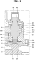
- FIG. 8 is a cross-sectional view showing a state in which an output shaft of a gear assembly is assembled to a housing and a flange
- FIG. 9 is a cross-sectional view showing a state in which a clutch shaft, first gear, and second gear of a gear assembly are assembled to a housing.
- FIG. 10 is a cross-sectional view showing a state in which a clutch shaft of a gear assembly is pressed
- FIG. 11 is a cross-sectional view showing a state in which an adhesive is applied to a power line passage hole of a housing.
- the valve actuator of the present disclosure includes a flange 20 screwed to the tap part 14 of the ball valve 10 but coupled to a housing 30 of the valve actuator by a fastening member such as a screw or bolt.
- the flange 20 is provided separately from the ball valve 10 and the housing 30 and coupled to the ball valve 10 and the housing 30 by a separate fastening member or a separate fastening method, it is possible to additionally install the valve actuator to the ball valves 10 of various standards already installed in the field.
- the flange 20 includes a tap part insertion hole 22, and the tap part insertion hole 22 includes a tap part 21 formed on an inner surface of screwed to the tap part 14 of the ball valve.
- a stem insertion hole 23 communicating with the tap part insertion hole 22 and into which the stem 16 of the ball valve 10 is inserted, and a plurality of long holes 24 positioned at a certain distance from the center of the tap part insertion hole 22 and formed long in the circumferential direction are further provided.
- the flange 20 has a chamfer 25 formed on the inner surface of the tap part insertion hole 22.
- a chamfer 15 having a shape corresponding to the chamfer 25 of the flange 20 is formed at the top of the tap part 14 of the ball valve 10.
- the chamfer 25 of the flange 20 is in contact with the chamfer 15 formed at the upper end of the tap part 14 of the ball valve 10.
- a supporting reaction force is formed by the chamfers 15 and 25 in contact with each other in a state where the flange 20 is screwed to the tap part 14 of the ball valve 10.
- the flange 20 further includes a ring insertion groove 26 formed on the upper surface and in which a second seal ring R2 is disposed
- the housing 30 provides a space in which a motor 40 and a gear assembly 100 provided in the valve actuator are installed.
- the housing 30 includes a lower case 31, an upper case 32 coupled to the lower case 31, an middle plate 33 positioned in an inner space formed by the lower case 31 and the upper case 32, and a flange coupling part 34 provided on the lower case 31 and coupled to the flange 20.
- the motor 40 and the gear assembly 100 will be described as an example of being disposed in a space formed by the middle plate 33 and the lower case 31.
- the motor 40 may be disposed in a space formed by the middle plate 33 and the upper case 32, in this case, the arrangement of the plurality of gears provided in the gear assembly 100 may be different from the arrangement structure described in the present embodiment.
- the flange 20 can be coupled to ball valves 10 of different various standards with starting points of threads provided in the tap part.
- the power line passage hole 44 may be formed in the lower case 31 or the upper case 32.
- the clutch shaft 131 and the first gear set 130 constitute a clutch unit in the valve actuator of the present disclosure.
- a coupling part insertion groove 135a into which the coupling part 133a of the first gear 133 is inserted is formed on the upper surface of the second gear 135.
- the coupling part 133a and the coupling part insertion groove 135a may be formed in shapes corresponding to each other.
- a push-up part 131a is formed on the clutch shaft 131 to push the first gear 133 upward in contact with the coupling part 133a of the first gear 133.
- the push-up part 131a of the clutch shaft 131 is inserted into the push-up part insertion groove 133b formed on the lower surface of the coupling part 133a of the first gear 133.
- the height or thickness of the first gear set 130 in the vertical (Y-Y') direction may be reduced.
- the size of the space formed by the middle plate 33 and the lower case 31 can be further reduced, the size of the valve actuator can be further reduced.
- the snap ring 139 is provided on the clutch shaft 131 to allow the clutch shaft 131 to be manually pulled in case the clutch shaft 131 does not return to the original position due to the malfunction of the return spring 137.
- a third seal ring R3 is disposed on the clutch shaft below the second gear 135.
- a guide groove 31a is formed to guide the third seal ring R3 to move in the vertical (Y-Y') direction together with the clutch shaft 131, the guide groove 31a is formed extending to the inner surface of the lower case 31.
- the moving distance of the clutch shaft 131 in the upward direction is set by a distance D3 between the third seal ring R3 and the second gear 135.
- the second gear 135 may be supported by the third seal ring R3 and/or the lower case 31.
- the downward movement of the second gear 135 may be limited by the third sea ring R3 and/or the lower case 31.
- the downward movement of the second gear 135 may be limited by a separate support shaft.
- the upward movement of the second gear 135 may be limited by the motor 40 and the second gear set 140.
- the second gear set 140 is disposed adjacent to the first gear set 130 in the horizontal (X-X') direction.
- the second gear set 140 is coupled to the first gear 133 and includes the third gear 141 in which a part of the second gear 135 is positioned at the lower portion.
- the second gear set 140 is positioned above the third gear 141 and further includes a fourth gear 143 that rotates integrally with the third gear 141 and is coupled to the output gear 120.
- the third gear 141 and the fourth gear 143 constituting the second gear set 140 may be formed as one body, or may be manufactured separately and coupled between gears with a structure similar to that of the first and second gears 133 and 135.
- the power transmission gear is composed of the first gear set 130 and the second gear set 140, the configuration of the gear assembly 100 can be simplified.
- the lower end of the output shaft 121 coupled with the output gear 120 is coupled to the stem 16 of the ball valve 10, and the upper end of the output shaft 121 protrudes out of the upper case 32.
- a fourth seal ring R4 is disposed between the output shaft 121 and the lower case 31 between the lower end of the output shaft 121 and the output gear 120.
- a fifth seal ring R5 is disposed between the output shaft 121 and the upper case between the upper end of the output shaft 121 and the output gear 120.
- a cap R6 covering the upper end of the output shaft 121 protruding out of the upper case 32 is installed.
- cap R6 covers the minute gap between the output shaft 121 and the upper cover 32.
- valve actuator for controlling the ball valve provided in the air conditioning system has been described, but the valve actuator of the present disclosure can be applied to other valves for controlling a flow path of gas or fluid.
Landscapes
- Engineering & Computer Science (AREA)
- General Engineering & Computer Science (AREA)
- Mechanical Engineering (AREA)
- Physics & Mathematics (AREA)
- Thermal Sciences (AREA)
- Electrically Driven Valve-Operating Means (AREA)
- Taps Or Cocks (AREA)
Claims (11)
- Ventilaktuator, der aufweist:ein Gehäuse (30), das eine Außenseite bildet;einen Motor (40), der in einem Innenraum des Gehäuses (30) angeordnet ist; undeine Zahnradbaugruppe (100), die in einem Innenraum des Gehäuses (30) angeordnet und konfiguriert ist, eine Antriebskraft des Motors (40) auf ein Kugelventil (10) zu übertragen;einen Flansch (20), der dazu ausgelegt ist, am Kugelventil (10) angeschraubt zu sein;mehrere Befestigungselemente (50), die den Flansch (20) mit dem Gehäuse (30) kombinieren und Schrauben oder Bolzen aufweisen,wobei das Gehäuse (30) ein unteres Gehäuse (31) und ein oberes Gehäuse (32) aufweist, das mit dem unteren Gehäuse (31) gekoppelt ist, und das untere Gehäuse (31) eine Flanschverbindungskomponente (34) aufweist, mit der der Flansch (20) über die mehreren Befestigungselemente (50) gekoppelt ist,wobei die Zahnradbaugruppe (100) aufweist:ein Eingangszahnrad (110), das mit einer Rotationswelle des Motors (40) gekoppelt ist und zusammen mit der Rotationswelle rotiert;ein Ausgangszahnrad (120), das vom Eingangszahnrad (110) in einer horizontalen Richtung beabstandet angeordnet ist, dazu ausgelegt ist, mit einem Schaft (16) des Kugelventils (10) gekoppelt zu werden, und konfiguriert ist, eine Rotationskraft des Eingangszahnrads (110) auf den Schaft (16) zu übertragen; undein Kraftübertragungszahnrad (130, 140), das die Rotationskraft des Eingangszahnrads (110) auf das Ausgangszahnrad (120) überträgt,dadurch gekennzeichnet, dass eine Auflagekomponente (31a), auf der eine hervorstehende Klaue (33a) einer mittleren Platte (33), die im Innenraum des Gehäuses (30) angeordnet ist, aufgesetzt ist, am oberen Ende des unteren Gehäuses (31) ausgebildet ist, ein erster Dichtungsring (R1) an der Auflagekomponente (31a) angeordnet ist und der erste Dichtungsring (R1) von einem unteren Ende des oberen Gehäuses (32), einer Auflagekomponente (31a) des unteren Gehäuses (31) und einer hervorstehenden Klaue (33a) der mittleren Platte (33) gehalten wird,dass das Kraftübertragungszahnrad (130, 140) aufweist:eine Kopplungswelle (131), bei der beide Enden mit der mittleren Platte (33) und dem unteren Gehäuse (31) gekoppelt sind, um so in der vertikalen Richtung bewegbar zu sein, und ein erster Zahnradsatz (130), der ein erstes Zahnrad (133) und ein zweites Zahnrad (135) hat, die mit der Kopplungswelle (131) gekoppelt sind und konfiguriert sind, durch eine vertikale Bewegung der Kopplungswelle (131) voneinander getrennt oder miteinander gekoppelt zu werden,und dadurch, dass eine Kopplungskomponente (133a) zum Koppeln des ersten Zahnrads (133) mit dem zweiten Zahnrad (135) von einer unteren Fläche des ersten Zahnrads (133) hervorsteht, das mit dem Eingangszahnrad (110) gekoppelt ist, eine Kopplungskomponenten-Einsetznut (135a), in die die Kopplungskomponente (133a) des ersten Zahnrads (133) eingesetzt ist, auf einer oberen Fläche des zweiten Zahnrads (135) ausgebildet ist, eine Komponente zum Hochdrücken (131a) an der Kopplungswelle (131) ausgebildet ist, um das erste Zahnrad (133) nach oben in Kontakt mit der Kopplungskomponente (133a) des ersten Zahnrads (133) zu drücken, und die Komponente zum Hochdrücken (131a) in einer Einsetznut (133b) der Komponente zum Hochdrücken, die an einer unteren Fläche der Kopplungskomponente (133a) des ersten Zahnrads (133) ausgebildet ist, positioniert ist.
- Ventilaktuator nach Anspruch 1, wobei ein zweiter Dichtungsring (R2) zwischen einer oberen Fläche des Flansches (20) und einer unteren Fläche der Flanschkopplungskomponente (34) angeordnet ist.
- Ventilaktuator nach Anspruch 1 oder 2, wobei das erste Zahnrad (133) durch eine Rückstellfeder (137) in Richtung des zweiten Zahnrads (135) gedrückt wird, die zwischen dem ersten Zahnrad (133) und der mittleren Platte (33) angeordnet ist, und
wobei ein Schnappring (139) an der Kopplungswelle (131) zwischen der Rückstellfeder (137) und einer oberen Fläche des ersten Zahnrads (133) eingebaut ist. - Ventilaktuator nach einem der Ansprüche 1 bis 3, wobei ein dritter Dichtungsring (R3) an der Kopplungswelle (131) unter dem zweiten Zahnrad (135) angeordnet ist, und eine Führungsnut (31a) im unteren Gehäuse (31) ausgebildet ist, wo die Kopplungswelle (131) gekoppelt ist, und dem dritten Dichtungselement (R3) ermöglicht, sich zusammen mit der Kopplungswelle (131) in der vertikalen Richtung zu bewegen, wenn sich die Kopplungswelle (131) in der vertikalen Richtung bewegt.
- Ventilaktuator nach Anspruch 4, wobei ein Bewegungsabstand der Kopplungswelle (131) in einer Richtung nach oben durch einen Abstand (D3) zwischen dem dritten Dichtungselement (R3) und dem zweiten Zahnrad (135) festgelegt wird.
- Ventilaktuator nach Anspruch 5, wobei ein unteres Ende einer Ausgangswelle (121), die mit dem Ausgangszahnrad (120) gekoppelt ist, mit dem Schaft (16) des Kugelventils (10) gekoppelt ist, ein oberes Ende der Ausgangswelle (121) aus dem oberen Gehäuse (32) hervorsteht, und ein vierter Dichtungsring (R4) zwischen der Ausgangswelle (121) und dem unteren Gehäuse (31) zwischen dem unteren Ende der Ausgangswelle (121) und dem Ausgangszahnrad (120) angeordnet ist, und
wobei ein fünfter Dichtungsring (R5) zwischen der Ausgangswelle (121) und dem oberen Gehäuse (32) zwischen dem oberen Ende der Ausgangswelle (121) und dem Ausgangszahnrad (20) angeordnet ist. - Ventilaktuator nach einem der Ansprüche 1 bis 6, wobei das Kraftübertragungszahnrad (130, 140) weiterhin einen zweiten Zahnradsatz (140) aufweist, der benachbart zum ersten Zahnradsatz (130) in der horizontalen Richtung angeordnet ist, und
wobei der zweite Zahnradsatz (140) aufweist:ein drittes Zahnrad (141), das mit dem ersten Zahnrad (133) gekoppelt ist; undein viertes Zahnrad (143), das über dem dritten Zahnrad (141) angeordnet ist, integral mit dem dritten Zahnrad (141) rotiert und mit dem Ausgangszahnrad (120) gekoppelt ist. - Ventilaktuator nach Anspruch 7, wobei eine Kappe (R6), die das obere Ende der Ausgangswelle (121) abdeckt, die aus dem oberen Gehäuse (32) heraussteht, im oberen Gehäuse (32) eingebaut ist, und ein Abstand, der zwischen dem oberen Gehäuse (32) und der Ausgangswelle (121) ausgebildet ist, von der Kappe (R6) abgedeckt wird.
- Ventilaktuator nach einem der Ansprüche 1 bis 8, wobei der Flansch (20) eine Verzweigungskomponenten-Einsetzöffnung (22) aufweist, die eine Verzweigungskomponente (21) hat, die an einer Innenfläche der Verzweigungskomponenten-Einsetzöffnung (22) ausgebildet ist, um in eine Verzweigungskomponente (14) des Kugelventils (10) eingeschraubt zu werden;eine Schafteinsetzöffnung (23), die mit der Verzweigungskomponenten-Einsetzöffnung (22) in Austausch steht und in die ein Schaft (16) des Kugelventils (10) eingesetzt ist; undmehrere Langlöcher (24), die an einem konstanten Abstand von einem Mittelpunkt der Verzweigungskomponenten-Einsetzöffnung (22) angeordnet sind und in der Umfangsrichtung lang ausgebildet sind,wobei die Flanschkopplungskomponente (34) mehrere kreisförmige Nuten (34a) aufweist, in denen jeweils mehrere Befestigungselemente (50), die durch die mehreren Langlöcher (24) hindurchgehen, befestigt sind.
- Ventilaktuator nach Anspruch 9, wobei eine Abschrägung (25) an einer Innenfläche der Verzweigungskomponenten-Einsetzöffnung (22) des Flansches (20) ausgebildet ist, und in einem Zustand, in dem der Flansch (20) und das Kugelventil (10) gekoppelt sind, die Abschrägung (25) des Flansches (20) in Kontakt mit einer Abschrägung (15) steht, die an einem oberen Ende der Verzweigungskomponente (14) des Kugelventils (10) ausgebildet ist.
- Ventilaktuator nach einem der Ansprüche 1 bis 10, wobei das Gehäuse (30) eine Stromleitung-Durchgangsöffnung (44) hat, durch die eine externe Stromleitung (42) zum Zuleiten von Strom an den Motor (40) hindurchgeht,in einem Zustand, in dem die externe Stromleitung (42) hindurchgeht, ein Klebemittel (46) auf die Stromleitungs-Durchgangsöffnung (44) aufgetragen wird,wobei eine Innenfläche des Gehäuses (30) um die Stromleitungs-Durchgangsöffnung (44) mit einer Klebeaufnahmenut (48) vorgesehen ist, die größer als die Stromleitungs-Durchgangsöffnung (44) ausgebildet ist und in der ein Abschnitt des Klebemittels (46) angeordnet wird.
Applications Claiming Priority (1)
| Application Number | Priority Date | Filing Date | Title |
|---|---|---|---|
| KR1020220071891A KR102740365B1 (ko) | 2022-06-14 | 2022-06-14 | 밸브 액튜에이터 |
Publications (2)
| Publication Number | Publication Date |
|---|---|
| EP4293258A1 EP4293258A1 (de) | 2023-12-20 |
| EP4293258B1 true EP4293258B1 (de) | 2025-03-12 |
Family
ID=86497503
Family Applications (1)
| Application Number | Title | Priority Date | Filing Date |
|---|---|---|---|
| EP23174711.4A Active EP4293258B1 (de) | 2022-06-14 | 2023-05-23 | Ventilaktuator |
Country Status (4)
| Country | Link |
|---|---|
| US (1) | US12264752B2 (de) |
| EP (1) | EP4293258B1 (de) |
| KR (1) | KR102740365B1 (de) |
| CN (1) | CN117231792A (de) |
Families Citing this family (1)
| Publication number | Priority date | Publication date | Assignee | Title |
|---|---|---|---|---|
| KR102727361B1 (ko) * | 2022-05-26 | 2024-11-08 | 엘지전자 주식회사 | 밸브 액튜에이터 |
Family Cites Families (21)
| Publication number | Priority date | Publication date | Assignee | Title |
|---|---|---|---|---|
| US3248080A (en) * | 1962-04-18 | 1966-04-26 | American Radiator & Standard | Motor-spring operated valve |
| US5564461A (en) | 1995-11-09 | 1996-10-15 | Bray International, Inc. | Assembly for connecting an actuator to a rotary valve |
| JP2000193129A (ja) * | 1998-10-21 | 2000-07-14 | Kitz Corp | アクチュエ―タ付きバルブ |
| CN1147672C (zh) | 2000-04-27 | 2004-04-28 | 吴龙洙 | 电动球形阀 |
| JP2002188692A (ja) * | 2000-12-20 | 2002-07-05 | Yamatake Corp | バルブ用アクチュエータ |
| US6953182B2 (en) * | 2002-09-13 | 2005-10-11 | Fisher Controls International Llc. | Retainer lock nut for fluid pressure control device |
| US20070108402A1 (en) * | 2005-11-14 | 2007-05-17 | Jeremiah Davis | Sealed hub for motor actuated valve |
| US7641172B2 (en) * | 2006-09-29 | 2010-01-05 | Eaton Corporation | Actuator installation bracket, and valve actuator assembly and fluid shutoff system employing the same |
| KR200458179Y1 (ko) * | 2008-09-26 | 2012-01-25 | 주식회사 노비타 | 전동식 볼밸브의 구동장치 |
| JP6014314B2 (ja) * | 2011-08-12 | 2016-10-25 | 株式会社キッツ | アクチュエータ付き回転弁 |
| KR101557911B1 (ko) * | 2014-08-26 | 2015-10-07 | 강미영 | 자동차의 급발진 방지장치 |
| CN204628727U (zh) * | 2015-03-28 | 2015-09-09 | 江苏华凯矿业科技有限公司 | 矿用本质安全型电动球阀 |
| KR101865567B1 (ko) * | 2016-11-03 | 2018-06-08 | 정은섭 | 회전축에 수밀구조를 갖춘 버터플라이 밸브 조립체 |
| KR20200047567A (ko) * | 2017-09-12 | 2020-05-07 | 바르실라 핀랜드 오이 | 기체 연료 공급 시스템 및 밸브 |
| KR102009387B1 (ko) * | 2017-11-16 | 2019-08-09 | (주)지니스 | 모드전환유닛을 구비한 액추에이터 |
| DE102018109792B4 (de) * | 2018-04-24 | 2024-09-05 | Viega Technology Gmbh & Co. Kg | Adapter zum Anschließen eines Antriebsmittels an einen manuell betätigbaren Absperrhahn und System aus einem solchen Adapter und einem manuell betätigbaren Absperrhahn |
| JP6469288B1 (ja) * | 2018-06-25 | 2019-02-13 | 株式会社コンサス | 弁装置 |
| CA3105056A1 (en) * | 2018-06-29 | 2020-01-02 | Michael Reece HICKS | Motorized ball valve with actuator lock |
| KR20210004245A (ko) * | 2019-07-03 | 2021-01-13 | 엘지전자 주식회사 | 압축기 및 그 제조방법 |
| US11473690B2 (en) * | 2019-09-12 | 2022-10-18 | Vasilii Kasatochkin | Electric actuator for controlling ball valve |
| KR20210152902A (ko) * | 2020-06-09 | 2021-12-16 | 주식회사 모아텍 | 액츄에이터 및 이를 포함하는 전자기기 |
-
2022
- 2022-06-14 KR KR1020220071891A patent/KR102740365B1/ko active Active
-
2023
- 2023-05-11 CN CN202310531857.5A patent/CN117231792A/zh active Pending
- 2023-05-23 EP EP23174711.4A patent/EP4293258B1/de active Active
- 2023-06-14 US US18/209,921 patent/US12264752B2/en active Active
Also Published As
| Publication number | Publication date |
|---|---|
| KR102740365B1 (ko) | 2024-12-10 |
| US20230400115A1 (en) | 2023-12-14 |
| EP4293258A1 (de) | 2023-12-20 |
| US12264752B2 (en) | 2025-04-01 |
| KR20230171566A (ko) | 2023-12-21 |
| CN117231792A (zh) | 2023-12-15 |
Similar Documents
| Publication | Publication Date | Title |
|---|---|---|
| EP4283172B1 (de) | Ventilaktuator | |
| US7163192B2 (en) | Actuator for valve | |
| KR102362453B1 (ko) | 유로 전환 밸브 및 그 조립 방법 | |
| JP6574467B2 (ja) | 直動式電動弁及びその実装方法 | |
| EP4293258B1 (de) | Ventilaktuator | |
| EP4160063B1 (de) | Ventilaktuator | |
| EP4145643A1 (de) | Anpassung eines mehrzweckaktuators | |
| US20030178596A1 (en) | Rotary valve | |
| US4584902A (en) | Valve actuators | |
| US11699936B2 (en) | Rotary actuator having board fixing member meshing with case fastening member | |
| CN219082282U (zh) | 一种内传动阀 | |
| EP1267135B1 (de) | Entspannungsventil | |
| EP4112981B1 (de) | Elektrisches ventil | |
| CA2348571C (en) | Rotary valve | |
| CN219485743U (zh) | 机器人关节模组以及机器人 | |
| EP4137728A1 (de) | Ventilaktuator | |
| JP3150885B2 (ja) | 制御弁 | |
| EP4137729A1 (de) | Ventilaktuator | |
| CN219685367U (zh) | 一种螺丝刀机构 | |
| CN223549904U (zh) | 一种具有应急开关功能的电动执行器 | |
| CN214699425U (zh) | 多用途手自一体阀门执行器 | |
| GB2122034A (en) | Valve actuators |
Legal Events
| Date | Code | Title | Description |
|---|---|---|---|
| PUAI | Public reference made under article 153(3) epc to a published international application that has entered the european phase |
Free format text: ORIGINAL CODE: 0009012 |
|
| STAA | Information on the status of an ep patent application or granted ep patent |
Free format text: STATUS: REQUEST FOR EXAMINATION WAS MADE |
|
| 17P | Request for examination filed |
Effective date: 20230623 |
|
| AK | Designated contracting states |
Kind code of ref document: A1 Designated state(s): AL AT BE BG CH CY CZ DE DK EE ES FI FR GB GR HR HU IE IS IT LI LT LU LV MC ME MK MT NL NO PL PT RO RS SE SI SK SM TR |
|
| RBV | Designated contracting states (corrected) |
Designated state(s): AL AT BE BG CH CY CZ DE DK EE ES FI FR GB GR HR HU IE IS IT LI LT LU LV MC ME MK MT NL NO PL PT RO RS SE SI SK SM TR |
|
| GRAP | Despatch of communication of intention to grant a patent |
Free format text: ORIGINAL CODE: EPIDOSNIGR1 |
|
| STAA | Information on the status of an ep patent application or granted ep patent |
Free format text: STATUS: GRANT OF PATENT IS INTENDED |
|
| INTG | Intention to grant announced |
Effective date: 20241209 |
|
| GRAS | Grant fee paid |
Free format text: ORIGINAL CODE: EPIDOSNIGR3 |
|
| GRAA | (expected) grant |
Free format text: ORIGINAL CODE: 0009210 |
|
| STAA | Information on the status of an ep patent application or granted ep patent |
Free format text: STATUS: THE PATENT HAS BEEN GRANTED |
|
| AK | Designated contracting states |
Kind code of ref document: B1 Designated state(s): AL AT BE BG CH CY CZ DE DK EE ES FI FR GB GR HR HU IE IS IT LI LT LU LV MC ME MK MT NL NO PL PT RO RS SE SI SK SM TR |
|
| REG | Reference to a national code |
Ref country code: GB Ref legal event code: FG4D |
|
| REG | Reference to a national code |
Ref country code: CH Ref legal event code: EP |
|
| REG | Reference to a national code |
Ref country code: DE Ref legal event code: R096 Ref document number: 602023002359 Country of ref document: DE |
|
| REG | Reference to a national code |
Ref country code: IE Ref legal event code: FG4D |
|
| PG25 | Lapsed in a contracting state [announced via postgrant information from national office to epo] |
Ref country code: RS Free format text: LAPSE BECAUSE OF FAILURE TO SUBMIT A TRANSLATION OF THE DESCRIPTION OR TO PAY THE FEE WITHIN THE PRESCRIBED TIME-LIMIT Effective date: 20250612 |
|
| PG25 | Lapsed in a contracting state [announced via postgrant information from national office to epo] |
Ref country code: FI Free format text: LAPSE BECAUSE OF FAILURE TO SUBMIT A TRANSLATION OF THE DESCRIPTION OR TO PAY THE FEE WITHIN THE PRESCRIBED TIME-LIMIT Effective date: 20250312 |
|
| PGFP | Annual fee paid to national office [announced via postgrant information from national office to epo] |
Ref country code: DE Payment date: 20250508 Year of fee payment: 3 |
|
| PG25 | Lapsed in a contracting state [announced via postgrant information from national office to epo] |
Ref country code: ES Free format text: LAPSE BECAUSE OF FAILURE TO SUBMIT A TRANSLATION OF THE DESCRIPTION OR TO PAY THE FEE WITHIN THE PRESCRIBED TIME-LIMIT Effective date: 20250312 |
|
| REG | Reference to a national code |
Ref country code: LT Ref legal event code: MG9D |
|
| PG25 | Lapsed in a contracting state [announced via postgrant information from national office to epo] |
Ref country code: NO Free format text: LAPSE BECAUSE OF FAILURE TO SUBMIT A TRANSLATION OF THE DESCRIPTION OR TO PAY THE FEE WITHIN THE PRESCRIBED TIME-LIMIT Effective date: 20250612 |
|
| PGFP | Annual fee paid to national office [announced via postgrant information from national office to epo] |
Ref country code: IT Payment date: 20250531 Year of fee payment: 3 |
|
| PG25 | Lapsed in a contracting state [announced via postgrant information from national office to epo] |
Ref country code: HR Free format text: LAPSE BECAUSE OF FAILURE TO SUBMIT A TRANSLATION OF THE DESCRIPTION OR TO PAY THE FEE WITHIN THE PRESCRIBED TIME-LIMIT Effective date: 20250312 |
|
| REG | Reference to a national code |
Ref country code: NL Ref legal event code: MP Effective date: 20250312 |
|
| PG25 | Lapsed in a contracting state [announced via postgrant information from national office to epo] |
Ref country code: LV Free format text: LAPSE BECAUSE OF FAILURE TO SUBMIT A TRANSLATION OF THE DESCRIPTION OR TO PAY THE FEE WITHIN THE PRESCRIBED TIME-LIMIT Effective date: 20250312 |
|
| PG25 | Lapsed in a contracting state [announced via postgrant information from national office to epo] |
Ref country code: GR Free format text: LAPSE BECAUSE OF FAILURE TO SUBMIT A TRANSLATION OF THE DESCRIPTION OR TO PAY THE FEE WITHIN THE PRESCRIBED TIME-LIMIT Effective date: 20250613 Ref country code: BG Free format text: LAPSE BECAUSE OF FAILURE TO SUBMIT A TRANSLATION OF THE DESCRIPTION OR TO PAY THE FEE WITHIN THE PRESCRIBED TIME-LIMIT Effective date: 20250312 |
|
| REG | Reference to a national code |
Ref country code: AT Ref legal event code: MK05 Ref document number: 1775242 Country of ref document: AT Kind code of ref document: T Effective date: 20250312 |
|
| PG25 | Lapsed in a contracting state [announced via postgrant information from national office to epo] |
Ref country code: NL Free format text: LAPSE BECAUSE OF FAILURE TO SUBMIT A TRANSLATION OF THE DESCRIPTION OR TO PAY THE FEE WITHIN THE PRESCRIBED TIME-LIMIT Effective date: 20250312 |
|
| PG25 | Lapsed in a contracting state [announced via postgrant information from national office to epo] |
Ref country code: SE Free format text: LAPSE BECAUSE OF FAILURE TO SUBMIT A TRANSLATION OF THE DESCRIPTION OR TO PAY THE FEE WITHIN THE PRESCRIBED TIME-LIMIT Effective date: 20250312 |
|
| PG25 | Lapsed in a contracting state [announced via postgrant information from national office to epo] |
Ref country code: SM Free format text: LAPSE BECAUSE OF FAILURE TO SUBMIT A TRANSLATION OF THE DESCRIPTION OR TO PAY THE FEE WITHIN THE PRESCRIBED TIME-LIMIT Effective date: 20250312 |
|
| PG25 | Lapsed in a contracting state [announced via postgrant information from national office to epo] |
Ref country code: PT Free format text: LAPSE BECAUSE OF FAILURE TO SUBMIT A TRANSLATION OF THE DESCRIPTION OR TO PAY THE FEE WITHIN THE PRESCRIBED TIME-LIMIT Effective date: 20250714 |
|
| PG25 | Lapsed in a contracting state [announced via postgrant information from national office to epo] |
Ref country code: PL Free format text: LAPSE BECAUSE OF FAILURE TO SUBMIT A TRANSLATION OF THE DESCRIPTION OR TO PAY THE FEE WITHIN THE PRESCRIBED TIME-LIMIT Effective date: 20250312 |
|
| PG25 | Lapsed in a contracting state [announced via postgrant information from national office to epo] |
Ref country code: AT Free format text: LAPSE BECAUSE OF FAILURE TO SUBMIT A TRANSLATION OF THE DESCRIPTION OR TO PAY THE FEE WITHIN THE PRESCRIBED TIME-LIMIT Effective date: 20250312 |
|
| PG25 | Lapsed in a contracting state [announced via postgrant information from national office to epo] |
Ref country code: EE Free format text: LAPSE BECAUSE OF FAILURE TO SUBMIT A TRANSLATION OF THE DESCRIPTION OR TO PAY THE FEE WITHIN THE PRESCRIBED TIME-LIMIT Effective date: 20250312 Ref country code: CZ Free format text: LAPSE BECAUSE OF FAILURE TO SUBMIT A TRANSLATION OF THE DESCRIPTION OR TO PAY THE FEE WITHIN THE PRESCRIBED TIME-LIMIT Effective date: 20250312 |
|
| PG25 | Lapsed in a contracting state [announced via postgrant information from national office to epo] |
Ref country code: RO Free format text: LAPSE BECAUSE OF FAILURE TO SUBMIT A TRANSLATION OF THE DESCRIPTION OR TO PAY THE FEE WITHIN THE PRESCRIBED TIME-LIMIT Effective date: 20250312 |
|
| PG25 | Lapsed in a contracting state [announced via postgrant information from national office to epo] |
Ref country code: SK Free format text: LAPSE BECAUSE OF FAILURE TO SUBMIT A TRANSLATION OF THE DESCRIPTION OR TO PAY THE FEE WITHIN THE PRESCRIBED TIME-LIMIT Effective date: 20250312 |
|
| PG25 | Lapsed in a contracting state [announced via postgrant information from national office to epo] |
Ref country code: IS Free format text: LAPSE BECAUSE OF FAILURE TO SUBMIT A TRANSLATION OF THE DESCRIPTION OR TO PAY THE FEE WITHIN THE PRESCRIBED TIME-LIMIT Effective date: 20250712 |
|
| REG | Reference to a national code |
Ref country code: DE Ref legal event code: R097 Ref document number: 602023002359 Country of ref document: DE |
|
| PG25 | Lapsed in a contracting state [announced via postgrant information from national office to epo] |
Ref country code: DK Free format text: LAPSE BECAUSE OF FAILURE TO SUBMIT A TRANSLATION OF THE DESCRIPTION OR TO PAY THE FEE WITHIN THE PRESCRIBED TIME-LIMIT Effective date: 20250312 |
|
| PG25 | Lapsed in a contracting state [announced via postgrant information from national office to epo] |
Ref country code: LU Free format text: LAPSE BECAUSE OF NON-PAYMENT OF DUE FEES Effective date: 20250523 |
|
| PLBE | No opposition filed within time limit |
Free format text: ORIGINAL CODE: 0009261 |
|
| STAA | Information on the status of an ep patent application or granted ep patent |
Free format text: STATUS: NO OPPOSITION FILED WITHIN TIME LIMIT |
|
| REG | Reference to a national code |
Ref country code: CH Ref legal event code: L10 Free format text: ST27 STATUS EVENT CODE: U-0-0-L10-L00 (AS PROVIDED BY THE NATIONAL OFFICE) Effective date: 20260121 |
|
| PG25 | Lapsed in a contracting state [announced via postgrant information from national office to epo] |
Ref country code: MC Free format text: LAPSE BECAUSE OF FAILURE TO SUBMIT A TRANSLATION OF THE DESCRIPTION OR TO PAY THE FEE WITHIN THE PRESCRIBED TIME-LIMIT Effective date: 20250312 |