EP4292887A1 - Impact detection system - Google Patents
Impact detection system Download PDFInfo
- Publication number
- EP4292887A1 EP4292887A1 EP23382598.3A EP23382598A EP4292887A1 EP 4292887 A1 EP4292887 A1 EP 4292887A1 EP 23382598 A EP23382598 A EP 23382598A EP 4292887 A1 EP4292887 A1 EP 4292887A1
- Authority
- EP
- European Patent Office
- Prior art keywords
- bumper
- frame
- area
- foam piece
- detection system
- Prior art date
- Legal status (The legal status is an assumption and is not a legal conclusion. Google has not performed a legal analysis and makes no representation as to the accuracy of the status listed.)
- Granted
Links
Images

Classifications
-
- B—PERFORMING OPERATIONS; TRANSPORTING
- B60—VEHICLES IN GENERAL
- B60R—VEHICLES, VEHICLE FITTINGS, OR VEHICLE PARTS, NOT OTHERWISE PROVIDED FOR
- B60R21/00—Arrangements or fittings on vehicles for protecting or preventing injuries to occupants or pedestrians in case of accidents or other traffic risks
- B60R21/01—Electrical circuits for triggering passive safety arrangements, e.g. airbags, safety belt tighteners, in case of vehicle accidents or impending vehicle accidents
- B60R21/013—Electrical circuits for triggering passive safety arrangements, e.g. airbags, safety belt tighteners, in case of vehicle accidents or impending vehicle accidents including means for detecting collisions, impending collisions or roll-over
- B60R21/0136—Electrical circuits for triggering passive safety arrangements, e.g. airbags, safety belt tighteners, in case of vehicle accidents or impending vehicle accidents including means for detecting collisions, impending collisions or roll-over responsive to actual contact with an obstacle, e.g. to vehicle deformation, bumper displacement or bumper velocity relative to the vehicle
-
- B—PERFORMING OPERATIONS; TRANSPORTING
- B60—VEHICLES IN GENERAL
- B60R—VEHICLES, VEHICLE FITTINGS, OR VEHICLE PARTS, NOT OTHERWISE PROVIDED FOR
- B60R19/00—Wheel guards; Radiator guards, e.g. grilles; Obstruction removers; Fittings damping bouncing force in collisions
- B60R19/02—Bumpers, i.e. impact receiving or absorbing members for protecting vehicles or fending off blows from other vehicles or objects
-
- B—PERFORMING OPERATIONS; TRANSPORTING
- B60—VEHICLES IN GENERAL
- B60R—VEHICLES, VEHICLE FITTINGS, OR VEHICLE PARTS, NOT OTHERWISE PROVIDED FOR
- B60R19/00—Wheel guards; Radiator guards, e.g. grilles; Obstruction removers; Fittings damping bouncing force in collisions
- B60R19/02—Bumpers, i.e. impact receiving or absorbing members for protecting vehicles or fending off blows from other vehicles or objects
- B60R19/18—Bumpers, i.e. impact receiving or absorbing members for protecting vehicles or fending off blows from other vehicles or objects characterised by the cross-section; Means within the bumper to absorb impact
-
- B—PERFORMING OPERATIONS; TRANSPORTING
- B60—VEHICLES IN GENERAL
- B60R—VEHICLES, VEHICLE FITTINGS, OR VEHICLE PARTS, NOT OTHERWISE PROVIDED FOR
- B60R19/00—Wheel guards; Radiator guards, e.g. grilles; Obstruction removers; Fittings damping bouncing force in collisions
- B60R19/02—Bumpers, i.e. impact receiving or absorbing members for protecting vehicles or fending off blows from other vehicles or objects
- B60R19/48—Bumpers, i.e. impact receiving or absorbing members for protecting vehicles or fending off blows from other vehicles or objects combined with, or convertible into, other devices or objects, e.g. bumpers combined with road brushes, bumpers convertible into beds
- B60R19/483—Bumpers, i.e. impact receiving or absorbing members for protecting vehicles or fending off blows from other vehicles or objects combined with, or convertible into, other devices or objects, e.g. bumpers combined with road brushes, bumpers convertible into beds with obstacle sensors of electric or electronic type
-
- B—PERFORMING OPERATIONS; TRANSPORTING
- B60—VEHICLES IN GENERAL
- B60R—VEHICLES, VEHICLE FITTINGS, OR VEHICLE PARTS, NOT OTHERWISE PROVIDED FOR
- B60R21/00—Arrangements or fittings on vehicles for protecting or preventing injuries to occupants or pedestrians in case of accidents or other traffic risks
- B60R21/34—Protecting non-occupants of a vehicle, e.g. pedestrians
- B60R21/38—Protecting non-occupants of a vehicle, e.g. pedestrians using means for lifting bonnets
-
- B—PERFORMING OPERATIONS; TRANSPORTING
- B60—VEHICLES IN GENERAL
- B60R—VEHICLES, VEHICLE FITTINGS, OR VEHICLE PARTS, NOT OTHERWISE PROVIDED FOR
- B60R19/00—Wheel guards; Radiator guards, e.g. grilles; Obstruction removers; Fittings damping bouncing force in collisions
- B60R19/02—Bumpers, i.e. impact receiving or absorbing members for protecting vehicles or fending off blows from other vehicles or objects
- B60R19/18—Bumpers, i.e. impact receiving or absorbing members for protecting vehicles or fending off blows from other vehicles or objects characterised by the cross-section; Means within the bumper to absorb impact
- B60R2019/186—Additional energy absorbing means supported on bumber beams, e.g. cellular structures or material
Definitions
- the object of the present invention is an impact detection system configured for the activation of an active hood system or hood raising system in order to protect a pedestrian in a case of impacting against or being run over by a vehicle.
- the impact detection system object of the present invention allows to increase the sensitivity of the active hood activation sensor, thus allowing to improve the ability to discern if there has been an impact with a pedestrian that requires the activation of the hood to cause the raising thereof, or if there has been an impact with a small object (for example, a ball or a small mass) that does not require raising the hood.
- a small object for example, a ball or a small mass
- the impact detection system object of the present invention is particularly applicable in the field of the industry dedicated to the design and manufacture of motor vehicles.
- motor vehicles can incorporate an active hood system or hood raising system, designed to protect a pedestrian in the event that he or she is hit and/or run over by a vehicle, causing an impact between the person and the front of the vehicle.
- hood By raising the hood, the pedestrian is prevented from hitting the hard parts (for example, the vehicle's engine) located under the hood of the vehicle, reducing the negative consequences of being run over.
- vehicles that comprise active hood systems incorporate a sensor located in the front part of the vehicle.
- This sensor generally comprises a tube filled with a liquid and connected to a pressure sensor (e.g., a hydrostatic pressure sensor) inside the tube.
- the tube is generally attached to the metal crosspiece, i.e., the metal component that extends from right to left side in a direction transverse to the direction of travel of the vehicle, said metal crosspiece being located behind the bumper of the vehicle.
- Said tube is usually embedded in a foam element, or "sandwiched" between the foam and the metal crosspiece.
- the shock causes the strain of the bumper with the subsequent compression of the foam and the tube against the metal crosspiece.
- This compression causes the increase in pressure (e.g., hydrostatic pressure) inside the tube, which is detected by the pressure sensor connected to the tube.
- the pressure levels detected by the sensor are processed by a control unit, so that when a pressure signal having certain characteristics is detected, the mechanisms that cause the raising of hood are activated.
- One drawback related to the stress sensors described above is that since they are located in a low area of the front of the vehicle (in correspondence with the metal crosspiece), they usually have low sensitivity and/or a low ability to discriminate between an impact against a person and an impact against another type of object, such as a bird or a ball. This becomes particularly relevant when the geometry of the vehicle's bumper is strongly concave according to a section made in a plane made up of the direction of travel of the vehicle and the vertical direction.
- the present invention relates to an impact detection system.
- the impact detection system object of the present invention comprises a bumper of a vehicle, a foam piece and a sensing tube filled with a fluid and connected to a pressure sensor (e.g., a hydrostatic pressure sensor) inside the sensing tube.
- a pressure sensor e.g., a hydrostatic pressure sensor
- the sensing tube and the foam piece are fixed to a frame of the bumper.
- the sensing tube is embedded in the foam piece or arranged between the foam piece and the frame of the bumper.
- the impact detection system described above it is possible to dispense with fixing the sensing tube to the metal crosspiece at the front of the vehicle, thereby allowing the sensing tube to be positioned in a way that allows to improve sensitivity to impacts of the vehicle with a person and to be arranged closer to an advanced area of the front of the vehicle, such as a high area of the bumper, this being particularly useful in vehicles that have a bumper with a strongly concave geometry, according to a section made in a plane made up of the direction of travel of the vehicle and the vertical direction.
- the frame of the bumper is understood to be the structural part of said bumper, which provides rigidity against strain or other types of mechanical stress. Said frame is normally not seen from the outside of the vehicle, being covered by the outer skin or covering. Thus, the frame of the bumper is an element that offers little impact strength, but a lot of rigidity, tensile strength and hardness.
- the frame of the bumper may be made of a material such as polyamide (PA) or styrene maleic anhydride (SMA).
- the frame of the bumper comprises a first area and a second area, where the rigidity of the first area is greater than the rigidity of the second area.
- the first area can be made of a material different from the material of the second area.
- the first area of the frame preferably comprises a bottom of the frame, where the term bottom refers to an area of the frame located rearward with respect to a direction of travel of the vehicle. This bottom of the frame is substantially perpendicular to the direction of travel of the vehicle.
- the second area (less rigid area) of the frame may comprise at least a first portion with a thickness less than the thickness of the first area (more rigid area), said first portion forming a first type of weakness.
- the second area (less rigid area) of the frame may comprise at least a second portion with material discontinuities (cavities or perforations that break the continuity of the frame in said second portion of the second area), said second portion forming a second type of weakness.
- the frame of the bumper can also comprise angled surfaces open at an obtuse angle with respect to the first area of the frame. These angled surfaces can help to facilitate the strain of the skin of the bumper with respect to the first area of the frame.
- the detection system comprises controlled strain areas generated by means of different embodiments, which may be complementary to each other. Therefore, said variation in rigidity can be achieved either by a change in material and/or a change in material thickness and/or a material discontinuity and/or an angled arrangement.
- said second areas of the frame to be deformed with respect to the first area, so that the foam piece and the sensing tube are capable of being compressed against the first area of the frame of the bumper and avoiding the displacement of the entire frame towards the rear of the vehicle when an impact against the bumper occurs.
- the foam piece is arranged between a skin (or outer surface) of the bumper and the first area (more rigid area) of the frame of the bumper, and where the foam piece is fixed to the first area of the frame of the bumper.
- skin of the bumper is understood to mean that component of the bumper seen from the outside of the vehicle, the purpose of which is to provide the bumper with a good visual appearance.
- the frame of the bumper comprises the aforementioned angled surfaces open at an obtuse angle with respect to the first area of the frame.
- the foam piece extends in the direction of travel of the vehicle beyond the frame of the bumper (towards the skin of the bumper).
- the impact detection system comprises at least one tab (or cover) configured to position and immobilize the foam piece at least in an azimuthal direction of the vehicle. This configuration is particularly indicated for the first embodiment.
- the foam piece may comprise a plurality of projections configured and arranged to be housed in respective holes arranged in the first area and/or in the second area of the frame of the bumper to position the foam piece with respect to the frame.
- the foam piece is arranged between a skin (or outer surface) of the bumper and the first area (more rigid area) of the frame of the bumper, and where the foam piece is fixed to the second area (less rigid area) of the frame of the bumper, there being a hollow space in the direction of travel of the vehicle between the foam piece and the first area of the frame of the bumper.
- the impact detection system may comprise attachment means between the skin of the bumper and the frame of the bumper, said attachment means being distanced from the foam piece to allow a strain of the skin of the bumper with respect to the frame of the bumper, such that during said strain of the skin of the bumper the foam piece is susceptible to being compressed against the frame of the bumper.
- the second area of the bumper can be configured so that, during said strain of the skin of the bumper, the second area of the frame also deforms, allowing the compression of the foam piece against the frame of the bumper.
- the angled surfaces can be configured so that, during said strain of the skin of the bumper, said angled surfaces deform by increasing the obtuse angle with respect to the first area of the frame, allowing the compression of the foam piece against the frame of the bumper.
- the foam piece is mechanically linked to the metal crosspiece of the vehicle
- the foam is mechanically linked to the frame.
- the skin of the bumper and the frame of the bumper are part of the same component, and are fixed or linked to one another by a plurality of attachment means, such as fixing clips. It is necessary to prevent both components from presenting a single and uniform strain.
- the foam would not deform and would not compress against the frame of the bumper, so the pressure variation signals detected by the pressure sensor would not allow the impact against a person to be correctly detected.
- the foam By linking the foam to the frame and including controlled strain areas, the foam is able to compress against said frame, thus allowing the sensor to experience pressure variations existing in the sensing tube.
- the material for skin of the bumper is preferably a material that allows certain flexibility, but at the same time provides high impact strength.
- An example may be a polypropylene (PP) combined with an ethylene propylene diene rubber (EPDM). It may also be a material formed by a combination of PP, EPDM and talc.
- the present invention relates to an impact detection system.
- Figure 1 shows a stress sensor for vehicle bumpers (6), according to the state of the art.
- Figure 1 shows the sensing tube (1) located in correspondence with the metal crosspiece (2) on the front of the vehicle, where the sensing tube (1) is sandwiched between the metal crosspiece (2) and a foam piece (3).
- the foam piece (3) is susceptible to being compressed against the metal crosspiece (2), causing a variation in pressure (e.g., hydrostatic pressure) inside the sensing tube (1).
- the arrangement of the sensing tube (1) in the metal crosspiece (2) of the front of the vehicle means that the sensing tube (1) is far from the advanced area (5) of the front of the vehicle, according to the direction and sense of travel of the vehicle, which is the area that first impacts against a person (4) in the event of running a person over ( Figure 2 very schematically represents the leg of a person (4)).
- the metal crosspiece (2) could be arranged in the lower area or central area of the bumper (6), the strain of the bumper (6) occurring later in this area than in the more advanced area of said bumper (6).
- the bumper (6) would suffer a strain in correspondence with the advanced area (5) of the front of the vehicle, without the sensing tube (1) detecting anything until the strain of the bumper (6) extends to the recessed area in correspondence with the metal crosspiece (2).
- the sensing tube (1) is not fixed to the metal crosspiece (2) of the front of the vehicle, but rather to the frame (8) of the bumper (6). This makes it possible for the sensing tube (1) to be located in correspondence with the advanced area (5) of the front of the vehicle, i.e., the most prominent area or the one that would first impact the legs of a pedestrian who, according to a strongly concave geometry of the bumper (6), occurs in the highest area of said bumper (6).
- the sensing tube (1) is located (internally) behind the skin (9) of the bumper (6), between a foam piece (3) and the frame (8) of the bumper (6).
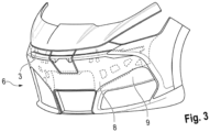
- Figure 3 shows the frame (8) of the bumper (6), by means of a dashed line, being located behind the skin (9) of the bumper (6).
- Figure 4a, Figure 4b and Figure 4c show the way in which the sensing tube (1) is arranged, according to a first embodiment of the impact detection system object of the present invention.
- the sensing tube (1) and the foam piece (3) are arranged between the skin (9) of the bumper (6) of the vehicle, and there may be direct contact or space for air between said skin (9) and the foam piece (3), and a first area (8a) or bottom of the frame (8) of the bumper (6).
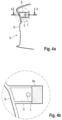
- Figure 4a shows a sectional view of the bumper (6), where the section is taken according to a plane made up of the direction of travel of the vehicle and the vertical direction, at an intermediate coordinate Y0 (according to a Y coordinate axis in the direction transverse to the direction of travel of the vehicle).
- Figure 4b shows a detail of the anchoring or fixing of the sensing tube (1) and of the foam piece (3) to the first area (8a) or bottom of the frame (8) of the bumper (6). It is observed that there is direct contact between the foam piece (3) and the frame (8) of the bumper (6).
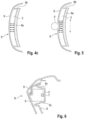
- Figure 4c shows a top section view, according to the section plane AA indicated in Figure 4a .
- the frame (8) of the bumper (6) is a piece of plastic that gives rigidity and consistency to the bumper (6) (it is like the internal skeleton of the bumper (6)), arranged behind the skin (9) of the bumper (6), allowing the bumper (6) to only deform in the event of strong impacts and not deform in the event of small stresses or support on same.
- the skin (9) of the bumper (6) is deformed by pressing the foam piece (3) and the sensing tube (1) against the frame (8), without the first area (8a) or bottom of the frame (8) or the part of the frame (8) to which the sensing tube (1) is fixed being displaced, at least during the start of the impact, integrally with the strain or displacement of said skin (9) of the bumper (6). In this way it is guaranteed that the foam piece (3) and, therefore, the sensing tube (1) will experience strain during the impact.
- the frame (8) is designed so that some parts of the frame (8) present more rigidity and/or robustness than other parts of the frame (8).
- the first area (8a) or bottom of the frame (8) and/or the part or parts of the frame (8) configured for fixing the sensing tube (1) is/are designed with greater rigidity than a second area (8b) of the frame (8) of the bumper (6), thus facilitating that in the event of a frontal impact of an object or a person (4) against the bumper (6) of the vehicle, the skin (9) of the bumper is initially deformed together with the less rigid parts of the frame (8) (the second area (8b) of the frame (8)), with the geometry of the more rigid parts of the frame (8) (the first area (8a) of the frame (8)), specifically the bottom and/or the part of the frame (8) configured for fixing the sensing tube (1), remaining unchanged.
- the different rigidity of the parts of the frame (8) can be achieved by means of different thicknesses in different parts of the frame and/or by means of material discontinuities in different parts of the frame (8), thus generating areas of weakness in the frame (8) that facilitate their strain in said areas of weakness.
- controlled strain points are achieved that allow, particularly those parts of the frame (8) that extend towards the skin (9) of the bumper (6), to deform and allow the compression of the foam piece (3), while the most rigid parts of the frame (8) (the first area (8a) of the frame (8)), specifically the bottom and/or the part of the frame (8) configured for fixing the sensing tube (1), present a relative displacement with respect to said skin (9) of the bumper (6), said relative displacement being an displacement of approximation between both.
- Figure 5 shows an example of the desired situation, wherein after an impact of a person (4) against the bumper (6) of a vehicle, a strain of the skin (9) and the less rigid second area (8b) of the frame (8) occurs, the foam piece (3) thus being deformed against the more rigid first area (8a) of the frame (8), the sensing tube (1) thus pressing against the first area (8a) of the frame (8).
- Figure 4c shows a set of arrows in the X direction (direction of travel/reverse movement of the vehicle). These arrows represent precisely the situation to be avoided, that is, in the event of a frontal impact against the bumper (6) of the vehicle, the skin (9) and frame (8) of the bumper (6) are displaced backwards (in the direction opposite to the direction of travel of the vehicle) as a monolithic assembly, since this would prevent the foam piece (3) and the sensing tube (1) from experiencing strain.
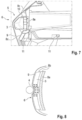
- Figure 6 shows a variant of the first embodiment of the impact detection system.
- the foam piece (3) is fixed to the first area (8a) or bottom of the frame (8) of the bumper (6), and the frame (8) of the bumper has angled surfaces (8c) open at an obtuse angle with respect to the first area (8a) or bottom of the frame (8).
- the foam piece (3) extends beyond the frame (8) in an X direction (direction of travel of the vehicle).
- the foam piece (3) is trapped or enclosed between the skin (9) of the bumper (6) and the frame (8) of the bumper (6), the geometry of the frame with its angled surfaces (8c) in an obtuse angle with respect to the first area (8a) or bottom allow the skin (9) to deform in the event of an impact by a person (4) or heavy object against the advanced area (5) of the front of the vehicle, also allowing the strain of the foam piece (3) without the need for the entire frame (8) to deform and absorb energy during the start of the impact.
- the angled surfaces (8c) may comprise a thickness less than the thickness of the first area (8a) or bottom of the frame (8).
- the first area (8a) or bottom of the frame has a rigidity greater than the rigidity of the angled surfaces (8c).
- the angled surfaces (8c) may comprise specific areas or sections wherein the material thickness is abruptly reduced (as can be seen in the angled surface (8c) located below the foam piece (3) in Figure 6 . This abrupt reduction in material thickness creates an area of weakness in the angled surface(s) (8c).
- the system may comprise tabs (10) or covers, configured to correctly position and immobilize the foam piece (3) in one direction (preferably, at least in an azimuthal direction) or two directions (preferably two mutually perpendicular directions) transverse to the direction of travel of the vehicle.
- the foam piece (3) may comprise a plurality of projections (11) configured to be housed in respective holes in the frame (8) of the bumper (6) to fix the foam piece (3) to the frame (8).
- Figure 8 schematically shows a second embodiment of the impact detection system.
- the first area (8a) or bottom of the frame (8) is far from the skin (9) of the bumper (6), and the foam piece (3) (and optionally also the sensing tube (1)) is fixed to the second area (8b) of the frame (8) (i.e., to a part or parts that are less rigid than the bottom or first area (8a) of the frame (8)), there being a hollow space in the direction of travel of the vehicle between the foam piece (3) and the first area (8a) of the frame (8) of the bumper (6).
Landscapes
- Engineering & Computer Science (AREA)
- Mechanical Engineering (AREA)
- Force Measurement Appropriate To Specific Purposes (AREA)
- Measuring Fluid Pressure (AREA)
Abstract
Description
- The object of the present invention is an impact detection system configured for the activation of an active hood system or hood raising system in order to protect a pedestrian in a case of impacting against or being run over by a vehicle.
- The impact detection system object of the present invention allows to increase the sensitivity of the active hood activation sensor, thus allowing to improve the ability to discern if there has been an impact with a pedestrian that requires the activation of the hood to cause the raising thereof, or if there has been an impact with a small object (for example, a ball or a small mass) that does not require raising the hood.
- The impact detection system object of the present invention is particularly applicable in the field of the industry dedicated to the design and manufacture of motor vehicles.
- Currently, motor vehicles can incorporate an active hood system or hood raising system, designed to protect a pedestrian in the event that he or she is hit and/or run over by a vehicle, causing an impact between the person and the front of the vehicle. By raising the hood, the pedestrian is prevented from hitting the hard parts (for example, the vehicle's engine) located under the hood of the vehicle, reducing the negative consequences of being run over.
- For the activation of the springs or pyrotechnic elements that initiate the raising of the hood, vehicles that comprise active hood systems incorporate a sensor located in the front part of the vehicle. This sensor generally comprises a tube filled with a liquid and connected to a pressure sensor (e.g., a hydrostatic pressure sensor) inside the tube. The tube is generally attached to the metal crosspiece, i.e., the metal component that extends from right to left side in a direction transverse to the direction of travel of the vehicle, said metal crosspiece being located behind the bumper of the vehicle. Said tube is usually embedded in a foam element, or "sandwiched" between the foam and the metal crosspiece. When there is an impact with a heavy object, the shock causes the strain of the bumper with the subsequent compression of the foam and the tube against the metal crosspiece. This compression causes the increase in pressure (e.g., hydrostatic pressure) inside the tube, which is detected by the pressure sensor connected to the tube. The pressure levels detected by the sensor are processed by a control unit, so that when a pressure signal having certain characteristics is detected, the mechanisms that cause the raising of hood are activated.
- Document
WO 2005115803 A1 describes a stress sensor located behind the bumper of a vehicle and linked to the metal crosspiece, as described in the preceding paragraph. - One drawback related to the stress sensors described above is that since they are located in a low area of the front of the vehicle (in correspondence with the metal crosspiece), they usually have low sensitivity and/or a low ability to discriminate between an impact against a person and an impact against another type of object, such as a bird or a ball. This becomes particularly relevant when the geometry of the vehicle's bumper is strongly concave according to a section made in a plane made up of the direction of travel of the vehicle and the vertical direction. In this situation, since the vehicle sensor is located in correspondence with the metal crosspiece (low and recessed area), is far from the most prominent or forward area of the bumper in the direction of travel of the vehicle (high area or "nose" of the bumper) and, therefore, away from the area of impact with a pedestrian in circumstances of being run over.
- In order to solve the aforementioned drawbacks, the present invention relates to an impact detection system.
- The impact detection system object of the present invention comprises a bumper of a vehicle, a foam piece and a sensing tube filled with a fluid and connected to a pressure sensor (e.g., a hydrostatic pressure sensor) inside the sensing tube.
- In a novel manner, in the impact detection system object of the present invention, the sensing tube and the foam piece are fixed to a frame of the bumper. The sensing tube is embedded in the foam piece or arranged between the foam piece and the frame of the bumper.
- By means of the impact detection system described above, it is possible to dispense with fixing the sensing tube to the metal crosspiece at the front of the vehicle, thereby allowing the sensing tube to be positioned in a way that allows to improve sensitivity to impacts of the vehicle with a person and to be arranged closer to an advanced area of the front of the vehicle, such as a high area of the bumper, this being particularly useful in vehicles that have a bumper with a strongly concave geometry, according to a section made in a plane made up of the direction of travel of the vehicle and the vertical direction.
- The frame of the bumper is understood to be the structural part of said bumper, which provides rigidity against strain or other types of mechanical stress. Said frame is normally not seen from the outside of the vehicle, being covered by the outer skin or covering. Thus, the frame of the bumper is an element that offers little impact strength, but a lot of rigidity, tensile strength and hardness. The frame of the bumper may be made of a material such as polyamide (PA) or styrene maleic anhydride (SMA).
- Preferably, the frame of the bumper comprises a first area and a second area, where the rigidity of the first area is greater than the rigidity of the second area. In this way, it is possible to better control which areas of the bumper (and frame of the bumper) will deform first in the event of an impact with a person and to control how the bumper will deform. The first area can be made of a material different from the material of the second area.
- The first area of the frame preferably comprises a bottom of the frame, where the term bottom refers to an area of the frame located rearward with respect to a direction of travel of the vehicle. This bottom of the frame is substantially perpendicular to the direction of travel of the vehicle.
- The second area (less rigid area) of the frame may comprise at least a first portion with a thickness less than the thickness of the first area (more rigid area), said first portion forming a first type of weakness.
- The second area (less rigid area) of the frame may comprise at least a second portion with material discontinuities (cavities or perforations that break the continuity of the frame in said second portion of the second area), said second portion forming a second type of weakness.
- The frame of the bumper can also comprise angled surfaces open at an obtuse angle with respect to the first area of the frame. These angled surfaces can help to facilitate the strain of the skin of the bumper with respect to the first area of the frame.
- In this way, the detection system comprises controlled strain areas generated by means of different embodiments, which may be complementary to each other. Therefore, said variation in rigidity can be achieved either by a change in material and/or a change in material thickness and/or a material discontinuity and/or an angled arrangement. In this way, the intention is for said second areas of the frame to be deformed with respect to the first area, so that the foam piece and the sensing tube are capable of being compressed against the first area of the frame of the bumper and avoiding the displacement of the entire frame towards the rear of the vehicle when an impact against the bumper occurs.
- According to a first embodiment of the impact detection system, the foam piece is arranged between a skin (or outer surface) of the bumper and the first area (more rigid area) of the frame of the bumper, and where the foam piece is fixed to the first area of the frame of the bumper. In the present invention, skin of the bumper is understood to mean that component of the bumper seen from the outside of the vehicle, the purpose of which is to provide the bumper with a good visual appearance.
- Preferably, according to this first embodiment, the frame of the bumper comprises the aforementioned angled surfaces open at an obtuse angle with respect to the first area of the frame.
- Preferably, the foam piece extends in the direction of travel of the vehicle beyond the frame of the bumper (towards the skin of the bumper).
- Also preferably, the impact detection system comprises at least one tab (or cover) configured to position and immobilize the foam piece at least in an azimuthal direction of the vehicle. This configuration is particularly indicated for the first embodiment.
- The foam piece may comprise a plurality of projections configured and arranged to be housed in respective holes arranged in the first area and/or in the second area of the frame of the bumper to position the foam piece with respect to the frame.
- According to a second embodiment of the impact detection system, the foam piece is arranged between a skin (or outer surface) of the bumper and the first area (more rigid area) of the frame of the bumper, and where the foam piece is fixed to the second area (less rigid area) of the frame of the bumper, there being a hollow space in the direction of travel of the vehicle between the foam piece and the first area of the frame of the bumper.
- The impact detection system may comprise attachment means between the skin of the bumper and the frame of the bumper, said attachment means being distanced from the foam piece to allow a strain of the skin of the bumper with respect to the frame of the bumper, such that during said strain of the skin of the bumper the foam piece is susceptible to being compressed against the frame of the bumper.
- Thus, the second area of the bumper can be configured so that, during said strain of the skin of the bumper, the second area of the frame also deforms, allowing the compression of the foam piece against the frame of the bumper.
- Likewise, the angled surfaces can be configured so that, during said strain of the skin of the bumper, said angled surfaces deform by increasing the obtuse angle with respect to the first area of the frame, allowing the compression of the foam piece against the frame of the bumper.
- Unlike the known state of the art, where the foam piece is mechanically linked to the metal crosspiece of the vehicle, according to the present invention, the foam is mechanically linked to the frame. In this embodiment, it is important to ensure that there is a relative strain or displacement between the skin of the bumper (the first element that comes into contact with the impactor or element that strikes the bumper) and the frame (element that provides structural rigidity to the bumper and secures the foam). It is important to note that the skin of the bumper and the frame of the bumper are part of the same component, and are fixed or linked to one another by a plurality of attachment means, such as fixing clips. It is necessary to prevent both components from presenting a single and uniform strain. If this were the case, the foam would not deform and would not compress against the frame of the bumper, so the pressure variation signals detected by the pressure sensor would not allow the impact against a person to be correctly detected. By linking the foam to the frame and including controlled strain areas, the foam is able to compress against said frame, thus allowing the sensor to experience pressure variations existing in the sensing tube.
- The material for skin of the bumper is preferably a material that allows certain flexibility, but at the same time provides high impact strength. An example may be a polypropylene (PP) combined with an ethylene propylene diene rubber (EPDM). It may also be a material formed by a combination of PP, EPDM and talc.
- The following figures have been included as part of the explanation of at least one embodiment of the invention.
-
Figure 1 shows a schematic perspective view of the conventional arrangement of a stress sensing tube between the metal crosspiece and a foam piece. -
Figure 2 shows a schematic side view of a front end of a vehicle in which the bumper has a strongly concave geometry and where the advanced upper end in the direction of travel of the vehicle that first impacts a person's leg in the event of a running over that person has been marked. -
Figure 3 shows a schematic perspective view of the position, with respect to the front end of a vehicle, of the impact detection system according to the present invention. -
Figure 4a shows a schematic side section view of the position, with respect to the front end of a vehicle, of a first embodiment of the impact detection system according to the present invention. -
Figure 4b shows a detail view of the impact detection system ofFigure 4a . -
Figure 4c shows a top schematic view of the impact detection system, according to section AA ofFigure 4a . -
Figure 5 shows a schematic view of the compression of the foam against the frame of the bumper, in the impact detection system ofFigure 4a . -
Figure 6 shows a schematic side section view of a variant of the first embodiment of the impact detection system according to the present invention. -
Figure 7 shows a schematic side section view of a variant of the first embodiment of the impact detection system according to the present invention, wherein the tabs or covers of the frame to immobilize the foam piece are observed. -
Figure 8 shows a schematic upper section view of a second embodiment of the impact detection system according to the present invention. - As mentioned above, the present invention relates to an impact detection system.
-
Figure 1 shows a stress sensor for vehicle bumpers (6), according to the state of the art.Figure 1 shows the sensing tube (1) located in correspondence with the metal crosspiece (2) on the front of the vehicle, where the sensing tube (1) is sandwiched between the metal crosspiece (2) and a foam piece (3). Thus, the foam piece (3) is susceptible to being compressed against the metal crosspiece (2), causing a variation in pressure (e.g., hydrostatic pressure) inside the sensing tube (1). - In the case of vehicles with a front or bumper (6) that has a strongly concave geometry, as shown schematically in
Figure 2 , the arrangement of the sensing tube (1) in the metal crosspiece (2) of the front of the vehicle means that the sensing tube (1) is far from the advanced area (5) of the front of the vehicle, according to the direction and sense of travel of the vehicle, which is the area that first impacts against a person (4) in the event of running a person over (Figure 2 very schematically represents the leg of a person (4)). Thus, depending on the constructive features of the vehicle, the metal crosspiece (2) could be arranged in the lower area or central area of the bumper (6), the strain of the bumper (6) occurring later in this area than in the more advanced area of said bumper (6). - Thus, in the situation described in the previous paragraph, in the event of a person (4) being run over, the bumper (6) would suffer a strain in correspondence with the advanced area (5) of the front of the vehicle, without the sensing tube (1) detecting anything until the strain of the bumper (6) extends to the recessed area in correspondence with the metal crosspiece (2).
- In these circumstances, there is even the possibility that, due to the energy absorbed in the strain of the advanced area (5) of the front of the vehicle, the remaining energy is not enough to deform the recessed area located in correspondence with the metal crosspiece (2) and, therefore, the sensing tube (1) fails to detect the impact, thus failing to activate the hood raising system. In other circumstances, the remaining energy could deform the recessed area located in correspondence with the metal crosspiece (2) but with a value lower than predetermined values, so that an impact pertaining to an object other than an impact of a person could be determined.
- Alternatively or in addition to the above, there is the possibility that the collision of the vehicle with a mass (7) of a smaller size (for example, a ball or a bird) will reach the recessed area of the bumper (6) of the vehicle, in correspondence with the metal crosspiece (2), causing the strain of the bumper (6) in that recessed area, being detected by the sensing tube (1) and activating the raising of the hood. This would lead to the contradiction that the hood raising system would not work (it would not raise the hood) in the event of a person (4) being run over, but it would work in the event of a collision with a mass (7) that should not give rise to the raising of the hood.
- For this reason, as shown in
Figure 3 , in the impact detection system object of the present invention, the sensing tube (1) is not fixed to the metal crosspiece (2) of the front of the vehicle, but rather to the frame (8) of the bumper (6). This makes it possible for the sensing tube (1) to be located in correspondence with the advanced area (5) of the front of the vehicle, i.e., the most prominent area or the one that would first impact the legs of a pedestrian who, according to a strongly concave geometry of the bumper (6), occurs in the highest area of said bumper (6). - Thus, according to the present invention, the sensing tube (1) is located (internally) behind the skin (9) of the bumper (6), between a foam piece (3) and the frame (8) of the bumper (6).
-
Figure 3 shows the frame (8) of the bumper (6), by means of a dashed line, being located behind the skin (9) of the bumper (6). -
Figure 4a, Figure 4b andFigure 4c show the way in which the sensing tube (1) is arranged, according to a first embodiment of the impact detection system object of the present invention. - According to the first embodiment of the impact detection system, the sensing tube (1) and the foam piece (3) are arranged between the skin (9) of the bumper (6) of the vehicle, and there may be direct contact or space for air between said skin (9) and the foam piece (3), and a first area (8a) or bottom of the frame (8) of the bumper (6).
-
Figure 4a shows a sectional view of the bumper (6), where the section is taken according to a plane made up of the direction of travel of the vehicle and the vertical direction, at an intermediate coordinate Y0 (according to a Y coordinate axis in the direction transverse to the direction of travel of the vehicle). -
Figure 4b shows a detail of the anchoring or fixing of the sensing tube (1) and of the foam piece (3) to the first area (8a) or bottom of the frame (8) of the bumper (6). It is observed that there is direct contact between the foam piece (3) and the frame (8) of the bumper (6). -
Figure 4c shows a top section view, according to the section plane AA indicated inFigure 4a . - The frame (8) of the bumper (6) is a piece of plastic that gives rigidity and consistency to the bumper (6) (it is like the internal skeleton of the bumper (6)), arranged behind the skin (9) of the bumper (6), allowing the bumper (6) to only deform in the event of strong impacts and not deform in the event of small stresses or support on same.
- To ensure proper operation of the impact detection system, it must be ensured that in the event of a frontal impact against the bumper (6) of the vehicle, the skin (9) of the bumper (6) is deformed by pressing the foam piece (3) and the sensing tube (1) against the frame (8), without the first area (8a) or bottom of the frame (8) or the part of the frame (8) to which the sensing tube (1) is fixed being displaced, at least during the start of the impact, integrally with the strain or displacement of said skin (9) of the bumper (6). In this way it is guaranteed that the foam piece (3) and, therefore, the sensing tube (1) will experience strain during the impact.
- In order to ensure that the assembly of the skin (9) of the bumper (6) and the frame (8) of the bumper (6) are not displaced backwards as a monolithic assembly or a single assembly in the event of a frontal impact of an object or a person (4) against the bumper (6) of the vehicle, the frame (8) is designed so that some parts of the frame (8) present more rigidity and/or robustness than other parts of the frame (8). Thus, the first area (8a) or bottom of the frame (8) and/or the part or parts of the frame (8) configured for fixing the sensing tube (1) is/are designed with greater rigidity than a second area (8b) of the frame (8) of the bumper (6), thus facilitating that in the event of a frontal impact of an object or a person (4) against the bumper (6) of the vehicle, the skin (9) of the bumper is initially deformed together with the less rigid parts of the frame (8) (the second area (8b) of the frame (8)), with the geometry of the more rigid parts of the frame (8) (the first area (8a) of the frame (8)), specifically the bottom and/or the part of the frame (8) configured for fixing the sensing tube (1), remaining unchanged.
- The different rigidity of the parts of the frame (8) can be achieved by means of different thicknesses in different parts of the frame and/or by means of material discontinuities in different parts of the frame (8), thus generating areas of weakness in the frame (8) that facilitate their strain in said areas of weakness. In this way, controlled strain points are achieved that allow, particularly those parts of the frame (8) that extend towards the skin (9) of the bumper (6), to deform and allow the compression of the foam piece (3), while the most rigid parts of the frame (8) (the first area (8a) of the frame (8)), specifically the bottom and/or the part of the frame (8) configured for fixing the sensing tube (1), present a relative displacement with respect to said skin (9) of the bumper (6), said relative displacement being an displacement of approximation between both.
-
Figure 5 shows an example of the desired situation, wherein after an impact of a person (4) against the bumper (6) of a vehicle, a strain of the skin (9) and the less rigid second area (8b) of the frame (8) occurs, the foam piece (3) thus being deformed against the more rigid first area (8a) of the frame (8), the sensing tube (1) thus pressing against the first area (8a) of the frame (8). -
Figure 4c shows a set of arrows in the X direction (direction of travel/reverse movement of the vehicle). These arrows represent precisely the situation to be avoided, that is, in the event of a frontal impact against the bumper (6) of the vehicle, the skin (9) and frame (8) of the bumper (6) are displaced backwards (in the direction opposite to the direction of travel of the vehicle) as a monolithic assembly, since this would prevent the foam piece (3) and the sensing tube (1) from experiencing strain. -
Figure 6 shows a variant of the first embodiment of the impact detection system. According to this variant, the foam piece (3) is fixed to the first area (8a) or bottom of the frame (8) of the bumper (6), and the frame (8) of the bumper has angled surfaces (8c) open at an obtuse angle with respect to the first area (8a) or bottom of the frame (8). Likewise, the foam piece (3) extends beyond the frame (8) in an X direction (direction of travel of the vehicle). In this way, although the foam piece (3) is trapped or enclosed between the skin (9) of the bumper (6) and the frame (8) of the bumper (6), the geometry of the frame with its angled surfaces (8c) in an obtuse angle with respect to the first area (8a) or bottom allow the skin (9) to deform in the event of an impact by a person (4) or heavy object against the advanced area (5) of the front of the vehicle, also allowing the strain of the foam piece (3) without the need for the entire frame (8) to deform and absorb energy during the start of the impact. - As can be seen in
Figure 6 , the angled surfaces (8c) may comprise a thickness less than the thickness of the first area (8a) or bottom of the frame (8). In any case, the first area (8a) or bottom of the frame has a rigidity greater than the rigidity of the angled surfaces (8c). Likewise, the angled surfaces (8c) may comprise specific areas or sections wherein the material thickness is abruptly reduced (as can be seen in the angled surface (8c) located below the foam piece (3) inFigure 6 . This abrupt reduction in material thickness creates an area of weakness in the angled surface(s) (8c). - As can be seen in
Figure 7 , the system may comprise tabs (10) or covers, configured to correctly position and immobilize the foam piece (3) in one direction (preferably, at least in an azimuthal direction) or two directions (preferably two mutually perpendicular directions) transverse to the direction of travel of the vehicle. - Likewise, as shown in
Figure 7 , the foam piece (3) may comprise a plurality of projections (11) configured to be housed in respective holes in the frame (8) of the bumper (6) to fix the foam piece (3) to the frame (8). -
Figure 8 schematically shows a second embodiment of the impact detection system. In this second embodiment, the first area (8a) or bottom of the frame (8) is far from the skin (9) of the bumper (6), and the foam piece (3) (and optionally also the sensing tube (1)) is fixed to the second area (8b) of the frame (8) (i.e., to a part or parts that are less rigid than the bottom or first area (8a) of the frame (8)), there being a hollow space in the direction of travel of the vehicle between the foam piece (3) and the first area (8a) of the frame (8) of the bumper (6). - In this second embodiment, when an object or person (4) impacts against the bumper (6) of the vehicle, the skin (9) is initially deformed together with the second area (8b) of the frame (8), causing a strain of the foam piece (3) against the first area (8a) or more rigid bottom of the frame (8).
Claims (13)
- An impact detection system comprising a bumper (6) of a vehicle, a foam piece (3) and a sensing tube (1) filled with a fluid and connected to a pressure sensor inside the sensing tube (1), characterized in that the sensing tube (1) and the foam piece (3) are fixed to a frame (8) of the bumper (6) and where the sensing tube (1) is embedded in the foam piece (3) or arranged between the foam piece (3) and the frame (8) of the bumper (6).
- The impact detection system according to claim 1, characterized in that the frame (8) of the bumper (6) comprises a first area (8a) and a second area (8b), where the rigidity of the first area (8a) is greater than the rigidity of the second area (8b).
- The impact detection system according to claim 2, characterized in that the second area (8b) of the frame (8) comprises at least a first portion with a thickness less than the thickness of the first area (8a), said first portion forming a first type of weakness.
- The impact detection system according to claim 2 or 3, characterized in that the second area (8b) of the frame (8) comprises at least a second portion with material discontinuities, said second portion forming a second type of weakness.
- The impact detection system according to any of claims 2 to 4, characterized in that the frame (8) of the bumper (6) comprises angled surfaces (8c) open at an obtuse angle with respect to the first area (8a) of the frame (8).
- The impact detection system according to any of claims 2 to 5, characterized in that the foam piece (3) is arranged between a skin (9) of the bumper (6) and the first area (8a) of the frame (8) of the bumper (6), and where the foam piece (3) is fixed to the first area (8a) of the frame (8) of the bumper (6).
- The impact detection system according to any of the preceding claims, characterized in that the foam piece (3) extends in the direction of travel of the vehicle beyond the frame (8) of the bumper (6).
- The impact detection system according to any of the previous claims, characterized in that the frame (8) comprises at least one tab (10) configured to position and immobilize the foam piece (3) at least in an azimuthal direction of the vehicle.
- The impact detection device according to any one of claims 2 to 8, characterized in that the foam piece (3) comprises a plurality of projections (11) configured and arranged to be housed in respective holes arranged in the first area (8a) and/or in the second area (8b) of the frame (8) of the bumper (6) to position said foam piece (3) with respect to said frame (8).
- The impact detection system according to any of claims 2 to 5, characterized in that the foam piece (3) is arranged between a skin (9) of the bumper (6) and the first area (8a) of the frame (8) of the bumper (6), and where the foam piece (3) is fixed to the second area (8b) of the frame (8) of the bumper (6), there being a hollow space in the direction of travel of the vehicle between the foam piece (3) and the first area (8a) of the frame (8) of the bumper (6).
- The impact detection system according to any one of claims 6 to 10, characterized in that it comprises attachment means between the skin (9) of the bumper (6) and the frame (8) of the bumper (6), said attachment means being distanced from the foam piece (3) to allow a strain of the skin (9) of the bumper (6) with respect to the frame (8) of the bumper (6), such that during said strain of the skin (9) of the bumper (6) the foam piece (3) is susceptible to being compressed against the frame (8) of the bumper (6).
- The impact detection system according to claim 11, characterized in that during said strain of the skin (9) of the bumper (6), the second area (8b) of the bumper (6) is configured to deform, allowing the compression of the foam piece (3) against the frame (8) of the bumper (6).
- The impact detection system according to any of claims 11 or 12 when they depend on claim 5, characterized in that during said strain of the skin (9) of the bumper (6), the angled surfaces (8c) are configured to deform by increasing the obtuse angle with respect to the first area (8a) of the frame (8), allowing the compression of the foam piece (3) against the frame (8) of the bumper (6).
Applications Claiming Priority (1)
| Application Number | Priority Date | Filing Date | Title |
|---|---|---|---|
| ES202230534A ES2957706B2 (en) | 2022-06-16 | 2022-06-16 | Impact detection system |
Publications (2)
| Publication Number | Publication Date |
|---|---|
| EP4292887A1 true EP4292887A1 (en) | 2023-12-20 |
| EP4292887B1 EP4292887B1 (en) | 2025-07-30 |
Family
ID=86862045
Family Applications (1)
| Application Number | Title | Priority Date | Filing Date |
|---|---|---|---|
| EP23382598.3A Active EP4292887B1 (en) | 2022-06-16 | 2023-06-15 | Impact detection system |
Country Status (2)
| Country | Link |
|---|---|
| EP (1) | EP4292887B1 (en) |
| ES (1) | ES2957706B2 (en) |
Citations (9)
| Publication number | Priority date | Publication date | Assignee | Title |
|---|---|---|---|---|
| WO2005115803A1 (en) | 2004-05-13 | 2005-12-08 | Compagnie Plastic Omnium | Device for evaluating strain in the bumper of a motor vehicle, using several sensors |
| DE102011011963A1 (en) * | 2011-02-22 | 2012-08-23 | Continental Automotive Gmbh | Crash sensor for motor vehicle, comprises tube with hollow space, which is elastically deformable in event of collision, where pressure sensor is provided for detecting pressure change in hollow space of tube |
| US20140265445A1 (en) * | 2013-03-14 | 2014-09-18 | Autoliv Asp, Inc. | Compressive Sensor Packaging Techniques |
| DE102013016239A1 (en) * | 2013-09-28 | 2015-04-02 | Daimler Ag | vehicle |
| DE102015104267A1 (en) * | 2014-03-31 | 2015-10-01 | Ford Global Technologies, Llc | IMPACT TUBING FOR PEDESTRIAN PROTECTION SENSOR FOR MOTOR VEHICLE |
| EP2982547A1 (en) * | 2014-08-08 | 2016-02-10 | Toyota Jidosha Kabushiki Kaisha | Vehicle bumper structure including a pressure tube-type pedestrian collision detection sensor |
| WO2016083291A1 (en) * | 2014-11-28 | 2016-06-02 | Volkswagen Aktiengesellschaft | Impact damping component arrangement for a motor vehicle |
| US20160209283A1 (en) * | 2013-08-30 | 2016-07-21 | Robert Bosch Gmbh | Method, Device and System for Checking a Device for a Vehicle for Detecting an Impact |
| US20180141515A1 (en) * | 2016-11-21 | 2018-05-24 | Dr. Ing. H.C. F. Porsche Aktiengesellschaft | Vehicle front structure |
Family Cites Families (2)
| Publication number | Priority date | Publication date | Assignee | Title |
|---|---|---|---|---|
| DE102008022632B4 (en) * | 2008-05-08 | 2018-07-26 | Bayerische Motoren Werke Aktiengesellschaft | Sensor device for detecting an impact on a motor vehicle |
| JP6375896B2 (en) * | 2014-11-26 | 2018-08-22 | 株式会社デンソー | Vehicle collision detection device |
-
2022
- 2022-06-16 ES ES202230534A patent/ES2957706B2/en active Active
-
2023
- 2023-06-15 EP EP23382598.3A patent/EP4292887B1/en active Active
Patent Citations (9)
| Publication number | Priority date | Publication date | Assignee | Title |
|---|---|---|---|---|
| WO2005115803A1 (en) | 2004-05-13 | 2005-12-08 | Compagnie Plastic Omnium | Device for evaluating strain in the bumper of a motor vehicle, using several sensors |
| DE102011011963A1 (en) * | 2011-02-22 | 2012-08-23 | Continental Automotive Gmbh | Crash sensor for motor vehicle, comprises tube with hollow space, which is elastically deformable in event of collision, where pressure sensor is provided for detecting pressure change in hollow space of tube |
| US20140265445A1 (en) * | 2013-03-14 | 2014-09-18 | Autoliv Asp, Inc. | Compressive Sensor Packaging Techniques |
| US20160209283A1 (en) * | 2013-08-30 | 2016-07-21 | Robert Bosch Gmbh | Method, Device and System for Checking a Device for a Vehicle for Detecting an Impact |
| DE102013016239A1 (en) * | 2013-09-28 | 2015-04-02 | Daimler Ag | vehicle |
| DE102015104267A1 (en) * | 2014-03-31 | 2015-10-01 | Ford Global Technologies, Llc | IMPACT TUBING FOR PEDESTRIAN PROTECTION SENSOR FOR MOTOR VEHICLE |
| EP2982547A1 (en) * | 2014-08-08 | 2016-02-10 | Toyota Jidosha Kabushiki Kaisha | Vehicle bumper structure including a pressure tube-type pedestrian collision detection sensor |
| WO2016083291A1 (en) * | 2014-11-28 | 2016-06-02 | Volkswagen Aktiengesellschaft | Impact damping component arrangement for a motor vehicle |
| US20180141515A1 (en) * | 2016-11-21 | 2018-05-24 | Dr. Ing. H.C. F. Porsche Aktiengesellschaft | Vehicle front structure |
Also Published As
| Publication number | Publication date |
|---|---|
| EP4292887B1 (en) | 2025-07-30 |
| ES2957706A1 (en) | 2024-01-24 |
| ES2957706B2 (en) | 2025-07-02 |
Similar Documents
| Publication | Publication Date | Title |
|---|---|---|
| CN104943641B (en) | Crash tubes for pedestrian protection sensors in motor vehicles | |
| US7635042B2 (en) | Device for detecting collision with a vehicle | |
| US9919669B2 (en) | Front section for a motor vehicle | |
| JP2009023407A (en) | Collision detection device | |
| US20090027181A1 (en) | Collision detection apparatus and method for same | |
| CN107585120B (en) | Deformable energy absorber structure for a front cowl assembly of a vehicle | |
| JP2008107232A (en) | Collision detection means | |
| EP2727774A1 (en) | A motor vehicle safety arrangement | |
| JP4968514B2 (en) | Collision detection means | |
| JP2017007368A (en) | Bumper structure for vehicles with pedestrian collision detection sensor | |
| EP4292887B1 (en) | Impact detection system | |
| US12325372B2 (en) | Collision detection apparatus | |
| JP6481475B2 (en) | Vehicle collision detection device | |
| JP6376402B2 (en) | Vehicle collision detection device | |
| JP7779772B2 (en) | Collision detection device | |
| JP7431060B2 (en) | Collision detection device | |
| JP5003636B2 (en) | Vehicle collision detection device | |
| US11679822B2 (en) | Spoiler lip for arranging on a front part of a motor vehicle, and motor vehicle | |
| JP4858786B2 (en) | Vehicle collision detection device | |
| JP2010036663A (en) | Device for detecting collision for vehicle | |
| JP7460396B2 (en) | Collision detection device | |
| EP2792554B1 (en) | Bonnet arrangement | |
| JP6212368B2 (en) | Pedestrian collision detection device | |
| JP2007314159A (en) | Vehicle collision detection device | |
| JP7761192B2 (en) | Vehicle structure |
Legal Events
| Date | Code | Title | Description |
|---|---|---|---|
| PUAI | Public reference made under article 153(3) epc to a published international application that has entered the european phase |
Free format text: ORIGINAL CODE: 0009012 |
|
| STAA | Information on the status of an ep patent application or granted ep patent |
Free format text: STATUS: THE APPLICATION HAS BEEN PUBLISHED |
|
| AK | Designated contracting states |
Kind code of ref document: A1 Designated state(s): AL AT BE BG CH CY CZ DE DK EE ES FI FR GB GR HR HU IE IS IT LI LT LU LV MC ME MK MT NL NO PL PT RO RS SE SI SK SM TR |
|
| STAA | Information on the status of an ep patent application or granted ep patent |
Free format text: STATUS: REQUEST FOR EXAMINATION WAS MADE |
|
| 17P | Request for examination filed |
Effective date: 20240424 |
|
| RBV | Designated contracting states (corrected) |
Designated state(s): AL AT BE BG CH CY CZ DE DK EE ES FI FR GB GR HR HU IE IS IT LI LT LU LV MC ME MK MT NL NO PL PT RO RS SE SI SK SM TR |
|
| GRAP | Despatch of communication of intention to grant a patent |
Free format text: ORIGINAL CODE: EPIDOSNIGR1 |
|
| STAA | Information on the status of an ep patent application or granted ep patent |
Free format text: STATUS: GRANT OF PATENT IS INTENDED |
|
| RIC1 | Information provided on ipc code assigned before grant |
Ipc: B60R 21/0136 20060101AFI20250131BHEP |
|
| INTG | Intention to grant announced |
Effective date: 20250212 |
|
| GRAS | Grant fee paid |
Free format text: ORIGINAL CODE: EPIDOSNIGR3 |
|
| GRAA | (expected) grant |
Free format text: ORIGINAL CODE: 0009210 |
|
| STAA | Information on the status of an ep patent application or granted ep patent |
Free format text: STATUS: THE PATENT HAS BEEN GRANTED |
|
| AK | Designated contracting states |
Kind code of ref document: B1 Designated state(s): AL AT BE BG CH CY CZ DE DK EE ES FI FR GB GR HR HU IE IS IT LI LT LU LV MC ME MK MT NL NO PL PT RO RS SE SI SK SM TR |
|
| REG | Reference to a national code |
Ref country code: GB Ref legal event code: FG4D |
|
| REG | Reference to a national code |
Ref country code: CH Ref legal event code: EP |
|
| REG | Reference to a national code |
Ref country code: DE Ref legal event code: R096 Ref document number: 602023005260 Country of ref document: DE |
|
| REG | Reference to a national code |
Ref country code: IE Ref legal event code: FG4D |
|
| REG | Reference to a national code |
Ref country code: NL Ref legal event code: MP Effective date: 20250730 |
|
| REG | Reference to a national code |
Ref country code: AT Ref legal event code: MK05 Ref document number: 1818616 Country of ref document: AT Kind code of ref document: T Effective date: 20250730 |
|
| PG25 | Lapsed in a contracting state [announced via postgrant information from national office to epo] |
Ref country code: PT Free format text: LAPSE BECAUSE OF FAILURE TO SUBMIT A TRANSLATION OF THE DESCRIPTION OR TO PAY THE FEE WITHIN THE PRESCRIBED TIME-LIMIT Effective date: 20251202 |
|
| PG25 | Lapsed in a contracting state [announced via postgrant information from national office to epo] |
Ref country code: IS Free format text: LAPSE BECAUSE OF FAILURE TO SUBMIT A TRANSLATION OF THE DESCRIPTION OR TO PAY THE FEE WITHIN THE PRESCRIBED TIME-LIMIT Effective date: 20251130 |
|
| PG25 | Lapsed in a contracting state [announced via postgrant information from national office to epo] |
Ref country code: NO Free format text: LAPSE BECAUSE OF FAILURE TO SUBMIT A TRANSLATION OF THE DESCRIPTION OR TO PAY THE FEE WITHIN THE PRESCRIBED TIME-LIMIT Effective date: 20251030 |
|
| REG | Reference to a national code |
Ref country code: LT Ref legal event code: MG9D |
|
| PG25 | Lapsed in a contracting state [announced via postgrant information from national office to epo] |
Ref country code: AT Free format text: LAPSE BECAUSE OF FAILURE TO SUBMIT A TRANSLATION OF THE DESCRIPTION OR TO PAY THE FEE WITHIN THE PRESCRIBED TIME-LIMIT Effective date: 20250730 |
|
| PG25 | Lapsed in a contracting state [announced via postgrant information from national office to epo] |
Ref country code: FI Free format text: LAPSE BECAUSE OF FAILURE TO SUBMIT A TRANSLATION OF THE DESCRIPTION OR TO PAY THE FEE WITHIN THE PRESCRIBED TIME-LIMIT Effective date: 20250730 |
|
| PG25 | Lapsed in a contracting state [announced via postgrant information from national office to epo] |
Ref country code: HR Free format text: LAPSE BECAUSE OF FAILURE TO SUBMIT A TRANSLATION OF THE DESCRIPTION OR TO PAY THE FEE WITHIN THE PRESCRIBED TIME-LIMIT Effective date: 20250730 Ref country code: NL Free format text: LAPSE BECAUSE OF FAILURE TO SUBMIT A TRANSLATION OF THE DESCRIPTION OR TO PAY THE FEE WITHIN THE PRESCRIBED TIME-LIMIT Effective date: 20250730 |
|
| PG25 | Lapsed in a contracting state [announced via postgrant information from national office to epo] |
Ref country code: GR Free format text: LAPSE BECAUSE OF FAILURE TO SUBMIT A TRANSLATION OF THE DESCRIPTION OR TO PAY THE FEE WITHIN THE PRESCRIBED TIME-LIMIT Effective date: 20251031 |
|
| PG25 | Lapsed in a contracting state [announced via postgrant information from national office to epo] |
Ref country code: SE Free format text: LAPSE BECAUSE OF FAILURE TO SUBMIT A TRANSLATION OF THE DESCRIPTION OR TO PAY THE FEE WITHIN THE PRESCRIBED TIME-LIMIT Effective date: 20250730 |
|
| PG25 | Lapsed in a contracting state [announced via postgrant information from national office to epo] |
Ref country code: LV Free format text: LAPSE BECAUSE OF FAILURE TO SUBMIT A TRANSLATION OF THE DESCRIPTION OR TO PAY THE FEE WITHIN THE PRESCRIBED TIME-LIMIT Effective date: 20250730 |
|
| PG25 | Lapsed in a contracting state [announced via postgrant information from national office to epo] |
Ref country code: PL Free format text: LAPSE BECAUSE OF FAILURE TO SUBMIT A TRANSLATION OF THE DESCRIPTION OR TO PAY THE FEE WITHIN THE PRESCRIBED TIME-LIMIT Effective date: 20250730 Ref country code: BG Free format text: LAPSE BECAUSE OF FAILURE TO SUBMIT A TRANSLATION OF THE DESCRIPTION OR TO PAY THE FEE WITHIN THE PRESCRIBED TIME-LIMIT Effective date: 20250730 |
|
| PG25 | Lapsed in a contracting state [announced via postgrant information from national office to epo] |
Ref country code: RS Free format text: LAPSE BECAUSE OF FAILURE TO SUBMIT A TRANSLATION OF THE DESCRIPTION OR TO PAY THE FEE WITHIN THE PRESCRIBED TIME-LIMIT Effective date: 20251030 |
|
| PG25 | Lapsed in a contracting state [announced via postgrant information from national office to epo] |
Ref country code: ES Free format text: LAPSE BECAUSE OF FAILURE TO SUBMIT A TRANSLATION OF THE DESCRIPTION OR TO PAY THE FEE WITHIN THE PRESCRIBED TIME-LIMIT Effective date: 20250730 |
|
| PG25 | Lapsed in a contracting state [announced via postgrant information from national office to epo] |
Ref country code: SM Free format text: LAPSE BECAUSE OF FAILURE TO SUBMIT A TRANSLATION OF THE DESCRIPTION OR TO PAY THE FEE WITHIN THE PRESCRIBED TIME-LIMIT Effective date: 20250730 |
|
| PG25 | Lapsed in a contracting state [announced via postgrant information from national office to epo] |
Ref country code: DK Free format text: LAPSE BECAUSE OF FAILURE TO SUBMIT A TRANSLATION OF THE DESCRIPTION OR TO PAY THE FEE WITHIN THE PRESCRIBED TIME-LIMIT Effective date: 20250730 |
|
| PG25 | Lapsed in a contracting state [announced via postgrant information from national office to epo] |
Ref country code: IT Free format text: LAPSE BECAUSE OF FAILURE TO SUBMIT A TRANSLATION OF THE DESCRIPTION OR TO PAY THE FEE WITHIN THE PRESCRIBED TIME-LIMIT Effective date: 20250730 |
|
| PG25 | Lapsed in a contracting state [announced via postgrant information from national office to epo] |
Ref country code: CZ Free format text: LAPSE BECAUSE OF FAILURE TO SUBMIT A TRANSLATION OF THE DESCRIPTION OR TO PAY THE FEE WITHIN THE PRESCRIBED TIME-LIMIT Effective date: 20250730 |
|
| PG25 | Lapsed in a contracting state [announced via postgrant information from national office to epo] |
Ref country code: SK Free format text: LAPSE BECAUSE OF FAILURE TO SUBMIT A TRANSLATION OF THE DESCRIPTION OR TO PAY THE FEE WITHIN THE PRESCRIBED TIME-LIMIT Effective date: 20250730 Ref country code: EE Free format text: LAPSE BECAUSE OF FAILURE TO SUBMIT A TRANSLATION OF THE DESCRIPTION OR TO PAY THE FEE WITHIN THE PRESCRIBED TIME-LIMIT Effective date: 20250730 |