EP4291813B1 - Rohraufhänger - Google Patents
Rohraufhänger Download PDFInfo
- Publication number
- EP4291813B1 EP4291813B1 EP22703409.7A EP22703409A EP4291813B1 EP 4291813 B1 EP4291813 B1 EP 4291813B1 EP 22703409 A EP22703409 A EP 22703409A EP 4291813 B1 EP4291813 B1 EP 4291813B1
- Authority
- EP
- European Patent Office
- Prior art keywords
- pipe
- hanger part
- connecting rod
- hanger
- end portion
- Prior art date
- Legal status (The legal status is an assumption and is not a legal conclusion. Google has not performed a legal analysis and makes no representation as to the accuracy of the status listed.)
- Active
Links
Images


Classifications
-
- F—MECHANICAL ENGINEERING; LIGHTING; HEATING; WEAPONS; BLASTING
- F16—ENGINEERING ELEMENTS AND UNITS; GENERAL MEASURES FOR PRODUCING AND MAINTAINING EFFECTIVE FUNCTIONING OF MACHINES OR INSTALLATIONS; THERMAL INSULATION IN GENERAL
- F16L—PIPES; JOINTS OR FITTINGS FOR PIPES; SUPPORTS FOR PIPES, CABLES OR PROTECTIVE TUBING; MEANS FOR THERMAL INSULATION IN GENERAL
- F16L3/00—Supports for pipes, cables or protective tubing, e.g. hangers, holders, clamps, cleats, clips, brackets
- F16L3/08—Supports for pipes, cables or protective tubing, e.g. hangers, holders, clamps, cleats, clips, brackets substantially surrounding the pipe, cable or protective tubing
- F16L3/10—Supports for pipes, cables or protective tubing, e.g. hangers, holders, clamps, cleats, clips, brackets substantially surrounding the pipe, cable or protective tubing divided, i.e. with two members engaging the pipe, cable or protective tubing
- F16L3/11—Supports for pipes, cables or protective tubing, e.g. hangers, holders, clamps, cleats, clips, brackets substantially surrounding the pipe, cable or protective tubing divided, i.e. with two members engaging the pipe, cable or protective tubing and hanging from a pendant
-
- F—MECHANICAL ENGINEERING; LIGHTING; HEATING; WEAPONS; BLASTING
- F16—ENGINEERING ELEMENTS AND UNITS; GENERAL MEASURES FOR PRODUCING AND MAINTAINING EFFECTIVE FUNCTIONING OF MACHINES OR INSTALLATIONS; THERMAL INSULATION IN GENERAL
- F16L—PIPES; JOINTS OR FITTINGS FOR PIPES; SUPPORTS FOR PIPES, CABLES OR PROTECTIVE TUBING; MEANS FOR THERMAL INSULATION IN GENERAL
- F16L3/00—Supports for pipes, cables or protective tubing, e.g. hangers, holders, clamps, cleats, clips, brackets
- F16L3/08—Supports for pipes, cables or protective tubing, e.g. hangers, holders, clamps, cleats, clips, brackets substantially surrounding the pipe, cable or protective tubing
- F16L3/12—Supports for pipes, cables or protective tubing, e.g. hangers, holders, clamps, cleats, clips, brackets substantially surrounding the pipe, cable or protective tubing comprising a member substantially surrounding the pipe, cable or protective tubing
- F16L3/133—Supports for pipes, cables or protective tubing, e.g. hangers, holders, clamps, cleats, clips, brackets substantially surrounding the pipe, cable or protective tubing comprising a member substantially surrounding the pipe, cable or protective tubing and hanging from a pendant
-
- F—MECHANICAL ENGINEERING; LIGHTING; HEATING; WEAPONS; BLASTING
- F16—ENGINEERING ELEMENTS AND UNITS; GENERAL MEASURES FOR PRODUCING AND MAINTAINING EFFECTIVE FUNCTIONING OF MACHINES OR INSTALLATIONS; THERMAL INSULATION IN GENERAL
- F16L—PIPES; JOINTS OR FITTINGS FOR PIPES; SUPPORTS FOR PIPES, CABLES OR PROTECTIVE TUBING; MEANS FOR THERMAL INSULATION IN GENERAL
- F16L3/00—Supports for pipes, cables or protective tubing, e.g. hangers, holders, clamps, cleats, clips, brackets
- F16L3/14—Hangers in the form of bands or chains
Definitions
- the present invention relates to a pipe hanger for supporting pipes, the pipe hanger comprising an upper hanger part, a lower hanger part and a connecting rod, the upper hanger part being adapted to be mounted to a support member, wherein the upper hanger part has a centre portion and two downwardly extending depending arms at the sides thereof, which upper hanger part includes on each of its depending arms at least one bore, which bores are at least partially aligned,
- Pipe hangers of this type are known in the art as a 'Clevis hangers'. These pipe hangers may be used to support pipes, e g. to suspend them from a structure, e g. a ceiling or other overhead support.
- Clevis hangers comprise an upper hanger part configured to be coupled with the structure and a U-shaped lower hanger part defining a pipe receiving saddle.
- EP 3 405 711 B1 and US 5 848 770 A each show a Clevis hanger having a connecting rod formed as a bolt with a bolt head.
- US 4 019706 A discloses a Clevis hanger with a connecting rod having two bent end portions.
- US 2006/0180713 A1 discloses in Fig. 10 a pipe hanger with an L-shaped connecting rod.
- the connection rod has a protrusion at one end opposite the bent end portion.
- the leg of the lower hanger part has a keyhole shape.
- the rod with protrusion is aligned with the keyhole shape and passed through. When the protrusion has passed the keyhole, the rod is rotated to misalign the protrusion with the keyhole.
- the bent end portion tends to hang down under the influence of gravity and thereby rotates the rod and misaligns the protrusion and the keyhole.
- the invention has for an object to provide a pipe hanger, which allows for easy installation in a wider variety of situations than the known clevis hangers, whilst also constituting a rigid structure when the pipe hanger is installed.
- the bent end portion of the connecting rod is directed upwardly when the upper hanger portion is suspended from an overhead structure. Also during installation of the pipe hanger and installation of a pipe in the pipe hanger the bent end portion of the connecting rod extends upwardly whereby the bent end portion of the connecting rod provides a suspending hook, from which the lower hanger part can be suspended with one leg.
- This allows installation of a pipe in the hanger, wherein the lower hanger part is initially disassembled, or only half assembled with the upper part in an open state suspending from the mentioned one leg. The pipe is then arranged in the lower part of the pipe hanger after which the hanger is closed.
- a third option is foreseen, in which first the upper and lower hanger part are assembled in a closed state by means of the connecting rod. Next, the pipe can slide in its axial direction through the assembled hanger.
- the bent end portion which is received in the recess, which couples a swivelling movement of the lower hanger part around the axis of the connecting rod with a rotational movement of the connecting rod.
- the pipe hanger can absorb a possible thermal expansion of the pipe in the hanger in an axial direction.
- the bent end portion which is received in the recess, is secured in its position and rotation of the connecting rod is coupled to the swivelling movement of the lower hanger part.
- the rotational coupling of the connection rod and the lower hanger part warrants that the connection cannot be released inadvertently while the pipe hanger is in the closed state.
- the connecting rod is made by cutting a threaded rod to length and bending one end portion to form the bent end portion. This allows an easy and cost effective manufacturing of the connecting rod from a length of a standard threaded rod, which is a staple product.
- the end portion of the connecting rod is bent at a substantially right angle with respect to the shank.
- the outwardly projecting flange is bent at a substantially right angle with respect to the leg.
- the bent end portion of the connecting rod is received in the recess of the flange of the leg at a substantially right angle.
- the bores of the legs of the lower hanger part are elongate bores. These elongate bores preferably extend vertically along the respective legs.
- the vertical elongate bore especially gives room to manoeuvre when aligning the bore in the leg with the connecting rod.
- the recess is formed in an edge of the flange, in particular the recess is provided in an outwardly facing edge of the flange.
- the recess may have a substantially semi-cylindrical shape.
- the recess may have a dimension corresponding to about half the diameter of the connecting rod, which warrants the coupling of the connecting rod and the lower hanger part.
- the recess is formed as an elongate hole provided in the flange, said elongate hole having a longitudinal axis extending in the outward direction.
- the other one of the legs has a bent end portion, which is bent outwardly over an angle less than 90° with respect to the leg, preferably an angle in the range 30° - 60°.
- the invention also relates to a method according to any of the claims 13-15.
- Fig. 1 shows a pipe hanger 1 for supporting pipes.
- the pipe hanger 1 is of the type which is often referred to in the art as a 'clevis hanger'.
- the pipe hanger 1 comprises an upper hanger part 2 and a lower hanger part 3.
- the upper hanger part 2 and the lower hanger part 3 are connected by a connecting rod 4.
- the upper hanger part 2 has a mounting hole 22 in a centre portion 21, which is adapted to be mounted to a support member, such as a threaded rod 5 as is shown in Fig. 7 , for example.
- the threaded rod 5 is suspended from an overhead structure, which may be a ceiling or another support structure.
- the upper hanger part 2 has a centre portion 21 and two downwardly extending depending arms 23 at the sides thereof.
- the upper hanger part 2 includes on each of its depending arms 23 at least one bore 24.
- the bores 24 are aligned in the embodiment shown in the figures.
- the bores 24 are in the embodiment shown in the figures provided with a female thread.
- the lower hanger part 3 which shown separately in Fig. 3 , has a saddle portion 31 for supporting a pipe and two upwardly extending legs 32 at the sides thereof.
- the lower hanger part 3 includes on each of the legs at least one aperture 33.
- the apertures 33 are aligned.
- the apertures 33 have an elongate shape or a slotted shape with a longitudinal axis extending in a longitudinal direction of the legs 32.
- the elongate shape of the apertures 33 provides some manoeuvring space for the lower hanger part 3 with respect to the upper hanger part 2 during assembly and installation of a pipe as will become apparent further below.
- the pipe hanger 1 is shown in Fig. 1 in a closed state.
- the depending arms 23 of the upper hanger part 2 and the corresponding legs 32 of the lower hanger part 3 are coupled by the connecting rod 4, which is passed through the aligned bores 24 of the upper hanger part 2 and apertures 33 in the legs 32 of the lower hanger part 3.
- the connecting rod 4 defines a substantially horizontal rotational axis, around which the lower hanger part 3 may swivel with respect to the upper hanger part 2.
- the depending arms 23 of the upper hanger part 2 and the associated legs 32 of the lower hanger part 3 have an overlap, indicated by reference numeral 6, so as to allow for aligning the respective bores 24 and apertures 33 for passing through the connecting rod 4.
- the legs 32 of the lower hanger part 3 are arranged on an outer side of the depending arms 23 of the upper hanger part 2 in the overlap region 6.
- the connecting rod 4 is preferably made of a threaded rod cut to length. It comprises a substantially straight shank 41 and an end portion 42 bent with respect to the shank 41.
- the shank 41 is passed through the bores 24 and apertures 33 of the upper hanger part 2 and the lower hanger part 3.
- the male thread on the shank 41 cooperates with the female thread in the bores 24.
- the legs 32 of the lower hanger part each have an outwardly bent flange.
- One of the legs 32 has an outwardly projecting flange 34, which is bent under a right angle with respect to the leg 32.
- the flange 34 has at an outer edge 35 wherein a recess 36 is formed, see Fig. 3 .
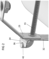
- the recess 36 is open towards the edge 35 of the flange 34 and is adapted to receive the bent end portion 42 of the connecting rod 4 as is shown in more detail in Fig. 2 .
- the end portion 42 that is received in the recess 36 in the flange 34 interlocks the lower hanger part 3 and the connection rod 4 in a rotational direction around the horizontal rotational axis in the closed state of the pipe hanger 1.
- the recess 36 has a depth, which is about half the diameter of the bent end portion 42 of the connecting rod 4, but may also be less deep.
- a recess 136 is provided in the flange 134, which is an aperture having a closed contour.
- the aperture is formed as an elongate hole having a longitudinal axis.
- a nut 5 is screwed on an end 43 of the shank of the connecting rod 4.
- the other leg 32 has a flange 37, which is bent outwards with respect to the leg under an angle less than 90°, preferably an angle in the range 30°- 60°.
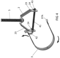
- This flange 37 provides a guiding surface 37A (cf. Fig. 4 ) upon closing of the pipe hanger 1, which guiding surface slides along the lower end of the corresponding depending arm 23 and an end 43 of the shank of the connecting rod 4 that extends through the overlapped arm 23 and leg 32.
- the upper hanger portion 2 is suspended from an overhead support structure by means of a threaded rod 5 as is shown in Fig. 4 .
- the shank 41 of the connecting rod 4 is screwed through the bores 24 in the arms 23 of the upper hanger part 2.
- the connecting rod 4 is rotated in a position such that the bent end portion 42 extends upwardly and provides a hook for suspending the lower hanger part 3 on.
- the friction in the screw connection maintains the connecting rod 4 in this position.
- Fig. 4 is shown how the end of the leg 32, which is provided with the flange 34, is hooked with an elongate aperture 33 on the bent portion 42 of the connecting rod 4. This is in a tilted position of the lower hanger part 3 with respect to the upper hanger part 2, which is allowed by the elongate shape of the aperture 33.
- the hanger 1 is now assembled but in an open position.
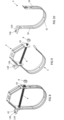
- Fig. 5 a first method to install a pipe in the pipe hanger 1.
- the lower hanger part 3 is suspended from the hook formed by the bent end portion 42 of the connecting rod 4.
- the pipe 7 is moved transversely in the open side of the hanger 1 and placed in the lower hanger part 3.
- the lower hanger part 3 can be swivelled towards the closed position in which the free leg having the guiding flange 37 is hooked over the end 43 of the shank 41 of the connecting rod 4.
- the inclined flange 37 makes sure that the flange and the associated leg 32 is guided outwardly from the corresponding arm 23 of the upper hanger part 2 and is guided outward of the end 43 of the shank 41.
- a nut In the closed state (cf. Fig. 1 ) a nut can be screwed on the end 43 of the shank 41, whereby the closed position of the hanger 1 is secured.
- the flange 34 By swivelling the lower hanger part 3 upward to the closed position, the flange 34 is swivelled and the recess 36 is moved over the bent end portion 42 of the connecting rod, which interlocks the lower hanger part 3 with the connecting rod 4.
- This has the effect that the lower hanger part 3 and the connecting rod 4 can mutually rotate around the rotation axis defined by the shank 41 of the connecting rod 4.
- a swivelling movement of the lower hanger part 3 around the rotational axis also rotates the connecting rod, which thereby moves slightly through the threaded bores 24.
- the connecting rod 4 is however screwed so far through the threaded bores 24 that the connecting rod 4 cannot come loose from the upper hanger part 2. This allows inter alia that the pipe 7 can thermally expand in the longitudinal direction thereby causing a swivelling of the lower hanger part 3 with respect to the upper hanger part 2.
- FIGs 6A and 6B Another method to install a pipe in the pipe hanger 1 is illustrated in Figs 6A and 6B .
- the lower hanger part 3 is not initially suspended from the hook formed by the end portion 42 of the connecting rod 4, but the pipe 7 is arranged in the separate lower hanger part 3.
- the lower hanger part 3 with the pipe 7 in it are moved towards the upper hanger part 2 (cf. Fig. 6A ) and the lower hanger part is hooked over the bent end portion 42 of the connecting rod (cf. Fig. 6B ).
- the pipe hanger 1 can be closed and locked in the same manner as is described in relation with Fig. 5 .
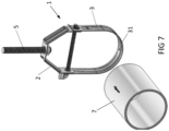
- FIG. 7 Yet another method to install a pipe 7 in the pipe hanger 1 is illustrated in Fig. 7 .
- the pipe hanger 1 is already in the closed state.
- a nut on the end 43 of the shank 41 of the connecting rod 4 this may well be the case to avoid releasing the leg 32 on that side of the hanger 1 from the end 43.
- the pipe 7 is moved in the axial direction into the closed hanger 1. Because the bent end portion 42 of the connecting rod 4 is received in the recess 36, the lower hanger part 3 is allowed to swivel while rotating the connecting rod 4. The slight rotation of the connecting rod 4 however cannot decouple the connecting rod 4 from the arms 23 of the upper hanger part 2.
- the pipe hanger 1 according to the invention is versatile in its use. On site, the user can select the way to install the pipe hanger 1 and to arrange the pipe 7 in the pipe hanger 1 as is best fit for the circumstances on site.
Landscapes
- Engineering & Computer Science (AREA)
- General Engineering & Computer Science (AREA)
- Mechanical Engineering (AREA)
- Holders For Apparel And Elements Relating To Apparel (AREA)
- Supports For Pipes And Cables (AREA)
Claims (15)
- Rohraufhänger (1), umfassend einen oberen Aufhängerteil (2), einen unteren Aufhängerteil (3) und eine Verbindungsstange (4), wobei der obere Aufhängerteil (2) dazu angepasst ist, an einem Trägerelement (5) befestigt zu werden, wobei- der obere Aufhängerteil (2) einen mittigen Abschnitt (21) und zwei sich nach unten erstreckende herabhängende Arme (23) an dessen Seiten aufweist, wobei der obere Aufhängerteil (2) an jedem seiner herabhängenden Arme (23) mindestens eine Bohrung (24) aufweist, wobei die Bohrungen (24) zumindest teilweise fluchten,- der untere Aufhängerteil (3) einen Sattelabschnitt (31) zum Abstützen eines Rohrs und zwei sich nach oben erstreckende Schenkel (32) an dessen Seiten aufweist, wobei der untere Aufhängerteil (3) an jedem der Schenkel (32) mindestens eine Öffnung (33) aufweist, wobei die Öffnungen (33) zumindest teilweise fluchten,wobei in einem geschlossenen Zustand des Rohraufhängers (1) die herabhängenden Arme (23) des oberen Aufhängerteils (2) und die entsprechenden Schenkel (32) des unteren Aufhängerteils (3) durch die Verbindungsstange (4) gekoppelt sind, die durch die Bohrungen (24, 33) sowohl des oberen Aufhängerteils (2) als auch des unteren Aufhängerteils (3) geführt ist, wobei die Verbindungsstange (4) eine im Wesentlichen horizontale Drehachse definiert,wobei in dem geschlossenen Zustand die herabhängenden Arme (23) des oberen Aufhängerteils (2) und die entsprechenden Schenkel (32) des unteren Aufhängerteils (3) einen überlappten Abschnitt (6) aufweisen, um ein Ausrichten der jeweiligen Bohrungen (24, 33) der Arme (23) und der Schenkel (32) zum Durchführen der Verbindungsstange (4) zu ermöglichen,wobei die Verbindungsstange (4) einen im Wesentlichen geraden Schaft (4) und einen in Bezug auf den Schaft (41) abgewinkelten Endabschnitt (42) umfasst, wobei der Schaft (41) durch die Bohrungen (24, 33) sowohl des oberen Aufhängerteils (2) als auch des unteren Aufhängerteils (3) geführt ist,dadurch gekennzeichnet, dass die Schenkel (32) des unteren Aufhängerteils (3) in dem überlappten Abschnitt (6) an einer Außenseite der herabhängenden Arme (23) des oberen Aufhängerteils (2) angeordnet sind,dass zumindest der Schaft (41) der Verbindungsstange (4) zumindest teilweise mit einem Außengewinde versehen ist, wobei mindestens eine der Bohrungen (24) der herabhängenden Arme (23) ein Gewindeloch ist, wobei im geschlossenen Zustand der Schaft (41) der Verbindungsstange (4) durch das mindestens eine Gewindeloch (24) geschraubt ist, unddass mindestens einer der Schenkel (32) des unteren Aufhängerteils (3) einen nach außen vorstehenden Flansch (34) aufweist, der als abgewinkelter Endabschnitt des Schenkels (32) ausgebildet ist, wobei der Flansch (34, 134) eine Aussparung (36, 136) aufweist, die dazu angepasst ist, den abgewinkelten Endabschnitt (42) der Verbindungsstange (4) aufzunehmen, um die Verbindungsstange (4) und den unteren Aufhängerteil (3) im geschlossenen Zustand in einer Drehrichtung um die Drehachse zu verriegeln.
- Rohraufhänger nach Anspruch 1, wobei der Endabschnitt (42) der Verbindungsstange (4) in einem im Wesentlichen rechten Winkel in Bezug auf den Schaft (41) abgewinkelt ist, sodass die Verbindungsstange (4) im Allgemeinen eine L-Form aufweist.
- Rohraufhänger nach Anspruch 1 oder 2, wobei der nach außen vorstehende Flansch (34, 134) in einem im Wesentlichen rechten Winkel in Bezug auf den Schenkel (32) abgewinkelt ist.
- Rohraufhänger nach den Ansprüchen 2 und 3, wobei der abgewinkelte Endabschnitt (42) der Verbindungsstange (4) in einem im Wesentlichen rechten Winkel in der Aussparung (36, 136) des Flansches (34, 134) aufgenommen ist.
- Rohraufhänger nach einem der vorhergehenden Ansprüche, wobei - im geschlossenen Zustand oder in einem Zwischenschließzustand, in dem die Verbindungsstange (4) durch das Gewindeloch bzw. die Gewindelöcher (24) in dem herabhängenden Arm bzw. den herabhängenden Armen (23) geschraubt ist, aber der obere Aufhängerteil (2) und die entsprechenden Schenkel (32) des unteren Aufhängerteils (3) noch nicht gekoppelt sind - sich der abgewinkelte Endabschnitt (42) der Verbindungsstange (4) im Wesentlichen nach oben erstreckt.
- Rohraufhänger nach einem der vorhergehenden Ansprüche, wobei die Öffnungen (33) der Schenkel (32) des unteren Aufhängerteils (3) längliche Öffnungen sind.
- Rohraufhänger nach Anspruch 6, wobei die länglichen Öffnungen (33) eine Längsachse aufweisen, die sich in einer Längsrichtung der Schenkel (32) erstreckt.
- Rohraufhänger nach einem der vorhergehenden Ansprüche, wobei die Aussparung (36) in einer Kante (35) des Flansches (34) ausgebildet ist.
- Rohraufhänger nach Anspruch 8, wobei die Aussparung (36) eine im Wesentlichen halbzylindrische Form aufweist.
- Rohraufhänger nach Anspruch 8, wobei die Aussparung (36) in einer nach außen weisenden Kante (35) des Flansches (34) vorgesehen ist, und wobei die Aussparung (36) vorzugsweise eine Abmessung aufweist, die etwa dem halben Durchmesser der Verbindungsstange (4) entspricht.
- Rohraufhänger nach einem der Ansprüche 1-7, wobei die Aussparung (136) als längliches Loch ausgebildet ist, das in dem Flansch (134) vorgesehen ist, wobei das längliche Loch (136) eine Längsachse aufweist, die sich in der Außenrichtung erstreckt.
- Rohraufhänger nach einem der vorhergehenden Ansprüche, wobei der andere der Schenkel (32) einen abgewinkelten Endabschnitt (37) aufweist, der in Bezug auf den Schenkel (32) um einen Winkel von weniger als 90°, vorzugsweise um einen Winkel im Bereich von 30° - 60°, nach außen abgewinkelt ist.
- Verfahren zur Installation eines Rohrs in einem Aufhänger nach einem der Ansprüche 1-12, wobei:- der untere Aufhängerteil (3) mit der Öffnung (33) des Schenkels (32), der den Flansch (34) aufweist, in einem eingehängten Zustand über dem abgewinkelten Endabschnitt (42) der Verbindungsstange (4) angeordnet wird;- das Rohr (7) quer durch eine Öffnung zwischen dem anderen Schenkel (32) und dem entsprechenden Arm (23) des oberen Aufhängerteils (2) bewegt und in dem unteren Aufhängerteil (3) angeordnet wird;- der untere Aufhängerteil (3) in Richtung des geschlossenen Zustands geschwenkt wird, in dem der andere Schenkel (32) mit seiner Öffnung (33) über dem Ende (43) des Schafts (41) gegenüber dem abgewinkelten Endabschnitt (42) eingehängt wird;- eine Mutter (5) auf das Ende (43) des Schafts (41) geschraubt wird.
- Verfahren zur Installation eines Rohrs in einem Aufhänger nach einem der Ansprüche 1-12, wobei:- das Rohr (7) in dem unteren Aufhängerteil (3) angeordnet wird, der von dem oberen Aufhängerteil (2) getrennt ist;- der untere Aufhängerteil (3) mit dem darin befindlichen Rohr (7) in Richtung des oberen Aufhängerteils (2) bewegt wird;- der untere Aufhängerteil (3) mit der Öffnung (33) des Schenkels (32), der den Flansch (34) aufweist, über dem abgewinkelten Endabschnitt (42) der Verbindungsstange (4) eingehängt wird; und- der untere Aufhängerteil (3) in Richtung des geschlossenen Zustands geschwenkt wird, in dem der freie Schenkel (32) mit seiner Öffnung (33) über dem Ende (43) des Schafts (41) gegenüber dem abgewinkelten Endabschnitt (42) eingehängt wird;- eine Mutter (5) auf das Ende (43) des Schafts (41) geschraubt wird.
- Verfahren zur Installation eines Rohrs in einem Aufhänger nach einem der Ansprüche 1-12, wobei sich der Rohraufhänger (1) im geschlossenen Zustand befindet und das Rohr (7) in einer axialen Richtung in den geschlossenen Rohraufhänger (1) bewegt wird.
Applications Claiming Priority (2)
| Application Number | Priority Date | Filing Date | Title |
|---|---|---|---|
| NL2027525A NL2027525B1 (en) | 2021-02-09 | 2021-02-09 | Pipe hanger |
| PCT/EP2022/052871 WO2022171567A1 (en) | 2021-02-09 | 2022-02-07 | Pipe hanger |
Publications (3)
| Publication Number | Publication Date |
|---|---|
| EP4291813A1 EP4291813A1 (de) | 2023-12-20 |
| EP4291813B1 true EP4291813B1 (de) | 2025-04-02 |
| EP4291813C0 EP4291813C0 (de) | 2025-04-02 |
Family
ID=76159863
Family Applications (1)
| Application Number | Title | Priority Date | Filing Date |
|---|---|---|---|
| EP22703409.7A Active EP4291813B1 (de) | 2021-02-09 | 2022-02-07 | Rohraufhänger |
Country Status (8)
| Country | Link |
|---|---|
| US (1) | US12163607B2 (de) |
| EP (1) | EP4291813B1 (de) |
| CN (1) | CN117083481A (de) |
| CA (1) | CA3205114A1 (de) |
| ES (1) | ES3031397T3 (de) |
| NL (1) | NL2027525B1 (de) |
| PL (1) | PL4291813T3 (de) |
| WO (1) | WO2022171567A1 (de) |
Family Cites Families (12)
| Publication number | Priority date | Publication date | Assignee | Title |
|---|---|---|---|---|
| US2466247A (en) * | 1947-03-14 | 1949-04-05 | John A Land | Pipe hanger |
| US3652045A (en) | 1970-03-13 | 1972-03-28 | Hanger Supply Co | Pipe hanger |
| US4019706A (en) * | 1976-03-08 | 1977-04-26 | Imoco-Gateway Corporation | Pipe hanger |
| US5219427A (en) * | 1992-04-29 | 1993-06-15 | Grinnell Corporation | Clevis pipe hanger |
| US5848770A (en) * | 1997-02-27 | 1998-12-15 | Sigma-Aldrich Co. | Clevis hanger |
| JP2006042452A (ja) | 2004-07-23 | 2006-02-09 | Funai Electric Co Ltd | アンテナの電源保護回路 |
| WO2006088568A1 (en) * | 2005-02-11 | 2006-08-24 | Erico International Corporation | Clevis hanger pipe support and method |
| CA2591735A1 (en) * | 2007-06-15 | 2008-12-15 | Michael J. Connolly | Pipe hanger assembly |
| US9903524B2 (en) * | 2015-01-19 | 2018-02-27 | Erico International Corporation | Hanger system |
| NL2016119B1 (en) * | 2016-01-19 | 2017-07-25 | Walraven Holding Bv J Van | Pipe hanger. |
| US11560969B2 (en) * | 2019-09-17 | 2023-01-24 | ASC Engineered Solutions, LLC | Pipe hanger with lock tab washer |
| US11359747B2 (en) * | 2019-09-17 | 2022-06-14 | ASC Engineered Solutions, LLC | Pipe hanger with lock tab washer |
-
2021
- 2021-02-09 NL NL2027525A patent/NL2027525B1/en active
-
2022
- 2022-02-07 EP EP22703409.7A patent/EP4291813B1/de active Active
- 2022-02-07 ES ES22703409T patent/ES3031397T3/es active Active
- 2022-02-07 WO PCT/EP2022/052871 patent/WO2022171567A1/en not_active Ceased
- 2022-02-07 PL PL22703409.7T patent/PL4291813T3/pl unknown
- 2022-02-07 CN CN202280014182.0A patent/CN117083481A/zh active Pending
- 2022-02-07 CA CA3205114A patent/CA3205114A1/en active Pending
- 2022-02-07 US US18/263,938 patent/US12163607B2/en active Active
Also Published As
| Publication number | Publication date |
|---|---|
| PL4291813T3 (pl) | 2025-07-28 |
| EP4291813A1 (de) | 2023-12-20 |
| ES3031397T3 (en) | 2025-07-08 |
| US20240125410A1 (en) | 2024-04-18 |
| WO2022171567A1 (en) | 2022-08-18 |
| CN117083481A (zh) | 2023-11-17 |
| EP4291813C0 (de) | 2025-04-02 |
| CA3205114A1 (en) | 2022-08-18 |
| US12163607B2 (en) | 2024-12-10 |
| NL2027525B1 (en) | 2022-09-09 |
| NL2027525A (en) | 2022-09-09 |
Similar Documents
| Publication | Publication Date | Title |
|---|---|---|
| EP3405711B1 (de) | Rohraufhängung | |
| CA2812864C (en) | Conduit hanger with a load-distribution plate | |
| CA2556334C (en) | Concrete deck insert | |
| US10835772B2 (en) | Sprinkler drop bracket for intersecting downlight | |
| EP3645131A1 (de) | Hängeverbinder für eine flexible sprinklerleitung | |
| EP4291813B1 (de) | Rohraufhänger | |
| CN110036228A (zh) | 管吊架 | |
| CA2633651A1 (en) | Hanger clamp for circular objects | |
| CA1263357A (en) | Pipe hanger | |
| JP4746087B2 (ja) | 軒樋内吊金具装置 | |
| KR102799460B1 (ko) | 파이프 행거 | |
| KR102915721B1 (ko) | 천정 배관 지지용 행거 | |
| US20040135038A1 (en) | Mounting assemblies | |
| JP7152027B2 (ja) | 親綱掛着金具 | |
| JP2011012442A (ja) | 天井裏足場支持用金具およびこれを用いた天井裏足場支持構造 | |
| KR20130003379U (ko) | 배관용 파이프 행거 및 상기 배관용 파이프 행거를 포함하는 행거 유닛 | |
| JP2017190805A (ja) | 管継手アッセンブリ及び管継手用回転止め具 | |
| KR20080085354A (ko) | 덕트용 행거 클램프 | |
| JP4740798B2 (ja) | パイプハンガー | |
| GB2578456A (en) | Rodding branch unit | |
| KR20140003321U (ko) | 회전형 리프팅 러그 장치 | |
| KR20220026268A (ko) | 파이프 행거 조립체 | |
| KR20180007767A (ko) | 설치가 용이한 배관의 지지홀더 | |
| JPH0558037U (ja) | 回転ハンガー装置 | |
| AU2006227553A1 (en) | Temporary support structure for use when installing or removing components |
Legal Events
| Date | Code | Title | Description |
|---|---|---|---|
| STAA | Information on the status of an ep patent application or granted ep patent |
Free format text: STATUS: UNKNOWN |
|
| STAA | Information on the status of an ep patent application or granted ep patent |
Free format text: STATUS: THE INTERNATIONAL PUBLICATION HAS BEEN MADE |
|
| PUAI | Public reference made under article 153(3) epc to a published international application that has entered the european phase |
Free format text: ORIGINAL CODE: 0009012 |
|
| STAA | Information on the status of an ep patent application or granted ep patent |
Free format text: STATUS: REQUEST FOR EXAMINATION WAS MADE |
|
| 17P | Request for examination filed |
Effective date: 20230906 |
|
| AK | Designated contracting states |
Kind code of ref document: A1 Designated state(s): AL AT BE BG CH CY CZ DE DK EE ES FI FR GB GR HR HU IE IS IT LI LT LU LV MC MK MT NL NO PL PT RO RS SE SI SK SM TR |
|
| DAV | Request for validation of the european patent (deleted) | ||
| DAX | Request for extension of the european patent (deleted) | ||
| GRAP | Despatch of communication of intention to grant a patent |
Free format text: ORIGINAL CODE: EPIDOSNIGR1 |
|
| STAA | Information on the status of an ep patent application or granted ep patent |
Free format text: STATUS: GRANT OF PATENT IS INTENDED |
|
| GRAJ | Information related to disapproval of communication of intention to grant by the applicant or resumption of examination proceedings by the epo deleted |
Free format text: ORIGINAL CODE: EPIDOSDIGR1 |
|
| STAA | Information on the status of an ep patent application or granted ep patent |
Free format text: STATUS: REQUEST FOR EXAMINATION WAS MADE |
|
| GRAP | Despatch of communication of intention to grant a patent |
Free format text: ORIGINAL CODE: EPIDOSNIGR1 |
|
| INTG | Intention to grant announced |
Effective date: 20240926 |
|
| STAA | Information on the status of an ep patent application or granted ep patent |
Free format text: STATUS: GRANT OF PATENT IS INTENDED |
|
| INTC | Intention to grant announced (deleted) | ||
| INTG | Intention to grant announced |
Effective date: 20241031 |
|
| GRAS | Grant fee paid |
Free format text: ORIGINAL CODE: EPIDOSNIGR3 |
|
| GRAA | (expected) grant |
Free format text: ORIGINAL CODE: 0009210 |
|
| STAA | Information on the status of an ep patent application or granted ep patent |
Free format text: STATUS: THE PATENT HAS BEEN GRANTED |
|
| AK | Designated contracting states |
Kind code of ref document: B1 Designated state(s): AL AT BE BG CH CY CZ DE DK EE ES FI FR GB GR HR HU IE IS IT LI LT LU LV MC MK MT NL NO PL PT RO RS SE SI SK SM TR |
|
| REG | Reference to a national code |
Ref country code: GB Ref legal event code: FG4D |
|
| REG | Reference to a national code |
Ref country code: CH Ref legal event code: EP |
|
| REG | Reference to a national code |
Ref country code: IE Ref legal event code: FG4D |
|
| REG | Reference to a national code |
Ref country code: DE Ref legal event code: R096 Ref document number: 602022012550 Country of ref document: DE |
|
| U01 | Request for unitary effect filed |
Effective date: 20250429 |
|
| U07 | Unitary effect registered |
Designated state(s): AT BE BG DE DK EE FI FR IT LT LU LV MT NL PT RO SE SI Effective date: 20250507 |
|
| REG | Reference to a national code |
Ref country code: ES Ref legal event code: FG2A Ref document number: 3031397 Country of ref document: ES Kind code of ref document: T3 Effective date: 20250708 |
|
| PG25 | Lapsed in a contracting state [announced via postgrant information from national office to epo] |
Ref country code: NO Free format text: LAPSE BECAUSE OF FAILURE TO SUBMIT A TRANSLATION OF THE DESCRIPTION OR TO PAY THE FEE WITHIN THE PRESCRIBED TIME-LIMIT Effective date: 20250702 Ref country code: GR Free format text: LAPSE BECAUSE OF FAILURE TO SUBMIT A TRANSLATION OF THE DESCRIPTION OR TO PAY THE FEE WITHIN THE PRESCRIBED TIME-LIMIT Effective date: 20250703 |
|
| PG25 | Lapsed in a contracting state [announced via postgrant information from national office to epo] |
Ref country code: HR Free format text: LAPSE BECAUSE OF FAILURE TO SUBMIT A TRANSLATION OF THE DESCRIPTION OR TO PAY THE FEE WITHIN THE PRESCRIBED TIME-LIMIT Effective date: 20250402 |
|
| PG25 | Lapsed in a contracting state [announced via postgrant information from national office to epo] |
Ref country code: RS Free format text: LAPSE BECAUSE OF FAILURE TO SUBMIT A TRANSLATION OF THE DESCRIPTION OR TO PAY THE FEE WITHIN THE PRESCRIBED TIME-LIMIT Effective date: 20250702 |
|
| PG25 | Lapsed in a contracting state [announced via postgrant information from national office to epo] |
Ref country code: IS Free format text: LAPSE BECAUSE OF FAILURE TO SUBMIT A TRANSLATION OF THE DESCRIPTION OR TO PAY THE FEE WITHIN THE PRESCRIBED TIME-LIMIT Effective date: 20250802 |
|
| PG25 | Lapsed in a contracting state [announced via postgrant information from national office to epo] |
Ref country code: SM Free format text: LAPSE BECAUSE OF FAILURE TO SUBMIT A TRANSLATION OF THE DESCRIPTION OR TO PAY THE FEE WITHIN THE PRESCRIBED TIME-LIMIT Effective date: 20250402 |
|
| PG25 | Lapsed in a contracting state [announced via postgrant information from national office to epo] |
Ref country code: CZ Free format text: LAPSE BECAUSE OF FAILURE TO SUBMIT A TRANSLATION OF THE DESCRIPTION OR TO PAY THE FEE WITHIN THE PRESCRIBED TIME-LIMIT Effective date: 20250402 |
|
| PG25 | Lapsed in a contracting state [announced via postgrant information from national office to epo] |
Ref country code: SK Free format text: LAPSE BECAUSE OF FAILURE TO SUBMIT A TRANSLATION OF THE DESCRIPTION OR TO PAY THE FEE WITHIN THE PRESCRIBED TIME-LIMIT Effective date: 20250402 |
|
| PLBE | No opposition filed within time limit |
Free format text: ORIGINAL CODE: 0009261 |
|
| STAA | Information on the status of an ep patent application or granted ep patent |
Free format text: STATUS: NO OPPOSITION FILED WITHIN TIME LIMIT |
|
| REG | Reference to a national code |
Ref country code: CH Ref legal event code: L10 Free format text: ST27 STATUS EVENT CODE: U-0-0-L10-L00 (AS PROVIDED BY THE NATIONAL OFFICE) Effective date: 20260211 |
|
| 26N | No opposition filed |
Effective date: 20260105 |
|
| U20 | Renewal fee for the european patent with unitary effect paid |
Year of fee payment: 5 Effective date: 20260225 |
|
| PGFP | Annual fee paid to national office [announced via postgrant information from national office to epo] |
Ref country code: GB Payment date: 20260219 Year of fee payment: 5 |
|
| PGFP | Annual fee paid to national office [announced via postgrant information from national office to epo] |
Ref country code: ES Payment date: 20260319 Year of fee payment: 5 |