EP4291747B1 - Toranordnung und kit - Google Patents
Toranordnung und kit Download PDFInfo
- Publication number
- EP4291747B1 EP4291747B1 EP22724975.2A EP22724975A EP4291747B1 EP 4291747 B1 EP4291747 B1 EP 4291747B1 EP 22724975 A EP22724975 A EP 22724975A EP 4291747 B1 EP4291747 B1 EP 4291747B1
- Authority
- EP
- European Patent Office
- Prior art keywords
- assembly
- gate
- support
- base
- flange
- Prior art date
- Legal status (The legal status is an assumption and is not a legal conclusion. Google has not performed a legal analysis and makes no representation as to the accuracy of the status listed.)
- Active
Links
Images





Classifications
-
- E—FIXED CONSTRUCTIONS
- E06—DOORS, WINDOWS, SHUTTERS, OR ROLLER BLINDS IN GENERAL; LADDERS
- E06B—FIXED OR MOVABLE CLOSURES FOR OPENINGS IN BUILDINGS, VEHICLES, FENCES OR LIKE ENCLOSURES IN GENERAL, e.g. DOORS, WINDOWS, BLINDS, GATES
- E06B9/00—Screening or protective devices for wall or similar openings, with or without operating or securing mechanisms; Closures of similar construction
- E06B9/02—Shutters, movable grilles, or other safety closing devices, e.g. against burglary
- E06B9/04—Shutters, movable grilles, or other safety closing devices, e.g. against burglary of wing type, e.g. revolving or sliding
-
- E—FIXED CONSTRUCTIONS
- E06—DOORS, WINDOWS, SHUTTERS, OR ROLLER BLINDS IN GENERAL; LADDERS
- E06B—FIXED OR MOVABLE CLOSURES FOR OPENINGS IN BUILDINGS, VEHICLES, FENCES OR LIKE ENCLOSURES IN GENERAL, e.g. DOORS, WINDOWS, BLINDS, GATES
- E06B9/00—Screening or protective devices for wall or similar openings, with or without operating or securing mechanisms; Closures of similar construction
- E06B2009/002—Safety guards or gates
Definitions
- the present disclosure relates to a gate assembly such as a baby gate, and a kit for transport thereof.
- adjustable gates are configured to fit within a conventional door frame as a popular and effective means of preventing children or pets from entering certain areas. Such areas may contain, for example, potentially hazardous or breakable items that parents and/or homeowners desire to restrict from children or pet interaction.
- Baby gates are typically constructed of metal, plastic, and/or wood, and can be expanded to fit in a range of doorway widths. They may be designed for use indoors or outdoors, and may be either hardware or pressure-mounted. Such gates are also frequently used to contain small pets.
- Pressure-mounted gates are typically held in place by friction when such gates are installed against walls on either side, while hardware-mounted gates are screwed into the wall studs and are operable to swing fully open, in a similar fashion as a door.
- Conventional pressure-mounted gates, hardware-mounted gates, and mesh retractable gates can be customized to fit wide and/or irregularly shaped openings.
- closely-spaced, vertical bars are attached to a supporting structure, and the supporting structure may be adjusted to a width of the door frame.
- the vertical bars may be made of metal or wood, and are permanently attached to the supporting structure of the gate. For example, vertical bars made of metal may be welded to a metal support structure. Alternatively, vertical bars made of wood may be fastened to a wooden support structure before being shipped or otherwise provided to a consumer.
- a gate assembly comprising a support assembly, the support assembly comprising a first support including a lower end and an upper end having a latch assembly disposed thereon; a second support including a lower end; and a base positioned below the first support and the second support, a gate, the gate comprising an upper rail; a lower rail; and a plurality of posts disposed orthogonally with respect to the upper rail and the lower rail,wherein the gate is rotatably attached to the support assembly.
- a gate assembly comprises a support assembly and a gate according to claim 1.
- the first flange and the second flange comprise a U-shaped cross section. In some embodiments, at least four of the plurality of posts are removably engaged with the upper rail and the lower rail by a plurality of post fasteners.
- the first support comprises a first upper spindle assembly and the second support comprises a second upper spindle assembly.
- the base comprises a first lower spindle assembly secured to the first end of the base and a second lower spindle assembly secured to the second end of the base.
- the first upper spindle assembly, the second upper spindle assembly, the first lower spindle assembly, and the second lower spindle assembly are configured to secure the gate assembly to a wall of an opening.
- the first flange comprises a length L4 and the base comprises a length L3, and ratio between the length L4 and the length L3 (L4/L3) is between about 0.08 and about 0.12.
- a plurality of auxiliary panels are secured to the support assembly.
- the gate comprises a lower rail secured with the base.
- the gate assembly further comprises a plurality of extension assemblies configured to be removably attached with the support assembly, and each of the plurality of extension assemblies add between about 2.5 cm and about 10 cm to a width of the gate assembly.
- each of the plurality of extension assemblies comprise an upper coupler, a lower coupler, an extension post, an upper extension housing, and a lower extension housing.
- the extension posts comprise a greater diameter than the plurality of posts.
- a spindle assembly is positioned within each of the upper and lower couplers.
- the upper rail of the gate comprises an opening mechanism that is configured to attach with a latch assembly on the first support to lock the gate in place on the support assembly.
- kit according to claim 11 is proposed.
- the kit further includes a plurality of extension assemblies.
- the plurality of extension assemblies each add between about 2.5 cm and about 10 cm to a width of the gate assembly.
- the first support, the second support, the base, the upper rail, the lower rail, and the plurality of posts are configured to extend substantially parallel to each other in the kit for the gate assembly.
- the base comprises a length L3 and the gate comprises a width WF, and the length L3 is larger than the width WF.
- the first support comprises a length L1 and the base comprises a length L3, and a ratio between the length L3 and the length L1 (L3/L1) is at least 0.9.
- a knock down gate and kit for assembly thereof that is capable of being secured between two static structures, such as walls, or within a doorway.
- embodiments of a knock down gate assembly are disclosed that are specific to pressure-mounted based securement of the gate, concepts associated with embodiments of the assembly may be implemented with a wide variety of baby gate assemblies, including doorway-based gates, banister gates including baby gates intended to be used at the top or bottom of stairwells, swing-open gates, pressure-fit gates, hardware-retaining gates, lockable gates, or any other type of gate that prevents ingress or egress of a baby, toddler, or pet from one room to another or from one space to another space. Accordingly, concepts described herein may be utilized in a variety of products and in a variety of applications within the scope of the appended claims.
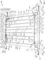
- a knock down gate assembly 100 is shown in a disassembled state.
- the gate assembly 100 is formed from steel.
- the gate assembly 100 can be formed from any type of metal, e.g., aluminum, iron, etc.
- the gate assembly 100 can be formed from plastic, wood, other metals or metal alloys, combinations thereof, or any other alternative material. It is contemplated that the gate assembly 100 can be formed from any suitable material.
- the knock down gate assembly 100 comprises a gate 102 and a support assembly 104.
- the support assembly 104 comprises a first support 106, a second support 108, and a base 110, and the first support 106, the second support 108, and the base 110 are hollow. As illustrated in FIG.
- the first support 106 is substantially straight and vertical and comprises a first upper end 112 and a first lower end 114 adjacent the base 110.
- the second support 108 is substantially vertical and vertical and comprises a second upper end 116 and a second lower end 118.
- the first support 106 and the second support 108 comprise a generally rectangular cross-section.
- the first support 106 and the second support 108 may comprise a non-rectangular cross-section, e.g., circular, oval, square, elliptic, triangular, etc.
- the first upper end 112 of the first support 106 comprises a latch assembly 130 thereon.
- the latch assembly 130 is configured to interact with an opening mechanism or handle assembly 132 to secure the gate assembly 100 in a closed state.
- the latch assembly 130 comprises a latch housing 134 having a first ribbed surface 136 and a protrusion 138 extending outwardly from the latch housing 134 below the first ribbed surface 136.
- the protrusion 138 comprises a generally triangular cross section. In some embodiments, the protrusion 138 may have a square, rectangular, circular, or oval cross-section. As will be discussed in further detail below, the protrusion 138 acts as a key to secure the handle assembly 132 to the latch assembly 130 (see FIGS.
- the latch assembly 130 also comprises a first upper housing 140 protruding out from a side of the first support 106, opposite the gate 102.
- the first upper housing 140 defines a first upper slot 142 having a rectangular cross-section.
- the first upper slot 142 extends into the latch assembly 130 of the first support 106.
- the first support 106 also comprises a first support aperture 150 that extends through the side of the first support 106, opposite the gate 102 (see FIG. 5 ).
- the first support aperture 150 is configured to align with a first base aperture 152 on the base 110 and receive a first support fastener 154 therethrough.
- the first support fastener 154 is configured to secure the first support 106 to the base 110.
- the second upper end 116 of the second support 108 comprises a mounting assembly 160 thereon.
- the mounting assembly 160 is configured to secure the gate 102 to the support assembly 104.
- the mounting assembly 160 comprises a mounting housing 162 having a ledge 164 that extends outwardly on a side of the second support 108 facing the gate 102.
- the ledge 164 comprises a mounting sleeve 166 extending upwardly therefrom.
- the mounting sleeve 166 is generally cylindrical and comprises a passageway 168 therethrough, and the mounting sleeve 166 comprises two sleeve protrusions or tips 170 extending from a top edge of the mounting sleeve 166 on diametrically opposed sides of the mounting sleeve 166 (only one tip 170 shown in FIG. 1 ). Further, the mounting sleeve 166 comprises a radial flange (not shown) extending within the passageway 168 of the mounting sleeve 166.
- the gate 102 is configured to be secured on the mounting sleeve 166, and the mounting sleeve 166 allows the gate 102 to rotate about the support assembly 104.
- the sleeve protrusions or tips 170 assist with the rotation of the gate 102 when the gate 102 is secured to the support assembly 104, i.e., the tips 170 act as a bearing for the gate 102 to rotate on.
- the mounting assembly 160 also comprises a spring 172, a washer 174, and a mounting fastener 176 therein that assists with securing the gate 102 to the mounting assembly 160.
- the mounting assembly 160 also comprises a second upper housing 178 protruding out from a side of the mounting assembly 160 opposite the gate 102.
- the second upper housing 178 defines a second upper slot 180 having a rectangular cross-section.
- the second upper slot 180 extends into the mounting housing 162 of the second support 108. Similar to the first support 106, the second support 108 also comprises a second support aperture 182 that extends through a side of the second support 108, opposite the gate 102. The second support aperture 182 is configured to align with a second base aperture 184 on the base 110 and receive a second support fastener 186 therethrough. The second support fastener 186 is configured to secure the second support 108 to the base 110.
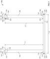
- the base 110 extends along the bottom of the gate assembly 100 and comprises a first end 202 adjacent the first support 106 and a second end 204 adjacent the second support 108. As illustrated in FIG. 1 , the base 110 is substantially straight and extends horizontally along the bottom of the gate assembly 100 (see FIG. 6 ). During use, the base 110 is positioned on the floor, ground, or a staircase. Similar to the first support 106 and the second support 108, the base 110 comprises a rectangular cross-section. However, in some embodiments, the base 110 can include a square, circular, oval, triangular, or irregular cross-section. As further illustrated in FIG.
- the base 110 comprises a first flange 206 adjacent the first end 202 of the base 110 and a second flange 208 adjacent the second end 204 of the base.
- the first flange 206 comprises a U-shaped cross-section defining a first channel 210 therein.
- the second flange 208 also comprises a U-shaped cross-section defining a second channel 212 therein.
- the first flange 206 and the second flange 208 may comprise a rectangular cross-section.
- the first flange 206 comprises the first base aperture 152 extending therethrough.
- the second flange 208 comprises the second base aperture 184 extending therethrough.
- the first base aperture 152 and the second base aperture 184 only extend through one side of the flange 206, 208, i.e., the side opposite the gate 102.
- the first base aperture 152 and the second base aperture 184 extend through both sides of the first flange 206 and the second flange 208, respectively.
- the first flange 206 and the second flange 208 are welded to the base 110. However, it is contemplated that the first flange 206 and the second flange 208 can be secured to the base 110 in any known fastening way.
- the first end 202 of the base 110 comprises a first lower housing 216 defining a first lower slot 218.
- the first lower slot 218 comprises a rectangular cross section.
- the second end 204 of the base 110 comprises a second lower housing 220 defining a second lower slot 222.
- the second lower slot 222 also comprises a rectangular cross section.
- the first lower slot 218 and the second lower slot 222 are similar to the first upper slot 142 and the second upper slot 180.
- the base 110 comprises a gate aperture 224 adjacent the second flange 208 ( FIG. 5 ).
- the gate aperture 224 extends through a side of the base 110 that faces the gate 102.
- the gate aperture 224 is configured to receive a portion of the gate 102 therein.
- the gate aperture 224 only extends through one side of the base 110.
- the first support 106 comprises a length L1
- the second support 108 comprises a length L2
- the base 110 comprises a length L3.
- the first flange 206 of the base 110 comprises a length L4
- the second flange 208 of the base 110 comprises a length L5.
- the length L1 and the length L2 may be equal.
- the length L1 may be greater or smaller than the length L2.
- the length L4 can be equal to the length L5.
- the length L4 may be greater or smaller than the length L5.
- the length L1 and the length L2 are between about 15" (38 cm) and about 70" (178 cm), or about 15" (38 cm) and about 50" (127 cm), or about 20" (51 cm) and about 30" (76 cm), or about 28.25" (72 cm), or at least 15" (38 cm), or at least 20" (51 cm), or at least 25" (64 cm).
- the length L3 is between about 15" (38 cm) and about 70" (178 cm), or about 15" (38 cm) and about 50" (127 cm), or about 20" (51 cm) and about 30" (76 cm), or about 27.5" (70 cm), or at least 15" (38 cm), or at least 20" (51 cm), or at least 25" (64 cm).
- the length L4 and the length L5 are between about 0.1" (0.3 cm) and about 25" (64 cm), or about 1" (2.5 cm) and about 10" (25 cm), or about 2" (5 cm) and about 3" (7.6 cm), or about 2.6" (6.7 cm), or about 2.75" (7 cm), or at least 0.1" (0.25 cm), or at least 1" (2.5 cm), or at least 2" (5.1 cm), or at least 3" (7.6 cm).
- a ratio between the length L4 and the length L3 is between about 0.01 and about 0.5, or about 0.05 and about 0.02, or about 0.05 and about 0.15, or about 0.08 and about 0.12, or about 0.09 and about 0.11, or about 0.09, or about 0.1, or at least 0.01, or at least 0.05, or at least 0.09, or at least 0.1.
- a ratio between the length L5 and the length L3 is between about 0.01 and about 0.5, or about 0.05 and about 0.02, or about 0.05 and about 0.15, or about 0.08 and about 0.12, or about 0.09 and about 0.11, or about 0.09, or about 0.1, or at least 0.01, or at least 0.05, or at least 0.09, or at least 0.1.
- a ratio between the length L4 and the length L1 is between about 0.01 and about 0.5, or about 0.04 and about 0.2, or about 0.05 and about 0.15, or about 0.09 and about 0.11, or about 0.09 and about 0.1, or about .09, or about .1, or at least 0.01, or at least 0.04, or at least 0.05, or at least 0.09, or at least 0.1.
- a ratio between the length L5 and the length L2 is between about 0.01 and about 0.5, or about 0.04 and about 0.2, or about 0.05 and about 0.15, or about 0.09 and about 0.11, or about 0.09 and about 0.1, or about .09, or about .1, or at least 0.01, or at least 0.04, or at least 0.05, or at least 0.09, or at least 0.1.
- a ratio between the length L3 and the length L1 is between about 0.4 and about 1.5, or about 0.6 and about 1.1, or about 0.9 and about 1.0, or about 0.95, or at least .4, or at least 0.6, or at least 0.8, or at least 0.9, or at least 1.0.
- a ratio between the length L3 and the length L2 is between about 0.4 and about 1.5, or about 0.6 and about 1.1, or about 0.9 and about 1.0, or about 0.95, or at least .4, or at least 0.6, or at least 0.8, or at least 0.9, or at least 1.0.
- the gate 102 comprises an upper rail 250 and a lower rail 252.
- the upper rail 250 and the lower rail 252 are disposed at opposing ends of the gate 102, and each includes a plurality of post receiving apertures 254.
- the post receiving apertures 254 are sized and shaped to receive ends of a plurality of posts 256, which are generally disposed orthogonally with respect to the upper rail 250 and the lower rail 252.
- the plurality of posts 256 may comprise a plurality of fastening posts 258 and a plurality of cylindrical posts 260.
- the upper rail 250, the lower rail 252, and the plurality of posts 256 are substantially hollow.
- a first and second cylindrical post 260a, 260b are disposed at a far-left side of the gate 102, and a third cylindrical post 260c is disposed between the plurality of fastening posts 258.
- the plurality of cylindrical posts 260 aid in assembly of the gate 102, as discussed in greater detail hereinafter below.
- the plurality of cylindrical posts 260 are inserted into the post receiving apertures 254 that are the same size as the post receiving apertures 254 that receive the fastening posts 258.
- the gate 102 comprises three cylindrical posts 260 and four fastening posts 258.
- the gate 102 can comprise any number of cylindrical posts 260 and/or fastening posts 258.
- the third cylindrical post 260c may be a fastening post 258 or all of the posts may be cylindrical posts 260c or fastening posts 258.
- a plurality of post fasteners 262 are shown, which may be bolts, screws, or other fasteners known to those of ordinary skill in the art.
- the post fasteners 262 may be inserted into the upper rail 250 and the lower rail 252, and engage with the fastening posts 258.
- the gate 102 comprises four fastening posts 258 that engage with the post fasteners 262.
- the gate 102 may comprise more or fewer fastening posts 258.
- the plurality of cylindrical posts 260 are not fastened to the rails 250, 252; rather, upper and lower ends of the plurality of cylindrical posts 260 are retained within the post receiving apertures 254 when the rails 250, 252 are fastened to the plurality of fastening posts 258.
- more or all of the plurality of cylindrical posts 260 are constructed as fastening posts 258, and are rigidly fastened to the rails 250, 252 via the post fasteners 262, adhesive, or another means of fastening.
- the fastening posts 258 may comprise the same diameter as the cylindrical posts 260.
- the sizes of the post receiving apertures 254 are consistent to snugly or fittingly receive whichever of the plurality of posts 256 is being inserted into each post receiving aperture 254.
- the diameters of the plurality of posts 256 are the same in the present embodiment, it is contemplated that alternative diameters of the plurality of posts 256 may be practiced.
- alternative post configurations are also contemplated, and the plurality of posts 256 may have other, non-circular cross sections or cross-sections that vary in diameter along a length of the plurality of posts 256.
- one or more of the posts 256 may have a wave-like pattern along a length thereof.
- the plurality of cylindrical posts 260 may comprise a first diameter and the plurality of fastening posts 258 may comprise a second diameter, different than the first diameter, i.e., the plurality of fastening posts 258 may have a larger diameter or a smaller diameter than the plurality of cylindrical posts 260.
- the plurality of fastening posts 258 and the plurality of cylindrical posts 260 have the same vertical length, i.e., vertical direction in FIG. 2 .
- the plurality of fastening posts 258 may be shorter or taller than the plurality of cylindrical posts 260.
- the plurality of cylindrical posts 260 may be shorter than the plurality of fastening posts 258, allowing hardware to be inserted into the horizontal upper and lower rails 250, 252 into the spaces in-line with the plurality of cylindrical posts 260.
- the plurality of fastening posts 258 may be formed with internal threading to allow the post fasteners 262 to engage with the plurality of fastening posts 258, which thereby retains the plurality of fastening posts 258 with the rails 250, 252.
- the internal threading may be formed directly on an internal surface of the plurality of fastening posts 258.
- the internal threading may be achieved by welding, adhering, or otherwise coupling a threaded nut into one or both of the upper and lower ends of the plurality of fastening posts 258.
- the plurality of cylindrical posts 260 are placed inside of the frame and "sandwiched" by the rails 250, 252.
- the gate 102 is preferably disposed in an orientation similar to that shown in FIG. 1 immediately before fastening and assembling the various components.
- the upper rail 250 comprises a first upper rail end 264 and a second upper rail end 266, opposite the first upper rail end 264.
- the opening mechanism or handle assembly 132 is positioned on the first upper rail end 264 of the upper rail 250.
- the handle assembly 132 comprises a handle housing 272 and a handle sleeve 274.
- the handle sleeve 274 comprises a grip 276 thereon.
- the handle sleeve 274 is configured to rotate about the handle housing 272 between a first configuration (see FIG. 1 ), i.e., closed position, and a second configuration (see FIG. 8 ), i.e., open position.
- a first configuration see FIG. 1
- a second configuration see FIG. 8
- the handle assembly 132 comprises a button 278 on both sides of the handle assembly 132 (only one button 278 is illustrated).
- the button 278 is configured to allow the handle sleeve 274 to move between the first configuration and the second configuration, i.e., a user presses both buttons 278 on both sides to move the handle sleeve 274 from the first configuration to the second configuration.
- the handle housing 272 further comprises an arm 280 extending outwardly therefrom.
- the arm 280 extends outwardly from the left side of the handle housing 272 and comprises an arm slot 282 (see FIG. 8 ) on both sides of the arm 280 (only one arm slot 282 shown in FIG. 8 ) and an arm wall 284.
- the arm slots 282 interact with internal cams (not shown) within the handle sleeve 274.
- the arm slots 282 and the internal cams (not shown) are configurated such that the handle sleeve 274 linearly translates the arm wall 284, away from the handle housing 272, while the handle sleeve 274 rotates about the handle housing 272. Therefore, the arm wall 284 is configurated to horizontally translate between a first configuration and a second configuration, depending on the first and second configuration of the handle sleeve 274.
- the arm wall 284 comprises a second ribbed surface 286 and a groove 288 positioned below the second ribbed surface 286.
- the groove 288 has a generally triangular shape with an opening at the bottom.
- the groove 288 is configurated to mate with the protrusion 138 on the latch assembly 130 to lock the gate 102 in place on the support assembly 104.
- the handle sleeve 274 comprises a sidewall 290 having an edge 292 with various splines and curves therein.
- the sidewall 290 comprises a concave and convex edge.
- the upper rail 250 comprises an upper pin assembly 310 on the second upper rail end 266.
- the upper pin assembly 310 comprises an upper pin housing 312 having a pin sleeve 314.
- the pin sleeve 314 is generally cylindrical and defines a pin chamber 316.
- An upper pin 318 extends through the pin chamber 316 and is also substantially cylindrical.
- the upper pin 318 is configured to extend into the mounting sleeve 166 on the mounting assembly 160 of the second support 108.
- the upper pin 318 extends into the passageway 168 of the mounting sleeve 166, between the radial flange (not shown) of the mounting sleeve 166.
- the mounting sleeve 166 is positioned within the pin chamber 316 of the pin sleeve 314. Therefore, as illustrated in FIG. 6 , once assembled, the mounting sleeve 166 is substantially or completely covered by the upper pin housing 312, i.e., the pin sleeve 314.
- the lower rail 252 comprises a first lower rail end 322 and a second lower rail end 324.
- the lower rail 252 comprises a clamp assembly 330 positioned on the first lower rail end 322 of the lower rail 252.
- the clamp assembly 330 comprises a clamp housing 332 and a clamp 334 extending from the clamp housing 332.
- the clamp 334 is configured to secure to or on the side of the base 110 facing the gate 102 (see FIG. 6 ).
- the clamp 334 allows the gate 102 to be secured to the base 110 when the gate 102 is in the closed configuration, i.e. , the handle assembly 132 is secured on the latch assembly 130.
- the lower rail 252 further comprises a lower pin assembly 340 positioned on the second lower rail end 324 of the lower rail 252.
- the lower pin assembly 340 comprises a lower pin housing 342 and a lower pin 344 extending from the lower pin housing 342.
- the lower pin 344 is formed from steel.
- the lower pin 344 may be formed from another metal or from plastic.
- the lower pin 344 is configured to be inserted through the gate aperture 224 in the base 110. Therefore, the gate 102 is configured to rotate about the upper pin 318 and the lower pin 344 between the open position and the closed position.
- the latch assembly 130, the mounting assembly 160, the handle assembly 132, the upper pin assembly 310, the lower pin assembly 340, and the clamp assembly 330 are all formed from plastic, e.g., injection molding.
- the latch assembly 130, the mounting assembly 160, the handle assembly 132, the upper pin assembly 310, the lower pin assembly 340, and the clamp assembly 330 may be formed from metal, e.g., steel, aluminum, etc. (see FIGS. 10-13 ).
- the gate assembly 100 further includes a plurality of spindle assemblies 360.
- the plurality of spindle assemblies 360 include a first upper spindle assembly 360a, a first lower spindle assembly 360b, a second upper spindle assembly 360c, and a second lower spindle assembly 360d.
- Each of the plurality of spindle assemblies 360 comprises a nut 362 and a threaded portion 364 attached to a latch or head portion 366.
- the head 366 of the first upper spindle assembly 360a and the second upper spindle assembly 360c is substantially circular while the head 366 of the first lower spindle assembly 360b and the second lower spindle assembly 360d comprises a half circle or three-fourths circle such that it can be placed on the ground or floor. As illustrated in FIG.
- the threaded portion 364 of the first upper spindle assembly 360a is configured to be inserted into the first upper slot 142 of the first upper housing 140
- the threaded portion 364 of the second upper spindle assembly 360c is configured to be inserted into the second upper slot 180 of the second upper housing 178
- the threaded portion 364 of the first lower spindle assembly 360b is configured to be inserted into the first lower slot 218 of the first lower housing 216
- the threaded portion 364 of the second lower spindle assembly 360d is configured to be inserted into the second lower slot 222 of the second lower housing 220.
- the plurality of spindle assemblies 360 are configured to secure onto a door frame or wall of an opening.
- the heads 366 of the plurality of spindle assemblies 360 may comprise a plastic covering in order to limit scratches on the door frame or wall.
- spindle housings (not shown) may be added within the first upper slot 142, the second upper slot 180, the first lower slot 218, and the second lower slot 222 before the plurality of spindle assemblies 360 are respectively added therein.
- Alternative configurations of the plurality of spindle assemblies 360 are contemplated.
- the plurality of spindle assemblies 360 may be similar to the spindle assemblies disclosed in U.S. Patent No. 11,118,398 .
- Alternative spindle assemblies may also be utilized, depending on the desired functionality of the gate assembly 100.
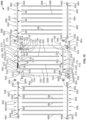
- the knock down gate assembly 100 is shown in a disassembled state with a plurality of extension assemblies 380.
- the plurality of extension assemblies 380 may be added to the gate assembly 100 to increase the total width of the gate assembly 100.
- the left side of the gate assembly 100 comprises a first extension assembly 380a and the right side of the gate assembly 100 comprises a second extension assembly 380b.
- only one side of the gate assembly 100 may comprise the extension assembly 380.
- multiple extension assemblies 380 may be added to each side of the gate assembly 100.
- each of the plurality of extension assemblies 380 comprises an upper coupler 382, a lower coupler 384, an extension post 386, an upper extension housing 388, and a lower extension housing 390.
- the upper coupler 382 and the lower coupler 384 are substantially the same and are formed from metal, i.e., steel. Further, the upper coupler 382 and the lower coupler 384 are hollow and form a general rectangular prism. As illustrated in FIG. 2 , the upper coupler 382 is configured to be inserted into the first upper slot 142 and/or the second upper slot 180. Similarly, the lower coupler 384 is configured to be inserted into the first lower slot 218 and the second lower slot 222.
- the upper extension housings 388 and the lower extension housings 390 each comprises a housing portion 392 and a cylindrical portion 394 extending orthogonal to the housing portion 392.
- the housing portions 392 are hollow and comprise a rectangular cross section that matches the shape of the upper coupler 382 and the lower coupler 384.
- each of the housing portions 392 comprise an extension passageway 396 extending therethrough.
- the cylindrical portions 394 are also hollow and each comprises an extension cavity 398 therein.
- the extension cavities 398 do not connect with the extension passageways 396. Instead, the extension cavities 398 are configured to receive and retain the extension posts 386.
- each of the lower extension housings 390 comprise an extension flange 402 extending from a bottom (with reference to FIG. 2 ) of the housing portions 392.
- the extension flanges 402 make contact with the floor or ground and level the lower extension housings 390 such that the extension cavity 398 is aligned with the first and second lower slots 218, 222. Therefore, once the upper couplers 382 and the lower couplers 384 are secured within the first and second upper slots 142, 180 and the first and second lower slots 218, 222, respectively, the upper extension housings 388 and the lower extension housings 390 can slide on the remaining portion of the upper and lower couplers 382, 384 that extend outwardly from the support assembly 104.
- the extension posts 386 extend between the cylindrical portions 394 of the upper and lower extension housings 388, 390.
- the extension posts 386 are made of metal and are similar to the fastening posts 258 and/or the cylindrical posts 260 described above.
- the extension posts 386 have the same vertical length as the fastening posts 258 and the cylindrical posts 260.
- the extension posts 386 can have a longer or shorter vertical length than the fastening posts 258 and/or the cylindrical posts 260.
- the extension posts 386 comprise a larger diameter than the fastening posts 258 and the cylindrical posts 260.
- the extension posts 386 may comprise the same diameter as the fastening posts 258 and/or the cylindrical posts 260. During use, the extension posts 386 are configured to snuggly fit within the extension passageways 396 of the cylindrical portions 394 of the upper and lower extension housings 388, 390.
- the plurality of spindle assemblies 360 are configured to slide into the hollow portions of the upper couplers 382 and the lower couplers 384, which, during use, are secured partially within the first and second upper slots 142, 180 and the first and second lower slots 218, 222 and partially within the upper and lower extension housings 388, 390 (see FIG. 8 ). Therefore, approximately half of each coupler 382, 384 is secured within the slots 142, 180, 218, 222 of the support assembly 104 and the other half of each coupler 382, 384 is secured within the extension passageways 396 of the of the upper and lower extension housings 388, 390.
- first upper slot 142, the second upper slot 180, the first lower slot 218, and the second lower slot 222 may comprise a stop therein that limits the upper and lower couplers 382, 384 from sliding too deep within the slots 142, 180, 218, 222.
- approximately half of each upper and lower coupler 382, 384, should be seen extending outwardly from each of the slots 142, 180, 218, 222 after the upper and lower couplers 382, 384 are slid into the slots 142, 180, 218, 222.
- one of the plurality of extension assemblies 380 can add about 2.75" (7 cm) to the width of the gate assembly 100. In some embodiments, one of the plurality of extension assemblies 380 can add between about 1" (2.5 cm) and about 4" (10 cm) or between about 2" (5 cm) and about 3" (7.6 cm) to the width of the gate assembly 100. In some embodiments, one of the plurality of extension assemblies 380 can add at least 1" (2.5 cm) or at least 2" (5 cm) to the width of the gate assembly 100.
- first support 106 should be aligned with the first flange 206 of the base 110 and the second support 108 should be aligned with the second flange 208 of the base 110.
- the first support 106 and the second support 108 should be then urged onto the first and second flanges 206, 208 of the base 110, respectively.
- the first and second flanges 206, 208 are configured to be slidingly retained within the hollow space of the first and second supports 106, 108, respectively.
- the first support aperture 150 of the first support 106 and the first base aperture 152 of the base 110 should be aligned to receive the first support fastener 154.
- the second support aperture 182 of the second support 108 and the second base aperture 184 of the base 110 should be aligned to receive the second support fastener 186.
- the support assembly 104 is illustrated in an assembled state. As illustrated in FIG. 3 , the first support 106 and the second support 108 completely cover the first flange 206 and the second flange 208, respectively.
- the first and second supports 106, 108 are orthogonal to the base 110 once assembled, i.e., the first support 106 and the second support 108 are substantially parallel.
- the first and second supports 106, 108 may comprise an angle greater than 90° with the base 110, i.e., the first support 106 and the second support 108 diverge from one another.
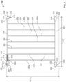
- the upper rail 250 of the gate 102 should be positioned in a parallel fashion with the lower rail 252 of the gate 102 such that the post receiving apertures 254 are aligned.
- the fastening posts 258 should be aligned within their respective post receiving apertures 254, and the post fasteners 262 may be inserted into fastener apertures 410 along the upper and lower rails 250, 252, although the post fasteners 262 preferably are not tightened at this stage in order to leave sufficient clearance to install the plurality of cylindrical posts 260.
- the plurality of cylindrical posts 260 are aligned with the respective post receiving apertures 254 in a fashion similar to the configuration shown in FIGS. 1 and 2 .
- the post fasteners 262 which in the present embodiment are machine screws, are either inserted into the fastener apertures 410 and are tightened or already having been inserted into the fastener aperture 410 are simply tightened. Tightening of the post fasteners 262 draws the upper rail 250 and the lower rail 252 closer together, and retains the plurality of cylindrical posts 260 within the post receiving apertures 254.
- the gate 102 is illustrated in an assembled state.
- the plurality of posts 256 are securely fastened to the upper and lower rail 250, 252.
- the plurality of posts 256 are substantially orthogonal with the upper and lower rails 250, 252.
- the plurality of posts 256 may be slightly angled with respect to the upper and lower rails 250, 252.
- the gate 102 and the support assembly 104 are shown assembled and in an exploded view. As illustrated in FIGS. 1-5 , once the gate 102 and the support assembly 104 are assembled, the gate 102 can be attached to the support assembly 104. In particular, the gate 102 is placed on the support assembly 104 such that the upper pin 318 of the upper pin assembly 310 is aligned with the passageway 168 of the mounting assembly 160, i.e., the mounting sleeve 166 is positioned within the pin chamber 316, and the lower pin 344 of the lower pin assembly 340 is aligned with the gate aperture 224 of the base 110.
- the upper pin 318 of the upper pin assembly 310 is then urged into the passageway 168 of the mounting assembly 160 and the lower pin 344 of the lower pin assembly 340 is urged into the gate aperture 224 of the base 110 to secure the gate 102 to the support assembly 104.
- the upper pin assembly 310 is positioned on the ledge 164 of the mounting assembly 160 and the lower pin assembly 340 is positioned on the base 110.
- the gate 102 is rotatable about the support assembly 104. Specifically, the upper pin 318 and the lower pin 344 create an axis of rotation that the gate 102 can rotate by.
- the upper pin 318 is capable of rotating while positioned within the passageway 168 of the mounting assembly 160 and the lower pin 344 is capable of rotating while positioned within the gate aperture 224 of the base 110.
- the spring 172, the washer 174, and the mounting fastener 176 may be secured within the mounting assembly 160 before or after the gate 102 is secured to the support assembly 104.
- the plurality of spindle assemblies 360 may be secured within the slots 142, 180, 218, 222 of the support assembly 104 and adjusted depending on the width of the opening that the gate assembly 100 is intended to span, as described in greater detail below.
- the gate assembly 100 may be placed in an open or closed position.
- the open position is defined as any position in which the handle assembly 132 is not attached or secured to the latch assembly 130 on the first support 106 and access through the gate assembly 100 is allowed.
- the closed position is defined as a position when the handle assembly 132 is secured to the latch assembly 130 on the first support 106 and access through the gate assembly 100 is not allowed. The user should not be able to walk through the support assembly 104 when the gate 102 is in the closed position.
- the gate assembly 100 cannot be placed in a closed position until the gate assembly 100 has been secured within the opening. Therefore, in some embodiments, a small gap may exist between the arm 280 of the handle assembly 132 and the latch assembly 130 until the gate assembly 100 is tightly secured within the opening.
- the gate assembly 100 is installed in a structurally sound opening.
- the gate assembly 100 may be secured to a staircase opening.
- the plurality of spindle assemblies 360 should be secured within the support assembly 104.
- the threaded portion 364 of the first upper spindle assembly 360a should be inserted into the first upper slot 142 of the first upper housing 140
- the threaded portion 364 of the second upper spindle assembly 360c should be inserted into the second upper slot 180 of the second upper housing 178
- the threaded portion 364 of the first lower spindle assembly 360b should be inserted into the first lower slot 218 of the first lower housing 216
- the threaded portion 364 of the second lower spindle assembly 360d should be inserted into the second lower slot 222 of the second lower housing 220.
- the threaded portions 364 of the plurality of spindle assemblies 360 may be fastened within the slots 142, 180, 218, 222.
- the threaded portions 364 of the plurality of spindle assemblies 360 may snap fit or slidingly engage with the slots 142, 180, 218, 222 to secure the plurality of spindle assemblies 360 therein. Furthermore, in some embodiments, the threaded portions 364 may be simply inserted within the slots 142, 180, 218, 222 and secured thereto.
- the gate assembly 100 should be placed within the opening it is intended to occupy. An appropriate width may be achieved by adjusting one or more of the four spindle assemblies 360a, 360b, 360c, 360d. Each of the plurality of spindle assemblies 360 is capable of adjustment individually, and may be extended to varying lengths to allow for molding, uneven walls, etc.
- the nuts 362 can be rotated along the threaded portions 364 of the plurality of spindle assemblies 360 to increase the length that the plurality of spindle assemblies 360 extend from the support assembly 104. Therefore, the plurality of spindle assemblies 360 should be adjusted until a desired width is achieved. It is preferred that the gate assembly 100 be secured tightly to the opening in order for the gate assembly 100 to achieve optimal performance.
- the gate assembly 100 is illustrated in an installed state, attached to a door opening in the closed position, i.e., the user cannot walk through the gate assembly 100.
- the handle assembly 132 is secured to the latch assembly 130 and the handle sleeve 274 is in the first configuration.
- the arm wall 284 of the arm 280 of the handle assembly 132 is positioned against the latch assembly 130 on the first support 106.
- the protrusion 138 on the latch assembly 130 is secured within the groove 288 on the arm wall 284, and the first ribbed surface 136 of the latch assembly 130 is in contact with the second ribbed surface 286 of the arm wall 284 in order to secure the handle assembly 132 to the latch assembly 130.
- the arm wall 284 is pressed firmly against the latch assembly 130 in order to apply additional pressure to gate assembly 100 and further lock the gate assembly 100 to the walls of the opening. This additional pressure helps to further secure the support assembly 104 to the opening, causing the gate assembly 100 to be sturdier within the opening.
- the clamp 334 of the clamp assembly 330 secures the bottom of the gate 102 to the base 110 of the support assembly 104. Further, incremental changes in how far the plurality of spindle assemblies 360 are spaced from the support assembly 104 can be made at any time by adjusting the nuts 362 to increase and/or decrease the tension.
- the user in order to open the gate assembly 100, the user should press the buttons 278 on the handle assembly 132 and rotate the handle sleeve 274 of the handle assembly 132 to the second configuration (see FIG. 8 ).
- rotation of the handle sleeve 274 causes the arm wall 284 to linearly translate toward or away from the gate 102. Therefore, as the user rotates the handle sleeve 274 to the second configuration, the arm wall 284 of the arm 280 will move away from the latch assembly 130.
- the handle sleeve 274 is shown in the second configuration and a gap 432 exists between the arm wall 284 of the arm 280 and the latch assembly 130.
- the user should lift the handle assembly 132, thereby lifting the gate 102, upward in the direction of arrow A and rotate the gate 102 to allow access through the gate assembly 100. It is necessary to lift the gate 102 in order to remove the protrusion 138 of the latch assembly 130 from the groove 288 of the arm wall 284 via the opening at the bottom. Further, lifting the gate 102 allows the clamp 334 to be disconnected from the base 110 of the support assembly 104.
- the gate assembly 100 can include various closing mechanisms or handles to secure the gate 102 to the support assembly 104 in the closed configuration.
- the handle assembly 132 may comprise a sliding tab that locks to gate 102 to the support assembly 104 (see FIG. 13 ).
- the gate assembly 100 is illustrated with the plurality of extension assemblies 380.
- the first extension assembly 380a and the second extension assembly 380b are secured on respective sides of the gate assembly 100 in order to increase the overall width of the gate assembly 100.
- FIGS. 2 , 7 , and 8 a method of assembling the plurality of extension assemblies 380 to the gate assembly 100 will now be described.
- the plurality of extension assemblies 380 can be attached thereto.
- the plurality of extension assemblies 380 can be attached to the support assembly 104 before the gate 102 is attached thereto.
- the upper couplers 382 of the extension assemblies 380 should be inserted into the first and second upper slots 142, 180 and the lower couplers 384 of the plurality of extension assemblies 380 should be inserted into the first and second lower slots 218, 222.
- the plurality of spindle assemblies 360 should be inserted into the hollow portions of the upper and lower couplers 382, 384, i.e., into the upper and lower extension housings 388, 390 (see FIG. 7 ).
- the gate assembly 100 can then be secured to the opening in a similar manner as outlined above, i.e., adjusting the plurality of spindle assemblies 360 to achieve the appropriate width.
- multiple extension assemblies 380 may be attached to both sides or one side of the support assembly 104. Further, in some embodiments, an additional gate or a full gate panel may be secured to the sides of the support assembly 104 instead of the extension assemblies 380 (see FIGS. 10-13 ).
- the new packaging 450 is designed to efficiently hold the gate assembly 100 therein. Therefore, the new packaging 450 is designed to hold the gate assembly 100 when it is disassembled, i.e., in a state similar to FIG. 1 . Once disassembled, all of the components of the gate assembly 100 can be bundled together and put in the new packaging 450.
- the first support 106, the second support 108, the base 110, the upper rail 250, the lower rail 252, and the plurality of posts 256 may be configured to extend substantially parallel to each other in the new packaging 450.
- the new packaging 450 may define a kit for the knock down gate assembly 100.
- the new packaging 450 defines a width of the packaging WP, a height of the packaging HP, and a depth of the packaging DP.
- the gate assembly 100 when fully assembled and installed, defines a width of the gate assembly WG, a height of the gate assembly HG, and a depth of the gate assembly DG (see FIG. 5 ).
- the gate 102 defines a width of the gate WF, a height of the gate HF, and a depth of the gate DF (see FIG. 5 ).
- the width of the packaging WP may be a first packaging dimension
- the height of the packaging HP may be a second packaging dimension
- the depth of the packaging DP may be a third packaging dimension.
- the width of the gate WF may be a first gate dimension
- the height of the gate HF may be a second gate dimension
- the depth of the gate DF may be a third gate dimension.
- the width of the gate assembly WG may be a first gate assembly dimension
- the height of the gate assembly HG may be a second gate assembly dimension
- the depth of the gate assembly DG may be a third gate assembly dimension.
- the first packaging dimension is less than the respective first gate assembly dimension, as shown in the Figures.
- the first, second, and third dimensions of the new packaging 450, gate 102, and/or gate assembly 100 may be rearranged, and need not be limited to the specific structure recited above.
- the new packaging 450 has at least one dimension, i.e., the width of the packaging WP, the height of the packaging HP, or the depth of the packaging DP, that is less than at least one respective dimension of the gate assembly 100, i.e., the width of the gate assembly WG, the height of the gate assembly HG, or the depth of the gate assembly DG.
- at least two of the plurality of packing dimensions, i.e., the width of the packaging WP, the height of the packaging HP, or the depth of the packaging DP are smaller than at least two of the corresponding gate assembly dimensions, i.e., the width of the gate assembly WG, the height of the gate assembly HG, or the depth of the gate assembly DG.
- the width of the packaging WP is between about 5% and about 70% of the width of the gate assembly WG, or between about 10% and about 60% of the width of the gate assembly WG, or between about 15% and about 50% of the width of the gate assembly WG. In some embodiments, the width of the packaging WP is less than about 70% of the width of the gate assembly WG, or less than about 60% of the width of the gate assembly WG, or less than about 50% of the width of the gate assembly WG, or less than about 40% of the width of the gate assembly WG, or less than about 30% of the width of the gate assembly WG, or less than about 20% of the width of the gate assembly WG, or less than about 10% of the width of the gate assembly WG.
- the width of the packaging WP is about 10% of the width of the gate assembly WG. In some embodiments, the width of the packaging WP is about 20% of the width of the gate assembly WG. In some embodiments, the width of the packaging WP is about 25% of the width of the gate assembly WG. While the widths, heights, and depths of the new packaging 450 and the gate assembly 100 are specifically referred to in the figures, the dimensions may be re-organized, such that the width, height, and/or depth comprise different dimensions than those shown in the Figures.
- the new packaging 450 has at least one dimension, i.e., the width WP, the height of the packaging HP, or the depth of the packaging DP, that is less than at least one respective dimension of the gate 102, i.e., the width of the gate WF, the height of the gate HF, or the depth of the gate DF.
- at least two of the plurality of packing dimensions, i.e., the width of the packaging WP, the height of the packaging HP, or the depth of the packaging DP are smaller than at least two of the corresponding gate dimensions, i.e., the width of the gate WF, the height of the gate HF, or the depth of the gate DF.
- the width of the packaging WP is between about 5% and about 70% of the width of the gate WF, or between about 10% and about 60% of the width of the gate WF, or between about 15% and about 50% of the width of the gate WF. In some embodiments, the width of the packaging WP is less than about 70% of the width of the gate WF, or less than about 60% of the width of the gate WF, or less than about 50% of the width of the gate WF, or less than about 40% of the width of the gate WF, or less than about 30% of the width of the gate WF, or less than about 20% of the width of the gate WF, or less than about 10% of the width of the gate WF.
- the width of the packaging WP is about 10% of the width of the gate WF. In some embodiments, the width of the packaging WP is about 20% of the width of the gate WF. In some embodiments, the width of the packaging WP is about 30% of the width of the gate WF. While the widths, heights, and depths of the new packaging 450 and the gate 102 are specifically referred to in the figures, the dimensions may be re-organized, such that the width, height, and/or depth comprise different dimensions than those shown in the Figures.
- the width of the gate assembly WG is between about 15" (38 cm) and about 72" (183 cm), or about 20" (51 cm) and about 35" (89 cm), or about 25" (64 cm) and about 30" (76 cm), or about 28" (71 cm), or at least 15" (38 cm), or at least 20" (51 cm), or at least 25" (64 cm), or at least 28" (71 cm).
- the height of the gate assembly HG is between about 15" (38 cm) and about 72" (183 cm), or about 15" (38 cm) and about 50" (127 cm), or about 25" (64 cm) and about 35" (89 cm), or about 29.5" (75 cm), or at least 15" (38 cm), or at least 25" (64 cm), or at least 29.5" (75 cm).
- the width of the gate WF is between about 10" (25 cm) and about 72" (183 cm), or about 20" (51 cm) and about 35" (89 cm), or about 22.25” (57 cm), or at least 20" (51 cm), or at least 22.25” (57 cm).
- the height of the gate HF is between about 10" (25 cm) and about 72" (183 cm), or about 20" (51 cm) and about 30" (76 cm), or about 28.25” (72 cm), or at least 20" (51 cm), or at least 28.25” (72 cm).
- a gate assembly 100 that can be set up on site quickly and with relatively simple assembly, with a reduced shipping and storage profile, and with reduced shipping costs is provided.
- FIGS. 10-13 like reference numbers are used with regard to an alternative embodiment of a knock down gate assembly 600.
- the gate assembly 600 is similar to the gate assembly 100 except for a few differences, which will be explained in detail below.
- the gate assembly 600 is shown in a disassembled state. Similar to the gate assembly 100, the gate assembly 600 can be shipped to the user disassembled and then put together for use.
- the gate assembly 600 is also formed from steel; however, it is contemplated that the gate assembly 600 can be formed from any type of metal, metal alloy, plastic, wood, combinations thereof, or an alternative material, similar to the gate assembly 100.
- the gate assembly 600 comprises a main panel 602 and one or more of a first auxiliary panel 604 and a second auxiliary panel 606.
- the main panel 602 is similar to the gate assembly 100 described above.
- the main panel 602 comprises a support assembly 608 and a gate 610.
- the gate 610 comprises five fastening posts 258 secured to the upper rail 250 and the lower rail 252 and the gate 610 does not comprise any of the cylindrical posts 260. Therefore, all of the fastening posts 258 are secured by the post fasteners 262 except for the two leftmost fastening posts 258a, 258b on the gate 610 (reference specifically to FIG. 10 ).
- the upper ends of the two leftmost fastening posts 258a, 258b are snuggly fit within the post receiving apertures 254 in the upper rail 250. Since the upper rail 250 comprises an opening mechanism or handle assembly 620, the post fasteners 262 cannot extend therethrough. Therefore, the upper ends of the two leftmost fastening posts 258a, 258b on the gate 610 act in a similar manner as the cylindrical posts 260 described above. It is noted that the lower ends of the two leftmost fastening posts 258a, 258b are secured to the lower rail 252 by the post fasteners 262, similar as described above.
- FIG. 11 a zoomed in view of the main panel 602 is illustrated in assembled state. Similar to the handle assembly 132 in FIGS. 1-8 , the handle assembly 620 is positioned on the first upper rail end 264 of the upper rail 250. As illustrated in FIGS. 11 and 13 , the handle sleeve 274 of the handle assembly 620 is not configured to rotate. Instead, the handle assembly 620 comprises a sliding tab 622 that is secured to a latch 624 (see FIG. 12 ). The latch 624 of the handle assembly 620 is configured to interact with a catch 626 on the latch assembly 130 of the first support 106 to secure the gate 610 to the support assembly 608.
- the sliding tab 622 and the latch 624 may be biased to a closed position (see FIG. 12 ) by an internal spring (not shown). Therefore, the sliding tab 622 and the latch 624 can always be in the closed position and require a force to move into the open position to remove the latch 624 from the catch 626 (see FIG. 13 ).
- the handle assembly 620 also comprises a magnet 632 positioned in a magnet cavity 634 below the latch 624. The magnet 632 is configured to interact with a locking cavity 636 in the latch assembly 130 to further secure the handle assembly 620 to the latch assembly 130. In particular, in the closed position, the magnet 632 is attracted to the metal within the locking cavity 636 and slides therein. Put differently, in the closed position, the magnet 632 partially extends outwardly from the magnet cavity 634 and into the locking cavity 636 in the latch assembly 130 (by way of magnetic forces). This allows the handle assembly 620 to be locked in placed to the latch assembly 130.
- the lower rail 252 of the gate 610 does not comprise the clamp assembly 330. Instead, the lower rail 252 of the gate 610 comprises a gate pin 642 that extends from the first lower rail end 322 of the lower rail 252.
- the gate pin 642 is resiliently positioned on the first lower rail end 322 of the lower rail 252.
- the gate pin 642 is secured within the lower rail 252 by a spring (not shown) that keeps the gate pin 642 in an extended state. Therefore, the gate pin 642 is configured to move into the lower rail 252 when a force is applied to it. Once the force subsides, the gate pin 642 is configured to pop back out of the lower rail 252 to the positions shown in FIG. 13 .
- the gate pin 642 is configured to secure the lower end of the gate 610 to the support assembly 608.
- the support assembly 608 of the gate assembly 600 is substantially similar to the support assembly 104 of the gate assembly 100.
- the first support 106 of the support assembly 608 also comprises a bracket 652 near the first lower end 114 of the first support 106.
- the bracket 652 comprises a general U-shape and is fastened to the first support 106.
- the bracket 652 also comprises an outer chamfered wall 654 and a bracket cavity 656.
- the outer chamfered wall 654 is positioned on an upper portion of the bracket 652 and the bracket cavity 656 is positioned directly below the outer chamfered wall 654.
- the bracket cavity 656 comprises a generally elongated shape and an inner chamfered wall (not shown) at a top end of the bracket cavity 656.
- the bracket cavity 656 is configured to receive the gate pin 642 when the gate 610 is in the closed position.
- the outer chamfered wall 654 and the inner chamfered wall (not shown) are configured to move the gate pin 642 into the lower rail 252 in order for the gate pin 642 to be inserted and removed from the bracket cavity 656.
- the support assembly 608 of the main panel 602 of the gate assembly 600 also comprises a plurality of upper hinges 660 and a plurality of lower hinges 662 positioned on the corners of the support assembly 608.
- the latch assembly 130 and the first end 202 of the base 110 comprise the lower hinges 662
- the mounting assembly 160 and the second end 204 of the base 110 comprise the upper hinges 662.
- the plurality of upper hinges 660 comprise a rod 664 extending downwardly from the plurality of upper hinges 660
- the plurality of lower hinges 662 comprise a hinge aperture 668 therein (see FIG. 10 ).
- the plurality of upper hinges 660 and the plurality of lower hinges 662 are positioned at the corners of the main panel 602 and are configured to interact with other upper and lower hinges 660, 662 to secure the main panel 602 to the first auxiliary panel 604 and the second auxiliary panel 606. Therefore, the plurality of lower hinges 662 on the main panel 602 will attach with corresponding upper hinges 660 on the first auxiliary panel 604 and the plurality of upper hinges 660 on the main panel 602 will attach with corresponding lower hinges 662 on the second auxiliary panel 606. The attachment of the upper and lower hinges 660, 662 create a joint 680. As will be described in more detail below, each of the first auxiliary panel 604 and the second auxiliary panel 606 also comprise the plurality of upper hinges 660 and the plurality of lower hinges 662.
- the first auxiliary panel 604 and the second auxiliary panel 606 are shown next to the main panel 602. While the present embodiment includes two auxiliary panels 604, 606, the same reference numbers apply to like elements of each auxiliary panel 604, 606 as described hereinafter below. As such, only one auxiliary panel, i.e., the first auxiliary panel 604, is described and referred to herein, however, the auxiliary panels 604, 606 are identical, and the description of one relates to the description of the other. As illustrated in FIG. 10 , the first auxiliary panel 604 comprises an auxiliary upper rail 682 and an auxiliary lower rail 684.
- the auxiliary upper rail 682 and the auxiliary lower rail 684 are disposed at opposing ends of the first auxiliary panel 604, and each includes a plurality of auxiliary post receiving apertures 686.
- the plurality of auxiliary post receiving apertures 686 are sized and shaped to receive ends of a plurality of auxiliary posts 688, which are generally disposed orthogonally with respect to the auxiliary upper rail 682 and the auxiliary lower rail 684.
- the plurality of auxiliary posts 688 function in the same way as the plurality of fastening posts 258 described above.
- a plurality of auxiliary post fasteners 690 may be inserted into the auxiliary upper rail 682 and the auxiliary lower rail 684, and engage with the plurality of auxiliary posts 688, similarly as described below with respect to the post fasteners 262 and the plurality of fastening posts 258.
- some of the plurality of auxiliary posts 688 may not be attached to the auxiliary upper rail 682 and/or the auxiliary lower rail 684.
- one or more of the plurality of auxiliary posts 688 may be screwed or just inserted into the auxiliary upper rail 682 and/or the auxiliary lower rail 684 in a similar way as the plurality of cylindrical posts 260 described above.
- the auxiliary upper rail 682 comprises the upper hinge 660 on one side of the first auxiliary panel 604 and the lower hinge 662 on the other side of the auxiliary upper rail 682.
- the auxiliary lower rail 684 comprises the upper hinge 660 on one side of the auxiliary lower rail 684 and the lower hinge 662 on the other side of the auxiliary lower rail 684.
- the hinges 660, 662 on the first auxiliary panel 604 are the same as the ones on the main panel 602. Therefore, the plurality of upper hinges 660 on the first auxiliary panel 604 are secured with the plurality of lower hinges 662 on the main panel 602 to create the joints 680.
- the main panel 602 is configured to be assembled in the same way as the gate assembly 100.
- the first support 106 and the second support 108 are secured to the first and second flanges 206, 208 of the base 110, and the plurality of fastening posts 258 are securely fastened to the upper rail 250 and the lower rail 252 by the plurality of post fasteners 262.
- the gate 610 and the support assembly 608 are assembled, they are attached to each other in a similar fashion as outlined above with respect to the gate assembly 100, i.e., the upper pin assembly 310 secures to the mounting assembly 160 and the lower pin assembly 340 secures to the base 110.
- the auxiliary upper rail 682 of the first auxiliary panel 604 should be positioned in a parallel fashion with the auxiliary lower rail 684 of the first auxiliary panel 604 such that the auxiliary post receiving apertures 686 are aligned.
- the plurality of auxiliary posts 688 should be aligned within their respective auxiliary post receiving apertures 686, and the auxiliary post fasteners 690 may be inserted into auxiliary fastener apertures 692 along the auxiliary upper and lower rails 682, 684.
- the plurality of auxiliary posts 688 are aligned with their respective auxiliary post receiving apertures 686 in a fashion similar to the configuration shown in FIG. 10 .
- the auxiliary post fasteners 690 which in the present embodiment are machine screws, are inserted into the auxiliary fastener apertures 692 and are tightened. Tightening of the auxiliary post fasteners 690 draws the auxiliary upper rail 682 and the auxiliary lower rail 684 closer together.
- the second auxiliary panel 606 is assembled in a similar way as the auxiliary first panel 604 described above. Further, in preferred embodiments, the main panel 602, the first auxiliary panel 604, and the second auxiliary panel 606 may be formed/assembled separately and then attached thereafter. However, in some embodiments, the main panel 602, the first auxiliary panel 604, and the second auxiliary panel 606 may be formed and installed together.
- the main panel 602 may be secured to the first auxiliary panel 604 and the second auxiliary panel 606.
- the plurality of upper hinges 660 on the first auxiliary panel 604 are secured to the plurality of lower hinges 662 on the main panel 602 and the plurality of upper hinges 660 on the main panel are secured to the plurality of lower hinges 662 on the second auxiliary panel 606.
- the rods 664 of the plurality of upper hinges 660 are urged through the hinge apertures 668 of the plurality of lower hinges 662 to form the joints 680.
- a joint coupler 694 is inserted into the upper and lower hinges 660, 662.
- the joint coupler 694 is configured to lock the joint 680 in place once it is fully urged into the upper and lower hinges 660, 662.
- the gate assembly 600 is illustrated in an assembled state and installed configuration. As illustrated in FIG. 12 , the first and second auxiliary panels 604, 606 are attached to the main panel 602. As noted herein, the gate assembly 600 is configured to be used in large doorways, hallways, or staircases and can comprise additional auxiliary panels 604, 606. For example, the gate assembly can include 3, 4, 5, 6, 7, 8, 9, or more auxiliary panels 604, 606 all attached to the main panel 602. In some embodiments, the gate assembly 600 may include more than one main panel 602 with the gate 610 therein. Once the first and second auxiliary panels 604, 606 are secured to the main panel 602, a user may adjust and/or rotate the first and second auxiliary panels 604, 606 with respect to the main panel 602.
- the gate assembly 600 is rotatable about the joints 680.
- the joints 680 allow the first and second auxiliary panels 604, 606 to rotate about 360°.
- the joint couplers 694 allow and stop the rotation of the joints 680. Specifically, if the user would like to rearrange the gate assembly 600 or move the first and second auxiliary panels 604, 606 to a new configuration, the user can lift the joint couplers 694 up such that they are in an up position (see FIGS. 11 and 13 ). Once the joint couplers 694 are in an up position, the first and second auxiliary panels 604, 606 can rotate freely about the main panel 602.
- the user can urge the joint couplers 694 downwardly to lock the joints 680 in place, i.e., the first and second auxiliary panels 604, 606 cannot rotate about the main panel 602 once the joint couplers 694 are placed in a down position (see FIG. 12 ). Therefore, the joint couplers 694 allow the gate assembly 600 to be locked in place and not move or rotate while the gate assembly 600 is attached to the wall.
- first auxiliary panel 604 and/or the second auxiliary panel 606 may be attached to, secured to, or mounted to a wall or doorway.
- the upper and lower hinges 660, 662 that are not attached to the main panel 602 may be secured to a wall mount or device to secure the gate assembly 600 to the wall or opening.
- the first and second auxiliary panels 604, 606 may be secured and/or mounted to a wall in any conventional manner.
- the gate assembly 600 is shown in a closed configuration, i.e., access through the gate is now allowed.
- the sliding tab 622 should be slid away from the latch assembly 130, i.e., to the open position, in order to disengage the latch 624 of the handle assembly 620 with the catch 626, and the gate 610 should be lifted up from the ground or floor.
- the magnet 632 will be pulled out of the locking cavity 636 and retract back into the magnet cavity 634 (see FIG. 13 ).
- the gate pin 642 will retract into the first lower rail end 322 of the lower rail 252 as it slides along the inner chamfered wall (not shown) inside the bracket cavity 656 (see FIG. 11 ). Once the gate 610 is lifted, the gate 610 can be rotated to an open position such that access through the gate 610 is allowed. In order to close the gate 610, the above steps are reversed such that the gate 610 is rotated to the closed position and lifted up and onto the support assembly 608. In particular, the gate pin 642 will retract again as it extends along the outer chamfered wall 654 of the bracket 652 and secure within the bracket cavity 656.
- the sliding tab 622 should be slid away from the latch assembly 130 in order for the gate 610 to fall into place. Once the gate 610 is in a closed position and the gate pin 642 is secured within the bracket cavity 656, the sliding tab 622 can be let go of and the latch 624 will automatically engage with the catch 626. Further, the magnet 632 will automatically extend into the locking cavity 636 to secure the handle assembly 620 to the latch assembly 130.
- the gate assembly 600 can be shipped and/or arranged in a package (or kit) similar to the new packaging 450 described above with respect to the gate assembly 100. Therefore, the gate assembly 600 defines similar dimensions as described above with respect to the gate assembly 100, e.g., the width of the packaging WP being a first packaging dimension, the height of the packaging HP being a second packaging dimension, and the depth of the packaging DP being a third packaging dimension. As noted herein, the entire gate assembly 600, i.e., the main panel 602, the first auxiliary panel 604, and the second auxiliary panel 606, can fit into a single package, similar to the new packaging 450 discussed above.
- the traditional or old package for the gate assembly 600 has dimensions that are approximately 32"x33"x4.25" (81 cm x 84 cm x 11 cm).
- the new packaging 450 for the gate assembly 600 has dimensions of approximately 10"x30"x6" (25 cm x 76 cm x 15 cm).
- the main panel 602 when fully assembled, defines a width of the main panel WMP, a height of the main panel HMP, and a depth of the main panel DMP (see FIG. 13 ).
- the first auxiliary panel 604 defines a width of the auxiliary panel WA, a height of the auxiliary panel HA, and a depth of the auxiliary panel DA (see FIG. 13 ).
- the second auxiliary panel 606 comprises the same dimensions as the first auxiliary panel 604.
- the width of the main panel WMP may be a first main panel dimension
- the height of the main panel HMP may be a second main panel dimension
- the depth of the gate DMP may be a third main panel dimension.
- the width of the auxiliary panel WA may be a first auxiliary panel dimension
- the height of the auxiliary panel HA may be a second auxiliary panel dimension
- the depth of the auxiliary panel DA may be a third auxiliary panel dimension.
- the first packaging dimension is less than the respective first main panel dimension, as shown in the Figures.
- the first, second, and third dimensions of the packaging, main panel, and/or auxiliary panel may be rearranged, and need not be limited to the specific structure recited above.
- the new packaging 450 has at least one dimension, i.e., the width WP, the height of the packaging HP, or the depth of the packaging DP, that is less than at least one respective dimension of the main panel 602, i.e., the width of the main panel WMP, the height of the main panel HMP, or the depth of the main panel DMP.
- the width of the packaging WP is between about 5% and about 70% of the width of the main panel WMP, or between about 10% and about 60% of the width of the main panel WMP, or between about 15% and about 50% of the width of the main panel WMP.
- the width of the packaging WP is less than about 70% of the width of the main panel WMP, or less than about 60% of the width of the main panel WMP, or less than about 50% of the width of the main panel WMP, or less than about 40% of the width of the main panel WMP, or less than about 30% of the width of the main panel WMP, or less than about 20% of the width of the main panel WMP, or less than about 10% of the width of the main panel WMP. In some embodiments, the width of the packaging WP is about 10% of the width of the main panel WMP. In some embodiments, the width of the packaging WP is about 20% of the width of the main panel WMP. In some embodiments, the width of the packaging WP is about 25% of the width of the main panel WMP.
- the width of the packaging WP is about 26% of the width of the main panel WMP. While the widths, heights, and depths of the new packaging 450 and the main panel 602 are specifically referred to in the figures, the dimensions may be re-organized, such that the width, height, and/or depth comprise different dimensions than those shown in the Figures.
- the new packaging 450 has at least one dimension, i.e., the width WP, the height of the packaging HP, or the depth of the packaging DP, that is less than at least one respective dimension of the auxiliary panel 604, 606, i.e., the width of the auxiliary panel WA, the height of the auxiliary panel HA, or the depth of the auxiliary panel DA.
- the width of the packaging WP is between about 5% and about 70% of the width of the auxiliary panel WA, or between about 10% and about 60% of the width of the auxiliary panel WA, or between about 15% and about 50% of the width of the auxiliary panel WA.
- the width of the packaging WP is less than about 70% of the width of the auxiliary panel WA, or less than about 60% of the width of the auxiliary panel WA, or less than about 50% of the width of the auxiliary panel WA, or less than about 40% of the width of the auxiliary panel WA, or less than about 30% of the width of the auxiliary panel WA, or less than about 20% of the width of the auxiliary panel WA, or less than about 10% of the width of the auxiliary panel WA.
- the width of the packaging WP is about 10% of the width of the auxiliary panel WA.
- the width of the packaging WP is about 20% of the width of the auxiliary panel WA.
- the width of the packaging WP is about 25% of the width of the auxiliary panel WA.
- the width of the packaging WP is about 30% of the width of the auxiliary panel WA. While the widths, heights, and depths of the new packaging 450 and the auxiliary panel 604, 606 are specifically referred to in the figures, the dimensions may be re-organized, such that the width, height, and/or depth comprise different dimensions than those shown in the Figures.
- the width of the main panel WMP is between about 10" (25 cm) and about 30" (76 cm), or about 25.5" (65 cm), or at least 20" (51 cm), or at least 25" (64 cm).
- the height of the main panel HMP is between about 10" (25 cm) and about 35" (89 cm), or about 29.4" (75 cm), or at least 20" (51 cm), or at least 29" (74 cm).
- the width of the auxiliary panel WA is between about 8" (20 cm) and about 30" (76 cm), or about 25.5" (65 cm), or at least 20" (51 cm), or at least 25" (64 cm).
- the height of the auxiliary panel HA is between about 8" (20 cm) and about 35" (89 cm), or about 29.1" (74 cm), or at least 20" (51 cm), or at least 29" (74 cm).
- a gate assembly 600 that can be set up on site quickly and with relatively simple assembly, with a reduced shipping and storage profile, and with reduced shipping costs is provided.
- the gate assembly 100, 600 can be disassembled and assembled together at any time. Therefore, the gate assembly 100, 600 can be assembled and secured in an opening. Then, after the gate assembly 100, 600 fulfills its use, the gate assembly 100, 600 can be disassembled and efficiently stored until the gate assembly 100, 600 needs to be used again. For example, the user may store the gate assembly 100, 600 in a disassembled state until the user's next child, grandchild, or pet will need it. Further, since the gate assembly 100, 600 can be shipped disassembled, shipping costs can be greatly reduced. Furthermore, since the size of the shipping package can be reduced, the gate assembly 100, 600 can have a better impact on the environment while being shipped.
Landscapes
- Engineering & Computer Science (AREA)
- Structural Engineering (AREA)
- Architecture (AREA)
- Civil Engineering (AREA)
- Gates (AREA)
- Barrages (AREA)
Claims (15)
- Toranordnung (100), umfassend:
eine Trägeranordnung (104), wobei die Trägeranordnung umfasst:einen ersten Träger (106) einschließlich eines unteren Endes mit einer ersten Öffnung und eines oberen Endes mit einer darauf angeordneten Verriegelungsanordnung (130);einen zweiten Träger (108) einschließlich eines unteren Endes mit einer zweiten Öffnung; undeine Basis (110), die unter dem ersten Träger und dem zweiten Träger positioniert ist, wobei die Basis einen ersten Flansch (206) neben einem ersten Ende (202) der Basis und einen zweiten Flansch (208) neben einem zweiten Ende (204) der Basis umfasst, wobei der erste Flansch innerhalb des ersten Trägers positioniert ist und der zweite Flansch innerhalb des zweiten Trägers positioniert ist, und wobei der erste Flansch und der zweite Flansch sich von einer dem Boden gegenüberliegenden Seite der Basis nach oben erstrecken; undein Tor (102), wobei das Tor umfasst:eine obere Schiene (250);eine untere Schiene (252); undeine Vielzahl von Pfosten (256), die orthogonal in Bezug auf die obere Schiene und die untere Schiene angeordnet sind, wobei die Vielzahl von Pfosten abnehmbar mit der oberen Schiene und der unteren Schiene in Eingriff sind,wobei das Tor drehbar an der Trägeranordnung angebracht ist,wobei die erste Öffnung so konfiguriert ist, dass sie den ersten Flansch aufnimmt und vollständig umgibt, so dass die Basis abnehmbar an dem ersten Träger angebracht ist, undwobei die zweite Öffnung so konfiguriert ist, dass sie den zweiten Flansch aufnimmt und vollständig umgibt, so dass die Basis abnehmbar an dem zweiten Träger angebracht ist. - Toranordnung (100) nach Anspruch 1, wobei der erste Flansch (206) und der zweite Flansch (208) einen U-förmigen Querschnitt umfassen.
- Toranordnung (100) nach Anspruch 1, wobei mindestens vier der Vielzahl von Pfosten (256) durch eine Vielzahl von Pfostenbefestigungen (262) abnehmbar mit der oberen Schiene (250) und der unteren Schiene (252) in Eingriff stehen.
- Toranordnung (100) nach Anspruch 1, wobei der erste Träger (106) eine erste obere Spindelanordnung (360a) umfasst und der zweite Träger (108) eine zweite obere Spindelanordnung (360c) umfasst, und wobei optional die Basis (110) eine erste untere Spindelanordnung (360b), die an dem ersten Ende (202) der Basis befestigt ist, und eine zweite untere Spindelanordnung (360d), die an dem zweiten Ende (204) der Basis befestigt ist, umfasst, und weiter optional, wobei die erste obere Spindelanordnung, die zweite obere Spindelanordnung, die erste untere Spindelanordnung und die zweite untere Spindelanordnung so konfiguriert sind, dass sie die Toranordnung an einer Wand einer Öffnung befestigen.
- Toranordnung (100) nach Anspruch 1, wobei der erste Flansch (206) eine Länge L4 und die Basis (110) eine Länge L3 umfasst, und
wobei ein Verhältnis zwischen der Länge L4 und der Länge L3 zwischen etwa 0,08 und etwa 0,12 liegt. - Toranordnung (100) nach Anspruch 1, wobei eine Vielzahl von Hilfspaneelen (604, 606) an der Trägeranordnung (104) befestigt sind.
- Toranordnung (100) nach Anspruch 1, wobei die untere Schiene (252) mit der Basis (110) befestigt ist.
- Toranordnung (100) nach Anspruch 7, wobei die Toranordnung weiter eine Vielzahl von Verlängerungsanordnungen (380) umfasst, die so konfiguriert sind, dass sie abnehmbar an der Trägeranordnung (104) angebracht werden können, und wobei jede der Vielzahl von Verlängerungsanordnungen die Breite der Toranordnung um etwa 2,5 cm bis etwa 10 cm vergrößert.
- Toranordnung (100) nach Anspruch 8, wobei jede der Vielzahl von Verlängerungsanordnungen (380) eine obere Kupplung (382), eine untere Kupplung (384), einen Verlängerungspfosten (386), ein oberes Verlängerungsgehäuse (388) und ein unteres Verlängerungsgehäuse (390) umfasst, und optional:i) wobei die Verlängerungspfosten einen größeren Durchmesser umfassen als die Vielzahl der Pfosten (256); oderii) wobei eine Spindelanordnung (360a-d) innerhalb jeder der oberen und unteren Kupplungen positioniert ist.
- Toranordnung (100) nach Anspruch 7, wobei die obere Schiene (250) des Tores einen Öffnungsmechanismus (132, 620) umfasst, der so konfiguriert ist, dass er an eine Verriegelungsanordnung (130) an dem ersten Träger (106) angebracht werden kann, um das Tor an der Trägeranordnung zu verriegeln.
- Kit, umfassend eine Toranordnung (100) nach Anspruch 1, wobei die Toranordnung in einem demontierten Zustand vorliegt und die demontierte Toranordnung umfasst:
die Trägeranordnung (104), wobei die Trägeranordnung umfasst:den ersten Träger (106) einschließlich eines unteren Endes mit der ersten Öffnung und eines oberen Endes mit der daran angeordneten Verriegelungsanordnung;den zweiten Träger (108) einschließlich eines unteren Endes mit der zweiten Öffnung; unddie Basis (110), die so konfiguriert ist, dass sie unterhalb des ersten Trägers und des zweiten Trägers positioniert werden kann, wobei die Basis den ersten Flansch (206) neben einem ersten Ende (202) der Basis und den zweiten Flansch (208) neben einem zweiten Ende (204) der Basis umfasst, wobei die erste Öffnung so konfiguriert ist, dass sie den ersten Flansch aufnimmt und vollständig umgibt, so dass die Basis so konfiguriert ist, dass sie abnehmbar an dem ersten Träger angebracht werden kann, die zweite Öffnung so konfiguriert ist, dass sie den zweiten Flansch aufnimmt und vollständig umgibt, so dass der zweite Flansch so konfiguriert ist, dass er abnehmbar an dem zweiten Träger angebracht werden kann, und wobei der erste Flansch und der zweite Flansch so konfiguriert sind, dass sie sich von einer einem Boden gegenüberliegenden Seite der Basis nach oben erstrecken;das Tor (102), wobei das Tor umfasst:die obere Schiene (250);die untere Schiene (252); unddie Vielzahl von Pfosten (256), die so konfiguriert sind, dass sie orthogonal in Bezug auf die obere Schiene und die untere Schiene angeordnet sind, wobei die Vielzahl von Pfosten so konfiguriert ist, dass sie abnehmbar mit der oberen Schiene und der unteren Schiene in Eingriff gebracht werden können; und wobei das Kit weiter umfasst:eine Vielzahl von Spindelanordnungen (360a-d), wobei die Toranordnung eine Vielzahl von Toranordnungsabmessungen definiert,wobei Komponenten, die die Trägeranordnung, das Tor und die Vielzahl von Spindelanordnungen umfassen, in einer Verpackung (450) enthalten sind, die eine Vielzahl von Verpackungsabmessungen definiert, undwobei mindestens eine der Vielzahl von Verpackungsabmessungen kleiner ist als mindestens eine der entsprechenden Toranordnungsabmessungen. - Kit nach Anspruch 11, wobei das Kit weiter eine Vielzahl von Verlängerungsanordnungen (380) einschließt, und wobei optional die Vielzahl von Verlängerungsanordnungen die Breite der Toranordnung jeweils um zwischen etwa 2,5 cm und etwa 10 cm vergrößern.
- Kit nach Anspruch 11, wobei der erste Träger (106), der zweite Träger (108), die Basis (110), die obere Schiene (250), die untere Schiene (252) und die Vielzahl von Pfosten (256) so konfiguriert sind, dass sie sich in dem Kit für die Toranordnung im Wesentlichen parallel zueinander erstrecken.
- Kit nach Anspruch 11, wobei die Basis (110) eine Länge L3 umfasst und das Tor (102) eine Breite WF umfasst, und wobei die Länge L3 größer ist als die Breite WF.
- Kit nach Anspruch 11, wobei der erste Träger (106) eine Länge L1 umfasst und die Basis (110) eine Länge L3 umfasst, und wobei ein Verhältnis zwischen der Länge L3 und der Länge L1 mindestens 0,9 beträgt.
Applications Claiming Priority (1)
| Application Number | Priority Date | Filing Date | Title |
|---|---|---|---|
| PCT/US2022/026546 WO2023211434A1 (en) | 2022-04-27 | 2022-04-27 | Gate assembly and kit |
Publications (3)
| Publication Number | Publication Date |
|---|---|
| EP4291747A1 EP4291747A1 (de) | 2023-12-20 |
| EP4291747C0 EP4291747C0 (de) | 2025-03-26 |
| EP4291747B1 true EP4291747B1 (de) | 2025-03-26 |
Family
ID=81750498
Family Applications (1)
| Application Number | Title | Priority Date | Filing Date |
|---|---|---|---|
| EP22724975.2A Active EP4291747B1 (de) | 2022-04-27 | 2022-04-27 | Toranordnung und kit |
Country Status (6)
| Country | Link |
|---|---|
| EP (1) | EP4291747B1 (de) |
| AU (1) | AU2022368371B1 (de) |
| CA (1) | CA3199561C (de) |
| ES (1) | ES3023542T3 (de) |
| PL (1) | PL4291747T3 (de) |
| WO (1) | WO2023211434A1 (de) |
Family Cites Families (7)
| Publication number | Priority date | Publication date | Assignee | Title |
|---|---|---|---|---|
| WO2001059246A1 (fr) * | 2000-02-11 | 2001-08-16 | Societe D'innovation En Puericulture - Siep - Sa | Barriere de securite a portillon |
| US7887029B2 (en) * | 2007-02-05 | 2011-02-15 | Carlson Pet Products, Inc. | In-house gated safety barrier having customizable layout |
| DE102010045433A1 (de) * | 2010-09-15 | 2012-03-15 | Indowoods Sa | Schutzgitter |
| DE202016002291U1 (de) * | 2016-04-08 | 2016-05-10 | Harald Wörbach | Gebäudeschutzgitter, zerlegbar und mobil |
| US10934769B2 (en) * | 2017-06-28 | 2021-03-02 | Regalo International, Llc | Minimized gate |
| CN210370444U (zh) * | 2019-04-26 | 2020-04-21 | 川立开发实业有限公司 | 门栏 |
| US11118398B2 (en) * | 2019-06-04 | 2021-09-14 | Kidco, Inc. | Gate assembly and kit |
-
2022
- 2022-04-27 ES ES22724975T patent/ES3023542T3/es active Active
- 2022-04-27 PL PL22724975.2T patent/PL4291747T3/pl unknown
- 2022-04-27 CA CA3199561A patent/CA3199561C/en active Active
- 2022-04-27 EP EP22724975.2A patent/EP4291747B1/de active Active
- 2022-04-27 WO PCT/US2022/026546 patent/WO2023211434A1/en not_active Ceased
- 2022-04-27 AU AU2022368371A patent/AU2022368371B1/en active Active
Also Published As
| Publication number | Publication date |
|---|---|
| AU2022368371B1 (en) | 2023-08-17 |
| CA3199561C (en) | 2024-02-20 |
| ES3023542T3 (en) | 2025-06-02 |
| CA3199561A1 (en) | 2023-08-04 |
| EP4291747C0 (de) | 2025-03-26 |
| WO2023211434A1 (en) | 2023-11-02 |
| PL4291747T3 (pl) | 2025-06-09 |
| EP4291747A1 (de) | 2023-12-20 |
Similar Documents
| Publication | Publication Date | Title |
|---|---|---|
| US11739589B1 (en) | Gate assembly and kit | |
| US11118398B2 (en) | Gate assembly and kit | |
| US5868382A (en) | Vinyl gate structure | |
| US4201428A (en) | Cabinet assembly | |
| US4437265A (en) | Safety guard | |
| US20060081829A1 (en) | Fence rail mounting clip | |
| JP2001220938A (ja) | 蝶 番 | |
| US6079803A (en) | Closet organization system and method for installing same | |
| CA2588489A1 (en) | Four piece table tennis table having a stabilized joint | |
| US6851771B2 (en) | Lockable wire enclosure and locking mechanism therefor | |
| CA3199561C (en) | Gate assembly and kit | |
| US6896244B2 (en) | Gate bracket systems and methods | |
| EP1407109A1 (de) | Universalhalter für rollos | |
| US20020134030A1 (en) | Display with pivotal doors having mating door sections | |
| US20070262130A1 (en) | Letter box arrangement | |
| WO1996008183A1 (en) | Article restraint and fall prevention device | |
| US20080129160A1 (en) | Modular cabinet | |
| US6119754A (en) | Retractable pet/baby gate assembly with alarm | |
| US8556235B2 (en) | Gate bracket systems and methods | |
| US7419126B2 (en) | Bracket | |
| US5486043A (en) | Carrying case having detachable step stool | |
| EP1849925B1 (de) | Bauelementesatz zum Aufbauen einer beweglichen Trennwand | |
| JP2010124704A (ja) | ペット用柵 | |
| US5833111A (en) | Foldable storage container | |
| US20150250313A1 (en) | Adjustment apparatus |
Legal Events
| Date | Code | Title | Description |
|---|---|---|---|
| STAA | Information on the status of an ep patent application or granted ep patent |
Free format text: STATUS: UNKNOWN |
|
| STAA | Information on the status of an ep patent application or granted ep patent |
Free format text: STATUS: THE INTERNATIONAL PUBLICATION HAS BEEN MADE |
|
| STAA | Information on the status of an ep patent application or granted ep patent |
Free format text: STATUS: EXAMINATION IS IN PROGRESS |
|
| PUAI | Public reference made under article 153(3) epc to a published international application that has entered the european phase |
Free format text: ORIGINAL CODE: 0009012 |
|
| 17P | Request for examination filed |
Effective date: 20230601 |
|
| AK | Designated contracting states |
Kind code of ref document: A1 Designated state(s): AL AT BE BG CH CY CZ DE DK EE ES FI FR GB GR HR HU IE IS IT LI LT LU LV MC MK MT NL NO PL PT RO RS SE SI SK SM TR |
|
| GRAP | Despatch of communication of intention to grant a patent |
Free format text: ORIGINAL CODE: EPIDOSNIGR1 |
|
| STAA | Information on the status of an ep patent application or granted ep patent |
Free format text: STATUS: GRANT OF PATENT IS INTENDED |
|
| DAV | Request for validation of the european patent (deleted) | ||
| DAX | Request for extension of the european patent (deleted) | ||
| INTG | Intention to grant announced |
Effective date: 20241104 |
|
| GRAS | Grant fee paid |
Free format text: ORIGINAL CODE: EPIDOSNIGR3 |
|
| GRAA | (expected) grant |
Free format text: ORIGINAL CODE: 0009210 |
|
| STAA | Information on the status of an ep patent application or granted ep patent |
Free format text: STATUS: THE PATENT HAS BEEN GRANTED |
|
| AK | Designated contracting states |
Kind code of ref document: B1 Designated state(s): AL AT BE BG CH CY CZ DE DK EE ES FI FR GB GR HR HU IE IS IT LI LT LU LV MC MK MT NL NO PL PT RO RS SE SI SK SM TR |
|
| REG | Reference to a national code |
Ref country code: GB Ref legal event code: FG4D |
|
| REG | Reference to a national code |
Ref country code: CH Ref legal event code: EP |
|
| REG | Reference to a national code |
Ref country code: DE Ref legal event code: R096 Ref document number: 602022012301 Country of ref document: DE |
|
| REG | Reference to a national code |
Ref country code: IE Ref legal event code: FG4D |
|
| U01 | Request for unitary effect filed |
Effective date: 20250423 |
|
| REG | Reference to a national code |
Ref country code: ES Ref legal event code: FG2A Ref document number: 3023542 Country of ref document: ES Kind code of ref document: T3 Effective date: 20250602 |
|
| U07 | Unitary effect registered |
Designated state(s): AT BE BG DE DK EE FI FR IT LT LU LV MT NL PT RO SE SI Effective date: 20250430 |
|
| U20 | Renewal fee for the european patent with unitary effect paid |
Year of fee payment: 4 Effective date: 20250429 |
|
| PG25 | Lapsed in a contracting state [announced via postgrant information from national office to epo] |
Ref country code: RS Free format text: LAPSE BECAUSE OF FAILURE TO SUBMIT A TRANSLATION OF THE DESCRIPTION OR TO PAY THE FEE WITHIN THE PRESCRIBED TIME-LIMIT Effective date: 20250626 |
|
| PGFP | Annual fee paid to national office [announced via postgrant information from national office to epo] |
Ref country code: PL Payment date: 20250506 Year of fee payment: 4 |
|
| PGFP | Annual fee paid to national office [announced via postgrant information from national office to epo] |
Ref country code: ES Payment date: 20250513 Year of fee payment: 4 |
|
| PG25 | Lapsed in a contracting state [announced via postgrant information from national office to epo] |
Ref country code: NO Free format text: LAPSE BECAUSE OF FAILURE TO SUBMIT A TRANSLATION OF THE DESCRIPTION OR TO PAY THE FEE WITHIN THE PRESCRIBED TIME-LIMIT Effective date: 20250626 |
|
| PG25 | Lapsed in a contracting state [announced via postgrant information from national office to epo] |
Ref country code: HR Free format text: LAPSE BECAUSE OF FAILURE TO SUBMIT A TRANSLATION OF THE DESCRIPTION OR TO PAY THE FEE WITHIN THE PRESCRIBED TIME-LIMIT Effective date: 20250326 |
|
| PG25 | Lapsed in a contracting state [announced via postgrant information from national office to epo] |
Ref country code: GR Free format text: LAPSE BECAUSE OF FAILURE TO SUBMIT A TRANSLATION OF THE DESCRIPTION OR TO PAY THE FEE WITHIN THE PRESCRIBED TIME-LIMIT Effective date: 20250627 |
|
| PGFP | Annual fee paid to national office [announced via postgrant information from national office to epo] |
Ref country code: IE Payment date: 20250430 Year of fee payment: 4 |
|
| PG25 | Lapsed in a contracting state [announced via postgrant information from national office to epo] |
Ref country code: SM Free format text: LAPSE BECAUSE OF FAILURE TO SUBMIT A TRANSLATION OF THE DESCRIPTION OR TO PAY THE FEE WITHIN THE PRESCRIBED TIME-LIMIT Effective date: 20250326 |
|
| PG25 | Lapsed in a contracting state [announced via postgrant information from national office to epo] |
Ref country code: SK Free format text: LAPSE BECAUSE OF FAILURE TO SUBMIT A TRANSLATION OF THE DESCRIPTION OR TO PAY THE FEE WITHIN THE PRESCRIBED TIME-LIMIT Effective date: 20250326 |
|
| PG25 | Lapsed in a contracting state [announced via postgrant information from national office to epo] |
Ref country code: IS Free format text: LAPSE BECAUSE OF FAILURE TO SUBMIT A TRANSLATION OF THE DESCRIPTION OR TO PAY THE FEE WITHIN THE PRESCRIBED TIME-LIMIT Effective date: 20250726 |
|
| PGFP | Annual fee paid to national office [announced via postgrant information from national office to epo] |
Ref country code: MK Payment date: 20250430 Year of fee payment: 4 |
|
| REG | Reference to a national code |
Ref country code: CH Ref legal event code: H13 Free format text: ST27 STATUS EVENT CODE: U-0-0-H10-H13 (AS PROVIDED BY THE NATIONAL OFFICE) Effective date: 20251125 |
|
| PG25 | Lapsed in a contracting state [announced via postgrant information from national office to epo] |
Ref country code: MC Free format text: LAPSE BECAUSE OF FAILURE TO SUBMIT A TRANSLATION OF THE DESCRIPTION OR TO PAY THE FEE WITHIN THE PRESCRIBED TIME-LIMIT Effective date: 20250326 |
|
| PG25 | Lapsed in a contracting state [announced via postgrant information from national office to epo] |
Ref country code: CH Free format text: LAPSE BECAUSE OF NON-PAYMENT OF DUE FEES Effective date: 20250430 |
|
| PG25 | Lapsed in a contracting state [announced via postgrant information from national office to epo] |
Ref country code: CZ Free format text: LAPSE BECAUSE OF FAILURE TO SUBMIT A TRANSLATION OF THE DESCRIPTION OR TO PAY THE FEE WITHIN THE PRESCRIBED TIME-LIMIT Effective date: 20250326 |
|
| PLBE | No opposition filed within time limit |
Free format text: ORIGINAL CODE: 0009261 |
|
| STAA | Information on the status of an ep patent application or granted ep patent |
Free format text: STATUS: NO OPPOSITION FILED WITHIN TIME LIMIT |
|
| REG | Reference to a national code |
Ref country code: CH Ref legal event code: L10 Free format text: ST27 STATUS EVENT CODE: U-0-0-L10-L00 (AS PROVIDED BY THE NATIONAL OFFICE) Effective date: 20260211 |
|
| 26N | No opposition filed |
Effective date: 20260105 |