EP4290366A1 - Implementierung eines computerprojekts auf der basis einer designkontur - Google Patents
Implementierung eines computerprojekts auf der basis einer designkontur Download PDFInfo
- Publication number
- EP4290366A1 EP4290366A1 EP21924501.6A EP21924501A EP4290366A1 EP 4290366 A1 EP4290366 A1 EP 4290366A1 EP 21924501 A EP21924501 A EP 21924501A EP 4290366 A1 EP4290366 A1 EP 4290366A1
- Authority
- EP
- European Patent Office
- Prior art keywords
- elements
- drawings
- computer
- images
- project
- Prior art date
- Legal status (The legal status is an assumption and is not a legal conclusion. Google has not performed a legal analysis and makes no representation as to the accuracy of the status listed.)
- Pending
Links
Images

Classifications
-
- G—PHYSICS
- G06—COMPUTING OR CALCULATING; COUNTING
- G06V—IMAGE OR VIDEO RECOGNITION OR UNDERSTANDING
- G06V30/00—Character recognition; Recognising digital ink; Document-oriented image-based pattern recognition
- G06V30/40—Document-oriented image-based pattern recognition
- G06V30/42—Document-oriented image-based pattern recognition based on the type of document
- G06V30/422—Technical drawings; Geographical maps
-
- G—PHYSICS
- G06—COMPUTING OR CALCULATING; COUNTING
- G06F—ELECTRIC DIGITAL DATA PROCESSING
- G06F30/00—Computer-aided design [CAD]
- G06F30/20—Design optimisation, verification or simulation
-
- G—PHYSICS
- G06—COMPUTING OR CALCULATING; COUNTING
- G06F—ELECTRIC DIGITAL DATA PROCESSING
- G06F8/00—Arrangements for software engineering
- G06F8/20—Software design
-
- G—PHYSICS
- G06—COMPUTING OR CALCULATING; COUNTING
- G06F—ELECTRIC DIGITAL DATA PROCESSING
- G06F8/00—Arrangements for software engineering
- G06F8/30—Creation or generation of source code
- G06F8/34—Graphical or visual programming
-
- G—PHYSICS
- G06—COMPUTING OR CALCULATING; COUNTING
- G06V—IMAGE OR VIDEO RECOGNITION OR UNDERSTANDING
- G06V10/00—Arrangements for image or video recognition or understanding
- G06V10/70—Arrangements for image or video recognition or understanding using pattern recognition or machine learning
- G06V10/77—Processing image or video features in feature spaces; using data integration or data reduction, e.g. principal component analysis [PCA] or independent component analysis [ICA] or self-organising maps [SOM]; Blind source separation
- G06V10/774—Generating sets of training patterns; Bootstrap methods, e.g. bagging or boosting
-
- G—PHYSICS
- G06—COMPUTING OR CALCULATING; COUNTING
- G06V—IMAGE OR VIDEO RECOGNITION OR UNDERSTANDING
- G06V10/00—Arrangements for image or video recognition or understanding
- G06V10/70—Arrangements for image or video recognition or understanding using pattern recognition or machine learning
- G06V10/82—Arrangements for image or video recognition or understanding using pattern recognition or machine learning using neural networks
-
- G—PHYSICS
- G06—COMPUTING OR CALCULATING; COUNTING
- G06V—IMAGE OR VIDEO RECOGNITION OR UNDERSTANDING
- G06V30/00—Character recognition; Recognising digital ink; Document-oriented image-based pattern recognition
- G06V30/10—Character recognition
-
- G—PHYSICS
- G06—COMPUTING OR CALCULATING; COUNTING
- G06V—IMAGE OR VIDEO RECOGNITION OR UNDERSTANDING
- G06V30/00—Character recognition; Recognising digital ink; Document-oriented image-based pattern recognition
- G06V30/40—Document-oriented image-based pattern recognition
- G06V30/41—Analysis of document content
- G06V30/413—Classification of content, e.g. text, photographs or tables
-
- G—PHYSICS
- G06—COMPUTING OR CALCULATING; COUNTING
- G06N—COMPUTING ARRANGEMENTS BASED ON SPECIFIC COMPUTATIONAL MODELS
- G06N3/00—Computing arrangements based on biological models
- G06N3/02—Neural networks
- G06N3/04—Architecture, e.g. interconnection topology
- G06N3/0464—Convolutional networks [CNN, ConvNet]
-
- G—PHYSICS
- G06—COMPUTING OR CALCULATING; COUNTING
- G06N—COMPUTING ARRANGEMENTS BASED ON SPECIFIC COMPUTATIONAL MODELS
- G06N3/00—Computing arrangements based on biological models
- G06N3/02—Neural networks
- G06N3/08—Learning methods
- G06N3/096—Transfer learning
Definitions
- This invention is applied in the implementation and design of computer projects. More specifically, this invention refers to a method, device and system that allows for the implementation of computer projects, quickly, efficiently and saving resources, from a simple design draft which can be hand-written/drawn.
- This text offers a solution which aims at facilitating the implementation of different computer projects (computer programs, software) starting from a draft written on paper, using Artificial Intelligence techniques.
- Such computer project can be of very different types (as detailed below) for example, from the complete creation of a frontend / backend solution, including its operation flow (for example, a web application with its database), implementation of architectures/platforms in the cloud, implementation of databases and even implementation of Machine Learning architectures for the deployment of neural networks.
- the objective technical problem can be, for example, to provide a method, device and system for the implementation of computer projects from hand-made drafts in a simple, transversal, fast, accurate and that allows saving both time resources and computer tools.
- This invention provides a method, device and system to facilitate the architecture design of a computer project and its subsequent automatic implementation, based on a hand written and/or drawn draft (e.g. on paper).
- a hand written and/or drawn draft e.g. on paper.
- the solution allows for the creation of the user interface in a simple and automatic way, for example a graphical interface (better known as frontend) and the secondary interface (better known as backend) which is the function that collects and processes the data supplied through the user interface and, generally speaking, performs all the processes necessary for the correct functioning of the program (including, for example, the connections with databases or communications between the electronic devices involved, such as servers).
- a graphical interface better known as frontend
- backend the secondary interface which is the function that collects and processes the data supplied through the user interface and, generally speaking, performs all the processes necessary for the correct functioning of the program (including, for example, the connections with databases or communications between the electronic devices involved, such as servers).
- drawing the structure on paper and following some simple guidelines using Artificial Intelligence and Machine Learning, for example Convolutional deep networks, mainly for the identification of the objects drawn on paper
- the possible elements for example, in the case of a web page these elements can be deployable, text boxes, titles ... or the different components and relationships between them in the case of a cloud architecture or a neural network
- it is possible to generate all the source code to generate a program the web page, cloud architecture, neural network
- this solution allows to bring the creation of complex technologies closer to any user, even if they do not have an advanced knowledge of it.
- the task of implementing the necessary solution to the architectural designer is streamlined, focusing only on its final deployment. All this process is possible due to the use of Artificial Intelligence and Artificial Vision when it comes to the recognition of the objects created in the original draft.
- step e) comprises, from the identified text, detecting whether one or more images indicate an operation flow (flow of interaction of elements) and if so, determining said flow from the identified text and step f) also includes creating dynamic paths between the elements for the execution of the determined flow.
- the computer project can be, for example, a web application, a database, a cloud architecture, a neural network or many other types of computer project.
- the machine learning model can be trained with a dataset following the predefined syntax.
- the machine learning may comprise the use of deep convolutional neural networks and/or may use learning transfer technique(s).
- the step of detecting the elements that are in one or more images involves detecting the position and dimension of the elements.
- the images of the drawings can be obtained by photographing or scanning the n drawings; and the images can be in any format type of format, for example, JPG or PNG or any other.
- the step of receiving the images of one or more drawings includes: loading the images on an electronic device and (if this electronic device is not at least an electronic device where the method is carried out), receive through one or more communications networks the one or more images from the electronic device where they have been uploaded.
- the class of the elements is one of the following: Button, checkbox, radio button, image, paragraph, label, entry, or dropdown.
- the one or more files generated in step f) are sent to an electronic device of at least one user for download.
- the files generated in step f) (all or some of them) can be HTML files.
- Another aspect of the invention relates to an electronic device that performs the steps of the methods described above.
- One last aspect of the invention relates to a computer program product comprising a computer program code adapted to perform the methods described above, when such program code is executed on a computer device or programmable electronic device which may be: computer, a digital signal processor (DSP: "Digital Signal Processor", a field programmable gate array (FPGA), an application-specific integrated circuit, a microprocessor, a microcontroller or any other form of programmable hardware.
- DSP Digital Signal Processor
- FPGA field programmable gate array
- a non-transient digital data storage medium is also provided to store a computer program comprising instructions that make a computer device running the program to perform the methods described above.
- Said computer project can be, for example, the complete creation of a frontend / backend solution, including its operational flow (e.g., of a web application with its database), implementation of architectures/platforms in the cloud implementation of a database and even implementation of Machine Learning architectures for the deployment of neural networks.
- this solution is not only applicable for obtaining web pages but also for many other types of projects such as cloud architectures/platforms, database generation or implementation of neural networks (among other possible applications).
- this particular example shows the creation of a web page
- practically any computer project that can be captured in a paper draft is potentially valid to be processed using the proposed solution.
- this solution uses Artificial Intelligence for object recognition, only a specific training would be necessary to generate a model for each type of particular project.
- this solution is not only applicable for obtaining web pages but for many other types of projects such as, among others, a cloud implementation or even, the creation of a neural network based in both cases from a paper draft.
- FIG. 1 a diagram with the main operating blocks in an embodiment of the proposed invention is shown, for a specific example that, as mentioned above, consists of the implementation of a web page as a basis.
- the input to be processed is a set of drawings representing web frontends, in which the functional element (also known as engine) proposed will receive, understand and structure the resulting html files, connecting those in which a workflow has been detected.
- the functional element also known as engine
- this solution will be able to create with them a fully functional web application (using for example a Flask-type tool)). Both the set of html files and the complete application can be downloaded by the end user.
- This invention can be implemented in a single electronic device or in several electronic devices (so that each of them performs one or more of the functions that make up this invention). In the latter case, the electronic devices involved will be conveniently communicated by one or more communication networks.
- Drawings (drafts) of the views The process of generating the software project starts with the user's freehand drawings (1) on a paper. These drawings need to capture (in the case of the web application example) concretely the desired view (or more generally speaking, the design), using a certain syntax (predefined) for each of the elements that compose them, to allow that later (for example, through Artificial Intelligence) these be identified and classified.
- the elements/components for the case of web pages can be of the following types or classes, among others: buttons, check boxes (most commonly known as “checkboxes” or “check button”), option buttons (most commonly known as “radio-buttons”), images, paragraphs, tags (h1, h2, h3), elements of type of input, drop-downs ...
- buttons most commonly known as “checkboxes” or “check button”
- option buttons most commonly known as “radio-buttons”
- images paragraphs
- tags h1, h2, h3
- elements of type of input drop-downs ...
- elements can be of many other types/classes.
- the syntax allows that in future steps the elements can be located and classified and thus, be able to assemble the final code that represents them.
- Extraction and classification of elements (4) In this step the transformation begins between the drawing and the future project (in this example a web application). To this end, the files with the images (photograph/scan) of the drawings are provided to the engine of the proposed solution by uploading the files with the images (2). For this purpose, you can use any known file/file format such as JPG or PNG or any other. After loading the files, they are sent (3) to the functional element (engine) that will be performed by the necessary backend. This file submission can be done using any known tool (such as POST).
- this sending will involve communication between them through one or more communication networks (which can be of any type, wired, wireless, Wi-Fi, 2G, 3G, 4G among others.).
- one or more communication networks which can be of any type, wired, wireless, Wi-Fi, 2G, 3G, 4G among others.
- the engine Upon receipt, the engine will start performing a detection task (extraction) of all the elements that are in the image (or images), through Artificial Intelligence techniques and specifically, for example, Artificial Vision. Due to this process, it will be possible to store both the position of each element (absolute and/or relative to other elements) in the drawing and its dimensions, which will be necessary for the subsequent location within the final generated code.
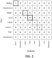
- the detected elements must be classified to know what type (also called class) they belong to, among all those that are supported; for example, those that have been mentioned above: buttons, check boxes etc.
- this classification stage may not be necessary if there is only one possible type of elements to be detected, such as in the case of database implementation, as will be later explained.
- Each class has its own characteristics and, for example, its own HTML (Hypertext Markup Language) code, so it is important to distinguish them as accurately as possible.
- HTML Hypertext Markup Language
- a machine learning model is used, trained with its own data set, which follows the syntax that has been defined on a prior step.
- the machine learning model used can be of the type of deep Convolutional Neural Network (CNN).
- This syntax can be defined in any way, as long as the correspondence between drawings and the various elements is clear. Preferably it should be simple and should be known by the user to know how to draw each element, that is, the type of drawing that corresponds to each element. Thus, for example, a button can be drawn as a rectangle or square with a text (or even a mere random layout) inside, or an image can be indicated as a crossed-out rectangle or square (with an X inside). This is just an example and any other syntax for drawing the various elements can be used.
- the model to classify the elements detected in the images preferably requires a reduced training time and acquires high accuracy with few epochs.
- a technique such as the Transfer Learning can be used in an embodiment.
- This Machine Learning technique consists of using a model that has already been trained and adjusted with a much larger set of images, in a more complex classification problem, and adapt it to the specific problem (in this case the detection of elements), training for that purpose only the last layers of the neural network. This is just one example and other types of machine learning techniques can be used in other embodiments.
- the overall accuracy of the model in the validation set is 92.75% and requires 2.5 MB.
- the overall accuracy of the model in the validation set is 92.75% and requires 2.5 MB.
- the confusion matrix for this particular example is shown in Figure 2 .
- OCR optical character recognition
- Optical Character Recognition is carried out on elements that may potentially contain some text.
- these elements can be, among others: buttons, labels, drop-down, "checkboxes” and "radio buttons”.
- the objective of this process is to customize the elements with the data (text) that the user has included in his drawing, thus achieving a more accurate result (closer to the expected).
- Recognition consists of two parts: On the one hand, the identification of the text sets within the element and, on the other hand, the transcription of the text they contain.
- the first part is used for elements that require a specific layout, for example, check boxes and radio buttons (radio buttons) in the case of web applications. Due to this process, it will be possible to know, for example, the number of alternatives that each of them contemplates, as well as their order.
- the second part of the recognition is fundamental for all of them, since it allows obtaining the texts that will be included in the elements generated in a subsequent stage.
- This procedure is also basic to be able to recognize the flow of the future computer project generated, since it will allow for example to extract from the top label of the drawings the name of the view and the buttons as well as links created between elements or pages or other functions or interactions between elements.
- a default character or group of characters
- This default character or group of characters
- the last step will be to place all the elements in their respective place in the generated code (HTML code in the example), as well as create the necessary paths and interactions in the implemented project.
- Project Execution Flow Generation (6) can be any type of computer project; in the case of the example, this project (software) would be a web application.
- Most computer projects (and especially web pages) consist of multiple views and generally have a flow (called an execution flow, an operational flow, or an interaction flow between elements), integrated with buttons or with different elements that allow to divide and organize the information there contained in a better way. Therefore, the development of a tool for the generation of web projects quickly and easily must contemplate this scenario. That is why the proposed solution gives the user the possibility of generating the aforementioned execution flow using the drawings themselves (drafts).
- the solution proposes a predefined syntax (in the form of policies or rules) that the user must follow to allow the electronic device that implements this invention to detect the endpoints between the views, as well as the names of each of them or, more generally speaking, where the link points or interactions between the different components of the project can be found.
- the views to be integrated into a flow must be labeled with a name or title (integrated into an element of type 'label'), for example, at the top of the drawing.
- elements for example, buttons
- text appears a default character or group of characters for example, the character ⁇ #
- the solution Upon understanding the flow required by the user, the solution will use an appropriate tool (in the case of the example you can use the Flask application for web application development or any other known tool that does this function) to create appropriate dynamic routes. For each view or linked element, a new path with the same name will be generated, with the aim of returning its code (in the example HTML code). The elements (e.g. buttons) will be linked using these paths, thus creating a fully functional application. All this allows to fulfill the suggested objective of generating an application with flow between views (or more generally speaking, flow of interaction between elements) using only the drawings of the user.
- an appropriate tool in the case of the example you can use the Flask application for web application development or any other known tool that does this function
- For each view or linked element a new path with the same name will be generated, with the aim of returning its code (in the example HTML code).
- the elements e.g. buttons
- All this allows to fulfill the suggested objective of generating an application with flow between views (or more generally speaking, flow of interaction between elements
- Final deployment (resulting code): Once the elements that make up the design drawn by the user have been obtained and identified, and the text there contained, the structure of the desired computer project is generated (7) (in the case of the example, the backend part will generate the structure of the new web application). To this end you can use any suitable known tool (in the case of the example you can use the Flask application or any other known tool that does this function). This will generate the corresponding code files (in the case of a web application, these files can have the extension .html and can be saved in the templates folder of the new generated application). That is, the files whose execution allows the implementation of the computer project are generated or, in other words, these files contain the necessary code for the implementation of the computer project.
- the files with the resulting code (9) can be downloaded (10) by the user.
- this download will involve the download of HTML files (11) and in the case of using the Flask tool it will also involve the download of the Flask application created (12).
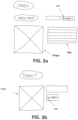
- Figures 3a and 3b show a non-limiting example of input drawings to this tool for a specific case.
- Figure 3a shows the index page that includes a title, an image, a possible text, and a link (indicated by the # character) to the submission page (better known as "Submit").
- the submission page is shown in Figure 3b with an image, buttons and a link to the index page.
- This tool can be implemented in the form of a web application that allows the user to translate a drawing on a web page (such application in an example can be called "Draw your Web").
- the tool can have a main front where the function of uploading files is located; this will allow the user to select and send the photographs of the drawings made previously to the backend part.
- the procedure executed by the tool to understand the input image (or images) is initiated by using techniques of Computer Vision, with the aim of extracting all the elements that compose it.
- the next step will be to know the class (type) of each of them.
- the tool has its own training set, which includes hand drawings of all components, with which a deep Convolutional Network has been trained that allows the classification work.
- the last step is to use OCR techniques to understand the texts so that you can apply them to the final result.
- the generation of the results will begin (the web application and the generated files, for example, in the form of a .zip file with the generated HTML codes) and the deployment of the resulting application.
- This second use case is a tool that provides the user with the ability to generate a database and its script (following the syntax of My SQL or any other) from one or more drawings. To do this, the user will draw one or more tables (and their relationships) according to a default syntax (preferably attached in the tool documentation). Each of the tables will be composed of common elements within the design of a database, such as data, its type, key type, and references. Once the drawing has been made, we will proceed to their photograph/scan and then proceed to the upload of the file with that photograph(s) to begin the analysis.
- This tool can be implemented in the form of a web application that allows the user to translate a drawing in a database (such application in an example can be called "Draw your database” or “Draw your DB”).
- the tool can have a main frontend where the function of uploading files is located; this will allow the user to select and send the photographs of the drawing or drawings made.
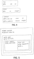
- Figure 4 shows a non-limiting example of an input drawing to this tool for a specific case.
- the database fields in this example will be AULA (classroom in English), ALUMNO (Student in English), and CURSOAULA.
- This third use case is a tool that provides the user with the ability to generate Cloud architectures, from one or more drawings.
- This tool can be implemented in the form of a web application that allows the user to translate a drawing in an architecture or network infrastructure in the cloud (such application in an example can be called "Draw your Cloud").
- the application can have a main frontend where the function of uploading files is located; this will allow the user to select and send the images (photographs or scan) of the drawing or drawings made for the generation of the infrastructure in the cloud.
- this generation will not be direct, and it will be necessary to use a software tool that allows the creation of more or less complex software infrastructures of this type.
- "Terraform” will be used, which is a tool that defines a high-level language that allows to create infrastructure as code and use it to deploy architectures in most of the Cloud providers in the market. Therefore, the result of this use case will be the generation of Terraform code ( . tf) from a drawing so that, later, the user can collect this exit code and use it in the aforementioned Terraform tool for creating infrastructure in the cloud (the use of Terraform is only an example and any other software tool with appropriate functionality can be used.)
- Cloud architectures are composed of different components structured in the form of a tree, with a series of configurable parameters for each of them.
- the user will draw the configuration of the Cloud architecture following a simple syntax previously defined (preferably attached in the documentation of the tool). This syntax seeks to establish a midpoint between flexibility in design and the simple and rapid generation of architecture; for each element, the user can be allowed to enter certain settings preceded by a certain character or groups of characters (in one embodiment that character is '#'), all explained in the project documentation.
- Figure 5 shows a non-limiting example of an input drawing to this tool for a specific case.
- the level of abstraction achieved by the tool which is founded (but is much higher) on which already offers the software infrastructure creation tool, in this example Terraform.
- This fourth use case is a tool that provides the user with the ability to generate neural networks (for example, deep neural networks) from one or more drawings.
- This tool can be implemented in the form of a web application that allows the user to translate a drawing in a neural network (such application in an example can be called "Draw your neural network").
- the application can have a main frontend where the function of uploading files is located; this will allow the user to select and send the images of the drawing or drawings made for the generation of the neural network.
- “Keras” will be used (deep learning development library written in Python, which allows to define models in a very simple way and, above all, the possibility of exporting and/or importing models from a json format). This last functionality will make it possible that the tool can generate from the drawing a model in Python and with it, using the native export of the library, transform it to json format.
- the output of the tool will be double: on the one hand, the model (written in Python using Keras) and, on the other hand, a file (in JSON format) in which the model is fully defined and can be exported to other tools (the use of Keras is only an example and any other software tool with appropriate functionality can be used).
- a visual syntax is pre-defined to make drawings even more intuitive.
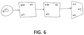
- input layers are illustrated as circles; intermediate layers as squares; and output layers as trapezes.
- the connection of these elements by means of arrows allows to define a complete and visually clear neural network (this is only an example, and any other definition can be used for the syntax).
- Figure 6 shows a non-limiting example of an input drawing to this tool for a specific case. You can see four different layers (one input, two intermediate and one output) with their corresponding configurations that follow the syntax of the project.
- the proposed tool will generate the codes shown below, which correspond to 1) the definition in JSON format of the model's dense layer" and 2) definition of the model obtained in python language:
- the proposed invention allows the implementation of an architecture of a software project from a simple draft (hand-made) of its design. This applies to many different architectures and, in general, if it is possible to design this architecture on paper, it is potentially possible to convert it into a implementation by applying this solution.
- some appropriate software tool can be used in each case.
- the Flask application can be used for the generation of the code files; if the project is a database for the generation of the files, the MySQL tool can be used; if the project is a cloud architecture you can use the Terraform tool to generate the cloud architecture (from the generated files).
- the Keras tool can be used.
- this implementation is able to generate everything necessary to implement a computer project. This greatly facilitates the implementation both to generate a proof of concept and even to generate a solid foundation for its creation. Moreover, it allows users without advanced knowledge to be able to generate this type of projects in a simple, fast and visual way.
Landscapes
- Engineering & Computer Science (AREA)
- Theoretical Computer Science (AREA)
- Physics & Mathematics (AREA)
- Computer Vision & Pattern Recognition (AREA)
- General Physics & Mathematics (AREA)
- Software Systems (AREA)
- Multimedia (AREA)
- Artificial Intelligence (AREA)
- Evolutionary Computation (AREA)
- General Engineering & Computer Science (AREA)
- Health & Medical Sciences (AREA)
- Computing Systems (AREA)
- Databases & Information Systems (AREA)
- General Health & Medical Sciences (AREA)
- Medical Informatics (AREA)
- Computer Hardware Design (AREA)
- Geometry (AREA)
- Machine Translation (AREA)
Applications Claiming Priority (1)
| Application Number | Priority Date | Filing Date | Title |
|---|---|---|---|
| PCT/ES2021/070083 WO2022167704A1 (es) | 2021-02-04 | 2021-02-04 | Implementación de proyecto informático a partir de boceto de diseño |
Publications (2)
| Publication Number | Publication Date |
|---|---|
| EP4290366A1 true EP4290366A1 (de) | 2023-12-13 |
| EP4290366A4 EP4290366A4 (de) | 2024-10-16 |
Family
ID=82740929
Family Applications (1)
| Application Number | Title | Priority Date | Filing Date |
|---|---|---|---|
| EP21924501.6A Pending EP4290366A4 (de) | 2021-02-04 | 2021-02-04 | Implementierung eines computerprojekts auf der basis einer designkontur |
Country Status (3)
| Country | Link |
|---|---|
| US (1) | US20240087351A1 (de) |
| EP (1) | EP4290366A4 (de) |
| WO (1) | WO2022167704A1 (de) |
Family Cites Families (7)
| Publication number | Priority date | Publication date | Assignee | Title |
|---|---|---|---|---|
| US20120213429A1 (en) * | 2011-02-17 | 2012-08-23 | Infosys Technologies Limited | System and method for extracting flowchart information from digital images |
| US10048946B2 (en) * | 2016-03-24 | 2018-08-14 | Microsoft Technology Licensing, Llc | Converting visual diagrams into code |
| US10489126B2 (en) * | 2018-02-12 | 2019-11-26 | Oracle International Corporation | Automated code generation |
| KR102089801B1 (ko) * | 2018-04-19 | 2020-03-16 | 한남대학교 산학협력단 | 심볼마커를 사용한 스케치이미지 기반 사용자 인터페이스 자동생성 시스템 |
| US10817266B2 (en) * | 2018-09-25 | 2020-10-27 | Salesforce.Com, Inc. | Converting a captured image to visual programming logic for an automation building tool |
| US11080025B2 (en) * | 2019-07-08 | 2021-08-03 | International Business Machines Corporation | Back-end application code stub generation from a front-end application wireframe |
| CN112114803B (zh) * | 2020-08-25 | 2024-05-24 | 山东浪潮科学研究院有限公司 | 基于深度学习的ui界面的前端代码生成方法、设备及介质 |
-
2021
- 2021-02-04 EP EP21924501.6A patent/EP4290366A4/de active Pending
- 2021-02-04 US US18/264,201 patent/US20240087351A1/en active Pending
- 2021-02-04 WO PCT/ES2021/070083 patent/WO2022167704A1/es not_active Ceased
Also Published As
| Publication number | Publication date |
|---|---|
| EP4290366A4 (de) | 2024-10-16 |
| US20240087351A1 (en) | 2024-03-14 |
| WO2022167704A1 (es) | 2022-08-11 |
Similar Documents
| Publication | Publication Date | Title |
|---|---|---|
| CN111026842B (zh) | 自然语言处理方法、自然语言处理装置及智能问答系统 | |
| CN112749284B (zh) | 知识图谱构建方法、装置、设备及存储介质 | |
| EP3433732B1 (de) | Umwandlung visueller diagramme in code | |
| KR100936204B1 (ko) | 카피 앤드 페이스트 처리 방법, 장치 및 기록 매체 | |
| Nikbakht et al. | Tspec-llm: An open-source dataset for llm understanding of 3gpp specifications | |
| JP2021504781A (ja) | ブロックに基づく文書メタデータの抽出のための方法、コンピュータ・プログラム及びシステム | |
| CN105095067A (zh) | 用户界面元素对象识别及自动化测试的方法和装置 | |
| CN112631586B (zh) | 一种应用开发方法、装置、电子设备和存储介质 | |
| CN102663138A (zh) | 一种公式查询条件的输入方法与装置 | |
| US20250245256A1 (en) | Information processing system and method for processing information | |
| KR102366182B1 (ko) | 인공지능을 활용한 슬라이드 자동생성 방법 및 서버 | |
| Llerena-Izquierdo et al. | Mobile application with cloud-based computer vision capability for university students’ library services | |
| EP3779672B1 (de) | System und verfahren zur erzeugung einheitlicher erfahrungen auf digitalen plattformen | |
| CN116610304B (zh) | 页面代码生成方法、装置、设备和存储介质 | |
| US20250315422A1 (en) | Synthesizing Transformations to Data Files | |
| EP4290366A1 (de) | Implementierung eines computerprojekts auf der basis einer designkontur | |
| CN113761863B (zh) | 一种列表页面的配置方法、设备及存储介质 | |
| CN119226380A (zh) | 基于大语言模型快速筛选的数据库代码提取方法及系统 | |
| CN112732423A (zh) | 流程迁移方法、装置、设备及介质 | |
| KR20250058056A (ko) | 디스플레이가능한 콘텐츠의 엘리먼트에 대한 속성 결정 및 접근성 트리에 추가 | |
| JP2020135523A (ja) | 情報処理装置、情報処理方法及びプログラム | |
| CN111046243A (zh) | 一种基于网络拓扑图配置sonic的方法、设备及介质 | |
| Kocic et al. | An approach for document image analysis using Faster RCNN deep convolutional network | |
| US20250371262A1 (en) | Multilingual support using llm for document information extraction | |
| CN119884528B (zh) | 基于大模型数据增强的web元素web解析方法 |
Legal Events
| Date | Code | Title | Description |
|---|---|---|---|
| STAA | Information on the status of an ep patent application or granted ep patent |
Free format text: STATUS: THE INTERNATIONAL PUBLICATION HAS BEEN MADE |
|
| PUAI | Public reference made under article 153(3) epc to a published international application that has entered the european phase |
Free format text: ORIGINAL CODE: 0009012 |
|
| STAA | Information on the status of an ep patent application or granted ep patent |
Free format text: STATUS: REQUEST FOR EXAMINATION WAS MADE |
|
| 17P | Request for examination filed |
Effective date: 20230724 |
|
| AK | Designated contracting states |
Kind code of ref document: A1 Designated state(s): AL AT BE BG CH CY CZ DE DK EE ES FI FR GB GR HR HU IE IS IT LI LT LU LV MC MK MT NL NO PL PT RO RS SE SI SK SM TR |
|
| DAV | Request for validation of the european patent (deleted) | ||
| DAX | Request for extension of the european patent (deleted) | ||
| RAP1 | Party data changed (applicant data changed or rights of an application transferred) |
Owner name: TELEFONICA INNOVACION DIGITAL, S.L.U. |
|
| RAP3 | Party data changed (applicant data changed or rights of an application transferred) |
Owner name: TELEFONICA INNOVACION DIGITAL, S.L.U. |
|
| A4 | Supplementary search report drawn up and despatched |
Effective date: 20240916 |
|
| RIC1 | Information provided on ipc code assigned before grant |
Ipc: G06F 8/20 20180101ALI20240910BHEP Ipc: G06V 30/422 20220101ALI20240910BHEP Ipc: G06V 30/10 20220101ALI20240910BHEP Ipc: G06V 10/82 20220101ALI20240910BHEP Ipc: G06V 10/774 20220101ALI20240910BHEP Ipc: G06F 8/34 20180101AFI20240910BHEP |