EP3433732B1 - Umwandlung visueller diagramme in code - Google Patents
Umwandlung visueller diagramme in code Download PDFInfo
- Publication number
- EP3433732B1 EP3433732B1 EP17714990.3A EP17714990A EP3433732B1 EP 3433732 B1 EP3433732 B1 EP 3433732B1 EP 17714990 A EP17714990 A EP 17714990A EP 3433732 B1 EP3433732 B1 EP 3433732B1
- Authority
- EP
- European Patent Office
- Prior art keywords
- code
- component
- components
- diagram
- code templates
- Prior art date
- Legal status (The legal status is an assumption and is not a legal conclusion. Google has not performed a legal analysis and makes no representation as to the accuracy of the status listed.)
- Active
Links
Images

Classifications
-
- G—PHYSICS
- G06—COMPUTING OR CALCULATING; COUNTING
- G06F—ELECTRIC DIGITAL DATA PROCESSING
- G06F8/00—Arrangements for software engineering
- G06F8/30—Creation or generation of source code
- G06F8/34—Graphical or visual programming
-
- G—PHYSICS
- G06—COMPUTING OR CALCULATING; COUNTING
- G06F—ELECTRIC DIGITAL DATA PROCESSING
- G06F8/00—Arrangements for software engineering
- G06F8/30—Creation or generation of source code
- G06F8/35—Creation or generation of source code model driven
-
- G—PHYSICS
- G06—COMPUTING OR CALCULATING; COUNTING
- G06V—IMAGE OR VIDEO RECOGNITION OR UNDERSTANDING
- G06V30/00—Character recognition; Recognising digital ink; Document-oriented image-based pattern recognition
- G06V30/40—Document-oriented image-based pattern recognition
- G06V30/42—Document-oriented image-based pattern recognition based on the type of document
- G06V30/422—Technical drawings; Geographical maps
-
- G—PHYSICS
- G06—COMPUTING OR CALCULATING; COUNTING
- G06V—IMAGE OR VIDEO RECOGNITION OR UNDERSTANDING
- G06V30/00—Character recognition; Recognising digital ink; Document-oriented image-based pattern recognition
- G06V30/10—Character recognition
Definitions
- a computer program development team e.g., one or more design architects, developers, programmers, coders, etc.
- a diagram of the computer program is first created.
- members of the development team often gather in a collaborative environment such as conducting a meeting in a conference room to illustrate (e.g., draw) the diagram, for example, on a dry-erase white board. From that point, the process of converting the diagram on the white board into code structures is a manual process that typically requires sub-optimal utilization of time.
- the diagram drawn on the white board may need to be converted (e.g., copied) into a digital format and then be passed to developer(s) (e.g., coders, programmers).
- developer(s) e.g., coders, programmers
- the developer(s) then spend a considerable amount of time reviewing the design architecture of the diagram to identify aspects of the diagram (e.g., the components, the structure of the components, the interactions of the components, and/or the behavior of the components).
- the developer(s) can begin to create the code structures for the computer program (e.g., write the code from scratch).
- a developer is unaware and/or unfamiliar with programming features made available via a particular programming platform. For example, a developer may be unable to leverage the latest and most applicable design patterns and best practices associated with particular functionality.
- US 6742175 B1 relates to a component-based source code generator that uses a set of generation instructions and a set of parameters to generate nearly-repetitive and repetitive source code.
- the developer specifies to the code generator what to generate through the use of generation instructions.
- the developer specifies the target components and the code that should be generated.
- the generation process uses information contained in the modeling tool. Consequently, the generated code never has to be modified directly by the developer, greatly reducing maintenance time, minimizing errors, and improving code consistency.
- Yong Chao Song ET AL "The Design and Implementation of Code Generation Based on J2EE in the Development of JBPM Workflow System", Applied Mechanics and Materials, vol. 263-266, 27 December 2012, pages 1961-1968 relates to the design and implementation of code generation based on J2EE in the development of JBPM workflow system.
- a code generation tool generates code by parsing a static form source code and loading a code generation template.
- the code generation tool greatly shortens the JBPM workflow system development cycle and reduces the cost of software development, which has a good practicability and scalability.
- US 2016/034441 A1 relates to systems, apparatuses and methods for generating a graphical user interface (GUI) conforming to a graphical representation employ computer vision, optical character recognition, and other techniques to generate a structure of the GUI as a view hierarchy.
- GUI graphical user interface
- a development project with source code and resource files is created to generate an application having the GUI.
- the application and GUI are applicable to mobile and other platforms using various operating systems, such as Android, iOS, and others.
- US 2009/064092 A1 describes optimizing a dataflow diagram before code generation is carried out. Once such optimization is finalized, source code is generated from the visual programming dataflow diagram. Hereby, for each type of work unit, a source code template is applied.
- US 5 386 508 A relates to a program generator including: a character/figure separating device for separating characters and line graphics from an input flowchart image.
- a character recognizing device performs character recognition on the separated character portion and a figure recognizing device extracts symbols from the line graphics.
- a program code generating device generates instructions corresponding to the symbols and generates a program code by combining the generated instructions with the results of the character recognition that corresponds to the positions in which the symbols have been extracted.
- a desired computer program can be prepared by simple steps in a rapid and accurate way.
- US 2014/214396 A1 relates to a method, system and computer program product for creation of specification properties for a visual model of a system.
- US 9 223 547 B1 relates to generating text in a structured language, such as source code in a programming language, based on audio input.
- Audible tokens may be associated with higher-level constructs, including design elements such as methods, classes, design patterns, and so forth. Additionally, audible tokens may be associated with lower-level syntactic constructs of a programming language, such as programming language keywords, tokens, and so forth.
- Techniques may receive and parse the audio input including the audible tokens, and generate source code output. Techniques may also provide audio information indicating a development context that may otherwise be indicated visually in a development environment.
- the techniques and systems described herein convert a visual illustration of a diagrammed computer program into equivalent, structured code solutions.
- the conversion can be implemented in association with any programming language such that the components in the diagram can subsequently be mapped to their equivalent, structured source code.
- the mapping is based on computer recognition of the components illustrated in the diagram.
- the mapping can also be based on computer recognition of the structure of the components illustrated in the diagram, the interactions of the components illustrated in the diagram, and/or the behavior of the components illustrated in the diagram.
- the techniques and systems implement a tool that receives a diagram of a computer program.
- the diagram can comprise an image (e.g., a photo of the diagram drawn on a white board that is captured by a camera) or the diagram can comprise content originally generated in electronic form (e.g., use of a computer-implemented digital drawing program to generate the diagram in a digital format).
- the diagram represents a design architecture of a computer program, and therefore, the diagram may illustrate individual components, as well as a structure for the individual components and interactions between the individual components.
- the tool is configured to recognize (e.g., optically) characteristics of the components illustrated in the diagram. In some implementations, the tool uses the characteristics to determine a programming language associated with the design architecture.
- the tool further uses the characteristics to associate the component with one or more code templates.
- a code template is pre-populated with source code of the programming language.
- the tool enables the code templates to be output (e.g., displayed) on a device associated with a user so that the user can provide input that updates and finalizes the source code.
- the recognized characteristics used to identify the components and/or map the components to code templates can comprise keywords, visual relationships (e.g., representing interactions), and/or visual shapes.
- a keyword can label and/or name a component so that the keyword can be used by the tool to map the component to a code template.
- a visual relationship can visually connect two or more components (e.g., components with an arrow drawn between, components illustrated adjacent to one another such that they are touching each other, a component visually illustrated on top of another component, a visual position of a component in a sequence of components in the diagram, spacing or a distance between two components, etc.) so that the visual connection can be used by the tool to map a component to a code template.
- a visual shape e.g., a square, a circle, a diamond, an oval, a unique shape pre-defined for a component, etc.
- a visual shape can be used to distinguish a first component of a first type or classification from a second component of a second type or classification such that the visual shape can be used by the tool to map the component to a code template.
- the tool also uses the characteristics to identify various coding options, configure a code template to present the various coding options, enable the coding options to be selected by the user, and/or recommend a coding option.
- the coding options reflect the latest and most commonly used (e.g., the most popular): design patterns for particular functionality implemented in association with a particular programming language and/or best practices for particular functionality implemented in association with a particular programming language. Consequently, via the use of code templates associated with the recognized characteristics, structured code solutions can be generated efficiently. That is, a developer is not required to generate or write the code from scratch but rather review code templates with pre-populated code, update the pre-populated code, and/or make selections of coding options so that the code solutions can be finalized.
- the techniques and systems described herein provide a tool for use in association with the development of a computer program.
- a computer program development team e.g., one or more design architects, developers, programmers, coders, etc.
- the tool can use the tool to efficiently generate code solutions using an illustrated diagram (e.g., drawn on a dry-erase white board, drawn using a digital drawing program such as Microsoft ® Visio ® , etc.).
- the tool receives a diagram illustrating the design architecture (e.g., an uploaded image that visually captures a diagram).
- the tool can then perform recognition techniques to identify characteristics of the components illustrated in the diagram.
- characteristics of an individual component can include keywords written on the component, a visual shape of the component, and visual relationship(s) between the component and other components illustrated in the design architecture.
- the tool can determine a programming language (e.g., in a human-readable format) with which the diagram is associated and/or maps the components illustrated in the diagram to previously generated code template(s).
- an individual code template can be pre-populated with source code written in the determined programming language.
- the source code pre-populated in a code template can be "base" code such that it provides a good starting point for a developer to understand the functionality being coded, yet also enables the developer to make changes that are tailored to a particular computer program and/or the desires of the development team of the particular computer program. Consequently, a code template is interactive and is output (e.g., displayed) so that a developer can provide input to update the source code (e.g., modify pre-populated code, add new code, delete pre-populated code, etc.). Furthermore, a sequence of code templates can provide an initial structure for one or more code solutions required to implement the computer program being developed.
- a "component" of a diagram can represent a separate or a modular part of a computer program (e.g., an application) that contains semantically related functionality, data, hardware, or a combination thereof.
- a component can be illustrated in a diagram to emphasize a separation of concerns for a development team (e.g., separate tasks required to be implemented so the computer program executes correctly).
- a component can be associated with particular functionality of a programming platform (e.g., an integrated development environment (IDE) such as Microsoft ® Visual Studio ® ).
- IDE integrated development environment
- a component can represent software, aspects of hardware, or a combination of both software and hardware.
- a component can represent: a software package, a service (e.g., a web service, a networking service, a storage service, a cloud service, etc.), a resource (e.g., a web resource, a networking resource, a storage resource, a cloud resource, etc.), a device, a server, an interface (e.g., an application programming interface (API)), a debugger, an editor, and so forth. Consequently, components are used to separate a wide-range of functionality that is made available to developers via a programming platform.
- the components illustrated in the diagram are labeled with a name that comprises one or more keywords to distinguish one component from another (e.g., a standard or a commonly-used name for a component).
- an illustration of a diagram can directly (e.g., with little or no user involvement) be converted into code templates and developers do not have to concern themselves with reviewing and analyzing the design architecture to generate a robust code foundation as a starting point. Rather, by mapping the illustrated components of the diagram to code templates that are pre-populated with base code, developers are automatically provided with an initial structure from which coding can begin. Therefore, via the use of code templates, programming can be more consistent across various groups of developers and/or programming can also be of higher quality because variations in coding styles and in coding disciplines are reduced, if not made irrelevant. Even further, valuable time in the program development process is saved via the elimination of tasks, such as identifying and analyzing components of the diagram and/or generating the base code and/or initial structure required to implement code solutions for a computer program.
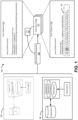
- FIG. 1 is a block diagram 100 that illustrates a conversion of a diagram illustrating a design architecture of a computer program or a portion of a computer program (e.g., such as an "app"), into code solutions.
- a diagram is created (e.g., drawn) on a surface (e.g., a physical surface and/or a digital surface).
- the surface can comprise a white board, a chalk board, a display screen, a touch screen, a projector screen, and so forth.
- the diagram can be hand-drawn 102 by a user (e.g., a developer using a white board in a conference room, a developer using a digital pen on a touch screen surface, etc.).
- the diagram can be generated, by a user, using computer drawing tools 104 (e.g., generated by a user within a computer diagramming program such as Microsoft ® Visio ® ).
- a diagram can include multiple different components, where an individual component comprises a separate or modular part of a computer program that contains semantically related functionality, data, hardware, or a combination thereof.
- both the hand-drawn diagram 102 and the computer-generated diagram 104 comprise a first component (e.g., "component 1"), a second component (e.g., "component 2"), a third component (e.g., "component 3"), a fourth component (e.g., "component 4"), and a fifth component (e.g., "component 5").
- a diagram can comprise a Unified Modeling Language (UML) diagram such as a Class diagram, a Sequence diagram, an Entity-Relationship (ER) diagram, a Use Case diagram, or a combination thereof. While FIG. 1 illustrates five components in the diagram, it is understood in the context of this document that a diagram can include any number of components (e.g., one, three, eight, ten, fifteen, fifty, one hundred, and so forth).
- UML Unified Modeling Language
- ER Entity-Relationship
- a tool 106 performs recognition techniques 108 on the diagram to identify the individual components therein and characteristics of the components. For example, an image of the diagram can be captured (e.g., by a camera) and uploaded to the tool 106 so the recognition can be performed. In another example, a diagram created in a digital format can be directly uploaded to the tool so recognition can be performed (e.g., hand-drawn on a touch screen using a digital pen, generated by a user in a computer diagramming program, etc.).
- the tool 106 is configured to use optical recognition techniques (e.g., optical character recognition (OCR)), shape recognition/classification techniques (e.g., number of sides, lengths of sides, angle detection, etc.) and/or other recognition techniques to identify characteristics of the diagram.
- OCR optical character recognition
- shape recognition/classification techniques e.g., number of sides, lengths of sides, angle detection, etc.
- the characteristics can comprise keywords, visual shapes, and/or visual relationships.
- the tool 106 can determine an intended programming language in which the design architecture of the diagram is to be implemented. Consequently, the tool 106 is configured to use the characteristics to create a semantic context corresponding to the various components in the diagram. Moreover, the tool 106 is configured to identify code templates pre-populated with source code useable to define code solution(s) 110 for the computer program.
- a code template is generated and/or provided by the tool 106 as a means for a developer to efficiently and effectively: review the pre-populated code associated with an illustrated component of the diagram, provide changes to the pre-populated code associated with an illustrated component of the diagram, add to the pre-populated code associated with an illustrated component of the diagram, and/or make selections of embedded coding options configured to further import code into the code template. Therefore, a code template provides code in an intermediate form such that the code can be efficiently reviewed and revised by a developer before it is finalized, yet the developer is no longer required to create all the code from scratch.
- a keyword can label and/or name a component so that the keyword can be used by the tool 106 to map the component to a code template.
- keyword(s) can include acronyms. Accordingly, each of "component 1", “component 2", “component 3", “component 4", and “component 5" illustrated in diagrams 102, 104 can comprise one or more keywords descriptive of the component. Keywords can be generally applicable to a variety of programming languages or keywords can be specifically associated with a particular programming language.
- keywords can include: “network”, “server”, “OEM” (Original Equipment Manufacturer), “package”, “database”, “connectivity”, “web”, “browser”, “debugger”, “editor”, “account”, “email”, “payment”, “send”, “receive”, “forms”, “files”, “.NET”, “Azure”, “Blob”, “MVC” (Model-View-Controller), “SQL” (Structured Query Language), and so forth.
- the keywords can be used to associate (e.g., map) an individual component, or multiple components, with code template 112 or code template 114, which are displayed on a user device of a developer for review.
- a visual relationship can visually connect two or more components so that the visual connection can be used by the tool 106 to map the component, or multiple components, to code template 112 or code template 114.
- a visual relationship can be recognized based on the diagrams 102, 104 showing that "component 1" interacts with "component 2" (e.g., via the arrow indicating that data is exchanged in a two-way manner) and that "component 5" sends information to "component 4" (e.g., via the arrow indicating that data is only sent one way).
- a visual relationship can be recognized based on the diagrams 102, 104 illustrating "component 3" and “component 4" next to each other, or based on the spacing or distance between component 3" and “component 4".
- a visual relationship can be recognized based on the diagrams 102, 104 illustrating "component 3” and “component 4" being placed over or on top of “component 2".
- a visual relationship can be described using keywords (e.g., "connect”, “send”, “receive”, “retrieve”, etc.).
- a visual shape can be used to distinguish a first component of a first type or classification from a second component of a second type or classification such that the visual shape can be used by the tool 106 to map the component to code template 112 or code template 114.
- the shapes can comprise squares, rectangles, ovals, or another common geometric shape.
- a visual shape can be pre-defined by the tool 106 for a specific component such as a database or a datastore (e.g., "component 1" in diagrams 102, 104).
- the characteristics of the diagram can be recognized and subsequently used by the tool 106 to map components to corresponding code templates 112, 114 as a starting point to generate and finalize (e.g., based on user review and input) code solutions 110 useable to implement the computer program or a portion of the computer program.
- the tool 106 also uses the recognized characteristics to identify various coding options 116 and present the various coding options 116 for selection within a code template 114 on a user device.
- the coding options 116 reflect the latest and most commonly used design patterns and/or best practices.
- a design pattern can be created and made available by a particular programming platform and can comprise a reusable solution to a commonly occurring problem within a given programming context.
- a best practice can also be created and made available by a particular programming platform and can comprise rules that the development community has learned over time which can help improve the quality of computer programs.
- the coding options 116 in FIG. 1 are associated with different code available to handle transient connectivity issues for "BlobClient".
- a first option may be associated with a transient fault handling block (e.g., an option implemented in association with Microsoft ® Azure ® services) and a second option may be associated with a circuit breaker handling block (e.g., also an option implemented in association with Microsoft ® Azure ® services). Therefore, the coding options 116 can provide different solutions to address a same or similar issue, where each solution has advantages and disadvantages to consider depending on the design architecture of the computer program (e.g., as illustrated in the diagram).
- a description of the features associated with a coding option may also be displayed to help the developer make a decision on which option to select.
- the tool 106 is configured to recommend a coding option (e.g., order the coding options displayed so that the first ordered coding option is a recommended option and the subsequent ordered coding options displayed are alternative options, provide a visual distinction that identifies a recommended coding option, etc.).
- a coding option e.g., order the coding options displayed so that the first ordered coding option is a recommended option and the subsequent ordered coding options displayed are alternative options, provide a visual distinction that identifies a recommended coding option, etc.
- the tool 106 Upon selection of an option (e.g., a user click on "HERE"), the tool 106 further imports additional code associated with the selected option into the code template 114.
- structured code solutions 110 can be efficiently finalized and verified. That is, a developer is not required to generate or write the code from scratch but rather review code templates that are pre-populated with source code, update the pre-populated source code, and/or make a selection of coding options 116 so that the code solutions 110 can be finalized.
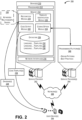
- FIG. 2 is a schematic diagram depicting an example environment 200 illustrating devices and/or modules configured to convert a diagram into the code solution(s). More particularly, the example environment 200 can include a service provider 202, service provider(s) 204, user device(s) 206, and network(s) 208.
- the service provider 202 is configured to implement the tool described herein (e.g., the tool 106 described above with respect to FIG. 1 ). Therefore, the service provider 202 can comprise one or more of an entity, server(s), platform, datacenter, cloud resource, etc., that facilitates program development assistance.
- the service provider 202 can be implemented in a non-distributed computing environment or can be implemented in a distributed computing environment.
- the service provider 202 can include device(s) 210 (e.g., servers), wherein an individual device can include processor(s) 212, memory 214, as well as network interface(s) 216 so that the device 210 can communicate with the user device(s) 206 and/or the service provider(s) 204 over network(s) 208.
- network(s) 208 can be wired and/or wireless, comprising a wide area network (WAN), a local area network (LAN), a personal area network (PAN), a network specific to a datacenter (e.g., an Intranet, a storage area network (SAN)), a mobile telephone network (MTN), etc.
- WAN wide area network
- LAN local area network
- PAN personal area network
- MTN mobile telephone network
- Communications between devices can utilize any sort of communication protocol known in the art for sending and receiving information and/or messages, such as the Transmission Control Protocol/Internet Protocol (TCP/IP) and/or the User Datagram Protocol (UDP).
- TCP/IP Transmission Control Protocol/Internet Protocol
- UDP User Datagram Protocol
- the processor(s) 212 can be a single processing unit or a number of units, each of which could include multiple different processing units.
- the processor(s) 212 can include a microprocessor, a microcomputer, a microcontroller, a digital signal processor, a central processing unit (CPU), a graphics processing unit (GPU), etc.
- CPU central processing unit
- GPU graphics processing unit
- some or all of the techniques described herein can be performed, at least in part, by one or more hardware logic components.
- illustrative types of hardware logic components include a Field-Programmable Gate Array (FPGA), an Application-Specific Integrated Circuit (ASIC), an Application-Specific Standard Products (ASSP), a state machine, a Complex Programmable Logic Device (CPLD), other logic circuitry, a system on chip (SoC), and/or any other devices that perform operations based on instructions.
- the processor(s) 212 can be configured to fetch and execute computer-readable instructions stored in the memory 214.
- the memory 214 can include one or a combination of computer-readable media.
- “computer-readable media” includes computer storage media and communication media.
- Computer storage media includes volatile and non-volatile, removable and non-removable media implemented in any method or technology for storage of information, such as computer-readable instructions, data structures, program modules, or other data.
- Computer storage media includes, but is not limited to, phase change memory (PCM), static random-access memory (SRAM), dynamic random-access memory (DRAM), other types of random access memory (RAM), read only memory (ROM), electrically erasable programmable ROM (EEPROM), flash memory or other memory technology, compact disk ROM (CD-ROM), digital versatile disks (DVD) or other optical storage, magnetic cassettes, magnetic tape, magnetic disk storage or other magnetic storage devices, or any other medium that can be used to store information for access by a computing device.
- PCM phase change memory
- SRAM static random-access memory
- DRAM dynamic random-access memory
- RAM random access memory
- ROM read only memory
- EEPROM electrically erasable programmable ROM
- flash memory or other memory technology
- compact disk ROM CD-ROM
- DVD
- communication media includes computer-readable instructions, data structures, program modules, or other data in a modulated data signal, such as a carrier wave.
- computer storage media does not include communication media.
- the memory 214 can also include an operating system configured to manage hardware and services within and coupled to the device 210 for the benefit of other device components and other devices.
- the memory 214 can include a recognition module 218, a template identification module 220, a code output module 222, a coding option module 224, and a datastore 226, each of which is further described herein.
- the term "module” is intended to represent example divisions of executable instructions for purposes of discussion, and is not intended to represent any type of requirement or required method, manner or organization. Accordingly, while various "modules" are described, their functionality and/or similar functionality could be arranged differently (e.g., combined into a fewer number of modules, broken into a larger number of modules, etc.).
- any or all of the modules can be implemented in whole or in part by hardware (e.g., a specialized processing unit, etc.) to execute the described functions.
- the recognition module 218 is configured to receive, via network(s) 208, a diagram 228 from a user device 206.
- the diagram 228 can comprise an image (e.g., captured by a camera) of a hand-drawn diagram that is uploaded from the user device 206 to the device 210.
- the diagram 228 can comprise content digitally formatted and uploaded from the user device 206 to the device 210 (e.g., content hand-drawn on a touch screen using a digital pen, content generated by a user in a computer diagramming program, etc.).
- the recognition module 218 is configured to implement recognition techniques on the diagram 228 to identify characteristics 230 of the components.
- the characteristics 230 can include one or more of: keywords, visual relationships, and/or visual shapes.
- a user device 206 can comprise a desktop computing device, a server device, a mobile device, a laptop computing device, a tablet device, a wearable device, a game console, a media player device, a camera, or any other sort of computing device.
- the template identification module 220 is configured to use the identified characteristics 230 of the diagram 228 to determine a programming language associated with the design architecture of the diagram 228.
- the template identification module 220 is also configured to use the characteristics to associate an individual component with one or more code templates pre-populated with source code.
- the datastore 226 stores a group of code templates 232 associated with a first programming language, a group of code templates 234 associated with a second programming language, a group of code templates 236 associated with a third programming language, and so forth.
- Each code template stored in the datastore 226 can be associated with one or more keywords, one or more visual relationships, one or more visual shapes, or a combination thereof.
- the template identification module 220 uses the characteristics 230 of the diagram 228 to map the illustrated components to a series of code templates 238 that provide code solutions for the design architecture of the diagram 228.
- the code templates identified may be structured (e.g., ordered, sequenced, etc.) based on the characteristics 230 as well.
- the code output module 222 is then configured to provide the identified code templates 238 to the user device 206 (e.g., cause the code templates 238 to be displayed) so that the user (e.g., a developer) can interact with the code templates 238 and efficiently and effectively: review the pre-populated code in the code templates 238, provide changes to the pre-populated code in the code templates 238, add to the pre-populated code in the code templates 238.
- the coding option module 224 is configured to identify a portion of code in a code template 238 that is associated with multiple different coding options. To determine the different coding options, the coding option module 224 can interact with various programming platforms 240 hosted by devices and/or resources of the service provider(s) 204. For example, the coding options can be associated with design patterns and/or best practices that may be applicable to a computer program based on the specific design architecture (e.g., based on the components and characteristics recognized in the diagram). In various implementations, service provider 202 and service provider 204 can be the same service provider.
- FIGS. 3 , 4 , and 6 individually illustrate an example process for employing the techniques described herein.
- the example processes are illustrated as logical flow graphs, each operation of which represents a sequence of operations that can be implemented in hardware, software, or a combination thereof.
- the operations represent computer-executable instructions stored on one or more computer-readable storage media that, when executed by one or more processors, configure a device or a system to perform the recited operations.
- computer-executable instructions include routines, programs, objects, components, data structures, and the like that perform particular functions.
- the order in which the operations are described is not intended to be construed as a limitation, and any number of the described operations can be combined in any order and/or in parallel to implement the process. Further, any of the individual operations can be omitted.
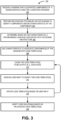
- FIG. 3 is a flow diagram of an example process 300 to convert a diagram into code solutions.
- the example process 300 can be implemented in association with various elements illustrated in FIGS. 1 and 2 .
- a diagram that illustrates components of a design architecture for at least a portion of a computer program is received.
- a program development team may draw a diagram on a white board, snap a picture of the diagram when it's completed, and upload the picture of the diagram to the tool 106 (e.g., the recognition module 218).
- recognition techniques are performed on the diagram to identify characteristics of the components.
- the characteristics can include keywords, visual shapes, visual relationships, or a combination thereof.
- a programming language associated with the design architecture of the diagram is determined.
- the template identification module 220 uses the characteristics to associate the diagram 228 with one of the programming languages for which code templates are stored in the datastore 226.
- the characteristics are used to associate the components of the diagram with code templates.
- the template identification module 220 can recognize keyword(s) that label or name (e.g., identify) a component and use the keyword(s) to map the component to a code template or multiple code templates.
- the recognition module 218 can recognize a visual shape of a component and use the visual shape to map the component to a code template or multiple code templates.
- the recognition module 218 can recognize a visual relationship of a component and use the visual relationship to map the component to a code template or multiple code templates.
- a visual relationship can comprise: a first component visually illustrated on top of (e.g., over) a second component in a diagram, a visual connection (e.g., an arrow or a line) between a first component and a second component in the diagram, a visual position of a first component in a sequence of components in the diagram (e.g., position of a component in a flow chart), a first visual position of a first component compared to a second visual position of a second component in the diagram (e.g., a measured distance or spacing between components), or a size of a first component compared to a size of a second component in the diagram.
- the code templates are output (e.g., displayed on a user device).
- the code output module 222 can output one or more first code templates associated with one or more first components illustrated in the diagram 228 (e.g., based on the recognized structure, interactions, and behavior).
- code output module 222 is configured to provide a visual distinction in association with areas of the code templates that need to be updated with specific code (e.g., a highlighted area).
- the code templates are updated based on the user input.
- the process upon receiving an instruction indicating that the user wants to view the next code template(s), the process returns to 310 and the code output module 222 can output, following the output of the first or previous code templates, one or more second or subsequent code templates associated with one or more second or subsequent components illustrated in the diagram 228 (e.g., based on the recognized structure, interactions, and behavior).
- the tool 106 is configured to provide the code templates for the design architecture in a structured and ordered format based on the characteristics of the components. A subset of the set of code templates output can be associated with a code solution.
- the tool 106 can analyze the syntax and semantics of the code solution and determine that the code solution will execute properly.
- the tool 106 uses an application programming interface (API) to interact with an external programming platform 240 to verify the code solution.
- API application programming interface
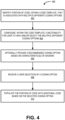
- FIG. 4 is a flow diagram of an example process 400 to provide recommended coding options for a portion of code in a code template and receive a user-selection of a selected coding option.
- the example process 400 can be implemented in association with various elements illustrated in FIGS. 1 and 2 , and also in association with operations 310, 312, and 314 in the example process 300 of FIG. 3 .
- a portion of code, within a code template, that is associated with multiple different coding options is identified.
- the coding option module 224 uses the characteristics 230 to determine that the computer program, based on the design architecture of the diagram 228, is to implement particular functionality and that the particular functionality can be coded in more than one way. This determination can be made based on knowledge of different options provided by programming platforms 240 (e.g., in accordance with design patterns and/or best practices).
- the code template is configured with functionality that enables a user to view and/or select the multiple different coding options.
- the coding option module 224 can describe the different coding options within the relevant area of the code template so the user is informed of the different coding options (e.g., reference 116 in the code template 114 of FIG. 1 ).
- a recommended coding option is provided based on the characteristics of the diagram.
- the coding option module 224 orders the coding options displayed so that the first ordered coding option is a recommended option and the subsequent ordered coding options displayed are alternative options.
- the coding option module 224 can provide a visual distinction that identifies a recommended coding option. The recommendation of a coding option is further described herein with respect to FIG. 5 .
- a user selection of a coding option is received. For example, the user can click on a coding option to provide a selection.
- the portion of code within the code template is further populated with additional code based on the selected coding option.
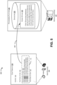
- FIG. 5 is a schematic diagram 500 illustrating an association 502 between a portion of code in a code template 504 (e.g., displayed via a user device 206) and coding options 506 that are made available for the portion of code via a particular programming platform 240 (e.g., optimal design patterns, best practices, etc.).
- An individual coding option 506 can include a description (e.g., the features, when the options should be used, etc.) and the actual code with which the code template 504 is to be populated, and the coding options 506 along with their descriptions and code are stored in a datastore 508 implemented via the service provider 204 and associated with the programming platform 240.
- the code template 504 comprises a function 510, and the function comprises: a first portion of code 512 (e.g., pre-populated source code of the code template 504), a second portion of code 514 (e.g., pre-populated source code of the code template 504), and a third portion of code 516 (e.g., pre-populated source code of the code template 504).
- a first portion of code 512 e.g., pre-populated source code of the code template 504
- a second portion of code 514 e.g., pre-populated source code of the code template 504
- a third portion of code 516 e.g., pre-populated source code of the code template 504.
- the code template can provide a visual distinction of a display area 518 in which the section portion of code 514 is displayed so the user is aware that a selection can be made, or must be made to finalize a code solution.
- the code template 504 can present the coding options in the display area 518.
- the code template 504 can provide a recommended coding option based on the recognized characteristics 230 of the diagram 228. For example, a first coding option in the display area 518 can be a "recommended" option. A second coding option in the display area 518 can be a "first alternative” recommended option. And a third coding option in the display area 518 can be a "second alternative" recommended option.
- the coding options presented in the code template 504 can be a subset of a larger set of coding options 506 made available via the programming platform 240.
- the coding options 506 can be evaluated and ordered based on their applicability to the characteristics of a particular design architecture. That is, the first coding option presented in the display area 518 may correspond to the recommended coding option stored in the datastore 508, the second coding option presented in the display area 518 may correspond to the first alternative recommended coding option stored in the datastore 508, and the third coding option presented in the display area 518 may correspond to the second alternative recommended coding option stored in the datastore 508. These first three coding options can be recommended in a particular order, as shown.
- the datastore 508 may also include a fourth coding option that is "not recommended” and/or a fifth coding option that would be "incompatible" with a particular design architecture. Based on the evaluation, the fourth coding option and/or the fifth coding option are not presented within the code template 504 for selection by a user.
- FIG. 6 is a flow diagram of an example process 600 to create a code template and associate the code template with particular characteristics of a drawn component (e.g., keywords, visual shape, visual relationship(s), etc.).
- the example process 600 can be implemented in association with various elements illustrated in FIGS. 1 and 2 .
- the example process 600 is not directly claimed and presented for illustrating purposes only.
- a code template for a programming language is created.
- a creator of the code template can write the code to serve as the pre-populated code when the code template is used for future development of computer programs.
- characteristics for the code template are defined.
- the creator of the code template can define keywords, visual shapes, and/or visual relationships, that if recognized in a diagram, can map a component of the diagram to the code template.
- a portion of code in the code template is associated with different coding options.
- the creator of the code template can determine that the portion of code can be implemented differently, and thus, can insert into the code template an instruction to (i) automatically select a coding option based on particular characteristics or (ii) access a programming platform 240 to identify the different coding options (e.g., in accordance with design patterns and best practices).
- the code template and the defined characteristics are stored together (e.g., in the datastore 226).
Landscapes
- Engineering & Computer Science (AREA)
- Software Systems (AREA)
- Theoretical Computer Science (AREA)
- General Engineering & Computer Science (AREA)
- Physics & Mathematics (AREA)
- General Physics & Mathematics (AREA)
- Computer Vision & Pattern Recognition (AREA)
- Artificial Intelligence (AREA)
- Multimedia (AREA)
- Stored Programmes (AREA)
Claims (13)
- Vorrichtung, umfassend:einen oder mehrere Prozessoren (212);Speicher (214); undein oder mehrere Module (218, 220, 222, 224), die in dem Speicher (214) gespeichert sind und von dem einen oder den mehreren Prozessoren (212) ausgeführt werden können zum:Empfangen (302) eines Diagramms (228), das eine Designarchitektur von mindestens einem Abschnitt eines Computerprogramms illustriert, wobei die Designarchitektur eine Vielzahl von Komponenten beinhaltet;Erkennen (304) von Merkmalen (230) der Vielzahl von Komponenten;Bestimmen (306), zumindest teilweise auf der Grundlage der Merkmale (230) der Vielzahl von Komponenten, einer Programmiersprache, für die Codevorlagen (238) in dem Speicher (214) gespeichert sind, und die mit der Designarchitektur verknüpft ist;für einzelne aus der Vielzahl von Komponenten, Verknüpfen (308) der Komponente mit einer oder mehreren Codevorlagen (238) zumindest teilweise auf der Grundlage der Merkmale (230), wobei eine einzelne Codevorlage (238) mit Quellcode der Programmiersprache vorausgefüllt ist;Bestimmen (402), auf der Grundlage der Merkmale (230), dass ein Abschnitt des Codes (514) in der einen oder den mehreren Codevorlagen (238) mit einer Vielzahl von verschiedenen Codieroptionen (506) verknüpft ist;Ordnen der Vielzahl verschiedener Codieroptionen (506), so dass eine erste geordnete Codieroption eine empfohlene Option ist und nachfolgende geordnete Codieroptionen alternative Optionen auf der Grundlage der Anwendbarkeit auf die Merkmale (230) der Designarchitektur sind, wobei die Vielzahl verschiedener Codieroptionen die neuesten und am häufigsten verwendeten Designmuster und/oder bewährten Verfahren widerspiegeln;Konfigurieren (404) der einen oder mehreren Codevorlagen (238) mit der Funktionalität, um mindestens zwei Codieroptionen (506) aus der Vielzahl verschiedener Codieroptionen (506) zu präsentieren und eine Auswahl der mindestens zwei Codieroptionen (506) zu ermöglichen; undVeranlassen (310), dass die eine oder die mehreren Codevorlagen (238) auf einer Vorrichtung (206) ausgegeben werden, die mit einem Benutzer verknüpft ist.
- Vorrichtung nach Anspruch 1, wobei das Diagramm (228) ein handgezeichnetes Diagramm (102) umfasst und die Merkmale der Vielzahl von Komponenten optisch erkannt werden.
- Vorrichtung nach Anspruch 1 oder Anspruch 2, wobei eine einzelne Komponente einen separaten oder einen modularen Teil des mindestens einen Abschnitts des Computerprogramms darstellt, der semantisch zugehörige Funktionalität enthält.
- Vorrichtung nach einem der Ansprüche 1 bis 3, wobei:die Merkmale (230) Schlüsselwörter umfassen, die die Vielzahl von Komponenten kennzeichnen oder benennen; unddie Komponente mit der einen oder den mehreren Codevorlagen (238) auf der Grundlage einer Zuordnung eines Schlüsselworts der Schlüsselwörter zu der einen oder den mehreren Codevorlagen (238) verknüpft ist.
- Vorrichtung nach einem der Ansprüche 1 bis 4, wobei:die Merkmale (230) visuelle Formen der Vielzahl von Komponenten umfassen; unddie Komponente mit der einen oder mehreren Codevorlagen (238) auf der Grundlage einer Zuordnung einer visuellen Form der visuellen Formen zu der einen oder den mehreren Codevorlagen (238) verknüpft ist.
- Vorrichtung nach einem der Ansprüche 1 bis 5, wobei:die Merkmale (230) visuelle Beziehungen zwischen der Vielzahl von Komponenten umfassen; unddie Komponente mit der einen oder mehreren Codevorlagen (238) auf der Grundlage einer Zuordnung einer visuellen Beziehung der visuellen Beziehungen zu der einen oder den mehreren Codevorlagen (238) verknüpft ist.
- Vorrichtung nach Anspruch 6, wobei die visuelle Beziehung eines der Folgenden umfasst:eine erste Komponente, die in dem Diagramm (228) visuell über einer zweiten Komponente dargestellt ist;eine visuelle Verbindung zwischen einer ersten Komponente und einer zweiten Komponente im Diagramm (228);eine visuelle Position einer ersten Komponente in einer Abfolge von Komponenten im Diagramm (228);eine erste visuelle Position einer ersten Komponente in dem Diagramm (228) im Vergleich zu einer zweiten visuellen Position einer zweiten Komponente in dem Diagramm (228); odereine Größe einer ersten Komponente im Vergleich zu einer Größe einer zweiten Komponente in dem Diagramm (228).
- Verfahren, umfassend:Empfangen (302) eines Diagramms (228), das eine Designarchitektur von mindestens einem Abschnitt eines Computerprogramms illustriert, wobei die Designarchitektur eine Vielzahl von Komponenten beinhaltet;Erkennen (304), durch einen oder mehrere Prozessoren (212), von Merkmalen (230) der Vielzahl von Komponenten;Bestimmen (306), zumindest teilweise auf der Grundlage der Merkmale (230) der Vielzahl von Komponenten, einer Programmiersprache, für die Codevorlagen (238) in einem Datenspeicher (226) gespeichert sind und die mit der Designarchitektur verknüpft ist;Verknüpfen (308) von einzelnen Komponenten aus der Vielzahl von Komponenten mit einer oder mehreren Codevorlagen (238) auf der Grundlage von zumindest teilweise den Merkmalen (230), wobei eine einzelne Codevorlage (238) mit Quellcode der Programmiersprache vorausgefüllt ist;Bestimmen (402), auf der Grundlage der Merkmale (230), dass ein Abschnitt des Codes (514) in der einen oder den mehreren Codevorlagen (238) mit einer Vielzahl von verschiedenen Codieroptionen (506) verknüpft ist;Ordnen der Vielzahl verschiedener Codieroptionen (506), so dass eine erste geordnete Codieroption (506) eine empfohlene Option ist und nachfolgende geordnete Codieroptionen (506) alternative Optionen auf der Grundlage der Anwendbarkeit auf die Merkmale (230) der Designarchitektur sind, wobei die Vielzahl verschiedener Codieroptionen die neuesten und am häufigsten verwendeten Designmuster und/oder bewährten Verfahren widerspiegeln;Konfigurieren (404) der einen oder mehreren Codevorlagen (238) mit der Funktionalität, um mindestens zwei Codieroptionen (506) aus der Vielzahl verschiedener Codieroptionen (506) zu präsentieren und eine Auswahl der mindestens zwei Codieroptionen (506) zu ermöglichen; undVeranlassen (310), dass die eine oder die mehreren Codevorlagen (238) auf einer Vorrichtung (206) ausgegeben werden, die mit einem Benutzer verknüpft ist.
- Verfahren nach Anspruch 8, weiter umfassend:Empfangen (312) einer Benutzereingabe von der Vorrichtung (206), die mit dem Benutzer verknüpft ist, die den Quellcode in der einen oder den mehreren Codevorlagen (238) aktualisiert; undAktualisieren (314) der einen oder mehreren Codevorlagen (238) zumindest teilweise auf der Grundlage der Benutzereingabe.
- Verfahren nach Anspruch 8 oder Anspruch 9, wobei:die Merkmale (230) Schlüsselwörter umfassen, die die Vielzahl von Komponenten kennzeichnen oder benennen; unddie Komponente mit der einen oder den mehreren Codevorlagen (238) auf der Grundlage einer Zuordnung eines Schlüsselworts der Schlüsselwörter zu der einen oder den mehreren Codevorlagen (238) verknüpft ist.
- Verfahren nach einem der Ansprüche 8 bis 10, wobei:die Merkmale (230) visuelle Formen der Vielzahl von Komponenten umfassen; unddie Komponente mit der einen oder mehreren Codevorlagen (238) auf der Grundlage einer Zuordnung einer visuellen Form der visuellen Formen zu der einen oder den mehreren Codevorlagen (238) verknüpft ist.
- Verfahren nach einem der Ansprüche 8 bis 11, wobei:die Merkmale (230) visuelle Beziehungen zwischen der Vielzahl von Komponenten umfassen; unddie Komponente mit der einen oder mehreren Codevorlagen (238) auf der Grundlage einer Zuordnung einer visuellen Beziehung der visuellen Beziehungen zu der einen oder den mehreren Codevorlagen (238) verknüpft ist.
- Ein oder mehrere Computerspeichermedien, die Anweisungen speichern, die, wenn sie von einem oder mehreren Prozessoren (212) ausgeführt werden, eine Vorrichtung zu Folgendem veranlassen:Empfangen (302) eines Diagramms (228), das eine Designarchitektur von mindestens einem Abschnitt (214) eines Computerprogramms illustriert, wobei die Designarchitektur eine Vielzahl von Komponenten beinhaltet;Erkennen (304) von Merkmalen (230) der Vielzahl der im Diagramm (228) illustrierten Komponenten;Bestimmen (306), zumindest teilweise auf der Grundlage der Merkmale (230) der Vielzahl von Komponenten, einer Programmiersprache, für die Codevorlagen (238) in einem Datenspeicher (226) gespeichert sind, die mit der Designarchitektur verknüpft ist;für einzelne der Vielzahl von Komponenten, Verwenden (308) der Merkmale (230), um die Komponente mit einer oder mehreren Codevorlagen (238) zu verknüpfen, wobei eine einzelne Codevorlage (238) mit Quellcode der Programmiersprache vorausgefüllt ist;Bestimmen (402), auf der Grundlage der Merkmale (230), dass ein Abschnitt des Codes (514) in der einen oder den mehreren Codevorlagen (238) mit einer Vielzahl von verschiedenen Codieroptionen (506) verknüpft ist;Ordnen der Vielzahl verschiedener Codieroptionen (506), so dass eine erste geordnete Codieroption eine empfohlene Option ist und nachfolgende geordnete Codieroptionen alternative Optionen auf der Grundlage der Anwendbarkeit auf die Merkmale (230) der Designarchitektur sind, wobei die Vielzahl verschiedener Codieroptionen die neuesten und am häufigsten verwendeten Designmuster und/oder bewährten Verfahren widerspiegeln;Konfigurieren (404) der einen oder mehreren Codevorlagen (238) mit der Funktionalität, um mindestens zwei Codieroptionen (506) aus der Vielzahl verschiedener Codieroptionen (506) zu präsentieren und eine Auswahl der mindestens zwei Codieroptionen (506) zu ermöglichen; undVeranlassen (310), dass die eine oder mehreren Codevorlagen (238) mit der Funktionalität auf einer Benutzervorrichtung (206) ausgegeben werden.
Applications Claiming Priority (2)
| Application Number | Priority Date | Filing Date | Title |
|---|---|---|---|
| US15/079,249 US10048946B2 (en) | 2016-03-24 | 2016-03-24 | Converting visual diagrams into code |
| PCT/US2017/023119 WO2017165249A1 (en) | 2016-03-24 | 2017-03-20 | Converting visual diagrams into code |
Publications (2)
| Publication Number | Publication Date |
|---|---|
| EP3433732A1 EP3433732A1 (de) | 2019-01-30 |
| EP3433732B1 true EP3433732B1 (de) | 2023-12-20 |
Family
ID=58461484
Family Applications (1)
| Application Number | Title | Priority Date | Filing Date |
|---|---|---|---|
| EP17714990.3A Active EP3433732B1 (de) | 2016-03-24 | 2017-03-20 | Umwandlung visueller diagramme in code |
Country Status (4)
| Country | Link |
|---|---|
| US (2) | US10048946B2 (de) |
| EP (1) | EP3433732B1 (de) |
| CN (1) | CN109074245A (de) |
| WO (1) | WO2017165249A1 (de) |
Families Citing this family (28)
| Publication number | Priority date | Publication date | Assignee | Title |
|---|---|---|---|---|
| US10838699B2 (en) | 2017-01-18 | 2020-11-17 | Oracle International Corporation | Generating data mappings for user interface screens and screen components for an application |
| US10733754B2 (en) | 2017-01-18 | 2020-08-04 | Oracle International Corporation | Generating a graphical user interface model from an image |
| US11645046B2 (en) * | 2017-07-03 | 2023-05-09 | Unqork, Inc. | Systems and methods for development and deployment of software platforms having advanced workflow and event processing components |
| US10782939B2 (en) * | 2017-08-07 | 2020-09-22 | Microsoft Technology Licensing, Llc | Program predictor |
| CN108021363B (zh) * | 2017-12-06 | 2021-06-15 | 广州多益网络股份有限公司 | 可视化游戏逻辑编辑方法及系统 |
| US10481879B2 (en) * | 2018-02-07 | 2019-11-19 | Microsoft Technology Licensing, Llc | Code development using continued machine learnings |
| US10489126B2 (en) | 2018-02-12 | 2019-11-26 | Oracle International Corporation | Automated code generation |
| US12353389B2 (en) * | 2018-03-30 | 2025-07-08 | Databricks, Inc. | Customized code configurations for a multiple application service environment |
| US10942709B2 (en) | 2019-07-02 | 2021-03-09 | Holtworks, LLC | Hyperpiler |
| US12493451B1 (en) | 2019-07-02 | 2025-12-09 | Holtwork LLC | Hyperplexer |
| US10853062B1 (en) | 2019-07-02 | 2020-12-01 | Holtworks, LLC | Hyperpiler |
| CN112230910B (zh) * | 2019-07-15 | 2023-09-15 | 腾讯科技(深圳)有限公司 | 嵌入型程序的页面生成方法、装置、设备及存储介质 |
| US11372380B2 (en) | 2019-10-15 | 2022-06-28 | UiPath, Inc. | Media-to-workflow generation using artificial intelligence (AI) |
| CN110968299A (zh) * | 2019-11-20 | 2020-04-07 | 北京工业大学 | 一种基于手绘网页图像的前端工程化代码生成方法 |
| US11204690B1 (en) | 2020-03-05 | 2021-12-21 | Unqork, Inc. | Systems and methods for software development and deployment platforms having advanced workflow and event processing capabilities and graphical version controls |
| US11221833B1 (en) * | 2020-03-18 | 2022-01-11 | Amazon Technologies, Inc. | Automated object detection for user interface generation |
| CN113535151B (zh) * | 2020-04-14 | 2024-05-17 | 北京京东振世信息技术有限公司 | 代码生成方法和装置 |
| US11797428B2 (en) * | 2020-05-07 | 2023-10-24 | Mitel Networks Corporation | Dynamic user interface testing and reconciliation |
| CN112114790B (zh) * | 2020-08-28 | 2024-09-20 | 浪潮通用软件有限公司 | 一种基于概念数据模型的领域代码生成方法及装置 |
| EP4290366A4 (de) * | 2021-02-04 | 2024-10-16 | Telefónica Innovación Digital, S.L.U. | Implementierung eines computerprojekts auf der basis einer designkontur |
| CN113238752B (zh) * | 2021-05-17 | 2024-09-20 | 北京达佳互联信息技术有限公司 | 代码生成方法、装置、电子设备及存储介质 |
| US11663761B2 (en) * | 2021-08-25 | 2023-05-30 | Sap Se | Hand-drawn diagram recognition using visual arrow-relation detection |
| US12197897B2 (en) * | 2022-07-21 | 2025-01-14 | Microsoft Technology Licensing, Llc | Image-based infrastructure-as-code processing based on predicted context |
| US12461721B2 (en) * | 2022-11-04 | 2025-11-04 | Delany Group, Llc | System and methods for automated API determination, generation, and integration |
| CN116385726A (zh) * | 2023-02-09 | 2023-07-04 | 北京天兵科技有限公司 | 一种基于图像识别的飞行时序生成方法、装置和设备 |
| CN116610304B (zh) * | 2023-07-18 | 2024-01-02 | 腾讯科技(深圳)有限公司 | 页面代码生成方法、装置、设备和存储介质 |
| CN116700702B (zh) * | 2023-08-08 | 2023-10-03 | 福州兴趣马力科技有限公司 | 一种手绘卡片的编程方法、系统、设备及介质 |
| US20250315216A1 (en) * | 2024-04-08 | 2025-10-09 | International Business Machines Corporation | Policy controlled function generators |
Family Cites Families (39)
| Publication number | Priority date | Publication date | Assignee | Title |
|---|---|---|---|---|
| JPH0772861B2 (ja) * | 1990-08-24 | 1995-08-02 | 富士ゼロックス株式会社 | プログラム作成装置 |
| US6742175B1 (en) * | 1998-10-13 | 2004-05-25 | Codagen Technologies Corp. | Component-based source code generator |
| US7322524B2 (en) | 2000-10-20 | 2008-01-29 | Silverbrook Research Pty Ltd | Graphic design software using an interface surface |
| EP1277104A1 (de) | 2000-03-30 | 2003-01-22 | Ideogramic APS | Verfahren zur modellierung auf gestenbasis |
| US20040015809A1 (en) * | 2001-05-18 | 2004-01-22 | Doreen Yining Cheng | Code generation for integrating devices into a middleware framework |
| US8522196B1 (en) * | 2001-10-25 | 2013-08-27 | The Mathworks, Inc. | Traceability in a modeling environment |
| US7849394B2 (en) * | 2001-10-25 | 2010-12-07 | The Math Works, Inc. | Linked code generation report |
| US20050044527A1 (en) * | 2003-08-22 | 2005-02-24 | Gerardo Recinto | Code Units based Framework for domain- independent Visual Design and Development |
| US7324691B2 (en) | 2003-09-24 | 2008-01-29 | Microsoft Corporation | System and method for shape recognition of hand-drawn objects |
| GB0410047D0 (en) | 2004-05-05 | 2004-06-09 | Silverdata Ltd | An analytical software design system |
| WO2006043012A1 (en) * | 2004-10-22 | 2006-04-27 | New Technology/Enterprise Limited | Data processing system and method |
| US8086998B2 (en) | 2006-04-27 | 2011-12-27 | International Business Machines Corporation | transforming meta object facility specifications into relational data definition language structures and JAVA classes |
| KR20080002084A (ko) * | 2006-06-30 | 2008-01-04 | 삼성전자주식회사 | 광학 문자 판독을 위한 시스템 및 광학 문자 판독방법 |
| US7900188B2 (en) * | 2006-09-01 | 2011-03-01 | The Mathworks, Inc. | Specifying implementations of code for code generation from a model |
| CN100520716C (zh) * | 2007-08-28 | 2009-07-29 | 北京中企开源信息技术有限公司 | 一种基于模型组件的代码自动生成装置、系统及方法 |
| US20090064092A1 (en) * | 2007-08-29 | 2009-03-05 | Microsoft Corporation | Visual programming language optimization |
| US8656349B2 (en) * | 2008-03-07 | 2014-02-18 | Sap Ag | Systems and methods for template reverse engineering |
| CN101256492A (zh) * | 2008-03-31 | 2008-09-03 | 宋乃辉 | 一种进行模型驱动架构的软件开发方法及其系统 |
| US8584085B2 (en) | 2008-09-24 | 2013-11-12 | Accenture Global Services Limited | Identification of concepts in software |
| US8327316B2 (en) * | 2008-09-30 | 2012-12-04 | Ics Triplex Isagraf Inc. | Compilation model |
| JP2010198494A (ja) * | 2009-02-26 | 2010-09-09 | Panasonic Corp | ソフトウェア開発支援ツール |
| US8495560B2 (en) | 2009-10-12 | 2013-07-23 | International Business Machines Corporation | Converting an activity diagram into code |
| US20110088011A1 (en) * | 2009-10-14 | 2011-04-14 | Vermeg Sarl | Automated Enterprise Software Development |
| US8607190B2 (en) | 2009-10-23 | 2013-12-10 | International Business Machines Corporation | Automation of software application engineering using machine learning and reasoning |
| US20110137872A1 (en) * | 2009-12-04 | 2011-06-09 | International Business Machines Corporation | Model-driven data archival system having automated components |
| US8713540B2 (en) * | 2010-07-29 | 2014-04-29 | National Instruments Corporation | Generating and modifying textual code interfaces from graphical programs |
| US9015011B2 (en) | 2011-01-25 | 2015-04-21 | Accenture Global Services Limited | Assistant tool |
| US8972928B2 (en) * | 2011-08-30 | 2015-03-03 | Uniquesoft, Llc | System and method for generating application code |
| US20130097583A1 (en) | 2011-09-27 | 2013-04-18 | The University Of Texas System | Systems and Methods For Automating the Application of a Software Methodology |
| CN102662651A (zh) * | 2012-03-08 | 2012-09-12 | 北京神州数码思特奇信息技术股份有限公司 | 可视化组件的生成方法和生成模块 |
| US20140214396A1 (en) * | 2013-01-28 | 2014-07-31 | International Business Machines Corporation | Specification properties creation for a visual model of a system |
| US20140282369A1 (en) | 2013-03-14 | 2014-09-18 | Adminovate, Inc. | Software application generator |
| US9269076B2 (en) * | 2013-03-15 | 2016-02-23 | International Business Machines Corporation | Techniques to facilitate collaborative social coding |
| US9223547B1 (en) * | 2013-04-02 | 2015-12-29 | Amazon Technologies, Inc. | Audio input for structured languages |
| US9501594B2 (en) | 2014-04-13 | 2016-11-22 | Vtool Ltd. | Graphical design verification environment generator |
| US10191889B2 (en) * | 2014-07-29 | 2019-01-29 | Board Of Regents, The University Of Texas System | Systems, apparatuses and methods for generating a user interface by performing computer vision and optical character recognition on a graphical representation |
| US20160041815A1 (en) * | 2014-08-11 | 2016-02-11 | Chirag P. Bhagat | Computer Source Code Generator for Building Software Applications |
| US9530102B2 (en) * | 2015-02-17 | 2016-12-27 | The Mathworks, Inc. | Multimodal input processing |
| US9898260B2 (en) * | 2015-12-28 | 2018-02-20 | Samsung Electronics Co., Ltd. | Adaptive function-based dynamic application extension framework |
-
2016
- 2016-03-24 US US15/079,249 patent/US10048946B2/en active Active
-
2017
- 2017-03-20 CN CN201780019149.6A patent/CN109074245A/zh active Pending
- 2017-03-20 WO PCT/US2017/023119 patent/WO2017165249A1/en not_active Ceased
- 2017-03-20 EP EP17714990.3A patent/EP3433732B1/de active Active
-
2018
- 2018-07-20 US US16/041,450 patent/US10579344B2/en active Active
Also Published As
| Publication number | Publication date |
|---|---|
| US20180329690A1 (en) | 2018-11-15 |
| US10579344B2 (en) | 2020-03-03 |
| CN109074245A (zh) | 2018-12-21 |
| WO2017165249A1 (en) | 2017-09-28 |
| EP3433732A1 (de) | 2019-01-30 |
| US20170277518A1 (en) | 2017-09-28 |
| US10048946B2 (en) | 2018-08-14 |
Similar Documents
| Publication | Publication Date | Title |
|---|---|---|
| EP3433732B1 (de) | Umwandlung visueller diagramme in code | |
| US11221833B1 (en) | Automated object detection for user interface generation | |
| CN108762743B (zh) | 一种数据表操作代码生成方法及装置 | |
| WO2020140940A1 (zh) | 代码的生成方法、装置、设备及存储介质 | |
| US12505028B2 (en) | Automatic generation of test scenarios from specification files | |
| CN119917087B (zh) | 前端页面搭建方法、装置、电子设备、存储介质及产品 | |
| US10776351B2 (en) | Automatic core data service view generator | |
| WO2024244727A1 (zh) | 一种应用打包方法、装置、设备及存储介质 | |
| CN113094776B (zh) | 可视化组件模型数据构建的方法、系统及电子设备 | |
| CN119396375A (zh) | 一种接口文档自动生成方法及其相关设备 | |
| CN116643755B (zh) | 代码生成方法、代码生成装置、可视化平台及电子设备 | |
| Rosales-Morales et al. | ImagIngDev: a new approach for developing automatic cross-platform mobile applications using image processing techniques | |
| US10656921B2 (en) | Sparse object instantiation | |
| CN120255951A (zh) | 一种基于java应用生成接口文档的方法及系统 | |
| KR102651294B1 (ko) | 화면 구성 요소에 대한 정보 수집을 지원하는 방법 | |
| CN119127285A (zh) | 一种软件工具包开发方法、装置、计算机设备及存储介质 | |
| US11977473B2 (en) | Providing a pseudo language for manipulating complex variables of an orchestration flow | |
| CN109343871A (zh) | 应用程序打包的方法、装置、设备及存储介质 | |
| CN114579466A (zh) | 构建测试用例和代码测试的方法、装置、设备及介质 | |
| Böhm | AI-Assisted coding and comparative performance analysis of cross-platform mobile applications: kotlin multiplatform Vs. react native | |
| Winnie | Essential Java for AP CompSci | |
| Chandrashekar et al. | From Diagrams to Code: An Exploration into Automated Cloud Template Creation | |
| CN120085910A (zh) | 文件处理方法、装置、设备和介质 | |
| CN120632031A (zh) | 用于生成提示词的方法、装置、设备、介质及程序产品 | |
| CN118259874A (zh) | 一种产品设计的分析方法、系统和电子设备 |
Legal Events
| Date | Code | Title | Description |
|---|---|---|---|
| STAA | Information on the status of an ep patent application or granted ep patent |
Free format text: STATUS: UNKNOWN |
|
| STAA | Information on the status of an ep patent application or granted ep patent |
Free format text: STATUS: THE INTERNATIONAL PUBLICATION HAS BEEN MADE |
|
| PUAI | Public reference made under article 153(3) epc to a published international application that has entered the european phase |
Free format text: ORIGINAL CODE: 0009012 |
|
| STAA | Information on the status of an ep patent application or granted ep patent |
Free format text: STATUS: REQUEST FOR EXAMINATION WAS MADE |
|
| 17P | Request for examination filed |
Effective date: 20180921 |
|
| AK | Designated contracting states |
Kind code of ref document: A1 Designated state(s): AL AT BE BG CH CY CZ DE DK EE ES FI FR GB GR HR HU IE IS IT LI LT LU LV MC MK MT NL NO PL PT RO RS SE SI SK SM TR |
|
| AX | Request for extension of the european patent |
Extension state: BA ME |
|
| DAV | Request for validation of the european patent (deleted) | ||
| DAX | Request for extension of the european patent (deleted) | ||
| STAA | Information on the status of an ep patent application or granted ep patent |
Free format text: STATUS: EXAMINATION IS IN PROGRESS |
|
| 17Q | First examination report despatched |
Effective date: 20210510 |
|
| RAP3 | Party data changed (applicant data changed or rights of an application transferred) |
Owner name: MICROSOFT TECHNOLOGY LICENSING, LLC |
|
| REG | Reference to a national code |
Ref legal event code: R079 Ipc: G06F0008340000 Ref country code: DE Ref legal event code: R079 Ref document number: 602017077669 Country of ref document: DE Free format text: PREVIOUS MAIN CLASS: G06F0009440000 Ipc: G06F0008340000 |
|
| GRAP | Despatch of communication of intention to grant a patent |
Free format text: ORIGINAL CODE: EPIDOSNIGR1 |
|
| STAA | Information on the status of an ep patent application or granted ep patent |
Free format text: STATUS: GRANT OF PATENT IS INTENDED |
|
| RIC1 | Information provided on ipc code assigned before grant |
Ipc: G06V 30/422 20220101ALI20230627BHEP Ipc: G06F 8/35 20180101ALI20230627BHEP Ipc: G06F 8/34 20180101AFI20230627BHEP |
|
| INTG | Intention to grant announced |
Effective date: 20230720 |
|
| GRAS | Grant fee paid |
Free format text: ORIGINAL CODE: EPIDOSNIGR3 |
|
| GRAA | (expected) grant |
Free format text: ORIGINAL CODE: 0009210 |
|
| STAA | Information on the status of an ep patent application or granted ep patent |
Free format text: STATUS: THE PATENT HAS BEEN GRANTED |
|
| P01 | Opt-out of the competence of the unified patent court (upc) registered |
Effective date: 20231029 |
|
| AK | Designated contracting states |
Kind code of ref document: B1 Designated state(s): AL AT BE BG CH CY CZ DE DK EE ES FI FR GB GR HR HU IE IS IT LI LT LU LV MC MK MT NL NO PL PT RO RS SE SI SK SM TR |
|
| REG | Reference to a national code |
Ref country code: GB Ref legal event code: FG4D |
|
| REG | Reference to a national code |
Ref country code: CH Ref legal event code: EP |
|
| REG | Reference to a national code |
Ref country code: DE Ref legal event code: R096 Ref document number: 602017077669 Country of ref document: DE |
|
| REG | Reference to a national code |
Ref country code: IE Ref legal event code: FG4D |
|
| PG25 | Lapsed in a contracting state [announced via postgrant information from national office to epo] |
Ref country code: GR Free format text: LAPSE BECAUSE OF FAILURE TO SUBMIT A TRANSLATION OF THE DESCRIPTION OR TO PAY THE FEE WITHIN THE PRESCRIBED TIME-LIMIT Effective date: 20240321 |
|
| REG | Reference to a national code |
Ref country code: LT Ref legal event code: MG9D |
|
| PG25 | Lapsed in a contracting state [announced via postgrant information from national office to epo] |
Ref country code: LT Free format text: LAPSE BECAUSE OF FAILURE TO SUBMIT A TRANSLATION OF THE DESCRIPTION OR TO PAY THE FEE WITHIN THE PRESCRIBED TIME-LIMIT Effective date: 20231220 |
|
| REG | Reference to a national code |
Ref country code: NL Ref legal event code: MP Effective date: 20231220 |
|
| PG25 | Lapsed in a contracting state [announced via postgrant information from national office to epo] |
Ref country code: ES Free format text: LAPSE BECAUSE OF FAILURE TO SUBMIT A TRANSLATION OF THE DESCRIPTION OR TO PAY THE FEE WITHIN THE PRESCRIBED TIME-LIMIT Effective date: 20231220 |
|
| PG25 | Lapsed in a contracting state [announced via postgrant information from national office to epo] |
Ref country code: LT Free format text: LAPSE BECAUSE OF FAILURE TO SUBMIT A TRANSLATION OF THE DESCRIPTION OR TO PAY THE FEE WITHIN THE PRESCRIBED TIME-LIMIT Effective date: 20231220 Ref country code: GR Free format text: LAPSE BECAUSE OF FAILURE TO SUBMIT A TRANSLATION OF THE DESCRIPTION OR TO PAY THE FEE WITHIN THE PRESCRIBED TIME-LIMIT Effective date: 20240321 Ref country code: FI Free format text: LAPSE BECAUSE OF FAILURE TO SUBMIT A TRANSLATION OF THE DESCRIPTION OR TO PAY THE FEE WITHIN THE PRESCRIBED TIME-LIMIT Effective date: 20231220 Ref country code: ES Free format text: LAPSE BECAUSE OF FAILURE TO SUBMIT A TRANSLATION OF THE DESCRIPTION OR TO PAY THE FEE WITHIN THE PRESCRIBED TIME-LIMIT Effective date: 20231220 Ref country code: BG Free format text: LAPSE BECAUSE OF FAILURE TO SUBMIT A TRANSLATION OF THE DESCRIPTION OR TO PAY THE FEE WITHIN THE PRESCRIBED TIME-LIMIT Effective date: 20240320 |
|
| REG | Reference to a national code |
Ref country code: AT Ref legal event code: MK05 Ref document number: 1643040 Country of ref document: AT Kind code of ref document: T Effective date: 20231220 |
|
| PG25 | Lapsed in a contracting state [announced via postgrant information from national office to epo] |
Ref country code: NL Free format text: LAPSE BECAUSE OF FAILURE TO SUBMIT A TRANSLATION OF THE DESCRIPTION OR TO PAY THE FEE WITHIN THE PRESCRIBED TIME-LIMIT Effective date: 20231220 |
|
| PG25 | Lapsed in a contracting state [announced via postgrant information from national office to epo] |
Ref country code: SE Free format text: LAPSE BECAUSE OF FAILURE TO SUBMIT A TRANSLATION OF THE DESCRIPTION OR TO PAY THE FEE WITHIN THE PRESCRIBED TIME-LIMIT Effective date: 20231220 Ref country code: RS Free format text: LAPSE BECAUSE OF FAILURE TO SUBMIT A TRANSLATION OF THE DESCRIPTION OR TO PAY THE FEE WITHIN THE PRESCRIBED TIME-LIMIT Effective date: 20231220 Ref country code: NO Free format text: LAPSE BECAUSE OF FAILURE TO SUBMIT A TRANSLATION OF THE DESCRIPTION OR TO PAY THE FEE WITHIN THE PRESCRIBED TIME-LIMIT Effective date: 20240320 Ref country code: NL Free format text: LAPSE BECAUSE OF FAILURE TO SUBMIT A TRANSLATION OF THE DESCRIPTION OR TO PAY THE FEE WITHIN THE PRESCRIBED TIME-LIMIT Effective date: 20231220 Ref country code: LV Free format text: LAPSE BECAUSE OF FAILURE TO SUBMIT A TRANSLATION OF THE DESCRIPTION OR TO PAY THE FEE WITHIN THE PRESCRIBED TIME-LIMIT Effective date: 20231220 Ref country code: HR Free format text: LAPSE BECAUSE OF FAILURE TO SUBMIT A TRANSLATION OF THE DESCRIPTION OR TO PAY THE FEE WITHIN THE PRESCRIBED TIME-LIMIT Effective date: 20231220 |
|
| PG25 | Lapsed in a contracting state [announced via postgrant information from national office to epo] |
Ref country code: IS Free format text: LAPSE BECAUSE OF FAILURE TO SUBMIT A TRANSLATION OF THE DESCRIPTION OR TO PAY THE FEE WITHIN THE PRESCRIBED TIME-LIMIT Effective date: 20240420 |
|
| PG25 | Lapsed in a contracting state [announced via postgrant information from national office to epo] |
Ref country code: CZ Free format text: LAPSE BECAUSE OF FAILURE TO SUBMIT A TRANSLATION OF THE DESCRIPTION OR TO PAY THE FEE WITHIN THE PRESCRIBED TIME-LIMIT Effective date: 20231220 Ref country code: AT Free format text: LAPSE BECAUSE OF FAILURE TO SUBMIT A TRANSLATION OF THE DESCRIPTION OR TO PAY THE FEE WITHIN THE PRESCRIBED TIME-LIMIT Effective date: 20231220 |
|
| PG25 | Lapsed in a contracting state [announced via postgrant information from national office to epo] |
Ref country code: SK Free format text: LAPSE BECAUSE OF FAILURE TO SUBMIT A TRANSLATION OF THE DESCRIPTION OR TO PAY THE FEE WITHIN THE PRESCRIBED TIME-LIMIT Effective date: 20231220 |
|
| PG25 | Lapsed in a contracting state [announced via postgrant information from national office to epo] |
Ref country code: SM Free format text: LAPSE BECAUSE OF FAILURE TO SUBMIT A TRANSLATION OF THE DESCRIPTION OR TO PAY THE FEE WITHIN THE PRESCRIBED TIME-LIMIT Effective date: 20231220 Ref country code: SK Free format text: LAPSE BECAUSE OF FAILURE TO SUBMIT A TRANSLATION OF THE DESCRIPTION OR TO PAY THE FEE WITHIN THE PRESCRIBED TIME-LIMIT Effective date: 20231220 Ref country code: RO Free format text: LAPSE BECAUSE OF FAILURE TO SUBMIT A TRANSLATION OF THE DESCRIPTION OR TO PAY THE FEE WITHIN THE PRESCRIBED TIME-LIMIT Effective date: 20231220 Ref country code: IT Free format text: LAPSE BECAUSE OF FAILURE TO SUBMIT A TRANSLATION OF THE DESCRIPTION OR TO PAY THE FEE WITHIN THE PRESCRIBED TIME-LIMIT Effective date: 20231220 Ref country code: IS Free format text: LAPSE BECAUSE OF FAILURE TO SUBMIT A TRANSLATION OF THE DESCRIPTION OR TO PAY THE FEE WITHIN THE PRESCRIBED TIME-LIMIT Effective date: 20240420 Ref country code: EE Free format text: LAPSE BECAUSE OF FAILURE TO SUBMIT A TRANSLATION OF THE DESCRIPTION OR TO PAY THE FEE WITHIN THE PRESCRIBED TIME-LIMIT Effective date: 20231220 Ref country code: CZ Free format text: LAPSE BECAUSE OF FAILURE TO SUBMIT A TRANSLATION OF THE DESCRIPTION OR TO PAY THE FEE WITHIN THE PRESCRIBED TIME-LIMIT Effective date: 20231220 Ref country code: AT Free format text: LAPSE BECAUSE OF FAILURE TO SUBMIT A TRANSLATION OF THE DESCRIPTION OR TO PAY THE FEE WITHIN THE PRESCRIBED TIME-LIMIT Effective date: 20231220 |
|
| PG25 | Lapsed in a contracting state [announced via postgrant information from national office to epo] |
Ref country code: PL Free format text: LAPSE BECAUSE OF FAILURE TO SUBMIT A TRANSLATION OF THE DESCRIPTION OR TO PAY THE FEE WITHIN THE PRESCRIBED TIME-LIMIT Effective date: 20231220 Ref country code: PT Free format text: LAPSE BECAUSE OF FAILURE TO SUBMIT A TRANSLATION OF THE DESCRIPTION OR TO PAY THE FEE WITHIN THE PRESCRIBED TIME-LIMIT Effective date: 20240422 |
|
| PG25 | Lapsed in a contracting state [announced via postgrant information from national office to epo] |
Ref country code: PT Free format text: LAPSE BECAUSE OF FAILURE TO SUBMIT A TRANSLATION OF THE DESCRIPTION OR TO PAY THE FEE WITHIN THE PRESCRIBED TIME-LIMIT Effective date: 20240422 Ref country code: PL Free format text: LAPSE BECAUSE OF FAILURE TO SUBMIT A TRANSLATION OF THE DESCRIPTION OR TO PAY THE FEE WITHIN THE PRESCRIBED TIME-LIMIT Effective date: 20231220 |
|
| REG | Reference to a national code |
Ref country code: DE Ref legal event code: R097 Ref document number: 602017077669 Country of ref document: DE |
|
| PG25 | Lapsed in a contracting state [announced via postgrant information from national office to epo] |
Ref country code: DK Free format text: LAPSE BECAUSE OF FAILURE TO SUBMIT A TRANSLATION OF THE DESCRIPTION OR TO PAY THE FEE WITHIN THE PRESCRIBED TIME-LIMIT Effective date: 20231220 |
|
| PLBE | No opposition filed within time limit |
Free format text: ORIGINAL CODE: 0009261 |
|
| STAA | Information on the status of an ep patent application or granted ep patent |
Free format text: STATUS: NO OPPOSITION FILED WITHIN TIME LIMIT |
|
| PG25 | Lapsed in a contracting state [announced via postgrant information from national office to epo] |
Ref country code: SI Free format text: LAPSE BECAUSE OF FAILURE TO SUBMIT A TRANSLATION OF THE DESCRIPTION OR TO PAY THE FEE WITHIN THE PRESCRIBED TIME-LIMIT Effective date: 20231220 |
|
| PG25 | Lapsed in a contracting state [announced via postgrant information from national office to epo] |
Ref country code: SI Free format text: LAPSE BECAUSE OF FAILURE TO SUBMIT A TRANSLATION OF THE DESCRIPTION OR TO PAY THE FEE WITHIN THE PRESCRIBED TIME-LIMIT Effective date: 20231220 Ref country code: DK Free format text: LAPSE BECAUSE OF FAILURE TO SUBMIT A TRANSLATION OF THE DESCRIPTION OR TO PAY THE FEE WITHIN THE PRESCRIBED TIME-LIMIT Effective date: 20231220 |
|
| REG | Reference to a national code |
Ref country code: CH Ref legal event code: PL |
|
| PG25 | Lapsed in a contracting state [announced via postgrant information from national office to epo] |
Ref country code: LU Free format text: LAPSE BECAUSE OF NON-PAYMENT OF DUE FEES Effective date: 20240320 |
|
| PG25 | Lapsed in a contracting state [announced via postgrant information from national office to epo] |
Ref country code: MC Free format text: LAPSE BECAUSE OF FAILURE TO SUBMIT A TRANSLATION OF THE DESCRIPTION OR TO PAY THE FEE WITHIN THE PRESCRIBED TIME-LIMIT Effective date: 20231220 |
|
| 26N | No opposition filed |
Effective date: 20240923 |
|
| PG25 | Lapsed in a contracting state [announced via postgrant information from national office to epo] |
Ref country code: MC Free format text: LAPSE BECAUSE OF FAILURE TO SUBMIT A TRANSLATION OF THE DESCRIPTION OR TO PAY THE FEE WITHIN THE PRESCRIBED TIME-LIMIT Effective date: 20231220 Ref country code: LU Free format text: LAPSE BECAUSE OF NON-PAYMENT OF DUE FEES Effective date: 20240320 |
|
| REG | Reference to a national code |
Ref country code: BE Ref legal event code: MM Effective date: 20240331 |
|
| PG25 | Lapsed in a contracting state [announced via postgrant information from national office to epo] |
Ref country code: BE Free format text: LAPSE BECAUSE OF NON-PAYMENT OF DUE FEES Effective date: 20240331 |
|
| PG25 | Lapsed in a contracting state [announced via postgrant information from national office to epo] |
Ref country code: IE Free format text: LAPSE BECAUSE OF NON-PAYMENT OF DUE FEES Effective date: 20240320 |
|
| PG25 | Lapsed in a contracting state [announced via postgrant information from national office to epo] |
Ref country code: IE Free format text: LAPSE BECAUSE OF NON-PAYMENT OF DUE FEES Effective date: 20240320 Ref country code: BE Free format text: LAPSE BECAUSE OF NON-PAYMENT OF DUE FEES Effective date: 20240331 Ref country code: CH Free format text: LAPSE BECAUSE OF NON-PAYMENT OF DUE FEES Effective date: 20240331 |
|
| PGFP | Annual fee paid to national office [announced via postgrant information from national office to epo] |
Ref country code: DE Payment date: 20250218 Year of fee payment: 9 |
|
| PGFP | Annual fee paid to national office [announced via postgrant information from national office to epo] |
Ref country code: FR Payment date: 20250218 Year of fee payment: 9 |
|
| PGFP | Annual fee paid to national office [announced via postgrant information from national office to epo] |
Ref country code: GB Payment date: 20250221 Year of fee payment: 9 |
|
| PG25 | Lapsed in a contracting state [announced via postgrant information from national office to epo] |
Ref country code: CY Free format text: LAPSE BECAUSE OF FAILURE TO SUBMIT A TRANSLATION OF THE DESCRIPTION OR TO PAY THE FEE WITHIN THE PRESCRIBED TIME-LIMIT; INVALID AB INITIO Effective date: 20170320 |
|
| PG25 | Lapsed in a contracting state [announced via postgrant information from national office to epo] |
Ref country code: HU Free format text: LAPSE BECAUSE OF FAILURE TO SUBMIT A TRANSLATION OF THE DESCRIPTION OR TO PAY THE FEE WITHIN THE PRESCRIBED TIME-LIMIT; INVALID AB INITIO Effective date: 20170320 |
|
| PG25 | Lapsed in a contracting state [announced via postgrant information from national office to epo] |
Ref country code: TR Free format text: LAPSE BECAUSE OF FAILURE TO SUBMIT A TRANSLATION OF THE DESCRIPTION OR TO PAY THE FEE WITHIN THE PRESCRIBED TIME-LIMIT Effective date: 20231220 |