EP4290158A1 - Refrigeration cycle device - Google Patents
Refrigeration cycle device Download PDFInfo
- Publication number
- EP4290158A1 EP4290158A1 EP21924550.3A EP21924550A EP4290158A1 EP 4290158 A1 EP4290158 A1 EP 4290158A1 EP 21924550 A EP21924550 A EP 21924550A EP 4290158 A1 EP4290158 A1 EP 4290158A1
- Authority
- EP
- European Patent Office
- Prior art keywords
- refrigerant
- heat exchanger
- evaporator
- temperature
- expansion valve
- Prior art date
- Legal status (The legal status is an assumption and is not a legal conclusion. Google has not performed a legal analysis and makes no representation as to the accuracy of the status listed.)
- Granted
Links
Images









Classifications
-
- F—MECHANICAL ENGINEERING; LIGHTING; HEATING; WEAPONS; BLASTING
- F25—REFRIGERATION OR COOLING; COMBINED HEATING AND REFRIGERATION SYSTEMS; HEAT PUMP SYSTEMS; MANUFACTURE OR STORAGE OF ICE; LIQUEFACTION SOLIDIFICATION OF GASES
- F25B—REFRIGERATION MACHINES, PLANTS OR SYSTEMS; COMBINED HEATING AND REFRIGERATION SYSTEMS; HEAT PUMP SYSTEMS
- F25B49/00—Arrangement or mounting of control or safety devices
- F25B49/02—Arrangement or mounting of control or safety devices for compression type machines, plants or systems
-
- F—MECHANICAL ENGINEERING; LIGHTING; HEATING; WEAPONS; BLASTING
- F25—REFRIGERATION OR COOLING; COMBINED HEATING AND REFRIGERATION SYSTEMS; HEAT PUMP SYSTEMS; MANUFACTURE OR STORAGE OF ICE; LIQUEFACTION SOLIDIFICATION OF GASES
- F25B—REFRIGERATION MACHINES, PLANTS OR SYSTEMS; COMBINED HEATING AND REFRIGERATION SYSTEMS; HEAT PUMP SYSTEMS
- F25B41/00—Fluid-circulation arrangements
- F25B41/30—Expansion means; Dispositions thereof
- F25B41/31—Expansion valves
-
- F—MECHANICAL ENGINEERING; LIGHTING; HEATING; WEAPONS; BLASTING
- F25—REFRIGERATION OR COOLING; COMBINED HEATING AND REFRIGERATION SYSTEMS; HEAT PUMP SYSTEMS; MANUFACTURE OR STORAGE OF ICE; LIQUEFACTION SOLIDIFICATION OF GASES
- F25B—REFRIGERATION MACHINES, PLANTS OR SYSTEMS; COMBINED HEATING AND REFRIGERATION SYSTEMS; HEAT PUMP SYSTEMS
- F25B47/00—Arrangements for preventing or removing deposits or corrosion, not provided for in another subclass
- F25B47/006—Arrangements for preventing or removing deposits or corrosion, not provided for in another subclass for preventing frost
-
- F—MECHANICAL ENGINEERING; LIGHTING; HEATING; WEAPONS; BLASTING
- F25—REFRIGERATION OR COOLING; COMBINED HEATING AND REFRIGERATION SYSTEMS; HEAT PUMP SYSTEMS; MANUFACTURE OR STORAGE OF ICE; LIQUEFACTION SOLIDIFICATION OF GASES
- F25B—REFRIGERATION MACHINES, PLANTS OR SYSTEMS; COMBINED HEATING AND REFRIGERATION SYSTEMS; HEAT PUMP SYSTEMS
- F25B9/00—Compression machines, plants or systems, in which the refrigerant is air or other gas of low boiling point
- F25B9/002—Compression machines, plants or systems, in which the refrigerant is air or other gas of low boiling point characterised by the refrigerant
-
- F—MECHANICAL ENGINEERING; LIGHTING; HEATING; WEAPONS; BLASTING
- F25—REFRIGERATION OR COOLING; COMBINED HEATING AND REFRIGERATION SYSTEMS; HEAT PUMP SYSTEMS; MANUFACTURE OR STORAGE OF ICE; LIQUEFACTION SOLIDIFICATION OF GASES
- F25B—REFRIGERATION MACHINES, PLANTS OR SYSTEMS; COMBINED HEATING AND REFRIGERATION SYSTEMS; HEAT PUMP SYSTEMS
- F25B2500/00—Problems to be solved
- F25B2500/19—Calculation of parameters
-
- F—MECHANICAL ENGINEERING; LIGHTING; HEATING; WEAPONS; BLASTING
- F25—REFRIGERATION OR COOLING; COMBINED HEATING AND REFRIGERATION SYSTEMS; HEAT PUMP SYSTEMS; MANUFACTURE OR STORAGE OF ICE; LIQUEFACTION SOLIDIFICATION OF GASES
- F25B—REFRIGERATION MACHINES, PLANTS OR SYSTEMS; COMBINED HEATING AND REFRIGERATION SYSTEMS; HEAT PUMP SYSTEMS
- F25B2600/00—Control issues
- F25B2600/25—Control of valves
- F25B2600/2509—Economiser valves
-
- F—MECHANICAL ENGINEERING; LIGHTING; HEATING; WEAPONS; BLASTING
- F25—REFRIGERATION OR COOLING; COMBINED HEATING AND REFRIGERATION SYSTEMS; HEAT PUMP SYSTEMS; MANUFACTURE OR STORAGE OF ICE; LIQUEFACTION SOLIDIFICATION OF GASES
- F25B—REFRIGERATION MACHINES, PLANTS OR SYSTEMS; COMBINED HEATING AND REFRIGERATION SYSTEMS; HEAT PUMP SYSTEMS
- F25B2600/00—Control issues
- F25B2600/25—Control of valves
- F25B2600/2513—Expansion valves
-
- F—MECHANICAL ENGINEERING; LIGHTING; HEATING; WEAPONS; BLASTING
- F25—REFRIGERATION OR COOLING; COMBINED HEATING AND REFRIGERATION SYSTEMS; HEAT PUMP SYSTEMS; MANUFACTURE OR STORAGE OF ICE; LIQUEFACTION SOLIDIFICATION OF GASES
- F25B—REFRIGERATION MACHINES, PLANTS OR SYSTEMS; COMBINED HEATING AND REFRIGERATION SYSTEMS; HEAT PUMP SYSTEMS
- F25B2700/00—Sensing or detecting of parameters; Sensors therefor
- F25B2700/19—Pressures
- F25B2700/193—Pressures of the compressor
- F25B2700/1933—Suction pressures
-
- F—MECHANICAL ENGINEERING; LIGHTING; HEATING; WEAPONS; BLASTING
- F25—REFRIGERATION OR COOLING; COMBINED HEATING AND REFRIGERATION SYSTEMS; HEAT PUMP SYSTEMS; MANUFACTURE OR STORAGE OF ICE; LIQUEFACTION SOLIDIFICATION OF GASES
- F25B—REFRIGERATION MACHINES, PLANTS OR SYSTEMS; COMBINED HEATING AND REFRIGERATION SYSTEMS; HEAT PUMP SYSTEMS
- F25B2700/00—Sensing or detecting of parameters; Sensors therefor
- F25B2700/21—Temperatures
- F25B2700/2117—Temperatures of an evaporator
- F25B2700/21174—Temperatures of an evaporator of the refrigerant at the inlet of the evaporator
Definitions
- the present invention relates to a refrigeration cycle device.
- non-azeotropic mixed refrigerants which are mixtures of several refrigerants with different boiling points, have attracted attention as refrigerants with low global warming coefficients, and the introduction of such non-azeotropic mixed refrigerants into refrigeration cycle devices is being considered to reduce environmental impact.
- the conventional refrigeration cycle device having a main circuit and a bypass circuit detects the inlet and outlet temperatures of the evaporator where refrigerant flows through the main circuit and adjusts the refrigerant flow rate through the bypass circuit so that the temperature difference between the inlet and outlet of the evaporator is such that the heat exchange performance is improved. (See, for example, Patent Document 1).
- Patent Document 1 Japanese Unexamined Patent Application Publication JP 2004- 44 883 A
- the purpose of the present invention is to solve the above problems and to provide a refrigeration cycle device that can suppress the uneven frost formation on the evaporator and prevent the heat exchange performance from deteriorating.
- the refrigeration cycle device with a main circuit in which a compressor, a condenser, a supercooling heat exchanger, a main expansion valve, and an evaporator are connected by refrigerant piping to circulate a non-azeotropic mixed refrigerant, and a bypass circuit branched from between the condenser and the evaporator to be connected to a refrigerant inflow side of the compressor, the bypass circuit including a bypass expansion valve to introduce the non-azeotropic mixed refrigerant from the main circuit, the supercooling heat exchanger exchanging heat between the non-azeotropic mixed refrigerant flowing through the main circuit and the non-azeotropic mixed refrigerant flowing through the bypass circuit, the refrigeration cycle device includes: a controller to control an opening degree of the bypass expansion valve; a first sensor to detect a temperature at the refrigerant inflow side of the evaporator; and a second sensor to detect a pressure of the non-azeotropic mixed refrig
- the temperature difference in the flow direction within the evaporator can be eliminated and thus the uneven frost formation on the evaporator is suppressed, so that the heat exchange performance is prevented from deteriorating.
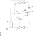
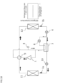
- FIG. 1 is a schematic configuration diagram showing a refrigeration cycle device 100 according to Embodiment 1.
- the refrigeration cycle device 100 includes a main circuit and a bypass circuit, through each of which a non-azeotropic mixed refrigerant is circulated.
- the refrigeration cycle device 100 further includes a controller 20 for controlling operations of a compressor 1, a first heat exchanger 2, a supercooling heat exchanger 3, a first expansion valve 4, a second heat exchanger 5, and a bypass expansion valve 6, etc.
- non-azeotropic mixed refrigerant means a refrigerant which includes, at least in part, any one of the following refrigerants: an olefin refrigerant such as tetrafluoropropene (HFO1234yf) and trifluoroethylene (HFO1123); an ether refrigerant such as dimethyl ether; a hydrocarbon refrigerant such as propane (HC290) and isobutane (HC600a); an ethane refrigerant such as tetrafluoroethane (HFC134a) and pentafluoroethane (HFC125); a methane refrigerant such as difluoromethane (HFC32); and a refrigerant having a lower gas density than difluoromethane.
- an olefin refrigerant such as tetrafluoropropene (HFO1234yf) and trifluoroethylene (HFO1123
- Olefin means that the refrigerant contains a carbon-carbon double bond in its composition.
- “Ether” means that the refrigerant contains an ether bond in its composition.
- “Hydrocarbon” means that the refrigerant contains both carbon and hydrogen in its composition.
- “Ethane” means that the refrigerant contains ethane in its composition, and “methane” means that the refrigerant contains methane in its composition.
- the non-azeotropic mixed refrigerant is simply referred to as refrigerant.
- the main circuit of the refrigeration cycle device 100 includes the compressor 1, the first heat exchanger 2, the supercooling heat exchanger 3, the first expansion valve 4, and the second heat exchanger 5.
- the compressor 1, the first heat exchanger 2, the supercooling heat exchanger 3, the first expansion valve 4, and the second heat exchanger 5, which constitute the main circuit, are each connected by refrigerant piping.
- the flow direction of the refrigerant in the present embodiment (the direction indicated by arrows in FIG. 1 ) is referred to as a first direction.
- the refrigerant inflow side is the side from which the refrigerant comes in
- the refrigerant outflow side is the side to which the refrigerant goes out.
- the compressor 1 sucks in the refrigerant from the refrigerant inflow side to compress it and discharge it from the refrigerant outflow side as a single phase gas at high temperature and pressure.
- the compressor 1 is configured so that its revolving speed can be controlled by, for example, an inverter circuit and the discharge rate of the refrigerant can be adjusted.
- the operation of the compressor 1 is controlled on the basis of a control signal from the controller 20.
- the first heat exchanger 2 functions as a condenser.
- the refrigerant in the gas single phase at high temperature and high pressure due to the compression of the compressor 1 flows from the refrigerant inflow side into the first heat exchanger 2 to be cooled by the heat exchange with a heat source into a liquid state of low temperature and high pressure. Then, the refrigerant in the liquid state is then discharged from the refrigerant outflow side of the first heat exchanger 2.
- the heat sources for the first heat exchanger 2 are air (outdoor air), water, antifreeze, etc.
- the refrigerant flowing through the first heat exchanger 2 exchanges heat with the outdoor air, for example.
- the refrigeration cycle device 100 may include a blower (not illustrated) that blows the outdoor air to the first heat exchanger 2 while the refrigerant circulates within the refrigeration cycle device 100.
- the air flow of the blower should be adjustable.
- the supercooling heat exchanger 3 is a heat exchanger in which the refrigerant flowing through multiple refrigerant circuits inserted in the supercooling heat exchanger 3 exchanges heat with each other.
- the multiple refrigerant circuits are the main circuit and the bypass circuit.
- the supercooling heat exchanger 3 cools pre-decompressed liquid refrigerant flowing through the main circuit by using post-decompressed refrigerant in the gas-liquid two-phase state flowing through the bypass circuit.
- the pre-decompressed refrigerant flowing through the main circuit and the post-decompressed refrigerant flowing through the bypass circuit can exchange heat because their temperatures are different due to the pressure difference.
- the inflow of the refrigerant into the supercooling heat exchanger 3 through the bypass circuit reduces the refrigerant flow rate into the second heat exchanger 5.
- the increase in the enthalpy difference of the refrigerant before and after the second heat exchanger 5 cancels out the reduction of the heat exchange amount due to the decrease in the refrigerant flow rate, so that the heat exchange amount in the second heat exchanger 5 can be maintained.
- the first expansion valve 4 into which the liquid refrigerant cooled to low temperature and high pressure by the first heat exchanger 2 flows, decompresses and expands the refrigerant into a liquid or gas-liquid two-phase state refrigerant of low temperature and low pressure.
- the first expansion valve 4 is a main expansion valve (a main pressure reducing device), which includes a refrigerant flow rate control means such as an electronic expansion valve and a temperature-sensitive expansion valve, and a capillary tube, for example.
- the operation of the first expansion valve 4 is controlled on the basis of a control signal from the controller 20.
- the second heat exchanger 5 functions as an evaporator.
- the second heat exchanger 5 is, for example, a plate fin tube heat exchanger with multiple heat transfer tubes, multiple fins, a refrigerant manifold, and a header. From the refrigerant inflow side, the liquid or gas-liquid two-phase state refrigerant of low temperature and low pressure, decompressed and expanded by the first expansion valve 4, flows into the second heat exchanger 5.
- the refrigerant exchanges heat with a cooling target to absorb heat and cool it.
- the refrigerant evaporates and becomes a low pressure single phase gas while cooling the target.
- the refrigerant in the gas single phase is discharged from the refrigerant outflow side.
- the cooling target is, for example, indoor air. That is, the second heat exchanger 5 exchanges heat between the indoor air and the refrigerant.
- the refrigeration cycle device 100 may include a blower (not illustrated) that blows the indoor air to the second heat exchanger 5 while the refrigerant circulates within the refrigeration cycle device 100.
- the air flow of the blower should be adjustable.
- the second heat exchanger 5 (evaporator) is designed to cause a pressure loss in the refrigerant such that, at a given refrigerant flow rate, the difference between a temperature at the refrigerant inflow side and a saturated gas temperature at the refrigerant outflow side is less than a set temperature difference in the second heat exchanger 5.
- the temperature at the refrigerant inflow side of the evaporator means a temperature at an inlet of the evaporator or a refrigerant temperature at the refrigerant inflow side.
- the pressure loss in the second heat exchanger 5 can be adjusted, for example, by changing the number of refrigerant channels (number of passes) or the refrigerant channel diameter in the second heat exchanger 5.
- the set temperature difference mentioned above is, for example, 2 °C. This temperature setting is based on the known fact that the uneven frost formation is unlikely to occur if the difference between the inflow side and the outflow side temperatures in the second heat exchanger 5 is less than 2 °C.
- the temperature of the refrigerant within the second heat exchanger 5 increases as the refrigerant moves toward the flow direction.
- R407C a mixture of HFC134a, HFC125 and HFC32 refrigerant
- a temperature gradient of more than 6 °C may occur within the second heat exchanger 5.
- the greater the temperature gradient of the circulating refrigerant, for example, 3 °C or greater the more likely the uneven frost formation occurs in the second heat exchanger 5.
- the temperature of the refrigerant also decreases. That is to say, even in the refrigeration cycle device 100 including the non-azeotropic mixed refrigerant, the adjustment of the pressure loss amount of the refrigerant within the second heat exchanger 5 reduces the temperature change of the refrigerant during evaporation, thereby eliminating the temperature difference in the flow direction within the second heat exchanger 5, which in turn enables the suppression of the uneven frost formation in the second heat exchanger 5, i.e., in the evaporator.
- the refrigerant flowing out of the compressor 1 flows into the first heat exchanger 2 (condenser).
- the refrigerant that flows into the first heat exchanger 2 for example, exchanges heat with a medium to be heated such as the air and then condenses.
- the refrigerant then flows from the first heat exchanger 2 into the supercooling heat exchanger 3.
- the refrigerant flowing into the supercooling heat exchanger 3 is cooled by the refrigerant circulating in the bypass circuit.
- the refrigerant flowing from the supercooling heat exchanger 3 is divided into refrigerant flowing through the main circuit and refrigerant flowing through the bypass circuit.
- the refrigerant flowing through the main circuit after the split will be described.
- the refrigerant flows from the supercooling heat exchanger 3 to the first expansion valve 4, where it is decompressed and then flows to the second heat exchanger 5 (evaporator).
- the refrigerant flows into the second heat exchanger 5 and exchanges heat with a medium to be cooled and evaporates.
- the evaporated refrigerant is sucked in by the compressor 1 and compressed.
- the bypass expansion valve 6 is fully closed, the refrigerant will not flow into the bypass circuit.
- the bypass circuit will be described.
- the bypass circuit has an inlet and an outlet and is connected to the main circuit through the inlet and outlet. As shown in FIG. 1 , the inlet is located between the refrigerant outflow side of the first heat exchanger 2 and the refrigerant inflow side of the second heat exchanger 5. The outlet is located between the refrigerant outflow side of the second heat exchanger 5 and the refrigerant inflow side of the compressor 1.
- the bypass circuit includes the bypass expansion valve 6 between its inlet and outlet.
- the bypass expansion valve 6 When the bypass expansion valve 6 is opened, the refrigerant diverted from the main circuit is introduced into the bypass circuit.
- the behavior of the bypass expansion valve 6, i.e., the degree to which the bypass expansion valve 6 is opened, is controlled on the basis of the control signal from the controller 20.
- the bypass expansion valve 6 decompresses and expands the refrigerant to a liquid or gas-liquid two-phase state of low temperature and low pressure.
- the refrigerant piping in the bypass circuit is configured such that the refrigerant circulating in the bypass circuit also circulates to the supercooling heat exchanger 3.
- the refrigerant to be circulated through the bypass circuit flows in from its inlet, is decompressed by the bypass expansion valve 6, and then flows into the supercooling heat exchanger 3.
- the refrigerant exchanges heat with the refrigerant flowing through the main circuit, and then flows out of the supercooling heat exchanger 3.
- the refrigerant flowing out of the outlet of the supercooling heat exchanger 3 in the bypass circuit is mixed with the refrigerant from the main circuit and sucked in by the compressor 1.
- the refrigerant flowing into the bypass expansion valve 6 cools the refrigerant before the diversion, i.e., the refrigerant flowing through the main circuit and evaporates.
- the pressure reduction by the bypass expansion valve 6 makes the refrigerant flowing through the bypass circuit cooler than the high-pressure side refrigerant flowing through the supercooling heat exchanger 3.
- the refrigerant flowing through the bypass circuit can cool the refrigerant flowing through the main circuit via the supercooling heat exchanger 3.
- the circulation of the refrigerant in the bypass circuit reduces the refrigerant flow rate into the second heat exchanger 5, but does not reduce the heat exchange amount in the second heat exchanger 5 due to the decrease in the enthalpy of the refrigerant flowing into the second heat exchanger 5.
- the decrease in the refrigerant flow rate into the second heat exchanger 5 reduces the pressure loss in the second heat exchanger 5.
- An increase in the opening degree of the bypass expansion valve 6 causes an increase in the heat exchange amount in the supercooling heat exchanger 3 and a decrease in the refrigerant flow rate into the second heat exchanger 5. That is, the pressure loss in the second heat exchanger 5 can be adjusted while ensuring the heat exchange amount by controlling the opening degree of the bypass expansion valve 6 by the controller 20.
- the inlet of the bypass circuit should be located between the refrigerant outflow side of the supercooling heat exchanger 3 and the refrigerant inflow side of the first expansion valve 4.
- the refrigerant circulating through the main circuit is in a liquid state when it flows out after the heat exchange between the refrigerants.
- the refrigerant decompressed by the first expansion valve 4 may be in a gas-liquid two-phase state.
- the location of the inlet of the bypass circuit between the refrigerant outflow side of the supercooling heat exchanger 3 and the refrigerant inflow side of the first expansion valve 4 as described above allows the refrigerant to be divided in the liquid state and facilitates the management of the flow rates of the refrigerants circulating separately through the main circuit and the bypass circuit.
- the heat exchange performance of the supercooling heat exchanger 3 can be improved without complex refrigerant piping, because the refrigerants circulating through the main circuit and the refrigerant circulating through the bypass circuit flow in opposite directions within the supercooling heat exchanger 3.
- the controller 20 of the Refrigeration cycle device 100 will be described.
- the controller 20 controls the revolving speed of the compressor 1 and thus adjusts the refrigerant flow rate from the compressor 1.
- the controller 20 controls the first expansion valve 4 and the bypass expansion valve 6 to adjust their respective opening degrees.
- the controller 20 also controls the opening degree of the bypass expansion valve 6 using sensor information obtained from a first sensor 7 and a second sensor, which will be described next.
- the first sensor 7 and the second sensor 8 are included in the refrigeration cycle device 100.
- the first sensor 7, which is a temperature sensor, is located at the refrigerant inflow side of the second heat exchanger 5 to obtain the temperature of the inflowing refrigerant, for example, as shown in FIG. 1 .
- the second sensor 8, which is a pressure sensor, is located between the refrigerant outflow side of the second heat exchanger 5 and the refrigerant inflow side of the compressor 1 to obtain the pressure of the refrigerant in the gas single phase at the refrigerant outflow side of the second heat exchanger 5, for example, as shown in FIG. 1 .
- the controller 20 obtains the pressure of the refrigerant at the refrigerant outflow side of the second heat exchanger 5 from the second sensor 8 and calculates the saturated gas temperature at the refrigerant outflow side of the second heat exchanger 5 on the basis of, for example, the data stored in a memory (not illustrated) included in the controller 20, in which the pressure of the refrigerant and the saturated gas temperature are associated with each other.
- the second sensor 8 measuring the pressure of the refrigerant should preferably be located between the refrigerant outflow side of the second heat exchanger 5 and the bypass circuit. This is because, in the refrigeration cycle device 100 in which the non-azeotropic mixed refrigerant is used, the system for obtaining the pressure of the refrigerant and converting it to a temperature allows accurate measurement of the temperature of a location where the uneven frost formation may occur in the second heat exchanger 5, as described next.
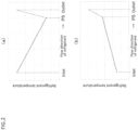
- FIG. 2 is an explanatory diagram showing an example of temperature distribution of refrigerant within the evaporator according to Embodiment 1.
- the vertical axis represents the temperature of the refrigerant in the evaporator and the horizontal axis represents the position of the refrigerant in the flow direction in the evaporator.
- the evaporator inlet is on the left and its outlet is on the right.
- FIGS. 2(a) and 2(b) the evaporator inlet is on the left and its outlet is on the right.
- the solid line indicates that the refrigerant is in the gas-liquid two-phase state
- the point PS indicates that the refrigerant is in the saturated gas state
- the dashed line indicates that the refrigerant is in the gas single phase state.
- the non-azeotropic mixed refrigerant changes its state in the evaporator to the saturated gas state via the gas-liquid two-phase state.
- the heat absorbed from the environment is used to raise the temperature as well as to change the phase. In some cases, this causes the temperature in the evaporator to decrease, as shown by the solid line in FIG. 2(a) . In other cases, it causes the temperature in the evaporator to rise gradually, as shown by the solid line in FIG 2(b) .
- the refrigerant in the gas single phase which has passed through the saturated gas state, immediately increases its temperature because it uses the heat absorbed from the environment only for increasing its temperature as shown by the dashed lines in FIGS. 2(a) and 2(b) .
- directly obtaining the temperature at the refrigerant outflow side of the evaporator as is means obtaining the refrigerant temperature that has already reached a high level. Therefore, it may not be possible to obtain the valid difference between the temperature at the refrigerant inflow side and the temperature at the refrigerant outflow side in the evaporator.
- controller 20 cannot perform a control to suppress the uneven frost formation even though there is a low-temperature location, i.e., a location where the uneven frost formation may occur, within the evaporator, as shown in FIG. 2(a) , for example.
- the saturated gas temperature can be calculated from the pressure of the refrigerant flowing out of the evaporator as measured by the second sensor 8. This gives the temperature at a point where all of the refrigerants included in the non-azeotropic mixed refrigerant have evaporated, i.e., the temperature at the end point PS of the solid line in each of FIGS. 2(a) and 2(b) . This makes it possible to obtain the temperature at the refrigerant outflow side in the evaporator and the exact difference between the temperature at the refrigerant inflow side and the temperature at the refrigerant outflow side in the evaporator, thereby enabling the controller 20 to suppress the uneven frost formation. Next, the control by means of the controller 20 will be described.
- the refrigerant temperature at the refrigerant inflow side of the second heat exchanger 5 is simply referred to as the refrigerant temperature
- the saturated gas temperature at the refrigerant outflow side of the second heat exchanger 5 is simply referred to as the saturated gas temperature.
- the controller 20 controls the opening degree of the bypass expansion valve 6 to adjust the refrigerant flow rate into the second heat exchanger 5 (evaporator). The operation of the controller 20 will be described below, along with examples of the operation state of the refrigeration cycle device 100 according to the present embodiment.
- the operation of the controller 20, to be described next, is performed when the refrigerant temperature or the saturated gas temperature falls below a set temperature to suppress the uneven frost formation at the refrigerant inflow side or the refrigerant outflow side of the evaporator.
- the set temperature above is 2 °C, for example. This setting temperature is based on the knowledge that the uneven frost formation may occur if the refrigerant temperature or the saturated gas temperature of the second heat exchanger 5 falls below 2 °C.
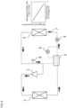
- FIG. 3 is an explanatory diagram showing the first example of the operation state of the refrigeration cycle device 100 according to Embodiment 1.
- the graph on the right side is a graph that schematically shows the temperature of the refrigerant flowing in the evaporator.
- the vertical axis of the graph represents the refrigerant temperature
- the horizontal axis represents the position of the refrigerant in the flow direction in the evaporator. That is, the refrigerant inflow side of the evaporator is the left side of the graph, and the refrigerant outflow side of the evaporator is the right side of the graph.
- FIGS. 4 through 8 and FIGS. 13 through 18 The same is true for the graphs shown in FIGS. 4 through 8 and FIGS. 13 through 18 below.
- the refrigerant flow rate from the compressor 1 is Qa
- the second heat exchanger 5 is designed such that the difference between the temperature at the refrigerant inflow side and the saturated gas temperature is less than 2 °C when the refrigerant flow rate into the second heat exchanger 5 is Qa.
- the bypass expansion valve 6 is fully closed and the refrigerant flow rate into the second heat exchanger 5 is Qa, so that the difference between the temperature at the refrigerant inflow side and the saturated gas temperature in the second heat exchanger 5 is less than 2 °C. Therefore, in the first example, the uneven frost formation on the surface of the second heat exchanger 5, i.e., the evaporator, is suppressed.
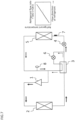
- FIG. 4 is an explanatory diagram showing the second example of the operation state of the refrigeration cycle device 100 according to Embodiment 1.
- FIG. 4 shows an example in which the refrigerant flow rate from the compressor 1 is Qa1, which is greater than Qa, and the bypass expansion valve 6 is fully closed.
- the refrigerant flow rate into the second heat exchanger 5 is also Qa1, the pressure loss of the refrigerant within the second heat exchanger 5 is larger compared to when the refrigerant flow rate into the second heat exchanger 5 is Qa.
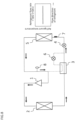
- FIG. 5 is an explanatory diagram showing the third example of the operation state of the refrigeration cycle device 100 according to Embodiment 1.
- FIG. 5 shows an example in which the bypass expansion valve 6 is in an open state and the refrigerant flow rate from the compressor 1 is Qa1, which is the same as that in the second example.
- the controller 20 calculates the refrigerant temperature and the saturated gas temperature of the second heat exchanger 5 using the sensor information obtained from the first sensor 7 and the second sensor 8, respectively.
- the controller 20 compares the refrigerant temperature and the saturated gas temperature when the difference between the refrigerant temperature and the saturated gas temperature in the second heat exchanger 5 is equal to or greater than the set temperature difference. When the saturated gas temperature is lower than the refrigerant temperature, the controller 20 opens the bypass expansion valve 6 to reduce the refrigerant flow rate through the main circuit.
- the reduction of the refrigerant flow rate through the main circuit reduces the refrigerant flow rate into the second heat exchanger 5, so that the pressure loss of the refrigerant in the second heat exchanger 5 is reduced. Therefore, as shown in FIG. 5 , the temperature drop at the refrigerant outflow side of the second heat exchanger 5 can be suppressed, and thus the uneven frost formation at the refrigerant outflow side in the second heat exchanger 5, or the evaporator, can be suppressed.
- the second heat exchanger 5 is designed such that, with no refrigerant flowing into the bypass circuit, the difference between the temperature at the refrigerant inflow side and the saturated gas temperature at the refrigerant outflow side in the second heat exchanger 5 is less than the set temperature difference.
- the second heat exchanger 5 it is also possible to design the second heat exchanger 5 such that, with the refrigerant being divided and flowing into both the bypass circuit and the main circuit, the difference between the temperature at the refrigerant inflow side and the saturated gas temperature at the refrigerant outflow side in the second heat exchanger 5 is less than the set temperature difference.
- FIG. 6 is an explanatory diagram showing the fourth example of the operation state of the refrigeration cycle device 100 according to Embodiment 1.
- the second heat exchanger 5 is designed such that, when the refrigerant flow rate from the compressor 1 is Qb1 and the refrigerant flow rate into the second heat exchanger 5 is Qb, which is smaller than Qb1, the difference between the temperature at the refrigerant inflow side and the saturated gas temperature at the refrigerant outflow side is less than 2 °C.
- the temperature difference between the refrigerant inflow side and the refrigerant outflow side in the second heat exchanger 5 is less than 2 °C. Therefore, in the fourth example, the uneven frost formation on the surface of the second heat exchanger 5, or the evaporator, is suppressed.
- the refrigerant flow rate into the bypass circuit is Qb1-Qb.
- FIG. 7 is an explanatory diagram showing the fifth example of the operation state of the refrigeration cycle device 100 according to Embodiment 1.
- FIG. 7 shows an example, in which the refrigerant flow rate from the compressor 1 is Qb2, which is smaller than Qb1, and the bypass expansion valve 6 is in an open state.
- the refrigerant flow rate into the second heat exchanger 5 is a value less than Qb, the pressure loss of the refrigerant within the second heat exchanger 5 is lower compared to when the refrigerant flow rate into the second heat exchanger 5 is Qb.
- FIG. 8 is an explanatory diagram showing the sixth example of the operation state of the refrigeration cycle device 100 according to Embodiment 1.
- FIG. 8 shows an example, in which the bypass expansion valve 6 is fully closed and the refrigerant flow rate from the compressor 1 is Qb2, which is the same as that in the fifth example.
- the controller 20 calculates the refrigerant temperature and the saturated gas temperature of the second heat exchanger 5 using the sensor information obtained from the first sensor 7 and the second sensor 8, respectively.
- the controller 20 compares the refrigerant temperature and the saturated gas temperature when the difference between the refrigerant temperature and the saturated gas temperature in the second heat exchanger 5 is equal to or greater than the set temperature difference. When the refrigerant temperature is lower than the saturated gas temperature, the controller 20 closes the bypass expansion valve 6 to increase the refrigerant flow rate through the main circuit.
- the increase of the refrigerant flow rate through the main circuit increases the refrigerant flow rate into the second heat exchanger 5, so that the pressure loss of the refrigerant in the second heat exchanger 5 is increased. As shown in FIG. 8 , this suppresses the temperature drop at the refrigerant inflow side in the second heat exchanger 5 and thus suppresses the uneven frost formation at the refrigerant inflow side in the second heat exchanger 5, i.e., the evaporator.
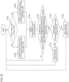
- FIG. 9 is a flowchart showing an operation example of the controller 20 of the refrigeration cycle device 100 according to Embodiment 1. Although the flowchart in FIG. 9 does not include a process for terminating the operation of the controller 20, the controll er 20 terminates its operation, for example, when it receives a command to terminate its operation from a remote controller (not shown) or the like.
- the controller 20 obtains the sensor information from the first sensor 7 (ST101).
- the controller 20 obtains the sensor information from the second sensor 8 (ST102).
- the sensor information obtained from the first sensor 7 and the second sensor 8 is the temperature of the refrigerant and the pressure of the refrigerant, respectively.
- the controller 20 compares the refrigerant temperature and the saturated gas temperature using the obtained sensor information to determine whether the difference between the refrigerant temperature and the saturated gas temperature is greater than the set temperature difference (ST103). If the difference between the refrigerant temperature and the saturated gas temperature is less than the set temperature difference (ST103; NO), the operation of the controller 20 proceeds to the processing of ST101.
- the controller 20 compares the refrigerant temperature and the saturated gas temperature and determines which of the refrigerant temperature and the saturated gas temperature is lower (ST104).
- the controller 20 opens the bypass expansion valve 6 to reduce the refrigerant flow rate through the main circuit. If the saturated gas temperature is lower than the refrigerant temperature, the uneven frost formation may occur at the refrigerant outflow side of the second heat exchanger 5. As shown in the third example of the operation state of the refrigeration cycle device 100, opening the bypass expansion valve 6 reduces the refrigerant flow rate into the second heat exchanger 5, which reduces the pressure loss of the refrigerant within the second heat exchanger 5.
- the operation of the controller 20 proceeds to the processing of ST101.
- the controller 20 closes the bypass expansion valve 6 to increase the refrigerant flow rate through the main circuit. If the refrigerant temperature is lower than the saturated gas temperature, the uneven frost formation may occur at the refrigerant outflow side of the second heat exchanger 5. As shown in the sixth example of the operation state of the refrigeration cycle device 100, closing the bypass expansion valve 6 increases the refrigerant flow rate into the second heat exchanger 5, which increases the pressure loss of the refrigerant within the second heat exchanger 5.
- the operation of the controller 20 proceeds to the processing of ST101.
- the open/close control of the bypass expansion valve 6 by the controller 20 described above it is possible to adjust the amount by which the bypass expansion valve 6 is opened.
- the adjustment of the refrigerant flow rates through the main circuit and the bypass circuit enabled by the control of the opening degree of the bypass expansion valve 6, can offset the temperature increase due to the temperature gradient of the refrigerant and the temperature drop due to the pressure loss in the evaporation process of the refrigerant.
- the refrigerant flow rate into the evaporator can be changed to ensure a certain amount of heat exchange in the evaporator.
- the refrigeration cycle device 100 with a main circuit in which a compressor 1, a condenser, a supercooling heat exchanger 3, a main expansion valve, and an evaporator are connected by refrigerant piping to circulate a non-azeotropic mixed refrigerant, and a bypass circuit branched from between the condenser and the evaporator to be connected to a refrigerant inflow side of the compressor 1, the bypass circuit including a bypass expansion valve 6 to introduce the non-azeotropic mixed refrigerant from the main circuit, the supercooling heat exchanger 3 exchanging heat between the non-azeotropic mixed refrigerant flowing through the main circuit and the non-azeotropic mixed refrigerant flowing through the bypass circuit, the refrigeration cycle device 100 includes: a controller 20 to control an opening degree of the bypass expansion valve 6; a first sensor 7 to detect a temperature at the refrigerant inflow side of the evaporator; and a second sensor 8 to detect a pressure of the non-azeotropic
- the inlet of the bypass circuit is located between the refrigerant outflow side of the supercooling heat exchanger 3 and the refrigerant inflow side of the first expansion valve 4, the requirement for the location of the inlet of the bypass circuit is to be between the refrigerant outflow side of the first heat exchanger 2 and the refrigerant inflow side of the second heat exchanger 5.
- the inlet of the bypass circuit may be located between the refrigerant outflow side of the first expansion valve 4 and the refrigerant inflow side of the second heat exchanger 5.
- FIG. 10 is a schematic configuration diagram showing the refrigeration cycle device 100 according to Embodiment 1.
- the heat exchange performance of the supercooling heat exchanger 3 can be improved without complex refrigerant piping, because the refrigerants circulating through the main circuit and the refrigerant circulating through the bypass circuit flow in opposite directions within the supercooling heat exchanger 3.
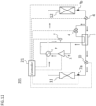
- FIGS. 11 and 12 are each a configuration diagram schematically showing a refrigeration cycle device 101 according to Embodiment 2.
- the refrigeration cycle device 101 according to the present embodiment includes the main circuit through which the refrigerant circulates, the bypass expansion valve 6, the bypass circuit through which the refrigerant circulates, and a controller 21 that controls the opening degree of the bypass expansion valve 6.
- the present embodiment differs from Embodiment 1 in that the main circuit includes a four-way valve 9, and a first heat exchanger 11 and a second heat exchanger 12 function as both an evaporator and a condenser.
- the same components as those in Embodiment 1 are marked with the same symbols and their descriptions are omitted.
- the four-way valve 9 is located on the refrigerant outflow side of the compressor 1.
- the four-way valve 9 switches the refrigerant flow direction between the first direction (direction indicated by the arrows in FIG. 11 ) and the second direction (direction indicated by the arrows in FIG. 12 ) in the main circuit.
- the operation of the four-way valve 9 is controlled by the controller 21.
- the state of the four-way valve 9 that causes the refrigerant flow direction to be the first direction is called a first state (the state shown in FIG. 11 ), and the state of the four-way valve 9 that causes the refrigerant flow direction to be the second direction is called a second state (the state shown in FIG. 12 ).
- the refrigerant flow direction is the first direction as in Embodiment 1.
- the refrigerant flow direction is not the first direction, but the second direction. That is, when the four-way valve 9 is in the first state, the first heat exchanger 11 serves as a condenser and the second heat exchanger 12 serves as an evaporator, as in Embodiment 1. On the other hand, when the four-way valve 9 is in the second state, the first heat exchanger 11 serves as an evaporator and the second heat exchanger 12 serves as a condenser.
- the first heat exchanger 11 is designed such that, when it serves as an evaporator and the refrigerant flows at a specific flow rate, the difference between the temperature at the refrigerant inflow side and the saturated gas temperature at the refrigerant outflow side in the first heat exchanger 11 is controlled to be less than the set temperature difference, thereby causing a pressure loss in the refrigerant.
- the pressure loss in the first heat exchanger 11 can be adjusted, for example, by changing the number of refrigerant channels (number of passes) or the refrigerant channel diameter in the first heat exchanger 11.
- the set temperature difference is 2 °C, for example.
- the second heat exchanger 12 is also designed such that, when it serves as an evaporator and the refrigerant flows at a specific flow rate, the difference between the temperature at the refrigerant inflow side and the saturated gas temperature at the refrigerant outflow side in the second heat exchanger 12 is controlled to be less than the set temperature difference, thereby causing a pressure loss in the refrigerant.
- the pressure loss in the second heat exchanger 12 can be adjusted, for example, by changing the number of refrigerant channels (number of passes) or the refrigerant channel diameter in the second heat exchanger 12.
- the set temperature difference is 2 °C, for example.
- the first heat exchanger 11 and the second heat exchanger 12 may be given the same flow rate or different flow rates from each other.
- the main circuit in the refrigeration cycle device 101 includes a second expansion valve.
- the second expansion valve is located between the first heat exchanger 11 and the supercooling heat exchanger 3.
- the second expansion valve sucks in the liquid refrigerant of low temperature and high pressure cooled by the condenser and decompresses and expands it into the liquid or gas-liquid two-phase state of low temperature and low pressure.
- the second expansion valve is a main expansion valve (a main pressure reducing device), which includes a refrigerant flow rate control means such as an electronic expansion valve and a temperature-sensitive expansion valve, and a capillary tube, for example.
- the refrigerant, decompressed and expanded by the second expansion valve flows into the first heat exchanger 11.
- the refrigerant, decompressed and expanded by the first expansion valve 4 flows into the second heat exchanger 12.
- the refrigeration cycle device 101 includes a plurality of the first sensors.
- the plurality of first sensors is located such that they can obtain the temperatures of the refrigerants flowing into the first heat exchanger 11 and the second heat exchanger 12.
- one of the plurality of first sensors is located so as to obtain the temperature at the refrigerant inflow side of the first heat exchanger 11 serving as an evaporator, and another is located so as to obtain the temperature at the refrigerant inflow side of the second heat exchanger 12 serving as an evaporator.
- first sensors there are two of the first sensors.
- One of them, or a first sensor 7a is located between the refrigerant inflow side of the first heat exchanger 11 and the refrigerant outflow side of the second expansion valve 10 when the first heat exchanger 11 serves as an evaporator, in other words, when the refrigerant flow direction is the second direction.
- the other one, or a first sensor 7b is located between the refrigerant inflow side of the second heat exchanger 12 and the refrigerant outflow side of the first expansion valve 4 when the second heat exchanger 12 serves as an evaporator, in other words, when the refrigerant flow direction is the first direction.
- the refrigerant flows from the compressor 1 through the four-way valve 9 into the first heat exchanger 11 (condenser).
- the refrigerant exchanges heat with the medium to be heated and condenses.
- the refrigerant flows from the first heat exchanger 11 through the second expansion valve into the supercooling heat exchanger 3 to be cooled by the refrigerant flowing through the bypass circuit.
- the refrigerant flows out of the supercooling heat exchanger 3 to be divided into the refrigerant flowing through the main circuit and the refrigerant flowing through the bypass circuit.
- the refrigerant flowing through the main circuit after the flow division will be described.
- the refrigerant flows from the supercooling heat exchanger 3 into the first expansion valve 4, where it is decompressed, and then into the second heat exchanger 12 (evaporator).
- the second heat exchanger 12 the refrigerant exchanges heat with the medium to be cooled and evaporates.
- the evaporated refrigerant is sucked into the compressor 1 through the four-way valve 9.
- the refrigerant flowing into the bypass expansion valve 6 is decompressed there, flows into the supercooling heat exchanger 3, cools the refrigerant before the flow division, evaporates, merges with the refrigerant from the main circuit, and is sucked into the compressor 1.
- the bypass expansion valve 6 is fully closed, the refrigerant does not flow into the bypass circuit.
- the flow of the refrigerant in FIG. 12 is different from the flow of the refrigerant in FIG. 11 .
- the refrigerant flows from the compressor 1 through the four-way valve 9 into the second heat exchanger 12 (condenser).
- the refrigerant exchanges heat with the medium to be heated and condenses.
- the refrigerant flows from the second heat exchanger 12 to be divided into the refrigerant flowing through the main circuit and the refrigerant flowing through the bypass circuit. The refrigerant flowing through the main circuit after the flow division will be described.
- the refrigerant flows through the first expansion valve 4 into the supercooling heat exchanger 3 to be cooled there by the refrigerant flowing through the bypass circuit. Then, the refrigerant flows from the supercooling heat exchanger 3 through the second expansion valve 10 where it is decompressed and enters the first heat exchanger 11 (evaporator). In the first heat exchanger 11, the refrigerant exchanges heat with the medium to be cooled and evaporates. The evaporated refrigerant merges with the refrigerant flowing through the main circuit and is sucked into the compressor 1. When the bypass expansion valve 6 is fully closed, the refrigerant does not flow into the bypass circuit.
- the pressure reduction by the bypass expansion valve 6 makes the refrigerant flowing through the bypass circuit cooler than the high-pressure side refrigerant flowing through the supercooling heat exchanger 3.
- the refrigerant flowing through the bypass circuit can cool the refrigerant flowing through the main circuit via the supercooling heat exchanger 3.
- the circulation of the refrigerant in the bypass circuit reduces the refrigerant flow rate into the evaporator, but does not reduce the heat exchange amount in the evaporator due to the decrease in the enthalpy of the refrigerant flowing into the evaporator.
- the decrease in the refrigerant flow rate into the evaporator reduces the pressure loss in the evaporator.
- An increase in the opening degree of the bypass expansion valve 6 causes an increase in the heat exchange amount in the supercooling heat exchanger 3 and a decrease in the refrigerant flow rate into the evaporator. That is, the pressure loss in the evaporator can be adjusted by controlling the opening degree of the bypass expansion valve 6.
- the controller 21 calculates the refrigerant temperature and the saturated gas temperature by using the sensor information obtained from the first sensors 7a and 7b and the second sensor 8, respectively, controls the opening degree of the bypass expansion valve 6, and thereby adjusts the refrigerant flow rates through the main circuit and the bypass circuit.
- the operation of the controller 21 will be described below, along with examples of the operation state of the refrigeration cycle device 101 according to the present embodiment.
- the operation of the controller 21 described below is performed when the refrigerant temperature at the refrigerant inflow side or the saturated gas temperature at the refrigerant outflow side of the evaporator falls below the set temperature.
- the above-mentioned set the temperature is, for example, 2 °C.
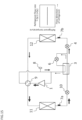
- FIG. 13 is an explanatory diagram showing the first example of the operation state of the refrigeration cycle device 101 according to Embodiment 2.
- the first example is an example of the operation state of the refrigeration cycle device 101 in which the four-way valve 9 is in the first state.
- the second heat exchanger 12 is designed such that the difference between the temperature at the refrigerant inflow side and the saturated gas temperature at the refrigerant outflow side is less than 2 °C when the refrigerant flow rate from the compressor 1 is Qc and the refrigerant flow rate into the second heat exchanger 12 is Qc.
- the bypass expansion valve 6 is fully closed, and the refrigerant flow rate into the second heat exchanger 12 is Qc, so that the difference between the temperature at the refrigerant inflow side and the saturated gas temperature of the second heat exchanger 12 is less than 2 °C. In the first example, this suppresses the uneven frost formation on the surface of the second heat exchanger 12.
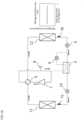
- FIG. 14 is an explanatory diagram showing the second example of the operation state of the refrigeration cycle device 101 according to Embodiment 2.
- the second example is an example of the operation state of the refrigeration cycle device 101 in which the four-way valve 9 is in the first state.
- FIG. 14 shows an example, in which the refrigerant flow rate from the compressor 1 is Qc1, which is greater than Qc, and the bypass expansion valve 6 is fully closed.
- the pressure loss of the refrigerant within the second heat exchanger 12 is higher compared to when the refrigerant flow rate into the second heat exchanger 12 is Qc.
- This causes the saturated gas temperature at the refrigerant outflow side to be lower than the temperature at the refrigerant inflow side in the second heat exchanger 12, so that the uneven frost formation may occur at the refrigerant outflow side in the second heat exchanger 12.
- the uneven frost formation on the second heat exchanger 12 is suppressed by opening the bypass expansion valve 6 as shown in the third example of the operation state of the refrigeration cycle device 101 described below.
- FIG. 15 is an explanatory diagram showing the third example of the operation state of the refrigeration cycle device 101 according to Embodiment 2.
- FIG. 15 shows an example, in which the bypass expansion valve 6 is in an open state and the refrigerant flow rate from the compressor 1 is Qc1, which is the same as in the second example.
- the controller 21 calculates the refrigerant temperature and the saturated gas temperature of the second heat exchanger 12 using the sensor information obtained from the first sensor 7b on the side of the second heat exchanger 12 and the second sensor 8, respectively.
- the controller 21 compares the refrigerant temperature and the saturated gas temperature when the difference between the refrigerant temperature and the saturated gas temperature in the second heat exchanger 12 is equal to or greater than the set temperature difference. When the saturated gas temperature is lower than the refrigerant temperature, the controller 21 opens the bypass expansion valve 6 to reduce the refrigerant flow rate through the main circuit.
- the reduction of the refrigerant flow rate through the main circuit reduces the refrigerant flow rate into the second heat exchanger 12, so that the pressure loss of the refrigerant in the second heat exchanger 12 is reduced. Therefore, the temperature drop at the refrigerant outflow side of the second heat exchanger 12 can be suppressed, and thus the uneven frost formation at the refrigerant outflow side of the second heat exchanger 12, or the evaporator, can be suppressed.
- the four-way valve 9 is in the second state, the uneven frost formation on the evaporator can be suppressed by controlling the opening degree of the bypass expansion valve 6 as in the case when the four-way valve 9 is in the first state.
- the refrigerant temperature at the refrigerant inflow side of the first heat exchanger 11 is simply referred to as the refrigerant temperature
- the saturated gas temperature at the refrigerant outflow side of the second heat exchanger 12 is simply referred to as the saturated gas temperature.
- FIG. 16 is an explanatory diagram showing the fourth example of the operation state of the refrigeration cycle device 101 according to Embodiment 2.
- the fourth example is an example of the operation state of the refrigeration cycle device 101 in which the four-way valve 9 is in the second state.
- the first heat exchanger 11 is designed such that the difference between the temperature at the refrigerant inflow side and the saturated gas temperature is less than 2 °C when the refrigerant flow rate from the compressor 1 is Qd and the refrigerant flow rate into the first heat exchanger 11 is Qd.
- the bypass expansion valve 6 is fully closed, and the refrigerant flow rate into the first heat exchanger 11 is Qd, so that the difference between the temperature at the refrigerant inflow side and the saturated gas temperature of the first heat exchanger 11 is less than 2 °C. In the fourth example, this suppresses the uneven frost formation on the surface of the first heat exchanger 11.
- FIG. 17 is an explanatory diagram showing the fifth example of the operation state of the refrigeration cycle device 101 according to Embodiment 2.
- the fifth example is an example of the operation state of the refrigeration cycle device 101 in which the four-way valve 9 is in the second state.
- FIG. 17 shows an example, in which the refrigerant flow rate from the compressor 1 is Qd1, which is greater than Qd, and the bypass expansion valve 6 is fully closed. In this case, since the refrigerant flow rate into the first heat exchanger 11 is Qd1, the pressure loss of the refrigerant within the first heat exchanger 11 is higher compared to when the refrigerant flow rate into the first heat exchanger 11 is Qd.
- FIG. 18 is an explanatory diagram showing the sixth example of the operation state of the refrigeration cycle device 101 according to Embodiment 2.
- FIG. 18 shows an example, in which the bypass expansion valve 6 is in an open state and the refrigerant flow rate from the compressor 1 is Qd1, which is the same as in the fifth example.
- the controller 21 calculates the refrigerant temperature and the saturated gas temperature of the first heat exchanger 11 using the sensor information obtained from the first sensor 7a on the side of the first heat exchanger 11 and the second sensor 8, respectively.
- the controller 21 compares the refrigerant temperature and the saturated gas temperature when the difference between the refrigerant temperature and the saturated gas temperature in the first heat exchanger 11 is equal to or greater than the set temperature difference.
- the controller 21 opens the bypass expansion valve 6 to reduce the refrigerant flow rate through the main circuit.
- the reduction of the refrigerant flow rate through the main circuit reduces the refrigerant flow rate into the first heat exchanger 11, so that the pressure loss of the refrigerant in the first heat exchanger 11 is reduced. Therefore, the temperature drop at the refrigerant outflow side of the first heat exchanger 11 can be suppressed, and thus the uneven frost formation at the refrigerant outflow side of the first heat exchanger 11, or the evaporator, can be suppressed.
- FIG. 19 is a flowchart showing an example of the operation of the controller 21 of the refrigeration cycle device 101 according to Embodiment 2.
- the steps identical to those described in Embodiment 1 are assigned the same symbols as those in FIG. 9 , and their descriptions are omitted or simplified.
- the flowchart in FIG. 19 does not include a process for terminating the operation of the controller 21, the controller 21 terminates its operation, for example, when it receives a command to terminate its operation from a remote controller or the like.
- the controller 21 obtains information from the four-way valve 9 as to whether the four-way valve 9 is in the first state or in the second state (ST201). If the state of the four-way valve 9 is the first state (ST201; YES), the controller 21 obtains the sensor information from the first sensor 7b on the side of the second heat exchanger 12. If the state of the four-way valve 9 is not the first state, i.e., the second state (ST201; NO), the controller 21 obtains the sensor information from the first sensor 7a on the side of the first heat exchanger 11.
- the sensor information that the controller 21 obtains from the first sensors 7a and 7b is the temperatures of the refrigerants flowing into the first heat exchanger 11 and the second heat exchanger 12, respectively.
- the controller 21 obtains the sensor information indicating the pressure of the refrigerant from the second sensor 8 (ST102). Next, the controller 21 compares the refrigerant temperature and the saturated gas temperature using the obtained sensor information to determine whether the difference between the refrigerant temperature and the saturated gas temperature is greater than or equal to the set temperature difference (ST103). If the difference between the refrigerant temperature and the saturated gas temperature is less than the set temperature difference (ST103; NO), the operation of the controller 21 proceeds to the processing of ST201.
- the controller 21 compares the refrigerant temperature and the saturated gas temperature to determine which of the refrigerant temperature and the saturated gas temperature is lower (ST104).
- the controller 21 opens the bypass expansion valve 6 to reduce the refrigerant flow rate through the main circuit. Opening the bypass expansion valve 6 reduces the refrigerant flow rate into the evaporator (the first heat exchanger 11 or the second heat exchanger 12), which reduces the pressure loss of the refrigerant within the evaporator. Therefore, the temperature drop at the refrigerant outflow side of the evaporator can be suppressed, and thus the uneven frost formation at the refrigerant outflow side of the evaporator can be suppressed. Then, the operation of the controller 21 proceeds to the processing of ST201.
- the controller 21 closes the bypass expansion valve 6 and increases the refrigerant flow rate through the main circuit. Closing the bypass expansion valve 6 increases the refrigerant flow rate into the evaporator (the first heat exchanger 11 or the second heat exchanger 12), which increases the pressure loss of the refrigerant within the evaporator.
- the operation of the controller 21 proceeds to the processing of ST201.
- the open/close control of the bypass expansion valve 6 by the controller 21 described above it is possible to adjust the amount by which the bypass expansion valve 6 is opened.
- the adjustment of the refrigerant flow rates through the main circuit and the bypass circuit enabled by the control of the opening degree of the bypass expansion valve 6, can offset the temperature increase due to the temperature gradient of the refrigerant and the temperature drop due to the pressure loss in the evaporation process of the refrigerant.
- the refrigerant flow rate into the evaporator can be changed to ensure a certain amount of heat exchange in the evaporator.
- bypass circuit is branched from between the supercooling heat exchanger 3 and the first expansion valve 4 when the four-way valve 9 is in the first state, but the bypass circuit may be branched from anywhere between the supercooling heat exchanger 3 and the second heat exchanger 12 when the four-way valve 9 is in the first state.
- the first sensor 7 obtains the temperature of the refrigerant flowing into the evaporator, but this example is not limiting.
- the first sensor 7 may be provided to the inlet of the evaporator to obtain the temperature there as long as the sensor can obtain the temperature at the refrigerant inflow side of the evaporator.
Landscapes
- Engineering & Computer Science (AREA)
- Physics & Mathematics (AREA)
- Mechanical Engineering (AREA)
- Thermal Sciences (AREA)
- General Engineering & Computer Science (AREA)
- Compression-Type Refrigeration Machines With Reversible Cycles (AREA)
- Air Conditioning Control Device (AREA)
Abstract
Description
- The present invention relates to a refrigeration cycle device.
- In recent years, non-azeotropic mixed refrigerants, which are mixtures of several refrigerants with different boiling points, have attracted attention as refrigerants with low global warming coefficients, and the introduction of such non-azeotropic mixed refrigerants into refrigeration cycle devices is being considered to reduce environmental impact.
- The conventional refrigeration cycle device having a main circuit and a bypass circuit detects the inlet and outlet temperatures of the evaporator where refrigerant flows through the main circuit and adjusts the refrigerant flow rate through the bypass circuit so that the temperature difference between the inlet and outlet of the evaporator is such that the heat exchange performance is improved. (See, for example, Patent Document 1).
-
Patent Document 1 Japanese Unexamined Patent Application Publication
JP 2004- 44 883 A - However, since the use of non-azeotropic mixed refrigerant creates a temperature difference in a flow direction of the refrigerant within the evaporator, a low evaporator temperature may result in uneven frost formation on an evaporator surface. Since the above patent document does not address these uneven frost issues, the uneven frost formation on the evaporator surface cannot be adequately suppressed.
- The purpose of the present invention is to solve the above problems and to provide a refrigeration cycle device that can suppress the uneven frost formation on the evaporator and prevent the heat exchange performance from deteriorating.
- The refrigeration cycle device, according to the present invention, with a main circuit in which a compressor, a condenser, a supercooling heat exchanger, a main expansion valve, and an evaporator are connected by refrigerant piping to circulate a non-azeotropic mixed refrigerant, and a bypass circuit branched from between the condenser and the evaporator to be connected to a refrigerant inflow side of the compressor, the bypass circuit including a bypass expansion valve to introduce the non-azeotropic mixed refrigerant from the main circuit, the supercooling heat exchanger exchanging heat between the non-azeotropic mixed refrigerant flowing through the main circuit and the non-azeotropic mixed refrigerant flowing through the bypass circuit, the refrigeration cycle device includes: a controller to control an opening degree of the bypass expansion valve; a first sensor to detect a temperature at the refrigerant inflow side of the evaporator; and a second sensor to detect a pressure of the non-azeotropic mixed refrigerant flowing from the evaporator, wherein the controller controls the opening degree of the bypass expansion valve using the temperature at the refrigerant inflow side of the evaporator detected by the first sensor and a saturated gas temperature of the non-azeotropic mixed refrigerant calculated from the pressure detected by the second sensor and adjusts a flow rate of the non-azeotropic mixed refrigerant flowing into the evaporator.
- According to the present invention, the temperature difference in the flow direction within the evaporator can be eliminated and thus the uneven frost formation on the evaporator is suppressed, so that the heat exchange performance is prevented from deteriorating.
-
- FIG. 1
- is a schematic configuration diagram showing a refrigeration cycle device according to
Embodiment 1. - FIG. 2
- is an explanatory diagram showing an example of temperature distribution of refrigerant within an evaporator according to
Embodiment 1. - FIG. 3
- is an explanatory diagram showing the first example of an operation state of the refrigeration cycle device according to
Embodiment 1. - FIG. 4
- is an explanatory diagram showing the second example of the operation state of the refrigeration cycle device according to
Embodiment 1. - FIG. 5
- is an explanatory diagram showing the third example of the operation state of the refrigeration cycle device according to
Embodiment 1. - FIG. 6
- is an explanatory diagram showing the fourth example of the operation state of the refrigeration cycle device according to
Embodiment 1. - FIG. 7
- is an explanatory diagram showing the fifth example of the operation state of the refrigeration cycle device according to
Embodiment 1. - FIG. 8
- is an explanatory diagram showing the sixth example of the operation state of the refrigeration cycle device according to
Embodiment 1. - FIG. 9
- is a flowchart showing an example of an operation of a controller of the refrigeration cycle device according to
Embodiment 1. - FIG. 10
- is a schematic configuration diagram showing the refrigeration cycle device according to
Embodiment 1. - FIG. 11
- is a schematic configuration diagram showing a refrigeration cycle device according to
Embodiment 2. - FIG. 12
- is a schematic configuration diagram showing the refrigeration cycle device according to
Embodiment 2. - FIG. 13
- is an explanatory diagram showing the first example of the operation state of the refrigeration cycle device according to
Embodiment 2. - FIG. 14
- is an explanatory diagram showing the second example of the operation state of the refrigeration cycle device according to
Embodiment 2. - FIG. 15
- is an explanatory diagram showing the third example of the operation state of the refrigeration cycle device according to
Embodiment 2. - FIG. 16
- is an explanatory diagram showing the fourth example of the operation state of the refrigeration cycle device according to
Embodiment 2. - FIG. 17
- is an explanatory diagram showing the fifth example of the operation state of the refrigeration cycle device according to
Embodiment 2. - FIG. 18
- is an explanatory diagram showing the sixth example of the operation state of the refrigeration cycle device according to
Embodiment 2. - FIG. 19
- is a flowchart showing an example of an operation of a controller of the refrigeration cycle device according to
Embodiment 2. - The embodiments will be described below with reference to the figures. Note that the dimensions of each configuration shown in the figures may differ from the actual ones. The following description is illustrative, and the forms described in the specification are not limiting.
-
FIG. 1 is a schematic configuration diagram showing arefrigeration cycle device 100 according toEmbodiment 1. Therefrigeration cycle device 100 includes a main circuit and a bypass circuit, through each of which a non-azeotropic mixed refrigerant is circulated. Therefrigeration cycle device 100 further includes acontroller 20 for controlling operations of acompressor 1, afirst heat exchanger 2, asupercooling heat exchanger 3, afirst expansion valve 4, asecond heat exchanger 5, and abypass expansion valve 6, etc. - As used herein, the term non-azeotropic mixed refrigerant means a refrigerant which includes, at least in part, any one of the following refrigerants: an olefin refrigerant such as tetrafluoropropene (HFO1234yf) and trifluoroethylene (HFO1123); an ether refrigerant such as dimethyl ether; a hydrocarbon refrigerant such as propane (HC290) and isobutane (HC600a); an ethane refrigerant such as tetrafluoroethane (HFC134a) and pentafluoroethane (HFC125); a methane refrigerant such as difluoromethane (HFC32); and a refrigerant having a lower gas density than difluoromethane.
- "Olefin" means that the refrigerant contains a carbon-carbon double bond in its composition. "Ether" means that the refrigerant contains an ether bond in its composition. "Hydrocarbon" means that the refrigerant contains both carbon and hydrogen in its composition. "Ethane" means that the refrigerant contains ethane in its composition, and "methane" means that the refrigerant contains methane in its composition. In the following description, the non-azeotropic mixed refrigerant is simply referred to as refrigerant.
- The main circuit of the
refrigeration cycle device 100 includes thecompressor 1, thefirst heat exchanger 2, the supercoolingheat exchanger 3, thefirst expansion valve 4, and thesecond heat exchanger 5. Thecompressor 1, thefirst heat exchanger 2, the supercoolingheat exchanger 3, thefirst expansion valve 4, and thesecond heat exchanger 5, which constitute the main circuit, are each connected by refrigerant piping. In the following description, the flow direction of the refrigerant in the present embodiment (the direction indicated by arrows inFIG. 1 ) is referred to as a first direction. In the main circuit and the bypass circuit according to the present embodiment, when the refrigerant is flowing in the first direction, the refrigerant inflow side is the side from which the refrigerant comes in, and the refrigerant outflow side is the side to which the refrigerant goes out. - Next, each of the components of the main circuit will be described. The
compressor 1 sucks in the refrigerant from the refrigerant inflow side to compress it and discharge it from the refrigerant outflow side as a single phase gas at high temperature and pressure. Thecompressor 1 is configured so that its revolving speed can be controlled by, for example, an inverter circuit and the discharge rate of the refrigerant can be adjusted. The operation of thecompressor 1 is controlled on the basis of a control signal from thecontroller 20. - In the present embodiment, the
first heat exchanger 2 functions as a condenser. The refrigerant in the gas single phase at high temperature and high pressure due to the compression of thecompressor 1 flows from the refrigerant inflow side into thefirst heat exchanger 2 to be cooled by the heat exchange with a heat source into a liquid state of low temperature and high pressure. Then, the refrigerant in the liquid state is then discharged from the refrigerant outflow side of thefirst heat exchanger 2.
The heat sources for thefirst heat exchanger 2 are air (outdoor air), water, antifreeze, etc. The refrigerant flowing through thefirst heat exchanger 2 exchanges heat with the outdoor air, for example. In order to prompt the heat exchange of thefirst heat exchanger 2, therefrigeration cycle device 100 may include a blower (not illustrated) that blows the outdoor air to thefirst heat exchanger 2 while the refrigerant circulates within therefrigeration cycle device 100. The air flow of the blower should be adjustable. - The supercooling
heat exchanger 3 is a heat exchanger in which the refrigerant flowing through multiple refrigerant circuits inserted in thesupercooling heat exchanger 3 exchanges heat with each other. In the present embodiment, the multiple refrigerant circuits are the main circuit and the bypass circuit. The supercoolingheat exchanger 3 cools pre-decompressed liquid refrigerant flowing through the main circuit by using post-decompressed refrigerant in the gas-liquid two-phase state flowing through the bypass circuit. - The pre-decompressed refrigerant flowing through the main circuit and the post-decompressed refrigerant flowing through the bypass circuit can exchange heat because their temperatures are different due to the pressure difference. The inflow of the refrigerant into the
supercooling heat exchanger 3 through the bypass circuit reduces the refrigerant flow rate into thesecond heat exchanger 5. However, the increase in the enthalpy difference of the refrigerant before and after thesecond heat exchanger 5 cancels out the reduction of the heat exchange amount due to the decrease in the refrigerant flow rate, so that the heat exchange amount in thesecond heat exchanger 5 can be maintained. - The
first expansion valve 4, into which the liquid refrigerant cooled to low temperature and high pressure by thefirst heat exchanger 2 flows, decompresses and expands the refrigerant into a liquid or gas-liquid two-phase state refrigerant of low temperature and low pressure. Thefirst expansion valve 4 is a main expansion valve (a main pressure reducing device), which includes a refrigerant flow rate control means such as an electronic expansion valve and a temperature-sensitive expansion valve, and a capillary tube, for example. The operation of thefirst expansion valve 4 is controlled on the basis of a control signal from thecontroller 20. - In the present embodiment, the
second heat exchanger 5 functions as an evaporator. Thesecond heat exchanger 5 is, for example, a plate fin tube heat exchanger with multiple heat transfer tubes, multiple fins, a refrigerant manifold, and a header. From the refrigerant inflow side, the liquid or gas-liquid two-phase state refrigerant of low temperature and low pressure, decompressed and expanded by thefirst expansion valve 4, flows into thesecond heat exchanger 5. In thesecond heat exchanger 5, the refrigerant exchanges heat with a cooling target to absorb heat and cool it. Here, the refrigerant evaporates and becomes a low pressure single phase gas while cooling the target. The refrigerant in the gas single phase is discharged from the refrigerant outflow side. The cooling target is, for example, indoor air. That is, thesecond heat exchanger 5 exchanges heat between the indoor air and the refrigerant. In order to prompt the heat exchange of thesecond heat exchanger 5, therefrigeration cycle device 100 may include a blower (not illustrated) that blows the indoor air to thesecond heat exchanger 5 while the refrigerant circulates within therefrigeration cycle device 100. The air flow of the blower should be adjustable. - The second heat exchanger 5 (evaporator) is designed to cause a pressure loss in the refrigerant such that, at a given refrigerant flow rate, the difference between a temperature at the refrigerant inflow side and a saturated gas temperature at the refrigerant outflow side is less than a set temperature difference in the
second heat exchanger 5. The temperature at the refrigerant inflow side of the evaporator means a temperature at an inlet of the evaporator or a refrigerant temperature at the refrigerant inflow side. - The pressure loss in the
second heat exchanger 5 can be adjusted, for example, by changing the number of refrigerant channels (number of passes) or the refrigerant channel diameter in thesecond heat exchanger 5. The set temperature difference mentioned above is, for example, 2 °C. This temperature setting is based on the known fact that the uneven frost formation is unlikely to occur if the difference between the inflow side and the outflow side temperatures in thesecond heat exchanger 5 is less than 2 °C. - Meanwhile, in the
refrigeration cycle device 100 including the non-azeotropic mixed refrigerant described above, for example under a constant pressure, the temperature of the refrigerant within thesecond heat exchanger 5 increases as the refrigerant moves toward the flow direction. For example, if R407C (a mixture of HFC134a, HFC125 and HFC32 refrigerant) is used as the refrigerant, at a saturated gas temperature of 5 °C, a temperature gradient of more than 6 °C may occur within thesecond heat exchanger 5. In therefrigeration cycle device 100, the greater the temperature gradient of the circulating refrigerant, for example, 3 °C or greater, the more likely the uneven frost formation occurs in thesecond heat exchanger 5. - On the other hand, in general, as the pressure decreases, the temperature of the refrigerant also decreases. That is to say, even in the
refrigeration cycle device 100 including the non-azeotropic mixed refrigerant, the adjustment of the pressure loss amount of the refrigerant within thesecond heat exchanger 5 reduces the temperature change of the refrigerant during evaporation, thereby eliminating the temperature difference in the flow direction within thesecond heat exchanger 5, which in turn enables the suppression of the uneven frost formation in thesecond heat exchanger 5, i.e., in the evaporator. - Next, the flow of the refrigerant circulating through the main circuit will be described. First, the refrigerant flowing out of the
compressor 1 flows into the first heat exchanger 2 (condenser). The refrigerant that flows into thefirst heat exchanger 2, for example, exchanges heat with a medium to be heated such as the air and then condenses. The refrigerant then flows from thefirst heat exchanger 2 into thesupercooling heat exchanger 3. The refrigerant flowing into thesupercooling heat exchanger 3 is cooled by the refrigerant circulating in the bypass circuit. - The refrigerant flowing from the supercooling
heat exchanger 3 is divided into refrigerant flowing through the main circuit and refrigerant flowing through the bypass circuit. The refrigerant flowing through the main circuit after the split will be described. First, the refrigerant flows from the supercoolingheat exchanger 3 to thefirst expansion valve 4, where it is decompressed and then flows to the second heat exchanger 5 (evaporator). The refrigerant flows into thesecond heat exchanger 5 and exchanges heat with a medium to be cooled and evaporates. The evaporated refrigerant is sucked in by thecompressor 1 and compressed. When thebypass expansion valve 6 is fully closed, the refrigerant will not flow into the bypass circuit. - The bypass circuit will be described. The bypass circuit has an inlet and an outlet and is connected to the main circuit through the inlet and outlet. As shown in
FIG. 1 , the inlet is located between the refrigerant outflow side of thefirst heat exchanger 2 and the refrigerant inflow side of thesecond heat exchanger 5. The outlet is located between the refrigerant outflow side of thesecond heat exchanger 5 and the refrigerant inflow side of thecompressor 1. - The bypass circuit includes the
bypass expansion valve 6 between its inlet and outlet. When thebypass expansion valve 6 is opened, the refrigerant diverted from the main circuit is introduced into the bypass circuit. Here, the behavior of thebypass expansion valve 6, i.e., the degree to which thebypass expansion valve 6 is opened, is controlled on the basis of the control signal from thecontroller 20. - Like the
first expansion valve 4, thebypass expansion valve 6 decompresses and expands the refrigerant to a liquid or gas-liquid two-phase state of low temperature and low pressure. The refrigerant piping in the bypass circuit is configured such that the refrigerant circulating in the bypass circuit also circulates to thesupercooling heat exchanger 3. - That is, the refrigerant to be circulated through the bypass circuit flows in from its inlet, is decompressed by the
bypass expansion valve 6, and then flows into thesupercooling heat exchanger 3. In thesupercooling heat exchanger 3, the refrigerant exchanges heat with the refrigerant flowing through the main circuit, and then flows out of thesupercooling heat exchanger 3. The refrigerant flowing out of the outlet of thesupercooling heat exchanger 3 in the bypass circuit is mixed with the refrigerant from the main circuit and sucked in by thecompressor 1. The refrigerant flowing into thebypass expansion valve 6 cools the refrigerant before the diversion, i.e., the refrigerant flowing through the main circuit and evaporates. - The pressure reduction by the
bypass expansion valve 6 makes the refrigerant flowing through the bypass circuit cooler than the high-pressure side refrigerant flowing through the supercoolingheat exchanger 3. Thus, the refrigerant flowing through the bypass circuit can cool the refrigerant flowing through the main circuit via thesupercooling heat exchanger 3. The circulation of the refrigerant in the bypass circuit reduces the refrigerant flow rate into thesecond heat exchanger 5, but does not reduce the heat exchange amount in thesecond heat exchanger 5 due to the decrease in the enthalpy of the refrigerant flowing into thesecond heat exchanger 5. - On the other hand, the decrease in the refrigerant flow rate into the
second heat exchanger 5 reduces the pressure loss in thesecond heat exchanger 5. An increase in the opening degree of thebypass expansion valve 6 causes an increase in the heat exchange amount in thesupercooling heat exchanger 3 and a decrease in the refrigerant flow rate into thesecond heat exchanger 5. That is, the pressure loss in thesecond heat exchanger 5 can be adjusted while ensuring the heat exchange amount by controlling the opening degree of thebypass expansion valve 6 by thecontroller 20. - As shown in
FIG. 1 , the inlet of the bypass circuit should be located between the refrigerant outflow side of thesupercooling heat exchanger 3 and the refrigerant inflow side of thefirst expansion valve 4. The refrigerant circulating through the main circuit is in a liquid state when it flows out after the heat exchange between the refrigerants. On the other hand, the refrigerant decompressed by thefirst expansion valve 4 may be in a gas-liquid two-phase state. - In adjusting the opening degree of the
bypass expansion valve 6 and thus the flow rates of the refrigerant circulating separately through the main circuit and the bypass circuit, the location of the inlet of the bypass circuit between the refrigerant outflow side of thesupercooling heat exchanger 3 and the refrigerant inflow side of thefirst expansion valve 4 as described above allows the refrigerant to be divided in the liquid state and facilitates the management of the flow rates of the refrigerants circulating separately through the main circuit and the bypass circuit. - By locating the inlet between the refrigerant outflow side of the
supercooling heat exchanger 3 and the refrigerant inflow side of the first expansion valve, the heat exchange performance of thesupercooling heat exchanger 3 can be improved without complex refrigerant piping, because the refrigerants circulating through the main circuit and the refrigerant circulating through the bypass circuit flow in opposite directions within the supercoolingheat exchanger 3. - The
controller 20 of theRefrigeration cycle device 100 will be described. Thecontroller 20 controls the revolving speed of thecompressor 1 and thus adjusts the refrigerant flow rate from thecompressor 1. In addition, thecontroller 20 controls thefirst expansion valve 4 and thebypass expansion valve 6 to adjust their respective opening degrees. Thecontroller 20 also controls the opening degree of thebypass expansion valve 6 using sensor information obtained from afirst sensor 7 and a second sensor, which will be described next. - The
first sensor 7 and thesecond sensor 8 are included in therefrigeration cycle device 100. Thefirst sensor 7, which is a temperature sensor, is located at the refrigerant inflow side of thesecond heat exchanger 5 to obtain the temperature of the inflowing refrigerant, for example, as shown inFIG. 1 . Thesecond sensor 8, which is a pressure sensor, is located between the refrigerant outflow side of thesecond heat exchanger 5 and the refrigerant inflow side of thecompressor 1 to obtain the pressure of the refrigerant in the gas single phase at the refrigerant outflow side of thesecond heat exchanger 5, for example, as shown inFIG. 1 . - Then, the
controller 20 obtains the pressure of the refrigerant at the refrigerant outflow side of thesecond heat exchanger 5 from thesecond sensor 8 and calculates the saturated gas temperature at the refrigerant outflow side of thesecond heat exchanger 5 on the basis of, for example, the data stored in a memory (not illustrated) included in thecontroller 20, in which the pressure of the refrigerant and the saturated gas temperature are associated with each other. - The
second sensor 8 measuring the pressure of the refrigerant should preferably be located between the refrigerant outflow side of thesecond heat exchanger 5 and the bypass circuit. This is because, in therefrigeration cycle device 100 in which the non-azeotropic mixed refrigerant is used, the system for obtaining the pressure of the refrigerant and converting it to a temperature allows accurate measurement of the temperature of a location where the uneven frost formation may occur in thesecond heat exchanger 5, as described next. -
FIG. 2 is an explanatory diagram showing an example of temperature distribution of refrigerant within the evaporator according toEmbodiment 1. In each ofFIG. 2(a) and FIG. 2(b) , the vertical axis represents the temperature of the refrigerant in the evaporator and the horizontal axis represents the position of the refrigerant in the flow direction in the evaporator. Thus, inFIGS. 2(a) and 2(b) , the evaporator inlet is on the left and its outlet is on the right. In each ofFIGS. 2(a) and 2(b) , the solid line indicates that the refrigerant is in the gas-liquid two-phase state, the point PS indicates that the refrigerant is in the saturated gas state, and the dashed line indicates that the refrigerant is in the gas single phase state. - The non-azeotropic mixed refrigerant changes its state in the evaporator to the saturated gas state via the gas-liquid two-phase state. When the refrigerant is in the gas-liquid two-phase state, the heat absorbed from the environment is used to raise the temperature as well as to change the phase. In some cases, this causes the temperature in the evaporator to decrease, as shown by the solid line in
FIG. 2(a) . In other cases, it causes the temperature in the evaporator to rise gradually, as shown by the solid line inFIG 2(b) . - On the other hand, the refrigerant in the gas single phase, which has passed through the saturated gas state, immediately increases its temperature because it uses the heat absorbed from the environment only for increasing its temperature as shown by the dashed lines in
FIGS. 2(a) and 2(b) . In this case, directly obtaining the temperature at the refrigerant outflow side of the evaporator as is means obtaining the refrigerant temperature that has already reached a high level. Therefore, it may not be possible to obtain the valid difference between the temperature at the refrigerant inflow side and the temperature at the refrigerant outflow side in the evaporator. - This means that the
controller 20 cannot perform a control to suppress the uneven frost formation even though there is a low-temperature location, i.e., a location where the uneven frost formation may occur, within the evaporator, as shown inFIG. 2(a) , for example. - However, the saturated gas temperature can be calculated from the pressure of the refrigerant flowing out of the evaporator as measured by the
second sensor 8. This gives the temperature at a point where all of the refrigerants included in the non-azeotropic mixed refrigerant have evaporated, i.e., the temperature at the end point PS of the solid line in each ofFIGS. 2(a) and 2(b) . This makes it possible to obtain the temperature at the refrigerant outflow side in the evaporator and the exact difference between the temperature at the refrigerant inflow side and the temperature at the refrigerant outflow side in the evaporator, thereby enabling thecontroller 20 to suppress the uneven frost formation. Next, the control by means of thecontroller 20 will be described. - In the following, for simplicity of the description, the refrigerant temperature at the refrigerant inflow side of the
second heat exchanger 5 is simply referred to as the refrigerant temperature, and the saturated gas temperature at the refrigerant outflow side of thesecond heat exchanger 5 is simply referred to as the saturated gas temperature. On the basis of the sensor information obtained from thefirst sensor 7 and thesecond sensor 8, thecontroller 20 controls the opening degree of thebypass expansion valve 6 to adjust the refrigerant flow rate into the second heat exchanger 5 (evaporator). The operation of thecontroller 20 will be described below, along with examples of the operation state of therefrigeration cycle device 100 according to the present embodiment. - The operation of the
controller 20, to be described next, is performed when the refrigerant temperature or the saturated gas temperature falls below a set temperature to suppress the uneven frost formation at the refrigerant inflow side or the refrigerant outflow side of the evaporator. The set temperature above is 2 °C, for example. This setting temperature is based on the knowledge that the uneven frost formation may occur if the refrigerant temperature or the saturated gas temperature of thesecond heat exchanger 5 falls below 2 °C. - First, the first example of the operation state of the
refrigeration cycle device 100 will be described.FIG. 3 is an explanatory diagram showing the first example of the operation state of therefrigeration cycle device 100 according toEmbodiment 1. InFIG. 3 , the graph on the right side is a graph that schematically shows the temperature of the refrigerant flowing in the evaporator. The vertical axis of the graph represents the refrigerant temperature, and the horizontal axis represents the position of the refrigerant in the flow direction in the evaporator. That is, the refrigerant inflow side of the evaporator is the left side of the graph, and the refrigerant outflow side of the evaporator is the right side of the graph. The same is true for the graphs shown inFIGS. 4 through 8 andFIGS. 13 through 18 below. - In the first example shown in
FIG. 3 , the refrigerant flow rate from thecompressor 1 is Qa, and thesecond heat exchanger 5 is designed such that the difference between the temperature at the refrigerant inflow side and the saturated gas temperature is less than 2 °C when the refrigerant flow rate into thesecond heat exchanger 5 is Qa. In the first example, thebypass expansion valve 6 is fully closed and the refrigerant flow rate into thesecond heat exchanger 5 is Qa, so that the difference between the temperature at the refrigerant inflow side and the saturated gas temperature in thesecond heat exchanger 5 is less than 2 °C. Therefore, in the first example, the uneven frost formation on the surface of thesecond heat exchanger 5, i.e., the evaporator, is suppressed. - Next, the second example of the operation state of the
refrigeration cycle device 100 will be described.FIG. 4 is an explanatory diagram showing the second example of the operation state of therefrigeration cycle device 100 according toEmbodiment 1.FIG. 4 shows an example in which the refrigerant flow rate from thecompressor 1 is Qa1, which is greater than Qa, and thebypass expansion valve 6 is fully closed. In this case, since the refrigerant flow rate into thesecond heat exchanger 5 is also Qa1, the pressure loss of the refrigerant within thesecond heat exchanger 5 is larger compared to when the refrigerant flow rate into thesecond heat exchanger 5 is Qa. - This causes the saturated gas temperature at the refrigerant outflow side to be lower than the temperature at the refrigerant inflow side in the
second heat exchanger 5, so that the uneven frost formation may occur at the refrigerant outflow side in thesecond heat exchanger 5. On the other hand, in the third example of the operation state of therefrigeration cycle device 100 described next, the uneven frost formation on thesecond heat exchanger 5 is suppressed by opening thebypass expansion valve 6. -
FIG. 5 is an explanatory diagram showing the third example of the operation state of therefrigeration cycle device 100 according toEmbodiment 1.FIG. 5 shows an example in which thebypass expansion valve 6 is in an open state and the refrigerant flow rate from thecompressor 1 is Qa1, which is the same as that in the second example. Thecontroller 20 calculates the refrigerant temperature and the saturated gas temperature of thesecond heat exchanger 5 using the sensor information obtained from thefirst sensor 7 and thesecond sensor 8, respectively. - The
controller 20 compares the refrigerant temperature and the saturated gas temperature when the difference between the refrigerant temperature and the saturated gas temperature in thesecond heat exchanger 5 is equal to or greater than the set temperature difference. When the saturated gas temperature is lower than the refrigerant temperature, thecontroller 20 opens thebypass expansion valve 6 to reduce the refrigerant flow rate through the main circuit. - The reduction of the refrigerant flow rate through the main circuit reduces the refrigerant flow rate into the
second heat exchanger 5, so that the pressure loss of the refrigerant in thesecond heat exchanger 5 is reduced. Therefore, as shown inFIG. 5 , the temperature drop at the refrigerant outflow side of thesecond heat exchanger 5 can be suppressed, and thus the uneven frost formation at the refrigerant outflow side in thesecond heat exchanger 5, or the evaporator, can be suppressed. - In the above, an example is described in which the
second heat exchanger 5 is designed such that, with no refrigerant flowing into the bypass circuit, the difference between the temperature at the refrigerant inflow side and the saturated gas temperature at the refrigerant outflow side in thesecond heat exchanger 5 is less than the set temperature difference. As an alternative, it is also possible to design thesecond heat exchanger 5 such that, with the refrigerant being divided and flowing into both the bypass circuit and the main circuit, the difference between the temperature at the refrigerant inflow side and the saturated gas temperature at the refrigerant outflow side in thesecond heat exchanger 5 is less than the set temperature difference. -
FIG. 6 is an explanatory diagram showing the fourth example of the operation state of therefrigeration cycle device 100 according toEmbodiment 1. In the fourth example, thesecond heat exchanger 5 is designed such that, when the refrigerant flow rate from thecompressor 1 is Qb1 and the refrigerant flow rate into thesecond heat exchanger 5 is Qb, which is smaller than Qb1, the difference between the temperature at the refrigerant inflow side and the saturated gas temperature at the refrigerant outflow side is less than 2 °C. In the fourth example, since thebypass expansion valve 6 is in an open state and the refrigerant flow rate into thesecond heat exchanger 5 is Qb, the temperature difference between the refrigerant inflow side and the refrigerant outflow side in thesecond heat exchanger 5 is less than 2 °C. Therefore, in the fourth example, the uneven frost formation on the surface of thesecond heat exchanger 5, or the evaporator, is suppressed. In the fourth example, the refrigerant flow rate into the bypass circuit is Qb1-Qb. - Next, the fifth example of the operation state of the
refrigeration cycle device 100 will be described.FIG. 7 is an explanatory diagram showing the fifth example of the operation state of therefrigeration cycle device 100 according toEmbodiment 1.FIG. 7 shows an example, in which the refrigerant flow rate from thecompressor 1 is Qb2, which is smaller than Qb1, and thebypass expansion valve 6 is in an open state. In this case, since the refrigerant flow rate into thesecond heat exchanger 5 is a value less than Qb, the pressure loss of the refrigerant within thesecond heat exchanger 5 is lower compared to when the refrigerant flow rate into thesecond heat exchanger 5 is Qb. - This causes the saturated gas temperature to be higher than the refrigerant temperature in the
second heat exchanger 5, so that the uneven frost formation may occur at the refrigerant inflow side in thesecond heat exchanger 5. However, the uneven frost formation on thesecond heat exchanger 5 is suppressed by closing thebypass expansion valve 6 as shown in the sixth example of therefrigeration cycle device 100 described below. -
FIG. 8 is an explanatory diagram showing the sixth example of the operation state of therefrigeration cycle device 100 according toEmbodiment 1.FIG. 8 shows an example, in which thebypass expansion valve 6 is fully closed and the refrigerant flow rate from thecompressor 1 is Qb2, which is the same as that in the fifth example. Thecontroller 20 calculates the refrigerant temperature and the saturated gas temperature of thesecond heat exchanger 5 using the sensor information obtained from thefirst sensor 7 and thesecond sensor 8, respectively. - The
controller 20 compares the refrigerant temperature and the saturated gas temperature when the difference between the refrigerant temperature and the saturated gas temperature in thesecond heat exchanger 5 is equal to or greater than the set temperature difference. When the refrigerant temperature is lower than the saturated gas temperature, thecontroller 20 closes thebypass expansion valve 6 to increase the refrigerant flow rate through the main circuit. - The increase of the refrigerant flow rate through the main circuit increases the refrigerant flow rate into the
second heat exchanger 5, so that the pressure loss of the refrigerant in thesecond heat exchanger 5 is increased. As shown inFIG. 8 , this suppresses the temperature drop at the refrigerant inflow side in thesecond heat exchanger 5 and thus suppresses the uneven frost formation at the refrigerant inflow side in thesecond heat exchanger 5, i.e., the evaporator. - A control flow of the
controller 20 is shown below.FIG. 9 is a flowchart showing an operation example of thecontroller 20 of therefrigeration cycle device 100 according toEmbodiment 1. Although the flowchart inFIG. 9 does not include a process for terminating the operation of thecontroller 20, thecontroll er 20 terminates its operation, for example, when it receives a command to terminate its operation from a remote controller (not shown) or the like. First, thecontroller 20 obtains the sensor information from the first sensor 7 (ST101). Thecontroller 20 obtains the sensor information from the second sensor 8 (ST102). The sensor information obtained from thefirst sensor 7 and thesecond sensor 8 is the temperature of the refrigerant and the pressure of the refrigerant, respectively. - Next, the
controller 20 compares the refrigerant temperature and the saturated gas temperature using the obtained sensor information to determine whether the difference between the refrigerant temperature and the saturated gas temperature is greater than the set temperature difference (ST103). If the difference between the refrigerant temperature and the saturated gas temperature is less than the set temperature difference (ST103; NO), the operation of thecontroller 20 proceeds to the processing of ST101. - On the other hand, if the difference between the refrigerant temperature and the saturated gas temperature is greater than or equal to the set temperature difference (ST103; YES), the
controller 20 compares the refrigerant temperature and the saturated gas temperature and determines which of the refrigerant temperature and the saturated gas temperature is lower (ST104). - If the saturated gas temperature is lower than the refrigerant temperature (ST104; YES), the
controller 20 opens thebypass expansion valve 6 to reduce the refrigerant flow rate through the main circuit. If the saturated gas temperature is lower than the refrigerant temperature, the uneven frost formation may occur at the refrigerant outflow side of thesecond heat exchanger 5. As shown in the third example of the operation state of therefrigeration cycle device 100, opening thebypass expansion valve 6 reduces the refrigerant flow rate into thesecond heat exchanger 5, which reduces the pressure loss of the refrigerant within thesecond heat exchanger 5. Therefore, the temperature drop at the refrigerant outflow side of thesecond heat exchanger 5 can be suppressed, and thus the uneven frost formation at the refrigerant outflow side of thesecond heat exchanger 5 can be suppressed. Then, the operation of thecontroller 20 proceeds to the processing of ST101. - On the other hand, if the refrigerant temperature is lower than the saturated gas temperature (ST104; NO), the
controller 20 closes thebypass expansion valve 6 to increase the refrigerant flow rate through the main circuit. If the refrigerant temperature is lower than the saturated gas temperature, the uneven frost formation may occur at the refrigerant outflow side of thesecond heat exchanger 5. As shown in the sixth example of the operation state of therefrigeration cycle device 100, closing thebypass expansion valve 6 increases the refrigerant flow rate into thesecond heat exchanger 5, which increases the pressure loss of the refrigerant within thesecond heat exchanger 5. - Therefore, the temperature drop at the refrigerant inflow side of the
second heat exchanger 5 can be suppressed, and thus the uneven frost formation at the refrigerant inflow side of thesecond heat exchanger 5 can be suppressed. Then, the operation of thecontroller 20 proceeds to the processing of ST101. In the open/close control of thebypass expansion valve 6 by thecontroller 20 described above, it is possible to adjust the amount by which thebypass expansion valve 6 is opened. - As described above, the adjustment of the refrigerant flow rates through the main circuit and the bypass circuit, enabled by the control of the opening degree of the
bypass expansion valve 6, can offset the temperature increase due to the temperature gradient of the refrigerant and the temperature drop due to the pressure loss in the evaporation process of the refrigerant. This reduces the difference between the temperature at the refrigerant inflow side and the temperature at the refrigerant outflow side of the evaporator (the second heat exchanger 5), thus suppressing the uneven frost formation, which results in preventing the heat exchange performance from deteriorating. Furthermore, by controlling the opening degree of thebypass expansion valve 6 and by using thesupercooling heat exchanger 3, the refrigerant flow rate into the evaporator can be changed to ensure a certain amount of heat exchange in the evaporator. - Thus, the
refrigeration cycle device 100 with a main circuit in which acompressor 1, a condenser, asupercooling heat exchanger 3, a main expansion valve, and an evaporator are connected by refrigerant piping to circulate a non-azeotropic mixed refrigerant, and a bypass circuit branched from between the condenser and the evaporator to be connected to a refrigerant inflow side of thecompressor 1, the bypass circuit including abypass expansion valve 6 to introduce the non-azeotropic mixed refrigerant from the main circuit, the supercoolingheat exchanger 3 exchanging heat between the non-azeotropic mixed refrigerant flowing through the main circuit and the non-azeotropic mixed refrigerant flowing through the bypass circuit, therefrigeration cycle device 100 includes: acontroller 20 to control an opening degree of thebypass expansion valve 6; afirst sensor 7 to detect a temperature at the refrigerant inflow side of the evaporator; and asecond sensor 8 to detect a pressure of the non-azeotropic mixed refrigerant flowing from the evaporator, wherein thecontroller 20 controls the opening degree of thebypass expansion valve 6 using the temperature at the refrigerant inflow side of the evaporator detected by thefirst sensor 7 and a saturated gas temperature of the non-azeotropic mixed refrigerant calculated from the pressure detected by thesecond sensor 8 and adjusts a flow rate of the non-azeotropic mixed refrigerant flowing into the evaporator. This eliminates the temperature difference in the flow direction in the evaporator, suppresses uneven frost formation on the evaporator, and thus prevents heat exchange performance from degrading. - Although the present embodiment has shown an example in which the inlet of the bypass circuit is located between the refrigerant outflow side of the
supercooling heat exchanger 3 and the refrigerant inflow side of thefirst expansion valve 4, the requirement for the location of the inlet of the bypass circuit is to be between the refrigerant outflow side of thefirst heat exchanger 2 and the refrigerant inflow side of thesecond heat exchanger 5. For example, the inlet of the bypass circuit may be located between the refrigerant outflow side of thefirst expansion valve 4 and the refrigerant inflow side of thesecond heat exchanger 5. -
FIG. 10 is a schematic configuration diagram showing therefrigeration cycle device 100 according toEmbodiment 1. As shown inFIG. 10 , by locating the inlet of the bypass circuit between the refrigerant outflow side of thefirst expansion valve 4 and the refrigerant inflow side of thesecond heat exchanger 5, the heat exchange performance of thesupercooling heat exchanger 3 can be improved without complex refrigerant piping, because the refrigerants circulating through the main circuit and the refrigerant circulating through the bypass circuit flow in opposite directions within the supercooling heat
exchanger 3. -
FIGS. 11 and12 are each a configuration diagram schematically showing arefrigeration cycle device 101 according toEmbodiment 2. As inEmbodiment 1, therefrigeration cycle device 101 according to the present embodiment includes the main circuit through which the refrigerant circulates, thebypass expansion valve 6, the bypass circuit through which the refrigerant circulates, and acontroller 21 that controls the opening degree of thebypass expansion valve 6. The present embodiment differs fromEmbodiment 1 in that the main circuit includes a four-way valve 9, and afirst heat exchanger 11 and asecond heat exchanger 12 function as both an evaporator and a condenser. The same components as those inEmbodiment 1 are marked with the same symbols and their descriptions are omitted. - In the main circuit, the four-
way valve 9 is located on the refrigerant outflow side of thecompressor 1. The four-way valve 9 switches the refrigerant flow direction between the first direction (direction indicated by the arrows inFIG. 11 ) and the second direction (direction indicated by the arrows inFIG. 12 ) in the main circuit. The operation of the four-way valve 9 is controlled by thecontroller 21. The state of the four-way valve 9 that causes the refrigerant flow direction to be the first direction is called a first state (the state shown inFIG. 11 ), and the state of the four-way valve 9 that causes the refrigerant flow direction to be the second direction is called a second state (the state shown inFIG. 12 ). - In the refrigerant circuit shown in
FIG. 11 , the refrigerant flow direction is the first direction as inEmbodiment 1. In the refrigerant circuit shown inFIG. 12 , the refrigerant flow direction is not the first direction, but the second direction. That is, when the four-way valve 9 is in the first state, thefirst heat exchanger 11 serves as a condenser and thesecond heat exchanger 12 serves as an evaporator, as inEmbodiment 1. On the other hand, when the four-way valve 9 is in the second state, thefirst heat exchanger 11 serves as an evaporator and thesecond heat exchanger 12 serves as a condenser. - The
first heat exchanger 11 is designed such that, when it serves as an evaporator and the refrigerant flows at a specific flow rate, the difference between the temperature at the refrigerant inflow side and the saturated gas temperature at the refrigerant outflow side in thefirst heat exchanger 11 is controlled to be less than the set temperature difference, thereby causing a pressure loss in the refrigerant. The pressure loss in thefirst heat exchanger 11 can be adjusted, for example, by changing the number of refrigerant channels (number of passes) or the refrigerant channel diameter in thefirst heat exchanger 11. The set temperature difference is 2 °C, for example. - The
second heat exchanger 12 is also designed such that, when it serves as an evaporator and the refrigerant flows at a specific flow rate, the difference between the temperature at the refrigerant inflow side and the saturated gas temperature at the refrigerant outflow side in thesecond heat exchanger 12 is controlled to be less than the set temperature difference, thereby causing a pressure loss in the refrigerant. The pressure loss in thesecond heat exchanger 12 can be adjusted, for example, by changing the number of refrigerant channels (number of passes) or the refrigerant channel diameter in thesecond heat exchanger 12. - The set temperature difference is 2 °C, for example. As for the above-mentioned specific refrigerant flow rate when the difference between the temperature at the inflow side and the saturated gas temperature of the evaporating refrigerant is controlled to be less than the set temperature difference, the
first heat exchanger 11 and thesecond heat exchanger 12 may be given the same flow rate or different flow rates from each other. - The main circuit in the
refrigeration cycle device 101 includes a second expansion valve. In the examples inFIGS. 11 and12 , the second expansion valve is located between thefirst heat exchanger 11 and thesupercooling heat exchanger 3. The second expansion valve sucks in the liquid refrigerant of low temperature and high pressure cooled by the condenser and decompresses and expands it into the liquid or gas-liquid two-phase state of low temperature and low pressure. The second expansion valve is a main expansion valve (a main pressure reducing device), which includes a refrigerant flow rate control means such as an electronic expansion valve and a temperature-sensitive expansion valve, and a capillary tube, for example. - When the
first heat exchanger 11 serves as an evaporator, the refrigerant, decompressed and expanded by the second expansion valve, flows into thefirst heat exchanger 11. Similarly for thefirst expansion valve 4, when thesecond heat exchanger 12 serves as an evaporator, the refrigerant, decompressed and expanded by thefirst expansion valve 4, flows into thesecond heat exchanger 12. - The
refrigeration cycle device 101 according to the present embodiment includes a plurality of the first sensors. The plurality of first sensors is located such that they can obtain the temperatures of the refrigerants flowing into thefirst heat exchanger 11 and thesecond heat exchanger 12. Specifically, one of the plurality of first sensors is located so as to obtain the temperature at the refrigerant inflow side of thefirst heat exchanger 11 serving as an evaporator, and another is located so as to obtain the temperature at the refrigerant inflow side of thesecond heat exchanger 12 serving as an evaporator. - In the examples shown in
FIGS. 11 and12 , there are two of the first sensors. One of them, or afirst sensor 7a, is located between the refrigerant inflow side of thefirst heat exchanger 11 and the refrigerant outflow side of thesecond expansion valve 10 when thefirst heat exchanger 11 serves as an evaporator, in other words, when the refrigerant flow direction is the second direction. The other one, or afirst sensor 7b, is located between the refrigerant inflow side of thesecond heat exchanger 12 and the refrigerant outflow side of thefirst expansion valve 4 when thesecond heat exchanger 12 serves as an evaporator, in other words, when the refrigerant flow direction is the first direction. - Next, the flow of the refrigerant according to the present embodiment will be described with reference to
FIGS. 11 and12 . InFIG. 11 , the refrigerant flows from thecompressor 1 through the four-way valve 9 into the first heat exchanger 11 (condenser). In thefirst heat exchanger 11, the refrigerant exchanges heat with the medium to be heated and condenses. The refrigerant flows from thefirst heat exchanger 11 through the second expansion valve into thesupercooling heat exchanger 3 to be cooled by the refrigerant flowing through the bypass circuit. - Then, the refrigerant flows out of the
supercooling heat exchanger 3 to be divided into the refrigerant flowing through the main circuit and the refrigerant flowing through the bypass circuit. First, the refrigerant flowing through the main circuit after the flow division will be described. The refrigerant flows from the supercoolingheat exchanger 3 into thefirst expansion valve 4, where it is decompressed, and then into the second heat exchanger 12 (evaporator). In thesecond heat exchanger 12, the refrigerant exchanges heat with the medium to be cooled and evaporates. - The evaporated refrigerant is sucked into the
compressor 1 through the four-way valve 9. The refrigerant flowing into thebypass expansion valve 6 is decompressed there, flows into thesupercooling heat exchanger 3, cools the refrigerant before the flow division, evaporates, merges with the refrigerant from the main circuit, and is sucked into thecompressor 1. When thebypass expansion valve 6 is fully closed, the refrigerant does not flow into the bypass circuit. - The flow of the refrigerant in
FIG. 12 is different from the flow of the refrigerant inFIG. 11 . First, the refrigerant flows from thecompressor 1 through the four-way valve 9 into the second heat exchanger 12 (condenser). In thesecond heat exchanger 12, the refrigerant exchanges heat with the medium to be heated and condenses. The refrigerant flows from thesecond heat exchanger 12 to be divided into the refrigerant flowing through the main circuit and the refrigerant flowing through the bypass circuit. The refrigerant flowing through the main circuit after the flow division will be described. - The refrigerant flows through the
first expansion valve 4 into thesupercooling heat exchanger 3 to be cooled there by the refrigerant flowing through the bypass circuit. Then, the refrigerant flows from the supercoolingheat exchanger 3 through thesecond expansion valve 10 where it is decompressed and enters the first heat exchanger 11 (evaporator). In thefirst heat exchanger 11, the refrigerant exchanges heat with the medium to be cooled and evaporates. The evaporated refrigerant merges with the refrigerant flowing through the main circuit and is sucked into thecompressor 1. When thebypass expansion valve 6 is fully closed, the refrigerant does not flow into the bypass circuit. - As in
Embodiment 1, the pressure reduction by thebypass expansion valve 6 makes the refrigerant flowing through the bypass circuit cooler than the high-pressure side refrigerant flowing through the supercoolingheat exchanger 3. Thus, the refrigerant flowing through the bypass circuit can cool the refrigerant flowing through the main circuit via thesupercooling heat exchanger 3. Regardless of whether the four-way valve 9 is in the first state or the second state, the circulation of the refrigerant in the bypass circuit reduces the refrigerant flow rate into the evaporator, but does not reduce the heat exchange amount in the evaporator due to the decrease in the enthalpy of the refrigerant flowing into the evaporator. - On the other hand, the decrease in the refrigerant flow rate into the evaporator reduces the pressure loss in the evaporator. An increase in the opening degree of the
bypass expansion valve 6 causes an increase in the heat exchange amount in thesupercooling heat exchanger 3 and a decrease in the refrigerant flow rate into the evaporator. That is, the pressure loss in the evaporator can be adjusted by controlling the opening degree of thebypass expansion valve 6. - The
controller 21 calculates the refrigerant temperature and the saturated gas temperature by using the sensor information obtained from thefirst sensors second sensor 8, respectively, controls the opening degree of thebypass expansion valve 6, and thereby adjusts the refrigerant flow rates through the main circuit and the bypass circuit. The operation of thecontroller 21 will be described below, along with examples of the operation state of therefrigeration cycle device 101 according to the present embodiment. The operation of thecontroller 21 described below is performed when the refrigerant temperature at the refrigerant inflow side or the saturated gas temperature at the refrigerant outflow side of the evaporator falls below the set temperature. The above-mentioned set the temperature is, for example, 2 °C. - First, the first example of the operation state of the
refrigeration cycle device 101 will be described. -
FIG. 13 is an explanatory diagram showing the first example of the operation state of therefrigeration cycle device 101 according toEmbodiment 2. The first example is an example of the operation state of therefrigeration cycle device 101 in which the four-way valve 9 is in the first state. In the first example, thesecond heat exchanger 12 is designed such that the difference between the temperature at the refrigerant inflow side and the saturated gas temperature at the refrigerant outflow side is less than 2 °C when the refrigerant flow rate from thecompressor 1 is Qc and the refrigerant flow rate into thesecond heat exchanger 12 is Qc. - In the first example, the
bypass expansion valve 6 is fully closed, and the refrigerant flow rate into thesecond heat exchanger 12 is Qc, so that the difference between the temperature at the refrigerant inflow side and the saturated gas temperature of thesecond heat exchanger 12 is less than 2 °C. In the first example, this suppresses the uneven frost formation on the surface of thesecond heat exchanger 12. - Next, the second example of the operation state of the
refrigeration cycle device 101 will be described. -
FIG. 14 is an explanatory diagram showing the second example of the operation state of therefrigeration cycle device 101 according toEmbodiment 2. The second example is an example of the operation state of therefrigeration cycle device 101 in which the four-way valve 9 is in the first state.FIG. 14 shows an example, in which the refrigerant flow rate from thecompressor 1 is Qc1, which is greater than Qc, and thebypass expansion valve 6 is fully closed. - In this case, since the refrigerant flow rate into the
second heat exchanger 12 is Qc1, the pressure loss of the refrigerant within thesecond heat exchanger 12 is higher compared to when the refrigerant flow rate into thesecond heat exchanger 12 is Qc. This causes the saturated gas temperature at the refrigerant outflow side to be lower than the temperature at the refrigerant inflow side in thesecond heat exchanger 12, so that the uneven frost formation may occur at the refrigerant outflow side in thesecond heat exchanger 12. However, the uneven frost formation on thesecond heat exchanger 12 is suppressed by opening thebypass expansion valve 6 as shown in the third example of the operation state of therefrigeration cycle device 101 described below. -
FIG. 15 is an explanatory diagram showing the third example of the operation state of therefrigeration cycle device 101 according toEmbodiment 2.FIG. 15 shows an example, in which thebypass expansion valve 6 is in an open state and the refrigerant flow rate from thecompressor 1 is Qc1, which is the same as in the second example. Thecontroller 21 calculates the refrigerant temperature and the saturated gas temperature of thesecond heat exchanger 12 using the sensor information obtained from thefirst sensor 7b on the side of thesecond heat exchanger 12 and thesecond sensor 8, respectively. - The
controller 21 compares the refrigerant temperature and the saturated gas temperature when the difference between the refrigerant temperature and the saturated gas temperature in thesecond heat exchanger 12 is equal to or greater than the set temperature difference. When the saturated gas temperature is lower than the refrigerant temperature, thecontroller 21 opens thebypass expansion valve 6 to reduce the refrigerant flow rate through the main circuit. - The reduction of the refrigerant flow rate through the main circuit reduces the refrigerant flow rate into the
second heat exchanger 12, so that the pressure loss of the refrigerant in thesecond heat exchanger 12 is reduced. Therefore, the temperature drop at the refrigerant outflow side of thesecond heat exchanger 12 can be suppressed, and thus the uneven frost formation at the refrigerant outflow side of thesecond heat exchanger 12, or the evaporator, can be suppressed. - On the other hand, even when the four-
way valve 9 is in the second state, the uneven frost formation on the evaporator can be suppressed by controlling the opening degree of thebypass expansion valve 6 as in the case when the four-way valve 9 is in the first state. First, the fourth example of the operation state of therefrigeration cycle device 101 will be described. In the following description, the refrigerant temperature at the refrigerant inflow side of thefirst heat exchanger 11 is simply referred to as the refrigerant temperature, and the saturated gas temperature at the refrigerant outflow side of thesecond heat exchanger 12 is simply referred to as the saturated gas temperature. -
FIG. 16 is an explanatory diagram showing the fourth example of the operation state of therefrigeration cycle device 101 according toEmbodiment 2. The fourth example is an example of the operation state of therefrigeration cycle device 101 in which the four-way valve 9 is in the second state. In the fourth example, thefirst heat exchanger 11 is designed such that the difference between the temperature at the refrigerant inflow side and the saturated gas temperature is less than 2 °C when the refrigerant flow rate from thecompressor 1 is Qd and the refrigerant flow rate into thefirst heat exchanger 11 is Qd. - In the fourth example, the
bypass expansion valve 6 is fully closed, and the refrigerant flow rate into thefirst heat exchanger 11 is Qd, so that the difference between the temperature at the refrigerant inflow side and the saturated gas temperature of thefirst heat exchanger 11 is less than 2 °C. In the fourth example, this suppresses the uneven frost formation on the surface of thefirst heat exchanger 11. - Next, the fifth example of the operation state of the
refrigeration cycle device 101 will be described. -
FIG. 17 is an explanatory diagram showing the fifth example of the operation state of therefrigeration cycle device 101 according toEmbodiment 2. The fifth example is an example of the operation state of therefrigeration cycle device 101 in which the four-way valve 9 is in the second state.FIG. 17 shows an example, in which the refrigerant flow rate from thecompressor 1 is Qd1, which is greater than Qd, and thebypass expansion valve 6 is fully closed. In this case, since the refrigerant flow rate into thefirst heat exchanger 11 is Qd1, the pressure loss of the refrigerant within thefirst heat exchanger 11 is higher compared to when the refrigerant flow rate into thefirst heat exchanger 11 is Qd. - This causes the saturated gas temperature at the refrigerant outflow side to be lower than the temperature at the refrigerant inflow side in the
first heat exchanger 11, so that the uneven frost formation may occur at the refrigerant outflow side in thefirst heat exchanger 11. However, the uneven frost formation on thefirst heat exchanger 11 is suppressed by opening thebypass expansion valve 6 as shown in the sixth example of therefrigeration cycle device 101 described below. -
FIG. 18 is an explanatory diagram showing the sixth example of the operation state of therefrigeration cycle device 101 according toEmbodiment 2.FIG. 18 shows an example, in which thebypass expansion valve 6 is in an open state and the refrigerant flow rate from thecompressor 1 is Qd1, which is the same as in the fifth example. Thecontroller 21 calculates the refrigerant temperature and the saturated gas temperature of thefirst heat exchanger 11 using the sensor information obtained from thefirst sensor 7a on the side of thefirst heat exchanger 11 and thesecond sensor 8, respectively. - The
controller 21 compares the refrigerant temperature and the saturated gas temperature when the difference between the refrigerant temperature and the saturated gas temperature in thefirst heat exchanger 11 is equal to or greater than the set temperature difference. When the saturated gas temperature is lower than the refrigerant temperature, thecontroller 21 opens thebypass expansion valve 6 to reduce the refrigerant flow rate through the main circuit. The reduction of the refrigerant flow rate through the main circuit reduces the refrigerant flow rate into thefirst heat exchanger 11, so that the pressure loss of the refrigerant in thefirst heat exchanger 11 is reduced. Therefore, the temperature drop at the refrigerant outflow side of thefirst heat exchanger 11 can be suppressed, and thus the uneven frost formation at the refrigerant outflow side of thefirst heat exchanger 11, or the evaporator, can be suppressed. - As described above in
Embodiment 1 using the fourth to the sixth examples of the operation state of therefrigeration cycle device 100, also even when thefirst heat exchanger 11 and thesecond heat exchanger 12 are designed such that, with the refrigerant being divided and flowing into the bypass circuit and the main circuit, the difference between the temperature at the refrigerant inflow side and the saturated gas temperature is less than the set temperature difference in each of thefirst heat exchanger 11 and thesecond heat exchanger 12, the uneven frost formation on the evaporator can be suppressed by thecontroller 21 controlling the opening degree of thebypass expansion valve 6. No further description of this will be given here. - The control flow of the
controller 21 according to the present embodiment is as follows.FIG. 19 is a flowchart showing an example of the operation of thecontroller 21 of therefrigeration cycle device 101 according toEmbodiment 2. In the following, the steps identical to those described inEmbodiment 1 are assigned the same symbols as those inFIG. 9 , and their descriptions are omitted or simplified. Although the flowchart inFIG. 19 does not include a process for terminating the operation of thecontroller 21, thecontroller 21 terminates its operation, for example, when it receives a command to terminate its operation from a remote controller or the like. - First, the
controller 21 obtains information from the four-way valve 9 as to whether the four-way valve 9 is in the first state or in the second state (ST201). If the state of the four-way valve 9 is the first state (ST201; YES), thecontroller 21 obtains the sensor information from thefirst sensor 7b on the side of thesecond heat exchanger 12. If the state of the four-way valve 9 is not the first state, i.e., the second state (ST201; NO), thecontroller 21 obtains the sensor information from thefirst sensor 7a on the side of thefirst heat exchanger 11. The sensor information that thecontroller 21 obtains from thefirst sensors first heat exchanger 11 and thesecond heat exchanger 12, respectively. - Then, the
controller 21 obtains the sensor information indicating the pressure of the refrigerant from the second sensor 8 (ST102). Next, thecontroller 21 compares the refrigerant temperature and the saturated gas temperature using the obtained sensor information to determine whether the difference between the refrigerant temperature and the saturated gas temperature is greater than or equal to the set temperature difference (ST103). If the difference between the refrigerant temperature and the saturated gas temperature is less than the set temperature difference (ST103; NO), the operation of thecontroller 21 proceeds to the processing of ST201. - If the difference between the refrigerant temperature and the saturated gas temperature is equal to or greater than the set temperature difference (ST103; YES), the
controller 21 compares the refrigerant temperature and the saturated gas temperature to determine which of the refrigerant temperature and the saturated gas temperature is lower (ST104). - If the saturated gas temperature is lower than the refrigerant temperature (ST104; YES), the
controller 21 opens thebypass expansion valve 6 to reduce the refrigerant flow rate through the main circuit. Opening thebypass expansion valve 6 reduces the refrigerant flow rate into the evaporator (thefirst heat exchanger 11 or the second heat exchanger 12), which reduces the pressure loss of the refrigerant within the evaporator. Therefore, the temperature drop at the refrigerant outflow side of the evaporator can be suppressed, and thus the uneven frost formation at the refrigerant outflow side of the evaporator can be suppressed. Then, the operation of thecontroller 21 proceeds to the processing of ST201. - On the other hand, if the refrigerant temperature is lower than the saturated gas temperature (ST104; NO), the
controller 21 closes thebypass expansion valve 6 and increases the refrigerant flow rate through the main circuit. Closing thebypass expansion valve 6 increases the refrigerant flow rate into the evaporator (thefirst heat exchanger 11 or the second heat exchanger 12), which increases the pressure loss of the refrigerant within the evaporator. - Therefore, the temperature drop at the refrigerant inflow side of the evaporator can be suppressed, and thus the uneven frost formation at the refrigerant inflow side of the evaporator can be suppressed. Then, the operation of the
controller 21 proceeds to the processing of ST201. In the open/close control of thebypass expansion valve 6 by thecontroller 21 described above, it is possible to adjust the amount by which thebypass expansion valve 6 is opened. - As described above, even in a case where the
refrigeration cycle device 101 is designed such that thefirst heat exchanger 11 and thesecond heat exchanger 12 serve alternately as an evaporator or a condenser, the adjustment of the refrigerant flow rates through the main circuit and the bypass circuit, enabled by the control of the opening degree of thebypass expansion valve 6, can offset the temperature increase due to the temperature gradient of the refrigerant and the temperature drop due to the pressure loss in the evaporation process of the refrigerant. - This reduces the temperature difference between the inflow and outflow sides of the evaporator, thus suppressing the uneven frost formation on the evaporator and preventing degradation of heat exchange performance. Furthermore, by controlling the opening degree of the
bypass expansion valve 6 and by using thesupercooling heat exchanger 3, the refrigerant flow rate into the evaporator can be changed to ensure a certain amount of heat exchange in the evaporator. - In the
refrigeration cycle device 101 according to the present embodiment shown inFIGS. 11 through 18 , it is shown as an example that the bypass circuit is branched from between the supercoolingheat exchanger 3 and thefirst expansion valve 4 when the four-way valve 9 is in the first state, but the bypass circuit may be branched from anywhere between the supercoolingheat exchanger 3 and thesecond heat exchanger 12 when the four-way valve 9 is in the first state. - In
Embodiments first sensor 7 obtains the temperature of the refrigerant flowing into the evaporator, but this example is not limiting. For example, thefirst sensor 7 may be provided to the inlet of the evaporator to obtain the temperature there as long as the sensor can obtain the temperature at the refrigerant inflow side of the evaporator. -
- 1
- compressor,
- 2, 11
- first heat exchanger,
- 3
- supercooling heat exchanger,
- 4
- first expansion valve,
- 5, 12
- second heat exchanger,
- 6
- bypass expansion valve,
- 7, 7a, 7b
- first sensor,
- 8
- second sensor,
- 9
- four-way valve,
- 10
- second expansion valve,
- 20, 21
- controller,
- 100, 101
- refrigeration cycle device.
Claims (9)
- A refrigeration cycle device with a main circuit in which a compressor, a condenser, a supercooling heat exchanger, a main expansion valve, and an evaporator are connected by refrigerant piping to circulate a non-azeotropic mixed refrigerant, and a bypass circuit branched from between the condenser and the evaporator to be connected to a refrigerant inflow side of the compressor, the bypass circuit including a bypass expansion valve to introduce the non-azeotropic mixed refrigerant from the main circuit, the supercooling heat exchanger exchanging heat between the non-azeotropic mixed refrigerant flowing through the main circuit and the non-azeotropic mixed refrigerant flowing through the bypass circuit,
the refrigeration cycle device comprising:- a controller to control an opening degree of the bypass expansion valve;- a first sensor to detect a temperature at the refrigerant inflow side of the evaporator; and- a second sensor to detect a pressure of the non-azeotropic mixed refrigerant flowing from the evaporator,- wherein the controller controls the opening degree of the bypass expansion valve using the temperature at the refrigerant inflow side of the evaporator detected by the first sensor and a saturated gas temperature of the non-azeotropic mixed refrigerant calculated from the pressure detected by the second sensor and adjusts a flow rate of the non-azeotropic mixed refrigerant flowing into the evaporator. - The refrigeration cycle device according to claim 1,
wherein when the saturated gas temperature is lower than the temperature at the refrigerant inflow side of the evaporator, the controller increases the opening degree of the bypass expansion valve to reduce the flow rate of the non-azeotropic mixed refrigerant into the evaporator. - The refrigeration cycle device according to claim 1 or claim 2,
wherein when the saturated gas temperature is higher than the temperature at the refrigerant inflow side of the evaporator, the controller reduces the opening degree of the bypass expansion valve to increase the flow rate of the non-azeotropic mixed refrigerant into the evaporator. - The refrigeration cycle device according to any one of claims 1 to 3, wherein when the temperature at the refrigerant inflow side or the saturated gas temperature of the evaporator is lower than a set temperature, the controller controls the opening degree of the bypass expansion valve to reduce the temperature difference between the refrigerant inflow side and a refrigerant outflow side of the evaporator.
- The refrigeration cycle device according to any one of claims 1 to 4, wherein when the temperature at the refrigerant inflow side or the saturated gas temperature of the evaporator is lower than a set temperature, the controller controls the opening degree of the bypass expansion valve to reduce the temperature difference between the refrigerant inflow side and a refrigerant outflow side of the evaporator to be less than a set temperature difference.
- The refrigeration cycle device according to any one of claims 1 to 5, wherein the bypass circuit is branched from between the supercooling heat exchanger and the evaporator.
- The refrigeration cycle device according to any one of claims 1 to 6, wherein the bypass circuit is branched from between the supercooling heat exchanger and the main expansion valve.
- The refrigeration cycle device according to any one of claims 1 to 7, wherein, in the evaporator, when the flow rate of the non-azeotropic mixed refrigerant flowing through the evaporator is a specific set value, the difference between the temperature at the refrigerant inflow side and the saturated gas temperature of the evaporator is less than a set temperature difference.
- The refrigeration cycle device according to any one of claims 1 to 8, wherein the non-azeotropic mixed refrigerant contains any one of an olefin refrigerant, an ether refrigerant, a hydrocarbon refrigerant, an ethane refrigerant, a methane refrigerant, and a refrigerant with a lower gas density than difluoromethane.
Applications Claiming Priority (1)
| Application Number | Priority Date | Filing Date | Title |
|---|---|---|---|
| PCT/JP2021/003709 WO2022168153A1 (en) | 2021-02-02 | 2021-02-02 | Refrigeration cycle device |
Publications (3)
| Publication Number | Publication Date |
|---|---|
| EP4290158A1 true EP4290158A1 (en) | 2023-12-13 |
| EP4290158A4 EP4290158A4 (en) | 2024-04-03 |
| EP4290158B1 EP4290158B1 (en) | 2025-08-27 |
Family
ID=78282062
Family Applications (1)
| Application Number | Title | Priority Date | Filing Date |
|---|---|---|---|
| EP21924550.3A Active EP4290158B1 (en) | 2021-02-02 | 2021-02-02 | Refrigeration cycle device |
Country Status (5)
| Country | Link |
|---|---|
| US (1) | US12398936B2 (en) |
| EP (1) | EP4290158B1 (en) |
| JP (1) | JP6958769B1 (en) |
| CN (1) | CN116802442A (en) |
| WO (1) | WO2022168153A1 (en) |
Families Citing this family (1)
| Publication number | Priority date | Publication date | Assignee | Title |
|---|---|---|---|---|
| WO2024252470A1 (en) * | 2023-06-05 | 2024-12-12 | 三菱電機株式会社 | Refrigeration cycle device |
Family Cites Families (19)
| Publication number | Priority date | Publication date | Assignee | Title |
|---|---|---|---|---|
| JP3054564B2 (en) * | 1994-11-29 | 2000-06-19 | 三洋電機株式会社 | Air conditioner |
| JP3484866B2 (en) | 1995-08-04 | 2004-01-06 | 三菱電機株式会社 | Refrigeration equipment |
| JPH1089779A (en) * | 1996-09-11 | 1998-04-10 | Daikin Ind Ltd | Air conditioner |
| JP4036288B2 (en) | 2002-07-11 | 2008-01-23 | 株式会社日立製作所 | Air conditioner |
| CN102066851B (en) * | 2008-06-13 | 2013-03-27 | 三菱电机株式会社 | Refrigeration cycle device and control method therefor |
| JP5421717B2 (en) | 2009-10-05 | 2014-02-19 | パナソニック株式会社 | Refrigeration cycle apparatus and hot water heater |
| JP2011179697A (en) | 2010-02-26 | 2011-09-15 | Panasonic Corp | Refrigerating cycle device and water heating/cooling device |
| ES2869237T3 (en) * | 2010-04-27 | 2021-10-25 | Mitsubishi Electric Corp | Refrigeration cycle apparatus |
| WO2012003202A2 (en) * | 2010-07-01 | 2012-01-05 | Carrier Corporation | Evaporator refrigerant saturation demand defrost |
| JP5533491B2 (en) * | 2010-09-24 | 2014-06-25 | パナソニック株式会社 | Refrigeration cycle apparatus and hot water heater |
| JP5816789B2 (en) * | 2011-06-17 | 2015-11-18 | パナソニックIpマネジメント株式会社 | Refrigeration cycle apparatus and hot water heating apparatus including the same |
| JP2013007522A (en) * | 2011-06-24 | 2013-01-10 | Panasonic Corp | Refrigeration cycle device and hot-water generation apparatus with the same |
| JP5824628B2 (en) * | 2011-06-29 | 2015-11-25 | パナソニックIpマネジメント株式会社 | Refrigeration cycle apparatus and hot water generating apparatus having the same |
| JP2014105891A (en) * | 2012-11-26 | 2014-06-09 | Panasonic Corp | Refrigeration cycle device and hot-water generating device including the same |
| EP2765370A1 (en) * | 2013-02-08 | 2014-08-13 | Panasonic Corporation | Refrigeration cycle apparatus and hot water generator provided with the same |
| JP2014202365A (en) * | 2013-04-01 | 2014-10-27 | パナソニック株式会社 | Hot water generating equipment |
| US9696078B2 (en) * | 2013-11-20 | 2017-07-04 | Mitsubishi Electric Corporation | Refrigeration cycle apparatus |
| JP6656402B2 (en) | 2016-10-28 | 2020-03-04 | 三菱電機株式会社 | Refrigeration cycle device |
| CN110914608A (en) * | 2017-07-25 | 2020-03-24 | 三菱电机株式会社 | Refrigeration device and method for operating refrigeration device |
-
2021
- 2021-02-02 JP JP2021527233A patent/JP6958769B1/en active Active
- 2021-02-02 EP EP21924550.3A patent/EP4290158B1/en active Active
- 2021-02-02 US US18/273,777 patent/US12398936B2/en active Active
- 2021-02-02 CN CN202180092266.1A patent/CN116802442A/en active Pending
- 2021-02-02 WO PCT/JP2021/003709 patent/WO2022168153A1/en not_active Ceased
Also Published As
| Publication number | Publication date |
|---|---|
| US20240077238A1 (en) | 2024-03-07 |
| EP4290158A4 (en) | 2024-04-03 |
| CN116802442A (en) | 2023-09-22 |
| JPWO2022168153A1 (en) | 2022-08-11 |
| WO2022168153A1 (en) | 2022-08-11 |
| US12398936B2 (en) | 2025-08-26 |
| JP6958769B1 (en) | 2021-11-02 |
| EP4290158B1 (en) | 2025-08-27 |
Similar Documents
| Publication | Publication Date | Title |
|---|---|---|
| JP5759017B2 (en) | Air conditioner | |
| JP4959800B2 (en) | Operation control method of refrigeration cycle apparatus | |
| JP5318099B2 (en) | Refrigeration cycle apparatus and control method thereof | |
| JP5409715B2 (en) | Air conditioner | |
| JP6594599B1 (en) | Air conditioner | |
| CN102713451B (en) | Air-conditioning and water-heating complex system | |
| CN107709887B (en) | Air conditioners and operation controls | |
| CN111801535A (en) | Refrigeration cycle device | |
| JP6328270B2 (en) | Air conditioner | |
| JP6479181B2 (en) | Air conditioner | |
| JPWO2014049673A1 (en) | Air conditioning and hot water supply complex system | |
| JP2017172908A (en) | Refrigeration cycle equipment | |
| JP6576603B1 (en) | Air conditioner | |
| EP4290158B1 (en) | Refrigeration cycle device | |
| WO2019021464A1 (en) | Air conditioning device | |
| JP2008134031A (en) | Refrigeration equipment using non-azeotropic refrigerant mixture | |
| WO2020188756A1 (en) | Air conditioner | |
| JPWO2016002021A1 (en) | Air conditioner | |
| JP6933599B2 (en) | Heat pump cold heat source machine | |
| JP6765538B2 (en) | Refrigeration equipment and operation method of refrigeration equipment | |
| JP7258212B2 (en) | air conditioner | |
| JP4548502B2 (en) | Refrigeration equipment | |
| WO2022029845A1 (en) | Air conditioner | |
| JP6989788B2 (en) | Refrigeration cycle device | |
| WO2018216187A1 (en) | Refrigeration cycle device |
Legal Events
| Date | Code | Title | Description |
|---|---|---|---|
| STAA | Information on the status of an ep patent application or granted ep patent |
Free format text: STATUS: THE INTERNATIONAL PUBLICATION HAS BEEN MADE |
|
| PUAI | Public reference made under article 153(3) epc to a published international application that has entered the european phase |
Free format text: ORIGINAL CODE: 0009012 |
|
| STAA | Information on the status of an ep patent application or granted ep patent |
Free format text: STATUS: REQUEST FOR EXAMINATION WAS MADE |
|
| 17P | Request for examination filed |
Effective date: 20230717 |
|
| AK | Designated contracting states |
Kind code of ref document: A1 Designated state(s): AL AT BE BG CH CY CZ DE DK EE ES FI FR GB GR HR HU IE IS IT LI LT LU LV MC MK MT NL NO PL PT RO RS SE SI SK SM TR |
|
| A4 | Supplementary search report drawn up and despatched |
Effective date: 20240306 |
|
| RIC1 | Information provided on ipc code assigned before grant |
Ipc: F25B 47/00 20060101ALI20240229BHEP Ipc: F25B 1/00 20060101AFI20240229BHEP |
|
| DAV | Request for validation of the european patent (deleted) | ||
| DAX | Request for extension of the european patent (deleted) | ||
| GRAP | Despatch of communication of intention to grant a patent |
Free format text: ORIGINAL CODE: EPIDOSNIGR1 |
|
| STAA | Information on the status of an ep patent application or granted ep patent |
Free format text: STATUS: GRANT OF PATENT IS INTENDED |
|
| INTG | Intention to grant announced |
Effective date: 20250416 |
|
| GRAS | Grant fee paid |
Free format text: ORIGINAL CODE: EPIDOSNIGR3 |
|
| GRAA | (expected) grant |
Free format text: ORIGINAL CODE: 0009210 |
|
| STAA | Information on the status of an ep patent application or granted ep patent |
Free format text: STATUS: THE PATENT HAS BEEN GRANTED |
|
| AK | Designated contracting states |
Kind code of ref document: B1 Designated state(s): AL AT BE BG CH CY CZ DE DK EE ES FI FR GB GR HR HU IE IS IT LI LT LU LV MC MK MT NL NO PL PT RO RS SE SI SK SM TR |
|
| REG | Reference to a national code |
Ref country code: CH Ref legal event code: EP |
|
| REG | Reference to a national code |
Ref country code: DE Ref legal event code: R096 Ref document number: 602021037479 Country of ref document: DE |
|
| REG | Reference to a national code |
Ref country code: IE Ref legal event code: FG4D |
|
| REG | Reference to a national code |
Ref country code: NL Ref legal event code: MP Effective date: 20250827 |
|
| PG25 | Lapsed in a contracting state [announced via postgrant information from national office to epo] |
Ref country code: IS Free format text: LAPSE BECAUSE OF FAILURE TO SUBMIT A TRANSLATION OF THE DESCRIPTION OR TO PAY THE FEE WITHIN THE PRESCRIBED TIME-LIMIT Effective date: 20251227 |
|
| PG25 | Lapsed in a contracting state [announced via postgrant information from national office to epo] |
Ref country code: NO Free format text: LAPSE BECAUSE OF FAILURE TO SUBMIT A TRANSLATION OF THE DESCRIPTION OR TO PAY THE FEE WITHIN THE PRESCRIBED TIME-LIMIT Effective date: 20251127 |
|
| REG | Reference to a national code |
Ref country code: LT Ref legal event code: MG9D |
|
| PG25 | Lapsed in a contracting state [announced via postgrant information from national office to epo] |
Ref country code: PT Free format text: LAPSE BECAUSE OF FAILURE TO SUBMIT A TRANSLATION OF THE DESCRIPTION OR TO PAY THE FEE WITHIN THE PRESCRIBED TIME-LIMIT Effective date: 20251229 |
|
| PG25 | Lapsed in a contracting state [announced via postgrant information from national office to epo] |
Ref country code: FI Free format text: LAPSE BECAUSE OF FAILURE TO SUBMIT A TRANSLATION OF THE DESCRIPTION OR TO PAY THE FEE WITHIN THE PRESCRIBED TIME-LIMIT Effective date: 20250827 |
|
| PG25 | Lapsed in a contracting state [announced via postgrant information from national office to epo] |
Ref country code: NL Free format text: LAPSE BECAUSE OF FAILURE TO SUBMIT A TRANSLATION OF THE DESCRIPTION OR TO PAY THE FEE WITHIN THE PRESCRIBED TIME-LIMIT Effective date: 20250827 Ref country code: HR Free format text: LAPSE BECAUSE OF FAILURE TO SUBMIT A TRANSLATION OF THE DESCRIPTION OR TO PAY THE FEE WITHIN THE PRESCRIBED TIME-LIMIT Effective date: 20250827 |
|
| PG25 | Lapsed in a contracting state [announced via postgrant information from national office to epo] |
Ref country code: GR Free format text: LAPSE BECAUSE OF FAILURE TO SUBMIT A TRANSLATION OF THE DESCRIPTION OR TO PAY THE FEE WITHIN THE PRESCRIBED TIME-LIMIT Effective date: 20251128 |
|
| PG25 | Lapsed in a contracting state [announced via postgrant information from national office to epo] |
Ref country code: SE Free format text: LAPSE BECAUSE OF FAILURE TO SUBMIT A TRANSLATION OF THE DESCRIPTION OR TO PAY THE FEE WITHIN THE PRESCRIBED TIME-LIMIT Effective date: 20250827 |
|
| PG25 | Lapsed in a contracting state [announced via postgrant information from national office to epo] |
Ref country code: LV Free format text: LAPSE BECAUSE OF FAILURE TO SUBMIT A TRANSLATION OF THE DESCRIPTION OR TO PAY THE FEE WITHIN THE PRESCRIBED TIME-LIMIT Effective date: 20250827 |
|
| PG25 | Lapsed in a contracting state [announced via postgrant information from national office to epo] |
Ref country code: PL Free format text: LAPSE BECAUSE OF FAILURE TO SUBMIT A TRANSLATION OF THE DESCRIPTION OR TO PAY THE FEE WITHIN THE PRESCRIBED TIME-LIMIT Effective date: 20250827 Ref country code: BG Free format text: LAPSE BECAUSE OF FAILURE TO SUBMIT A TRANSLATION OF THE DESCRIPTION OR TO PAY THE FEE WITHIN THE PRESCRIBED TIME-LIMIT Effective date: 20250827 |
|
| PG25 | Lapsed in a contracting state [announced via postgrant information from national office to epo] |
Ref country code: RS Free format text: LAPSE BECAUSE OF FAILURE TO SUBMIT A TRANSLATION OF THE DESCRIPTION OR TO PAY THE FEE WITHIN THE PRESCRIBED TIME-LIMIT Effective date: 20251127 |
|
| PG25 | Lapsed in a contracting state [announced via postgrant information from national office to epo] |
Ref country code: ES Free format text: LAPSE BECAUSE OF FAILURE TO SUBMIT A TRANSLATION OF THE DESCRIPTION OR TO PAY THE FEE WITHIN THE PRESCRIBED TIME-LIMIT Effective date: 20250827 |
|
| REG | Reference to a national code |
Ref country code: AT Ref legal event code: MK05 Ref document number: 1830320 Country of ref document: AT Kind code of ref document: T Effective date: 20250827 |
|
| PG25 | Lapsed in a contracting state [announced via postgrant information from national office to epo] |
Ref country code: SM Free format text: LAPSE BECAUSE OF FAILURE TO SUBMIT A TRANSLATION OF THE DESCRIPTION OR TO PAY THE FEE WITHIN THE PRESCRIBED TIME-LIMIT Effective date: 20250827 |
|
| PGFP | Annual fee paid to national office [announced via postgrant information from national office to epo] |
Ref country code: GB Payment date: 20260106 Year of fee payment: 6 |
|
| PG25 | Lapsed in a contracting state [announced via postgrant information from national office to epo] |
Ref country code: DK Free format text: LAPSE BECAUSE OF FAILURE TO SUBMIT A TRANSLATION OF THE DESCRIPTION OR TO PAY THE FEE WITHIN THE PRESCRIBED TIME-LIMIT Effective date: 20250827 |
|
| PGFP | Annual fee paid to national office [announced via postgrant information from national office to epo] |
Ref country code: DE Payment date: 20251230 Year of fee payment: 6 |
|
| PG25 | Lapsed in a contracting state [announced via postgrant information from national office to epo] |
Ref country code: AT Free format text: LAPSE BECAUSE OF FAILURE TO SUBMIT A TRANSLATION OF THE DESCRIPTION OR TO PAY THE FEE WITHIN THE PRESCRIBED TIME-LIMIT Effective date: 20250827 |
|
| PG25 | Lapsed in a contracting state [announced via postgrant information from national office to epo] |
Ref country code: IT Free format text: LAPSE BECAUSE OF FAILURE TO SUBMIT A TRANSLATION OF THE DESCRIPTION OR TO PAY THE FEE WITHIN THE PRESCRIBED TIME-LIMIT Effective date: 20250827 |
|
| PG25 | Lapsed in a contracting state [announced via postgrant information from national office to epo] |
Ref country code: CZ Free format text: LAPSE BECAUSE OF FAILURE TO SUBMIT A TRANSLATION OF THE DESCRIPTION OR TO PAY THE FEE WITHIN THE PRESCRIBED TIME-LIMIT Effective date: 20250827 |
|
| PG25 | Lapsed in a contracting state [announced via postgrant information from national office to epo] |
Ref country code: EE Free format text: LAPSE BECAUSE OF FAILURE TO SUBMIT A TRANSLATION OF THE DESCRIPTION OR TO PAY THE FEE WITHIN THE PRESCRIBED TIME-LIMIT Effective date: 20250827 Ref country code: SK Free format text: LAPSE BECAUSE OF FAILURE TO SUBMIT A TRANSLATION OF THE DESCRIPTION OR TO PAY THE FEE WITHIN THE PRESCRIBED TIME-LIMIT Effective date: 20250827 |