EP4290102A1 - Hochdruckwasserstoffbehälter - Google Patents
Hochdruckwasserstoffbehälter Download PDFInfo
- Publication number
- EP4290102A1 EP4290102A1 EP22749611.4A EP22749611A EP4290102A1 EP 4290102 A1 EP4290102 A1 EP 4290102A1 EP 22749611 A EP22749611 A EP 22749611A EP 4290102 A1 EP4290102 A1 EP 4290102A1
- Authority
- EP
- European Patent Office
- Prior art keywords
- cylinder body
- pressure hydrogen
- stress
- hydrogen
- sealing
- Prior art date
- Legal status (The legal status is an assumption and is not a legal conclusion. Google has not performed a legal analysis and makes no representation as to the accuracy of the status listed.)
- Pending
Links
Images


Classifications
-
- F—MECHANICAL ENGINEERING; LIGHTING; HEATING; WEAPONS; BLASTING
- F17—STORING OR DISTRIBUTING GASES OR LIQUIDS
- F17C—VESSELS FOR CONTAINING OR STORING COMPRESSED, LIQUEFIED OR SOLIDIFIED GASES; FIXED-CAPACITY GAS-HOLDERS; FILLING VESSELS WITH, OR DISCHARGING FROM VESSELS, COMPRESSED, LIQUEFIED, OR SOLIDIFIED GASES
- F17C1/00—Pressure vessels, e.g. gas cylinder, gas tank, replaceable cartridge
- F17C1/005—Storage of gas or gaseous mixture at high pressure and at high density condition, e.g. in the single state phase
-
- F—MECHANICAL ENGINEERING; LIGHTING; HEATING; WEAPONS; BLASTING
- F16—ENGINEERING ELEMENTS AND UNITS; GENERAL MEASURES FOR PRODUCING AND MAINTAINING EFFECTIVE FUNCTIONING OF MACHINES OR INSTALLATIONS; THERMAL INSULATION IN GENERAL
- F16J—PISTONS; CYLINDERS; SEALINGS
- F16J12/00—Pressure vessels in general
-
- F—MECHANICAL ENGINEERING; LIGHTING; HEATING; WEAPONS; BLASTING
- F17—STORING OR DISTRIBUTING GASES OR LIQUIDS
- F17C—VESSELS FOR CONTAINING OR STORING COMPRESSED, LIQUEFIED OR SOLIDIFIED GASES; FIXED-CAPACITY GAS-HOLDERS; FILLING VESSELS WITH, OR DISCHARGING FROM VESSELS, COMPRESSED, LIQUEFIED, OR SOLIDIFIED GASES
- F17C1/00—Pressure vessels, e.g. gas cylinder, gas tank, replaceable cartridge
- F17C1/14—Pressure vessels, e.g. gas cylinder, gas tank, replaceable cartridge constructed of aluminium; constructed of non-magnetic steel
-
- F—MECHANICAL ENGINEERING; LIGHTING; HEATING; WEAPONS; BLASTING
- F17—STORING OR DISTRIBUTING GASES OR LIQUIDS
- F17C—VESSELS FOR CONTAINING OR STORING COMPRESSED, LIQUEFIED OR SOLIDIFIED GASES; FIXED-CAPACITY GAS-HOLDERS; FILLING VESSELS WITH, OR DISCHARGING FROM VESSELS, COMPRESSED, LIQUEFIED, OR SOLIDIFIED GASES
- F17C13/00—Details of vessels or of the filling or discharging of vessels
-
- F—MECHANICAL ENGINEERING; LIGHTING; HEATING; WEAPONS; BLASTING
- F17—STORING OR DISTRIBUTING GASES OR LIQUIDS
- F17C—VESSELS FOR CONTAINING OR STORING COMPRESSED, LIQUEFIED OR SOLIDIFIED GASES; FIXED-CAPACITY GAS-HOLDERS; FILLING VESSELS WITH, OR DISCHARGING FROM VESSELS, COMPRESSED, LIQUEFIED, OR SOLIDIFIED GASES
- F17C13/00—Details of vessels or of the filling or discharging of vessels
- F17C13/06—Closures, e.g. cap, breakable member
-
- F—MECHANICAL ENGINEERING; LIGHTING; HEATING; WEAPONS; BLASTING
- F17—STORING OR DISTRIBUTING GASES OR LIQUIDS
- F17C—VESSELS FOR CONTAINING OR STORING COMPRESSED, LIQUEFIED OR SOLIDIFIED GASES; FIXED-CAPACITY GAS-HOLDERS; FILLING VESSELS WITH, OR DISCHARGING FROM VESSELS, COMPRESSED, LIQUEFIED, OR SOLIDIFIED GASES
- F17C2201/00—Vessel construction, in particular geometry, arrangement or size
- F17C2201/01—Shape
- F17C2201/0104—Shape cylindrical
-
- F—MECHANICAL ENGINEERING; LIGHTING; HEATING; WEAPONS; BLASTING
- F17—STORING OR DISTRIBUTING GASES OR LIQUIDS
- F17C—VESSELS FOR CONTAINING OR STORING COMPRESSED, LIQUEFIED OR SOLIDIFIED GASES; FIXED-CAPACITY GAS-HOLDERS; FILLING VESSELS WITH, OR DISCHARGING FROM VESSELS, COMPRESSED, LIQUEFIED, OR SOLIDIFIED GASES
- F17C2201/00—Vessel construction, in particular geometry, arrangement or size
- F17C2201/01—Shape
- F17C2201/0104—Shape cylindrical
- F17C2201/0119—Shape cylindrical with flat end-piece
-
- F—MECHANICAL ENGINEERING; LIGHTING; HEATING; WEAPONS; BLASTING
- F17—STORING OR DISTRIBUTING GASES OR LIQUIDS
- F17C—VESSELS FOR CONTAINING OR STORING COMPRESSED, LIQUEFIED OR SOLIDIFIED GASES; FIXED-CAPACITY GAS-HOLDERS; FILLING VESSELS WITH, OR DISCHARGING FROM VESSELS, COMPRESSED, LIQUEFIED, OR SOLIDIFIED GASES
- F17C2201/00—Vessel construction, in particular geometry, arrangement or size
- F17C2201/05—Size
- F17C2201/056—Small (<1 m3)
-
- F—MECHANICAL ENGINEERING; LIGHTING; HEATING; WEAPONS; BLASTING
- F17—STORING OR DISTRIBUTING GASES OR LIQUIDS
- F17C—VESSELS FOR CONTAINING OR STORING COMPRESSED, LIQUEFIED OR SOLIDIFIED GASES; FIXED-CAPACITY GAS-HOLDERS; FILLING VESSELS WITH, OR DISCHARGING FROM VESSELS, COMPRESSED, LIQUEFIED, OR SOLIDIFIED GASES
- F17C2203/00—Vessel construction, in particular walls or details thereof
- F17C2203/06—Materials for walls or layers thereof; Properties or structures of walls or their materials
- F17C2203/0634—Materials for walls or layers thereof
- F17C2203/0636—Metals
- F17C2203/0639—Steels
- F17C2203/0643—Stainless steels
-
- F—MECHANICAL ENGINEERING; LIGHTING; HEATING; WEAPONS; BLASTING
- F17—STORING OR DISTRIBUTING GASES OR LIQUIDS
- F17C—VESSELS FOR CONTAINING OR STORING COMPRESSED, LIQUEFIED OR SOLIDIFIED GASES; FIXED-CAPACITY GAS-HOLDERS; FILLING VESSELS WITH, OR DISCHARGING FROM VESSELS, COMPRESSED, LIQUEFIED, OR SOLIDIFIED GASES
- F17C2209/00—Vessel construction, in particular methods of manufacturing
- F17C2209/22—Assembling processes
- F17C2209/228—Assembling processes by screws, bolts or rivets
-
- F—MECHANICAL ENGINEERING; LIGHTING; HEATING; WEAPONS; BLASTING
- F17—STORING OR DISTRIBUTING GASES OR LIQUIDS
- F17C—VESSELS FOR CONTAINING OR STORING COMPRESSED, LIQUEFIED OR SOLIDIFIED GASES; FIXED-CAPACITY GAS-HOLDERS; FILLING VESSELS WITH, OR DISCHARGING FROM VESSELS, COMPRESSED, LIQUEFIED, OR SOLIDIFIED GASES
- F17C2209/00—Vessel construction, in particular methods of manufacturing
- F17C2209/23—Manufacturing of particular parts or at special locations
- F17C2209/234—Manufacturing of particular parts or at special locations of closing end pieces, e.g. caps
-
- F—MECHANICAL ENGINEERING; LIGHTING; HEATING; WEAPONS; BLASTING
- F17—STORING OR DISTRIBUTING GASES OR LIQUIDS
- F17C—VESSELS FOR CONTAINING OR STORING COMPRESSED, LIQUEFIED OR SOLIDIFIED GASES; FIXED-CAPACITY GAS-HOLDERS; FILLING VESSELS WITH, OR DISCHARGING FROM VESSELS, COMPRESSED, LIQUEFIED, OR SOLIDIFIED GASES
- F17C2221/00—Handled fluid, in particular type of fluid
- F17C2221/01—Pure fluids
- F17C2221/012—Hydrogen
-
- F—MECHANICAL ENGINEERING; LIGHTING; HEATING; WEAPONS; BLASTING
- F17—STORING OR DISTRIBUTING GASES OR LIQUIDS
- F17C—VESSELS FOR CONTAINING OR STORING COMPRESSED, LIQUEFIED OR SOLIDIFIED GASES; FIXED-CAPACITY GAS-HOLDERS; FILLING VESSELS WITH, OR DISCHARGING FROM VESSELS, COMPRESSED, LIQUEFIED, OR SOLIDIFIED GASES
- F17C2223/00—Handled fluid before transfer, i.e. state of fluid when stored in the vessel or before transfer from the vessel
- F17C2223/01—Handled fluid before transfer, i.e. state of fluid when stored in the vessel or before transfer from the vessel characterised by the phase
- F17C2223/0107—Single phase
- F17C2223/0123—Single phase gaseous, e.g. CNG, GNC
-
- F—MECHANICAL ENGINEERING; LIGHTING; HEATING; WEAPONS; BLASTING
- F17—STORING OR DISTRIBUTING GASES OR LIQUIDS
- F17C—VESSELS FOR CONTAINING OR STORING COMPRESSED, LIQUEFIED OR SOLIDIFIED GASES; FIXED-CAPACITY GAS-HOLDERS; FILLING VESSELS WITH, OR DISCHARGING FROM VESSELS, COMPRESSED, LIQUEFIED, OR SOLIDIFIED GASES
- F17C2223/00—Handled fluid before transfer, i.e. state of fluid when stored in the vessel or before transfer from the vessel
- F17C2223/03—Handled fluid before transfer, i.e. state of fluid when stored in the vessel or before transfer from the vessel characterised by the pressure level
- F17C2223/036—Very high pressure (>80 bar)
-
- F—MECHANICAL ENGINEERING; LIGHTING; HEATING; WEAPONS; BLASTING
- F17—STORING OR DISTRIBUTING GASES OR LIQUIDS
- F17C—VESSELS FOR CONTAINING OR STORING COMPRESSED, LIQUEFIED OR SOLIDIFIED GASES; FIXED-CAPACITY GAS-HOLDERS; FILLING VESSELS WITH, OR DISCHARGING FROM VESSELS, COMPRESSED, LIQUEFIED, OR SOLIDIFIED GASES
- F17C2270/00—Applications
- F17C2270/01—Applications for fluid transport or storage
- F17C2270/0165—Applications for fluid transport or storage on the road
- F17C2270/0168—Applications for fluid transport or storage on the road by vehicles
-
- F—MECHANICAL ENGINEERING; LIGHTING; HEATING; WEAPONS; BLASTING
- F17—STORING OR DISTRIBUTING GASES OR LIQUIDS
- F17C—VESSELS FOR CONTAINING OR STORING COMPRESSED, LIQUEFIED OR SOLIDIFIED GASES; FIXED-CAPACITY GAS-HOLDERS; FILLING VESSELS WITH, OR DISCHARGING FROM VESSELS, COMPRESSED, LIQUEFIED, OR SOLIDIFIED GASES
- F17C2270/00—Applications
- F17C2270/01—Applications for fluid transport or storage
- F17C2270/0165—Applications for fluid transport or storage on the road
- F17C2270/0184—Fuel cells
-
- Y—GENERAL TAGGING OF NEW TECHNOLOGICAL DEVELOPMENTS; GENERAL TAGGING OF CROSS-SECTIONAL TECHNOLOGIES SPANNING OVER SEVERAL SECTIONS OF THE IPC; TECHNICAL SUBJECTS COVERED BY FORMER USPC CROSS-REFERENCE ART COLLECTIONS [XRACs] AND DIGESTS
- Y02—TECHNOLOGIES OR APPLICATIONS FOR MITIGATION OR ADAPTATION AGAINST CLIMATE CHANGE
- Y02E—REDUCTION OF GREENHOUSE GAS [GHG] EMISSIONS, RELATED TO ENERGY GENERATION, TRANSMISSION OR DISTRIBUTION
- Y02E60/00—Enabling technologies; Technologies with a potential or indirect contribution to GHG emissions mitigation
- Y02E60/30—Hydrogen technology
- Y02E60/32—Hydrogen storage
Definitions
- the present disclosure relates to a high-pressure hydrogen container that stores high-pressure hydrogen.
- a high-pressure hydrogen container is used at a hydrogen station to store high-pressure hydrogen, and has a structure in which a lid is screwed to an open end of a cylinder (circular cylindrical body).
- a resinous sealing member such as an O-ring provided between an inner circumferential surface of the cylinder and an outer circumferential surface of the lid (see, for example, Patent Literature 1).
- Patent Literature 1 a slight amount of hydrogen passes through the resinous sealing member. Consequently, the hydrogen reaches a female thread portion formed at an open end portion of the cylinder, causing hydrogen-induced damage that starts to occur at a thread bottom at which stress concentration occurs.
- the high-pressure hydrogen container disclosed in Patent Literature 1 is configured such that a through hole is provided in a gap portion located between the female thread portion and the resinous sealing member to let out gas in the gap portion and introduce oxygen-containing gas into the gap portion.
- Patent Literature 1 Japanese Unexamined Patent Application Publication No. 2020-56457
- the present disclosure is applied to solve the above problems, and relates to a high-pressure hydrogen container that reduce occurrence of damage that is caused by diffusion of hydrogen into a metallic structure.
- a high-pressure hydrogen container includes: a cylinder body made of metal and configured to store high-pressure hydrogen; and a lid member that closes an end portion of the cylinder body.
- the cylinder body includes: a joining portion that fixes the lid member to the end portion of the cylinder body in a direction along a center axis of the cylinder body; a cylinder portion that forms an outer shell of a storage portion configured to store high-pressure hydrogen; and a sealing surface located between the joining portion and the cylinder portion in the direction along the center axis, and formed at an inner surface of the cylinder body.
- the lid member includes a sealing portion that abuts the sealing surface of the cylinder body, and a fixation portion fixed to the joining portion of the cylinder body.
- At least H ⁇ K is satisfied, where an area of the sealing surface which the sealing portion abuts is an abutting area, the thickness H is a thickness from the abutting area to an outer surface of the cylinder body, part of the cylinder body which includes the joining portion and extends from the joining portion to the abutting area and in which a stress greater than or equal to a predetermined stress ⁇ is generated is a stress generation portion, and the distance L is a distance between the abutting area and the stress generation portion.
- the internal pressure of the high-pressure hydrogen container 100 decreases, however, this internal pressure is still kept at a high level. That is, the high-pressure hydrogen container 100 is subjected to periodic pressure variations in a high-pressure range. Furthermore, in view of the frequency of supply of hydrogen to the vehicle, the high-pressure hydrogen container 100 needs to be able to maintain its durability over a long period of time, while being subjected to pressure variations at a high-pressure and in cycles of high frequency.
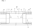
- the high-pressure hydrogen container 100 includes a cylinder body 10 made of metal and lid bodies 20 which are fastened and fixed to respective open ends of the cylinder body 10.
- the cylinder body 10 made of metal has a circular cylindrical shape and has the open ends.
- Female thread portions 15 are formed at the open ends.
- the female thread portions 15 are each a thread formed in an inner surface of the cylinder body 10.
- a cylinder portion 13 is provided to form an outer shell of a storage portion 12 that stores hydrogen.
- the cylinder portion 13 has a circularly cylindrical shape.
- each of the lid bodies 20 includes a first member 21 including the sealing portion 23 and a second member 22 including a male thread portion 25.
- the first members 21 close respective end portions of the storage portion 12 in the center-axis direction.
- Each of the first members 21 is formed into substantially a column.
- the first member 21 is formed to have a smaller outside diameter than the inside diameter of the sealing surface 16 of the cylinder body 10.
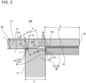
- a groove 21a is formed in an outer circumferential surface of the first member 21, a groove 21a (see Fig. 2 ) is formed.
- a sealing member 24 is fitted.
- the sealing member 24 is, for example, an O-ring; however, a sealing member having another configuration may also be employed.
- the sealing surface 16 is formed adjacent to the clearance portion 17 in the center-axis direction.
- the sealing surface 16 is formed to have a smaller inside diameter than that of the clearance portion 17 and the same inside diameter as that of the cylinder portion 13.
- the inside diameter of the sealing surface 16 can be appropriately set in conformity with the sealing portion 23 of the lid body 20.
- the sealing member 24 abuts the sealing surface 16, thereby sealing the storage portion 12 to prevent leakage of hydrogen from the storage portion 12.
- the thickness of part of the cylinder body 10 where the sealing surface 16 is a thickness H.
- the thickness H may be set different from the thickness t of the cylinder body 10 in the storage portion 12. That is, a step may be formed between the sealing surface 16 of the cylinder body 10 and the inner surface of the storage portion 12.
- the cylinder body 10 is made of, for example, low-alloy steel. That is, the cylinder body 10 is made of steel material such as chromium-molybdenum steel, nickel-chromium-molybdenum steel, manganese-chromium steel, manganese steel, or boron-added steel.
- the cylinder body 10 is formed in the shape of a circular cylinder having opening ends on both sides. At the inner circumferential surface at each of the both end portions, the female thread portion 15, the clearance portion 17 for a threading tool, and the sealing surface 16 are formed.
- the central portion of the cylinder body 10 is the cylinder portion 13 whose interior serves as the storage portion 12.
- the cylinder body 10 is formed in the shape of a circular cylinder having opening ends on both sides, however, the cylinder body 10 may is formed in the shape of a cylinder having an open end on one side and a bottom.
- the shape of the cylinder body 10 is not limited to the circularly cylindrical shape; that is, the cylinder body 10 can have another shape such as an elliptic cylindrical shape.
- a decarburized layer is removed from the inner circumferential surface of the cylinder body 10 by processing. After the removal of the decarburized layer, shot balls having a large mass are applied to the inner circumferential surface of the cylinder body 10, and residual compressive stress is thus applied to the inner circumferential surface. Residual compressive stress may also be applied to the cylinder portion 13, the sealing surface 16, the clearance portion 17, and the female thread portion 15.
- Hydrogen gas that leaks from the sealing portion 23 may stay in the clearance portion 17 and the female thread portion 15.
- the strength of stress generation portions M of the clearance portion 17 and the female thread portion 15 may be reduced by leaking hydrogen gas.
- an exhaust outlet (not illustrated) may be provided such that the exhaust outlet causes a space formed by the clearance portion 17 to communicate with the outside.
- a plurality of holes may be provided such that the holes cause the clearance portion 17 to communicate with the outside and thus gas in the clearance portion 17 to circulate with outside air.
- the lid body 20 is joined to an associated one of the end portions of the cylinder body 10.
- the lid body 20 is provided along the center-axis direction of the storage portion 12, and closes the end portion of the cylinder body 10.
- the lid body 20 includes the first member 21 which faces the storage portion 12 and the second member 22 which is fixed to the female thread portion 15 of the cylinder body 10.
- the first member 21 is called “plug” and closes the storage portion 12.
- the second member 22 is called "gland nut” and fixes the plug in the axial direction.
- the first member 21 contacts high-pressure hydrogen gas when the storage portion 12 is filled with the hydrogen gas, and is thus made of material having a high strength for low-temperature hydrogen gas. That is, the first member 21 is formed of material that can ensure a sufficient strength even under low temperature, and is, for example, formed of austenitic stainless steel.
- the first member 21 is formed into substantially a columnar shape such that at least the outer diameter of the first member 21 is smaller than the inside diameter of the sealing surface 16. An end face of the first member 21 forms a surface of the storage portion 12 in the axial direction.
- the first member 21 includes the sealing portion 23 at its outer circumferential surface.
- the sealing portion 23 includes the groove 21a and the sealing member 24.
- the O-ring is provided in the groove 21a.
- the outer circumferential surface of the sealing member 24 abuts the sealing surface 16 of the cylinder body 10.
- An area of the sealing surface 16 of the cylinder body 10 which the sealing member 24 abuts will be referred to as an abutting area 18.
- the sealing member 24 has an outside diameter that is set larger than the inside diameter of the sealing surface 16.
- the O-ring serving as the sealing member 24 is pressed by the sealing surface 16 and is filled in the groove 21a to close a gap between a bottom surface of the groove 21a and the sealing surface 16.
- a structure made up of the sealing portion 23 and the sealing surface 16 seals the storage portion 12 to prevent leakage of high-pressure hydrogen from the storage portion 12.
- the second member 22 includes the male thread portion 25 that is engaged with the female thread portion 15 of the cylinder body 10, and an end face 29 that abuts an end face 28 of the first member 21.
- the second member 22 blocks a force that is applied to the first member 21 in the axial direction from high-pressure hydrogen gas in the storage portion 12, and fixes the lid body 20 to the end portion of the cylinder body 10.
- the male thread portion 25 included in the second member 22 is engaged with the female thread portion 15 of the cylinder body 10, whereby that the position of the lid body 20 in the axial direction is fixed.
- the cylinder body 10 and the lid body 20 do not have surfaces that abut each other in the axial direction.
- a friction force between the sealing portion 23 of the first member 21 and the sealing surface 16 of the cylinder body 10 and a force due to the high-pressure hydrogen gas in the storage portion 12 are applied as an axial force.
- This axial force causes a fastening force to be generated between the female thread portion 15 and the male thread portion 25, whereby the lid body 20 is fixed to the end portion of the cylinder body 10.
- the first member 21 and the cylinder body 10 may be formed to abut each other in the axial direction.
- the second member 22 and the cylinder body 10 may be formed to abut each other in the axial direction. In this case, a fastening force between the female thread portion 15 and the male thread portion 25 is generated by an axial force that is generated when the first member 21 or the second member 22 and the cylinder body 10 abut each other in the axial direction.
- the second member 22 of the lid body 20 does not contact hydrogen gas. Nor is the second member 22 directly subjected to low temperature. Thus, in the second member 22, it suffices that the male thread portion 25, which serves as a fixation portion, can ensure an adequate strength. Low-alloy steel similar to that of the cylinder body 10 may be employed as material of the second member 22.
- the first member 21 and the second member 22 are separate members, can thus be formed of different materials, and can reduce costs while ensuring adequate durability.
- the first member 21 is formed of austenitic stainless steel
- the second member 22 is formed of material other than austenitic stainless steel. It is therefore possible to reduce the costs, and in addition ensure both an adequate fixing strength for the lid body 20 and adequate durability of the lid body 20.
- the first member 21 and the second member 22 may be formed as a single body. In this case, it is possible to reduce the number of components that form the high-pressure hydrogen container 100.
- the shorter one of the distance from the abutting area 18 to the clearance portion 17 and the distance from the abutting area 18 to the valley 15a is a distance L
- the distance from the abutting area 18 to the outer surface of the cylinder body 10 is a thickness H.
- the relationship between the distance L and the thickness H satisfies H ⁇ L. Since such a relationship is satisfied, it is possible to reduce occurrence of a damage such as cracking at the clearance portion 17 and the female thread portion 15 that is caused by hydrogen embrittlement occurring because of the effect of hydrogen in the storage portion 12 on the clearance portion 17 and the female thread portion 15.
- Fig. 3 illustrates a diffusion state of hydrogen into a metallic structure in the periphery of the sealing portion 23 in the high-pressure hydrogen container 100 according to Embodiment 1.
- Fig. 3 is a view based on analysis of diffusion of hydrogen gas in the storage portion 12 that diffuses into the metallic structure of the high-pressure hydrogen container under predetermined conditions.
- the high-pressure hydrogen container 100 according to Embodiment 1 since the cylinder body 10 is formed of low-alloy steel, hydrogen penetrates and diffuses into the metallic structure from the surface of the cylinder body 10 that is in contact with hydrogen gas filled in the storage portion 12.
- hydrogen diffuses from the abutting area 18 where the sealing portion 23 and the sealing surface 16 abut each other to the periphery of the sealing surface 16.
- hydrogen diffuses from the inner surface to the outer surface of the cylinder portion 13.
- hydrogen does not greatly diffuse in the axial direction of the cylinder body 10, as compared with the diffusion of hydrogen in the radial direction. Therefore, the hydrogen that has diffused into the metallic structure does not reach the clearance portion 17 or the female thread portion 15 of the cylinder body 10.
- Fig. 3 illustrates a diffusion state of hydrogen that diffuses into the metallic structure of each of the portions of the high-pressure hydrogen container 100, especially in the case where chromium-molybdenum steel (SCM435) is used and the storage portion 12 is filled with hydrogen gas of 95 MPa. Also, Fig. 3 illustrates the hydrogen that diffuses into the metallic structure of each of the portions of the high-pressure hydrogen container 100 and enters a steady state. The hydrogen in the storage portion 12 of the high-pressure hydrogen container 100 penetrates into the metallic structure with the passage of time, and then passes through the cylinder body 10. Fig. 3 illustrates the state in which the hydrogen passes through the cylinder portion 13 of the cylinder body 10, and flows out to an environment under atmospheric pressure, where the high-pressure hydrogen container 100 is installed.
- SCM435 chromium-molybdenum steel
- the hydrogen diffuses in a thickness direction thereof, but the content of the hydrogen that diffuses in the axial direction is low.
- the initial hydrogen concentration in the storage portion 12 is 0.181 [weight ppm] and the hydrogen diffusion coefficient D is 2.3 ⁇ 10 -10 [m 2 /s].
- Fig. 3 that illustrates the diffusion state of hydrogen in the high-pressure hydrogen container 100 is based on the diffusion flow rate J of hydrogen that diffuses into the metallic structure described below.
- J ⁇ s D ⁇ ⁇ ⁇ X + ⁇ p ⁇ p ⁇ X
- Fig. 4 illustrates a correlation between the pressure of hydrogen gas and the initial content of hydrogen that penetrates into the metallic structure.
- Fig. 4 is a diagram obtained by a high-pressure hydrogen permeation test and illustrates the relationship between the pressure P of hydrogen and the content C 0 of hydrogen that penetrates into chromium-molybdenum steel (SCM435).
- SCM435 chromium-molybdenum steel
- the content C 0 of hydrogen that penetrates into the material of chromium-molybdenum steel increases as the pressure P increases.
- the pressure in the storage portion 12 is set to 95 MPa.
- the initial content C 0 of the hydrogen is 0.181 weight ppm.
- Fig. 5 illustrates a correlation between the hydrogen diffusion coefficient D and the diffusion flow rate J.
- Fig. 5 is a diagram obtained by the same high-pressure hydrogen permeation test as in Fig. 4 .
- Hydrogen gas was introduced into a container formed of chromium-molybdenum steel (SCM435).
- the hydrogen diffusion coefficient D was obtained based on the behavior of the hydrogen from time at which the hydrogen was introduced into the container formed of chromium-molybdenum steel (SCM435) to time at which the hydrogen enters a steady state after passing through the container, and entered a steady state.
- the hydrogen concentration at a surface of the high-pressure hydrogen container 100 that contacts the outside air was set to 0 [weight ppm]. It should be noted that in Fig.
- the diffusion state of hydrogen into the high-pressure hydrogen container 100 as illustrated in Fig. 3 was obtained, where the solubility s was set to 0.076033 [ppm ⁇ mm/N 1/2 ], using the value of solubility of material having a strength and a structure which are similar to those of chromium-molybdenum steel (SCM435) (reference: Fujii T., Hazama T., Nakajima H., and Horita R.: Current Solutions to Hydrogen Problems in Steels, (1982),361, ASM International Materials, Park, Ohio ).
- the value of the hydrostatic stress effectiveness factor ⁇ p was obtained by linearly interpolating the coefficients for the following concentrations:
- Fig. 6 illustrates an example of a state in which stress is generated in the periphery of the female thread portion 15 in the high-pressure hydrogen container 100 according to Embodiment 1.
- Fig. 6 illustrates a hydrostatic stress distribution in the periphery of a portion where the cylinder body 10 and the lid body 20 are joined together, with hydrogen gas of 95 MPa filled in the storage portion 12 of the high-pressure hydrogen container 100.
- a certain level of stress is generated in the entirety of the cylinder body 10 and the lid body 20, by the pressure of high-pressure hydrogen in the storage portion 12. This stress is sufficiently low, as compared with the tensile strength of the material that form the cylinder body 10 and the lid body 20.
- a high stress ⁇ is generated at the bottom portion 17a of the clearance portion 17 and at the valley 15a of the female thread portion 15 which is located closer to the storage portion 12.
- the stress generation portions M of the high-pressure hydrogen container 100 are present at the female thread portion 15, the periphery of the sealing surface 16, and the clearance portion 17, and are portions and points where a stress higher than or equal to a predetermined stress ⁇ is generated.
- the predetermined stress ⁇ is, for example, one-third of the tensile strength of metal material.
- the bottom portion 17a of the clearance portion 17 and the valley 15a of the female thread portion 15 which is located closer to the storage portion 12 as illustrated in Fig. 6 correspond to the stress generation portions M. As illustrated in Fig.
- the bottom portion 17a of the clearance portion 17 that is the closest from the abutting area 18 is the stress generation portion M, and the distance L from the abutting area 18 to the stress generation portion M is set greater than the thickness H from the abutting area 18 to the outer surface of the cylinder body 10.
- the high-pressure hydrogen container is formed such that hydrogen passes through the cylinder body 10 and flows out of the cylinder body 10 to the outside before diffusing into the metallic structure and reaching the stress generation portion M. Therefore, the stress generation portion M is not affected by the hydrogen.
- H H ⁇ L
- K K ⁇ L
- k the coefficient
- K the coefficient
- the coefficient K varies depending on the material of the cylinder body 10, the distribution of stress that is generated in the cylinder body 10, and the hydrogen concentration in the storage portion 12.
- K the coefficient of the cylinder body 10.
- the pressure in the storage portion 12 is set lower than or equal to 100 MPa that is the pressure in the storage portion 12 when the high-pressure hydrogen container 100 is used, and a portion whose tensile strength is equal to or higher than 310 MPa that is one-third of the tensile strength of chromium-molybdenum steel of which the cylinder body 10 is formed, that is, 930 MPa, is the stress generation portion M.
- a stress of approximately 350 MPa is generated in the stress generation portion M at the bottom portion 17a of the clearance portion 17, and a stress of approximately 490 MPa is generated in the stress generation portion M at the valley 15a of the female thread portion 15.
- Fig. 7 illustrates a relationship between a stress that acts on the metal material and the number of cycles in which the stress acts.
- a repeated stress is applied to the metal material
- the metal material is broken.
- the repeated stress is reduced, the metal material is not broken even when the repeated stress is applied to the metal material in 10 6 to 10 7 cycles or more.
- the stress at this time will be referred to as "fatigue limit".
- the stress that can break the metal material is lower than in the case where the metal material is not affected by hydrogen.
- the repeated stress is less than or equal to the fatigue limit, the effect of hydrogen is negligible.
- the stress generation portion M a portion where a stress equal to or higher than the fatigue limit stress of the metal material is generated is determined as the stress generation portion M, whereby the distance L can be set shorter.
- the distance L By setting the distance L to the shortest possible distance, it is possible to reduce the size of a portion other than the storage portion 12, while ensuring a sufficient strength, even in an environment where the metal material is affected by hydrogen.
- the high-pressure hydrogen container 100 is filled with hydrogen at a high pressure of 75 MPa to 100 MPa, and supplies the hydrogen to, for example, the hydrogen tank of the vehicle.
- the pressure thus varies with a high frequency.
- the storage portion 12 of the high-pressure hydrogen container 100 needs to be kept at at least a higher pressure than 75 MPa. Therefore, after the high-pressure hydrogen container 100 supplies hydrogen to, for example, the hydrogen tank, and then the pressure in the storage portion 12 decreases, the storage portion 12 is supplied with liquid hydrogen or hydrogen gas, and the pressure therein is increased to a high pressure again.
- the cylinder body 10 of the high-pressure hydrogen container 100 is subjected to frequent pressure variations in a high-pressure range of, for example, 75 MPa to 100 MPa. Because of the pressure variations, the cylinder body 10 is in a state in which stress is constantly generated. Particularly, in the joining portion between the cylinder body 10 and the lid body 20, at which stress concentration is likely to occur, a high stress is generated, and is repeatedly subjected to a stress amplitude.
- the high-pressure hydrogen container 100 needs to have such a high strength as to prevent the high-pressure hydrogen container 100 from being broken, even when being repeatedly subjected to such a high stress amplitude as described above.
- the high-pressure hydrogen container 100 needs to have a high strength as described above, and is thus formed of low-alloy steel having a high tensile strength and a high fatigue strength.
- the low-alloy steel has a high tensile strength, high toughness, and thus a high fatigue strength.
- the toughness thereof is reduced, and as a result, the low-alloy steel may be broken.
- the existing high-pressure hydrogen container only the effect of hydrogen on a surface that is contact with the hydrogen is considered.
- the high-pressure hydrogen container 100 reduces lowering of the strength of a member which contacts hydrogen which diffuses into the metallic structure of the member, due to the effect of the hydrogen.
- the distance L from the stress generation portion M to the abutting area 18 between the sealing portion 23 and the sealing surface 16 is set adequately, whereby the high-pressure hydrogen container 100 can ensure the maximum size of the storage portion 12, and can increase the volumetric efficiency, while reducing lowering of its strength.
- the female thread portion 15 of the cylinder body 10 may be referred to as "joining portion”.
- the male thread portion 25 of the lid body 20 may be referred to as "fixation portion”.
- the female thread portion 15 and the male thread portion 25 in Embodiment 1 may have another joining structure.
- the cylinder body 10 and the lid body 20 may be joined together by other joining methods such as fitting, welding, or fixation using a bolt.
- the position of the stress generation portion M relative to the high-pressure hydrogen container 100 according to Embodiment 1 is changed. Even in that case, the high-pressure hydrogen container 100 can still ensure an adequate strength by satisfying the condition that the distance L is greater than the thickness H.
- the internal pressure of the high-pressure hydrogen container 100 is set to satisfy a predetermined condition, a stress that is generated in the cylinder body 10 is grasped, and the stress generation portion M is specified.
- the high-pressure hydrogen container 100 can ensure an adequate strength without being affected by stored hydrogen.
- the stress generation portion M is set as a portion where a stress greater than or equal to "one-third of the tensile stress of metal material" is generated.
- the stress generation portion M may be set as a portion where "a fatigue limit stress of metal material" is generated.
- the high-pressure hydrogen container 100 as illustrated in Fig. 6 is the same as that as illustrated in Fig. 3 , and has, for example, the following dimensions.
- the pressure in the storage portion 12 is 95 MPa
- Fig. 6 illustrates the state of the cylinder body 10 and the lid body 20 at the female thread portion 15 and the male thread portion.
- the distance L from the abutting area 18 to the stress generation portion M is 65.5 mm. This distance L is the distance from the abutting area 18 to the stress generation portion M which is the closest from the abutting area 18 in the case where the stress generation portion M is a portion where a stress greater than or equal to 310 MPa which is "one-third of the tensile stress of metal material" is generated.
- This distance L corresponds to the distance L1 indicated in Fig. 6 .
- the stress generation portion M is a portion where a stress of 465 MPa or higher, that is "a fatigue limit stress of metal material" is generated
- the distance L is the distance L2 indicated in Fig. 6 , that is, 86 mm.
- the high-pressure hydrogen container 100 can neglect the effect of hydrogen stored in the cylinder body 10 on the stress generation portion M, and can be still prevented from being broken, even when being subjected to a stress amplitude due to the high-pressure hydrogen in the cylinder body 10.
- the thickness H as indicated in Fig. 6 is equal to the thickness t of the cylinder body 10 in Embodiment 1, it is assumed that, for example, in the case where a step 13a (which has such a shape as illustrated by the dotted line in Fig. 2 ) is formed at the outer circumferential surface of the cylinder body 10 in Fig. 6 , the shortest distance h from the abutting area 18 to the step 13a corresponds to the thickness H.
- the state of stress which is generated with the pressure in the storage portion 12 applied is determined and the position of the stress generation portion M is specified.
- the stress generation portion M is a portion where the stress ⁇ is greater than or equal to one-third of the tensile stress of metal material, or is greater than or equal to the fatigue limit stress of metal material.
- a plurality of locations may be each applicable as the position of the stress generation portion M. In that case, one of the locations that is the shortest from the abutting area 18 which the sealing member 24 abuts is the position of the stress generation portion M.
- the high-pressure hydrogen container 100 has such a configuration as to satisfy H ⁇ L as the relationship between the thickness H and the distance L from the abutting area 18 to the stress generation portion M.
- the high-pressure hydrogen container 100 is designed such that the distance L is set to the shortest possible distance, while being greater than the thickness H.
- the stress generation portion M is not affected by hydrogen and its strength is not reduced.
- the shortest one of the distances between the abutting area 18 and the stress generation portions M is defined as the distance L, and the high-pressure hydrogen container 100 is configured in such a manner as to satisfy H ⁇ L.
- the high-pressure hydrogen container 100 does not have a configuration in which the first member 21 or the second member 22 abuts the cylinder body 10 in the axial direction.
- the stress generation portion M is located at the position of the clearance portion 17 or the valley 15a of the female thread portion 15.
- a high-pressure hydrogen container is configured such that the first member 21 and the cylinder body 10 abut each other in the axial direction, the stress generation portion M is located in the periphery of the abutting portion in the axial direction. Therefore, it is preferable that the distance between the abutting area 18 and the abutting portion in the axial direction be the distance L, and the high-pressure hydrogen container is configured to satisfy H ⁇ L.
Landscapes
- Engineering & Computer Science (AREA)
- General Engineering & Computer Science (AREA)
- Mechanical Engineering (AREA)
- Filling Or Discharging Of Gas Storage Vessels (AREA)
- Pressure Vessels And Lids Thereof (AREA)
Applications Claiming Priority (2)
| Application Number | Priority Date | Filing Date | Title |
|---|---|---|---|
| JP2021016001 | 2021-02-03 | ||
| PCT/JP2022/003190 WO2022168737A1 (ja) | 2021-02-03 | 2022-01-28 | 高圧水素容器 |
Publications (2)
| Publication Number | Publication Date |
|---|---|
| EP4290102A1 true EP4290102A1 (de) | 2023-12-13 |
| EP4290102A4 EP4290102A4 (de) | 2024-06-26 |
Family
ID=82741537
Family Applications (1)
| Application Number | Title | Priority Date | Filing Date |
|---|---|---|---|
| EP22749611.4A Pending EP4290102A4 (de) | 2021-02-03 | 2022-01-28 | Hochdruckwasserstoffbehälter |
Country Status (8)
| Country | Link |
|---|---|
| US (1) | US12264778B2 (de) |
| EP (1) | EP4290102A4 (de) |
| JP (2) | JP7269391B2 (de) |
| KR (1) | KR102886985B1 (de) |
| CN (1) | CN116806293B (de) |
| AU (1) | AU2022217967B2 (de) |
| CL (1) | CL2023001954A1 (de) |
| WO (1) | WO2022168737A1 (de) |
Cited By (1)
| Publication number | Priority date | Publication date | Assignee | Title |
|---|---|---|---|---|
| FR3158347A1 (fr) | 2024-01-12 | 2025-07-18 | Vallourec Oil And Gas France | Réservoir de gaz sous pression |
Families Citing this family (2)
| Publication number | Priority date | Publication date | Assignee | Title |
|---|---|---|---|---|
| KR102886985B1 (ko) * | 2021-02-03 | 2025-11-17 | 제이에프이 스틸 가부시키가이샤 | 고압 수소 용기 |
| AT528153B1 (de) * | 2024-01-30 | 2026-02-15 | Bhdt Gmbh | H2-Hochdruckbehälter |
Family Cites Families (10)
| Publication number | Priority date | Publication date | Assignee | Title |
|---|---|---|---|---|
| JPS63145058U (de) * | 1987-03-13 | 1988-09-26 | ||
| JP6781892B2 (ja) | 2016-02-12 | 2020-11-11 | 株式会社日本製鋼所 | 蓄圧容器 |
| JP7479622B2 (ja) | 2017-10-27 | 2024-05-09 | 日本製鋼所M&E株式会社 | 蓄圧容器 |
| CN108679222A (zh) * | 2018-05-07 | 2018-10-19 | 北京特种机械研究所 | 一种模拟深海环境的耐压罐 |
| JP7100553B2 (ja) | 2018-10-02 | 2022-07-13 | 日本製鋼所M&E株式会社 | 水素蓄圧器 |
| JP7270203B2 (ja) | 2018-10-17 | 2023-05-10 | 日本製鋼所M&E株式会社 | ガス蓄圧器 |
| CN209856366U (zh) * | 2019-04-19 | 2019-12-27 | 德阳四创科技有限公司 | 压力容器密封结构 |
| CN110285315B (zh) * | 2019-05-28 | 2024-08-13 | 江阴市富仁高科股份有限公司 | 一种两端带密封结构的高压储氢容器 |
| CN111927951B (zh) * | 2020-09-07 | 2024-06-14 | 中国地震局地质研究所 | 静密封结构以及具有该静密封结构的压力容器 |
| KR102886985B1 (ko) | 2021-02-03 | 2025-11-17 | 제이에프이 스틸 가부시키가이샤 | 고압 수소 용기 |
-
2022
- 2022-01-28 KR KR1020237021550A patent/KR102886985B1/ko active Active
- 2022-01-28 US US18/266,301 patent/US12264778B2/en active Active
- 2022-01-28 AU AU2022217967A patent/AU2022217967B2/en active Active
- 2022-01-28 WO PCT/JP2022/003190 patent/WO2022168737A1/ja not_active Ceased
- 2022-01-28 EP EP22749611.4A patent/EP4290102A4/de active Pending
- 2022-01-28 CN CN202280011588.3A patent/CN116806293B/zh active Active
- 2022-01-28 JP JP2022011354A patent/JP7269391B2/ja active Active
-
2023
- 2023-04-21 JP JP2023070119A patent/JP2023103269A/ja active Pending
- 2023-06-30 CL CL2023001954A patent/CL2023001954A1/es unknown
Cited By (2)
| Publication number | Priority date | Publication date | Assignee | Title |
|---|---|---|---|---|
| FR3158347A1 (fr) | 2024-01-12 | 2025-07-18 | Vallourec Oil And Gas France | Réservoir de gaz sous pression |
| FR3158346A1 (fr) * | 2024-01-12 | 2025-07-18 | Vallourec Oil And Gas France | Réservoir de gaz sous pression |
Also Published As
| Publication number | Publication date |
|---|---|
| WO2022168737A1 (ja) | 2022-08-11 |
| EP4290102A4 (de) | 2024-06-26 |
| CN116806293A (zh) | 2023-09-26 |
| NZ801592A (en) | 2025-07-25 |
| AU2022217967B2 (en) | 2024-11-14 |
| KR20230110347A (ko) | 2023-07-21 |
| JP2022119198A (ja) | 2022-08-16 |
| AU2022217967A1 (en) | 2023-07-20 |
| CL2023001954A1 (es) | 2024-02-16 |
| JP7269391B2 (ja) | 2023-05-08 |
| JP2023103269A (ja) | 2023-07-26 |
| US20240027023A1 (en) | 2024-01-25 |
| CN116806293B (zh) | 2026-05-12 |
| KR102886985B1 (ko) | 2025-11-17 |
| US12264778B2 (en) | 2025-04-01 |
Similar Documents
| Publication | Publication Date | Title |
|---|---|---|
| US12264778B2 (en) | High-pressure hydrogen container | |
| US6494183B2 (en) | Common rail for diesel engine | |
| US20240369184A1 (en) | Pressure Vessel, Pressure Vessel System, Motor Vehicle and Method for Forming Ribs | |
| EP3415806A1 (de) | Druckspeicherbehälter | |
| US5735551A (en) | Pipe repair apparatus and method | |
| KR102208902B1 (ko) | 파이프 조인트 | |
| EP3290683B1 (de) | Anschlussdichtungsanordnung für kraftstoffverteiler für benzinmotor mit direkteinspritzung | |
| JP2007199024A (ja) | 鉄鋼材料の遅れ破壊試験方法、ボルトの遅れ破壊方法及び遅れ破壊試験用治具 | |
| US20090283154A1 (en) | Fluid supply valve attachment device | |
| JP5077688B2 (ja) | 流体供給弁組付装置 | |
| Liu | Extended design philosophy of hydrogen transport pipelines | |
| CN106574588A (zh) | 汽油直喷发动机用燃料轨的端头密封构造 | |
| US8485535B2 (en) | Sealing gland for ribbon-shaped probe | |
| KR100937058B1 (ko) | 자동차용 고압 연료 분사 축압 분배기 및 그 제조 방법 | |
| KR102828675B1 (ko) | 고압 가스용 용기 및 그 제조 방법 | |
| RU2811853C1 (ru) | Водородный резервуар высокого давления | |
| US20250216029A1 (en) | High-pressure fluid storage container with oxidation resistance/hydrogen embrittlement resistance through surface treatment | |
| KR102901551B1 (ko) | 나사 형성 강관 및 그 제조 방법 | |
| WO2024188814A1 (en) | Pressure vessel for storing a pressurised fluid, such as hydrogen | |
| Lassesen et al. | NORSOK L-005—Compact Flanged Connections (CFC): The New Flange Standard | |
| US20240060581A1 (en) | High pressure tube end form such as incorporated into a hydrogen fuel fill tube | |
| Schwarz et al. | Component Dimensioning in Hydrogen Environment | |
| Groysman et al. | Hydrogen damage and prevention in the oil refinery | |
| Becht IV | Perspectives on Fatigue Design of Bellows | |
| Jadhav et al. | Design considerations for plastic fuel rail and its benefits |
Legal Events
| Date | Code | Title | Description |
|---|---|---|---|
| STAA | Information on the status of an ep patent application or granted ep patent |
Free format text: STATUS: THE INTERNATIONAL PUBLICATION HAS BEEN MADE |
|
| PUAI | Public reference made under article 153(3) epc to a published international application that has entered the european phase |
Free format text: ORIGINAL CODE: 0009012 |
|
| STAA | Information on the status of an ep patent application or granted ep patent |
Free format text: STATUS: REQUEST FOR EXAMINATION WAS MADE |
|
| 17P | Request for examination filed |
Effective date: 20230721 |
|
| AK | Designated contracting states |
Kind code of ref document: A1 Designated state(s): AL AT BE BG CH CY CZ DE DK EE ES FI FR GB GR HR HU IE IS IT LI LT LU LV MC MK MT NL NO PL PT RO RS SE SI SK SM TR |
|
| DAV | Request for validation of the european patent (deleted) | ||
| DAX | Request for extension of the european patent (deleted) | ||
| A4 | Supplementary search report drawn up and despatched |
Effective date: 20240527 |
|
| RIC1 | Information provided on ipc code assigned before grant |
Ipc: F17C 13/00 20060101ALI20240522BHEP Ipc: F16J 12/00 20060101AFI20240522BHEP |
|
| STAA | Information on the status of an ep patent application or granted ep patent |
Free format text: STATUS: EXAMINATION IS IN PROGRESS |
|
| 17Q | First examination report despatched |
Effective date: 20250430 |