EP4289662A2 - Motor vehicle - Google Patents
Motor vehicle Download PDFInfo
- Publication number
- EP4289662A2 EP4289662A2 EP23177567.7A EP23177567A EP4289662A2 EP 4289662 A2 EP4289662 A2 EP 4289662A2 EP 23177567 A EP23177567 A EP 23177567A EP 4289662 A2 EP4289662 A2 EP 4289662A2
- Authority
- EP
- European Patent Office
- Prior art keywords
- control
- driver
- motor vehicle
- operated
- support structure
- Prior art date
- Legal status (The legal status is an assumption and is not a legal conclusion. Google has not performed a legal analysis and makes no representation as to the accuracy of the status listed.)
- Pending
Links
Images



Classifications
-
- B—PERFORMING OPERATIONS; TRANSPORTING
- B62—LAND VEHICLES FOR TRAVELLING OTHERWISE THAN ON RAILS
- B62D—MOTOR VEHICLES; TRAILERS
- B62D63/00—Motor vehicles or trailers not otherwise provided for
- B62D63/02—Motor vehicles
- B62D63/04—Component parts or accessories
-
- B—PERFORMING OPERATIONS; TRANSPORTING
- B60—VEHICLES IN GENERAL
- B60N—SEATS SPECIALLY ADAPTED FOR VEHICLES; VEHICLE PASSENGER ACCOMMODATION NOT OTHERWISE PROVIDED FOR
- B60N2/00—Seats specially adapted for vehicles; Arrangement or mounting of seats in vehicles
- B60N2/64—Back-rests or cushions
- B60N2/646—Back-rests or cushions shape of the cushion
-
- B—PERFORMING OPERATIONS; TRANSPORTING
- B60—VEHICLES IN GENERAL
- B60K—ARRANGEMENT OR MOUNTING OF PROPULSION UNITS OR OF TRANSMISSIONS IN VEHICLES; ARRANGEMENT OR MOUNTING OF PLURAL DIVERSE PRIME-MOVERS IN VEHICLES; AUXILIARY DRIVES FOR VEHICLES; INSTRUMENTATION OR DASHBOARDS FOR VEHICLES; ARRANGEMENTS IN CONNECTION WITH COOLING, AIR INTAKE, GAS EXHAUST OR FUEL SUPPLY OF PROPULSION UNITS IN VEHICLES
- B60K26/00—Arrangement or mounting of propulsion-unit control devices in vehicles
- B60K26/02—Arrangement or mounting of propulsion-unit control devices in vehicles of initiating means or elements
-
- B—PERFORMING OPERATIONS; TRANSPORTING
- B60—VEHICLES IN GENERAL
- B60N—SEATS SPECIALLY ADAPTED FOR VEHICLES; VEHICLE PASSENGER ACCOMMODATION NOT OTHERWISE PROVIDED FOR
- B60N2/00—Seats specially adapted for vehicles; Arrangement or mounting of seats in vehicles
- B60N2/005—Arrangement or mounting of seats in vehicles, e.g. dismountable auxiliary seats
- B60N2/01—Arrangement of seats relative to one another
-
- B—PERFORMING OPERATIONS; TRANSPORTING
- B60—VEHICLES IN GENERAL
- B60N—SEATS SPECIALLY ADAPTED FOR VEHICLES; VEHICLE PASSENGER ACCOMMODATION NOT OTHERWISE PROVIDED FOR
- B60N2/00—Seats specially adapted for vehicles; Arrangement or mounting of seats in vehicles
- B60N2/24—Seats specially adapted for vehicles; Arrangement or mounting of seats in vehicles for particular purposes or particular vehicles
-
- B—PERFORMING OPERATIONS; TRANSPORTING
- B60—VEHICLES IN GENERAL
- B60N—SEATS SPECIALLY ADAPTED FOR VEHICLES; VEHICLE PASSENGER ACCOMMODATION NOT OTHERWISE PROVIDED FOR
- B60N2/00—Seats specially adapted for vehicles; Arrangement or mounting of seats in vehicles
- B60N2/24—Seats specially adapted for vehicles; Arrangement or mounting of seats in vehicles for particular purposes or particular vehicles
- B60N2/38—Seats specially adapted for vehicles; Arrangement or mounting of seats in vehicles for particular purposes or particular vehicles specially constructed for use on tractors or like off-road vehicles
- B60N2/40—Seats specially adapted for vehicles; Arrangement or mounting of seats in vehicles for particular purposes or particular vehicles specially constructed for use on tractors or like off-road vehicles saddle type
-
- B—PERFORMING OPERATIONS; TRANSPORTING
- B60—VEHICLES IN GENERAL
- B60N—SEATS SPECIALLY ADAPTED FOR VEHICLES; VEHICLE PASSENGER ACCOMMODATION NOT OTHERWISE PROVIDED FOR
- B60N2/00—Seats specially adapted for vehicles; Arrangement or mounting of seats in vehicles
- B60N2/75—Arm-rests
- B60N2/79—Adaptations for additional use of the arm-rests
- B60N2/797—Adaptations for additional use of the arm-rests for use as electrical control means, e.g. switches
-
- B—PERFORMING OPERATIONS; TRANSPORTING
- B60—VEHICLES IN GENERAL
- B60T—VEHICLE BRAKE CONTROL SYSTEMS OR PARTS THEREOF; BRAKE CONTROL SYSTEMS OR PARTS THEREOF, IN GENERAL; ARRANGEMENT OF BRAKING ELEMENTS ON VEHICLES IN GENERAL; PORTABLE DEVICES FOR PREVENTING UNWANTED MOVEMENT OF VEHICLES; VEHICLE MODIFICATIONS TO FACILITATE COOLING OF BRAKES
- B60T7/00—Brake-action initiating means
- B60T7/02—Brake-action initiating means for personal initiation
- B60T7/04—Brake-action initiating means for personal initiation foot actuated
-
- B—PERFORMING OPERATIONS; TRANSPORTING
- B60—VEHICLES IN GENERAL
- B60T—VEHICLE BRAKE CONTROL SYSTEMS OR PARTS THEREOF; BRAKE CONTROL SYSTEMS OR PARTS THEREOF, IN GENERAL; ARRANGEMENT OF BRAKING ELEMENTS ON VEHICLES IN GENERAL; PORTABLE DEVICES FOR PREVENTING UNWANTED MOVEMENT OF VEHICLES; VEHICLE MODIFICATIONS TO FACILITATE COOLING OF BRAKES
- B60T7/00—Brake-action initiating means
- B60T7/02—Brake-action initiating means for personal initiation
- B60T7/08—Brake-action initiating means for personal initiation hand actuated
- B60T7/10—Disposition of hand control
- B60T7/102—Disposition of hand control by means of a tilting lever
-
- B—PERFORMING OPERATIONS; TRANSPORTING
- B62—LAND VEHICLES FOR TRAVELLING OTHERWISE THAN ON RAILS
- B62D—MOTOR VEHICLES; TRAILERS
- B62D1/00—Steering controls, i.e. means for initiating a change of direction of the vehicle
- B62D1/02—Steering controls, i.e. means for initiating a change of direction of the vehicle vehicle-mounted
- B62D1/12—Hand levers
-
- B—PERFORMING OPERATIONS; TRANSPORTING
- B62—LAND VEHICLES FOR TRAVELLING OTHERWISE THAN ON RAILS
- B62D—MOTOR VEHICLES; TRAILERS
- B62D5/00—Power-assisted or power-driven steering
- B62D5/001—Mechanical components or aspects of steer-by-wire systems, not otherwise provided for in this maingroup
-
- B—PERFORMING OPERATIONS; TRANSPORTING
- B60—VEHICLES IN GENERAL
- B60K—ARRANGEMENT OR MOUNTING OF PROPULSION UNITS OR OF TRANSMISSIONS IN VEHICLES; ARRANGEMENT OR MOUNTING OF PLURAL DIVERSE PRIME-MOVERS IN VEHICLES; AUXILIARY DRIVES FOR VEHICLES; INSTRUMENTATION OR DASHBOARDS FOR VEHICLES; ARRANGEMENTS IN CONNECTION WITH COOLING, AIR INTAKE, GAS EXHAUST OR FUEL SUPPLY OF PROPULSION UNITS IN VEHICLES
- B60K26/00—Arrangement or mounting of propulsion-unit control devices in vehicles
- B60K26/02—Arrangement or mounting of propulsion-unit control devices in vehicles of initiating means or elements
- B60K2026/026—Adjusting of accelerator pedal positions
Definitions
- the invention relates to a motor vehicle.
- Motor vehicles which comprise a body defining a passenger compartment as well as a plurality of driving systems and of respective controls, which can be operated by a driver in order to adjust the operation of the corresponding driving systems.
- example of driving systems consist of:
- the passenger compartment comprises, in turn, at least a pair of front seats and is delimited, at the front, by a dashboard and by a windshield arranged in front of the front seats, with reference to a normal moving direction of the motor vehicle.
- one of the front seats defines a cockpit for a driver.
- the driver can operate the steering wheel and the gear lever with his/her own hands, the clutch pedal with the left foot and, alternatively, either the accelerator pedal or the brake pedal with the right foot.
- the "drive by wire” connection comprises:
- the object of the invention is to provide a motor vehicle, which is capable of fulfilling at least one of the needs discussed above.
- number 1 indicates a motor vehicle comprising a body 2 defining a passenger compartment 3 and a plurality of wheels 4.
- the motor vehicle 1 is a top-of-the-range motor vehicle designed both for a conventional urban/suburban use and for a racing track use.
- the motor vehicle 1 further comprises, in a known manner and as merely schematically shown in Figure 5 , a driving system 5, which can be operated so as to drive the motor vehicle 1 according to a trajectory desired by the driver 19 and with a speed that can be adjusted by the driver 19.
- a driving system 5 which can be operated so as to drive the motor vehicle 1 according to a trajectory desired by the driver 19 and with a speed that can be adjusted by the driver 19.
- the driving system 5 basically comprises, as merely schematically shown in Figure 5 :
- the engine 6, the steering system 7 and the braking system 8 comprise respective input members 9, 10, 11, which can be operated so as to adjust the respective values of torque, inclination angle and braking torque.
- the motor vehicle 1 further comprises:
- control unit 15 is solely electronically - and not mechanically - connected to the interface 20 and to the input members 9, 10, 11, so as to obtain a "drive by wire” driving system.
- the motor vehicle 1 advantageously comprises a support structure 30 ( Figures 2 to 4 ) defining a horseman-like driving position for the driver 19, who is in a prone position; the interface 10 comprises, in turn:
- the controls 31, 32 are arranged in front of the controls 33, 34.
- the driver 19 is in a prone position on the structure 30 and grasps the controls 31, 32 with the hands 21, 22 and holds the feet 31, 32 in the area of the controls 33, 34.
- the support structure 30 is accommodated inside the passenger compartment 3 and basically comprises:
- the area 37 is arranged in front of the seat 36, is inclined relative to the direction X and extends at progressively increasing distances from the seat 36, moving in the same direction as the normal moving direction of the motor vehicle 1.
- the flanks 38 define resting surfaces 39 for the legs 40 of the driver 19.
- the support structure 30 further comprises a pair of areas 41, on which respective arms 42 of the driver 19 can rest.
- the areas 41 are defined by the surface 35, are spaced apart parallel to the axis Y and define respective extensions of the area 37 on the side opposite the seat 36.
- the controls 31, 32 are arranged in the area of respective areas 41, so that they can be grasped by respective hands 21, 22 of the driver 19 in a prone position.
- the controls 33, 34 are articulated on respective flanks 38, so that they can be operated by respective feet 23, 24 of the driver 19 in a prone position.
- the control unit 15 is programmed to transform the activations imparted to the controls 31, 32 into respective operating signals for the input member 10 of the steering system 7, in case of actuation of only one of the controls 31, 32.
- control unit 15 is programmed to:
- the control unit 15 is programmed to transform the activations imparted to the controls 31, 32 into respective operating signals for the input member 11 of the braking system 8, in case of actuation of both controls 31, 32.
- control unit 15 is programmed to generate an operating signal for the input member 11 of the braking system 8 corresponding to the generation of the maximum braking torque, in case of activation of both controls 31, 32, in case an emergency braking has to be carried out.
- the control unit 15 is programmed to transform the activations imparted to the control 34 into an operating signal for the input member 9 of the engine 6.
- control unit 15 is programmed to generate an operating signal for the input member 9 of the engine 6 corresponding to the generation of a torque proportional to the activation imparted to the control 34.
- control 34 fulfils the function of an accelerator.
- the control unit 15 is programmed to generate an operating signal for the input member 11 of the braking system 8 corresponding to the generation of a braking torque proportional to the activation imparted to the control 33.
- control 33 fulfils the function of an brake.
- the controls 31, 32 are joysticks and can be operated parallel to the axis X.
- the controls 31, 32 project from the respective areas 41.
- the controls 31, 33 are arranged on a right side ( Figure 2 ) and the controls 32, 34 are arranged on a left side ( Figure 3 ) of the support structure 30, moving in the same direction as the normal driving direction of the motor vehicle 1 along the axis X.
- the controls 33, 34 are pedals 27, 28 hinged to the support structure 30 around respective axes A, B, which are parallel to and staggered relative to one another and are parallel to the axis Y.
- the axis A is arranged in front of the axis B.
- the pedal 27 is arranged under the axis A and lies on a plane P forming an acute angle ⁇ with the axis Z ( Figure 2 ) .
- the pedal 28 is arranged above the axis B and forms an acute angle ⁇ with the axis Z ( Figure 3 ).
- the control unit 15 is programmed to generate an operating signal for the input member 11 of the braking system 8 corresponding to the generation of a braking torque increasing as the angle ⁇ imparted to the control 33 decreases.
- the control unit 15 is programmed to generate an operating signal for the input member 9 of the engine 6 corresponding to the generation of a torque increasing as the angle ⁇ imparted to the control 34 increases.
- the interface 20 further comprises a plurality of buttons, which can be operated by the driver 19, are operatively connected to the control unit 15 and are arranged on the support structure 30.
- the motor vehicle 1 further comprises:
- the passenger compartment 3 further comprises ( Figure 1 ) :
- the driver 19 is located on the support structure 30 in a prone position.
- the driver 19 sits on the seat 36 and lays the stomach 25 on the area 37 and the arms 42 on the areas 41.
- the driver 19 grasps the controls 31, 32 with the left and right hands 21, 22, respectively, and holds the left and right feet 23, 24 on the respective pedals 27, 28 defining the respective controls 33, 34.
- control unit 15 is programmed to transform the activations imparted by the driver 19 to the controls 31, 32, 33 and 34 into respective operating signals for the input members 9, 10, 11.
- control unit 15 in case of activation of the sole control 31, the control unit 15 generates an operating signal for the input member 10 of the steering system 7 corresponding to an increase in the radius of curvature, in case of a left bend, or to a reduction in the radius of curvature, in case of a right bend, in case of activation of the sole control 31.
- control unit 10 is programmed to generate an operating signal for the input member 10 corresponding to a reduction in the radius of curvature, in case of a right bend, or to an increase in the radius of curvature, in case of a left bend.
- the driver 19 operates both controls 31, 32.
- the control unit 15 is programmed to generate an operating signal for the input member 11 of the braking system 8 corresponding to the generation of the maximum braking torque acting upon the wheels 4.
- the control unit 15 is programmed to generate an operating signal for the input member 9 of the engine 6 corresponding to the generation of a torque increasing as the angle ⁇ imparted to the control 34 increases.
- control unit 15 is programmed to generate a haptic feedback, which prevents the acceleration from increasing, requesting a greater effort to the user 19.
- the control unit 15 is programmed to generate an operating signal for the input member 11 of the braking system 8 corresponding to the generation of a braking torque increasing as the angle ⁇ imparted to the control 33 decreases.
- the motor vehicle 1 comprises a support structure 30 defining a horseman-like driving position for the driver 19, who is in a prone position. From this driving position, the driver 19 can operate the controls 31, 32 with the hands 21, 22, namely the left and right hand respectively, and the controls 33, 34 with the feet 23, 24, namely the left and right foot respectively, thus controlling the driving systems 5 of the motor vehicle 1.
- the driving and learning easiness can be increased, for the prone position allows for a more aware and a more easily visually controllable perception of the trajectories set and/or to be set.
- the controls 31, 32 allow the driver 19 to control the steering system 7 through the hands 21, 22, while the controls 33, 34 allow the driver 19 to control the braking system 8 and the engine 6 through the feet 23, 24.
- the pedal 27 serving as brake is arranged under the axis B ( Figure 3 ).
- the support structure 30 could comprise a control 31, 32 and one single control 33, 34.
- the front region 50 could not comprise the seat and the support structure 30 could be arranged at the centre along the direction Y within the front region.
Landscapes
- Engineering & Computer Science (AREA)
- Transportation (AREA)
- Mechanical Engineering (AREA)
- Chemical & Material Sciences (AREA)
- Combustion & Propulsion (AREA)
- Aviation & Aerospace Engineering (AREA)
- Auxiliary Drives, Propulsion Controls, And Safety Devices (AREA)
- Electric Propulsion And Braking For Vehicles (AREA)
- Mechanical Control Devices (AREA)
- Arrangement Or Mounting Of Propulsion Units For Vehicles (AREA)
- Automatic Cycles, And Cycles In General (AREA)
Abstract
Description
- This patent application claims priority from
Italian patent application no. 102022000012170 filed on June 8, 2022 - The invention relates to a motor vehicle.
- Motor vehicles are known, which comprise a body defining a passenger compartment as well as a plurality of driving systems and of respective controls, which can be operated by a driver in order to adjust the operation of the corresponding driving systems.
- More in detail, example of driving systems consist of:
- an engine comprising an output shaft operatively connected to a pair of drive wheels of the motor vehicle;
- a gearbox interposed between the output shaft of the engine and the drive wheels and capable of being operated in order to obtain a plurality of gear ratios between the output shaft of the engine and the drive wheels; and
- a braking system, which can be activated in order to exert a braking torque upon the aforesaid wheels.
- Corresponding non-limiting examples of the controls consist of:
- a steering wheel arranged inside the passenger compartment and capable of being operated by the hands of the driver in order to steer the wheels;
- an accelerator pedal, which can be operated by a foot of the driver in order to adjust the torque generated by the engine;
- a clutch pedal, which can be operated by the foot of the driver in order to uncouple the output shaft of the engine and the drive wheels;
- a lever, which can be operated by a hand of the driver in order to shift gears in the gearbox; and
- a brake pedal, which can be operated by the foot of the driver in order to operate the braking system of the motor vehicle.
- The passenger compartment comprises, in turn, at least a pair of front seats and is delimited, at the front, by a dashboard and by a windshield arranged in front of the front seats, with reference to a normal moving direction of the motor vehicle.
- In a known manner, one of the front seats defines a cockpit for a driver.
- In this cockpit, the driver can operate the steering wheel and the gear lever with his/her own hands, the clutch pedal with the left foot and, alternatively, either the accelerator pedal or the brake pedal with the right foot.
- Traditional motor vehicles have mechanical connections between the controls and input members of respective driving systems.
- Solutions of the "drive by wire" kind were recently introduced in order to turn, in a functional manner and without mechanical members, the commands desired by the driver into corresponding operating signals for input members of respective driving systems.
- More in detail, the "drive by wire" connection comprises:
- an interface, which can be operated by the driver and is designed to receive the command desired by the driver; and
- a control unit, which is functionally connected to the interface and to the input members of the respective driving systems and is programmed to convert the desired command into an actuation signal for the operating member of the respective driving system.
- When dealing with said "drive by wire" solutions, the automotive industry needs to improve the emotional involvement of the driver.
- Furthermore, manufacturers need to increase the easiness of driving and of learning particularly challenging driving manoeuvres.
- The object of the invention is to provide a motor vehicle, which is capable of fulfilling at least one of the needs discussed above.
- The aforesaid object is reached by the invention, as it relates to a motor vehicle as defined in
claim 1, 2 or 14. - The invention will be best understood upon perusal of the following detailed description of two preferred embodiments, which are provided by way of non-limiting example, with reference to the accompanying drawings, wherein:
-
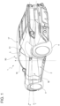
figure 1 is a perspective view of a motor vehicle according to the invention; -
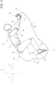
figure 2 is a side view, on a first side and on a larger scale, of a cockpit of the motor vehicle offigure 1 ; -
figure 3 is a side view, on a second side opposite the first one, of the cockpit offigure 2 ; -
figure 4 is a top view of the cockpit offigures 2 and3 ; and -
figure 5 schematically shows some components of the motor vehicle offigures 1 to 4 . - With reference to the accompanying Figures, number 1 indicates a motor vehicle comprising a
body 2 defining apassenger compartment 3 and a plurality ofwheels 4. - The motor vehicle 1 is a top-of-the-range motor vehicle designed both for a conventional urban/suburban use and for a racing track use.
- Hereinafter, expressions such as "at the top", "at the bottom", "at the front", "at the back" and others similar to them are used with reference to a normal moving direction of the motor vehicle 1.
- Furthermore, it is possible to define:
- a longitudinal axis X integral to the motor vehicle 1, which, in use, is horizontal and parallel to a normal moving direction of the motor vehicle 1;
- a transverse axis X integral to the vehicle 1, which, in use, is horizontal and orthogonal to the axis X; and
- an axis Z integral to the vehicle 1, which, in use, is vertical and orthogonal to the axes X, Y.
- The motor vehicle 1 further comprises, in a known manner and as merely schematically shown in
Figure 5 , adriving system 5, which can be operated so as to drive the motor vehicle 1 according to a trajectory desired by thedriver 19 and with a speed that can be adjusted by thedriver 19. - The
driving system 5 basically comprises, as merely schematically shown inFigure 5 : - an engine 6, which can be operated so as to generate a torque exerted upon the
drive wheels 4; - a
steering system 7, which can be operated so as to adjust the inclination angle between the lying planes of thefront wheels 4 and the axis X in order to drive the motor vehicle 1 along a curved trajectory; and - a braking system 8, which can be operated so as to generate a braking torque exerted upon some of or all the
wheels 4. - The engine 6, the
steering system 7 and the braking system 8 compriserespective input members - With reference to
Figure 5 , the motor vehicle 1 further comprises: - an
interface 20 configured to receive, from thedriver 19, a plurality of commands concerning the trajectory and the desired speed of the motor vehicle 1; and - a
control unit 15, which is operatively connected to theinterface 20 and theinput members driver 19 into corresponding laws of actuation for theinput members - It should be pointed out that the
control unit 15 is solely electronically - and not mechanically - connected to theinterface 20 and to theinput members - The motor vehicle 1 advantageously comprises a support structure 30 (
Figures 2 to 4 ) defining a horseman-like driving position for thedriver 19, who is in a prone position; theinterface 10 comprises, in turn: - a pair of
controls left hand 21 and by aright hand 22 of thedriver 19, respectively; and - a pair of
controls left foot 23 and by aright foot 24 of thedriver 19, respectively; - The
controls controls - The
driver 19 is in a prone position on thestructure 30 and grasps thecontrols hands feet controls - The
support structure 30 is accommodated inside thepassenger compartment 3 and basically comprises: - an
upper end surface 35 defining aseat 36 for thedriver 19 and anarea 37 on which astomach 25 of thedriver 19 rests; and - a pair of
flanks 38 opposite one another, between which thesurface 35 extends and which laterally delimit thesupport structure 30. - In particular, the
area 37 is arranged in front of theseat 36, is inclined relative to the direction X and extends at progressively increasing distances from theseat 36, moving in the same direction as the normal moving direction of the motor vehicle 1. - The
flanks 38 defineresting surfaces 39 for the legs 40 of thedriver 19. - The
support structure 30 further comprises a pair ofareas 41, on whichrespective arms 42 of thedriver 19 can rest. - The
areas 41 are defined by thesurface 35, are spaced apart parallel to the axis Y and define respective extensions of thearea 37 on the side opposite theseat 36. - The
controls respective areas 41, so that they can be grasped byrespective hands driver 19 in a prone position. - The
controls respective flanks 38, so that they can be operated byrespective feet driver 19 in a prone position. - The
control unit 15 is programmed to transform the activations imparted to thecontrols input member 10 of thesteering system 7, in case of actuation of only one of thecontrols - More in detail, the
control unit 15 is programmed to: - generate an operating signal for the
input member 10 corresponding to an increase in the radius of curvature, in case of a left bend, or to a reduction in the radius of curvature, in case of a right bend, in case of activation of thesole control 31; and - generate an operating signal for the
input member 10 corresponding to a reduction in the radius of curvature, in case of a right bend, or to an increase in the radius of curvature, in case of a left bend, in case of activation of thesole control 32. - The
control unit 15 is programmed to transform the activations imparted to thecontrols input member 11 of the braking system 8, in case of actuation of bothcontrols - More in detail, the
control unit 15 is programmed to generate an operating signal for theinput member 11 of the braking system 8 corresponding to the generation of the maximum braking torque, in case of activation of bothcontrols - The
control unit 15 is programmed to transform the activations imparted to thecontrol 34 into an operating signal for theinput member 9 of the engine 6. - More in detail, the
control unit 15 is programmed to generate an operating signal for theinput member 9 of the engine 6 corresponding to the generation of a torque proportional to the activation imparted to thecontrol 34. - In other words, the
control 34 fulfils the function of an accelerator. - The
control unit 15 is programmed to generate an operating signal for theinput member 11 of the braking system 8 corresponding to the generation of a braking torque proportional to the activation imparted to thecontrol 33. - In other words, the
control 33 fulfils the function of an brake. - In the case shown herein, the
controls - Furthermore, in the case shown herein, the
controls respective areas 41. - In particular, the
controls Figure 2 ) and thecontrols Figure 3 ) of thesupport structure 30, moving in the same direction as the normal driving direction of the motor vehicle 1 along the axis X. - With reference to
Figures 2 to 4 , thecontrols pedals support structure 30 around respective axes A, B, which are parallel to and staggered relative to one another and are parallel to the axis Y. - More in detail, the axis A is arranged in front of the axis B.
- The
pedal 27 is arranged under the axis A and lies on a plane P forming an acute angle α with the axis Z (Figure 2 ) . - The
pedal 28 is arranged above the axis B and forms an acute angle α with the axis Z (Figure 3 ). - The
control unit 15 is programmed to generate an operating signal for theinput member 11 of the braking system 8 corresponding to the generation of a braking torque increasing as the angle α imparted to thecontrol 33 decreases. - The
control unit 15 is programmed to generate an operating signal for theinput member 9 of the engine 6 corresponding to the generation of a torque increasing as the angle β imparted to thecontrol 34 increases. - The
interface 20 further comprises a plurality of buttons, which can be operated by thedriver 19, are operatively connected to thecontrol unit 15 and are arranged on thesupport structure 30. - The motor vehicle 1 further comprises:
- a
windshield 16 delimiting thepassenger compartment 3 at the front; - a backrest (not shown) delimiting the
passenger compartment 3 at the back; - a
roof 17 delimiting thepassenger compartment 3 at the top; and - a pair of
doors 18, which are hinged to thebody 2 and are movable between a closed position, in which they laterally delimit thepassenger compartment 3 and prevent people from getting into/out of thepassenger compartment 3, and an open position, in which they allow people to get into/out of thepassenger compartment 3. - The
passenger compartment 3 further comprises (Figure 1 ) : - a
front region 50, which is delimited, at the front, by thewindshield 16 and houses, in the specific case shown herein, thesupport structure 30 and a seat, which is not shown herein, arranged laterally next to one another along the direction Y; and - a
rear region 51 delimited, at the front, by thesupport structure 30 and by the backrest. - In use, the
driver 19 is located on thesupport structure 30 in a prone position. - With reference, in particular, to
Figures 2 to 4 , thedriver 19 sits on theseat 36 and lays thestomach 25 on thearea 37 and thearms 42 on theareas 41. - Furthermore, the
driver 19 grasps thecontrols right hands right feet respective pedals respective controls - With reference to
Figure 5 , thecontrol unit 15 is programmed to transform the activations imparted by thedriver 19 to thecontrols input members - More in detail, in case of activation of the
sole control 31, thecontrol unit 15 generates an operating signal for theinput member 10 of thesteering system 7 corresponding to an increase in the radius of curvature, in case of a left bend, or to a reduction in the radius of curvature, in case of a right bend, in case of activation of thesole control 31. - In case of activation of the
sole control 32, thecontrol unit 10 is programmed to generate an operating signal for theinput member 10 corresponding to a reduction in the radius of curvature, in case of a right bend, or to an increase in the radius of curvature, in case of a left bend. - In case an emergency braking has to be carried out, the
driver 19 operates bothcontrols control unit 15 is programmed to generate an operating signal for theinput member 11 of the braking system 8 corresponding to the generation of the maximum braking torque acting upon thewheels 4. - In case the motor vehicle 1 has to be accelerated, the
driver 19 operates thecontrol 34. Following this activation, thecontrol unit 15 is programmed to generate an operating signal for theinput member 9 of the engine 6 corresponding to the generation of a torque increasing as the angle β imparted to thecontrol 34 increases. - More precisely, in case of acceleration, should the backward load transfer determine an increase in the angle β imparted to the
pedal 28, the latter remains in contact with thefoot 24. In this way, the ability to adjust the acceleration desired by thedriver 19 is maintained. - In an embodiment, the
control unit 15 is programmed to generate a haptic feedback, which prevents the acceleration from increasing, requesting a greater effort to theuser 19. - In case the motor vehicle 1 has to brake, the
driver 19 operates thecontrol 33. Following this activation, thecontrol unit 15 is programmed to generate an operating signal for theinput member 11 of the braking system 8 corresponding to the generation of a braking torque increasing as the angle α imparted to thecontrol 33 decreases. - In case of braking, should the forward load transfer determine a forward movement of the tip of the
foot 24, there is an increase in the angle α imparted to thepedal 27 and, consequently, in the braking torque acting upon thewheels 4, without generating any risk for the safety of the motor vehicle 1. - The disclosure above reveals evident advantages that can be obtained with the invention.
- More in detail, the motor vehicle 1 comprises a
support structure 30 defining a horseman-like driving position for thedriver 19, who is in a prone position. From this driving position, thedriver 19 can operate thecontrols hands controls feet driving systems 5 of the motor vehicle 1. - Thanks to this, it is possible to increase the emotional involvement of the
driver 19, who enjoys more the dynamic driving sensations and, in particular, the speed of the motor vehicle 1. - Furthermore, the driving and learning easiness can be increased, for the prone position allows for a more aware and a more easily visually controllable perception of the trajectories set and/or to be set.
- The
controls driver 19 to control thesteering system 7 through thehands controls driver 19 to control the braking system 8 and the engine 6 through thefeet - Therefore, it is possible to reproduce the distribution of controls typical of a traditional motor vehicle with steering wheel, brake and accelerator pedal, reducing learning times and/or risks of error of the
driver 19. - Finally, the pedal 28 serving as accelerator is arranged under the axis A (
Figure 2 ). - In this way, in case of acceleration, should the backward load transfer determine an increase in the angle β imparted to the
pedal 28, the latter remains in contact with thefoot 24. - By so doing, the ability to adjust the acceleration desired by the
driver 19 can be maintained. - The pedal 27 serving as brake is arranged under the axis B (
Figure 3 ). - In this way, in case of braking, should the forward load transfer determine a forward movement of the tip of the
foot 24, there is an increase in the angle α imparted to thepedal 27 and, consequently, in the braking torque acting upon thewheels 4, without generating any risk for the safety of the motor vehicle 1. - Finally, the motor vehicle 1 according to the invention can be subjected to changes and variations, which, though, do not go beyond the scope of protection set forth in the appended claims.
- In particular, the
support structure 30 could comprise acontrol single control - Furthermore, the
front region 50 could not comprise the seat and thesupport structure 30 could be arranged at the centre along the direction Y within the front region.
Claims (14)
- A motor vehicle (1) comprising:- a plurality of wheels (4);- at least one controllable driving system (5) to control at least the speed and the orientation of said wheels (4);- a control unit (15) operatively connected to said driving system (5) in order to adjust the operation of the driving system (5);- an interface (20) configured to receive, in use, at least one driving command given by a driver (19); and- a support structure (30) defining a horseman-like driving position for said driver (19), who, in use, is in a prone position;said interface (20) comprising, in turn:- a first control (31; 32), which can be operated, in use, by a first hand (21, 22) of said driver (19); and- a second control (33; 34), which can be operated, in use, by a first foot (23, 24) of said driver (19);said first control (31; 32) being arranged in front of said second control (33; 34), with reference to a normal moving direction of said motor vehicle (1);characterized in that it comprises a body (2) defining a passenger compartment (3);said passenger compartment (3) comprising, with reference to said normal moving direction:a front portion (50), where said support structure (30) is arranged; anda rear portion (51).
- A motor vehicle (1) comprising:- a plurality of wheels (4);- at least one controllable driving system (5) to control at least the speed and the orientation of said wheels (4);- a control unit (15) operatively connected to said driving system (5) in order to adjust the operation of the driving system (5); and- an interface (20) configured to receive, in use, at least one driving command given by a driver (19);- at least one input member (9, 10, 11), which can be operated so as to control a trajectory and a moving speed of said motor vehicle (1);- a support structure (30) defining a horseman-like driving position for said driver (19), who, in use, is in a prone position;said interface (20) comprising, in turn:- a first control (31; 32), which can be operated, in use, by a first hand (21, 22) of said driver (19); and- a second control (33; 34), which can be operated, in use, by a first foot (23, 24) of said driver (19);said first control (31; 32) being arranged in front of said second control (33; 34), with reference to a normal moving direction of said motor vehicle (1);characterized in that said control unit (15) is operatively connected to said interface (20) and to said at least one input member (9, 10, 11) so as to obtain a drive-by-wire driving mode.
- The motor vehicle according to claim 1 or 2, characterized in that said support structure (30) supports said first and second control (31, 32; 33, 34) in a movable manner.
- The motor vehicle according to any one of the preceding claims, characterized in that said support structure (30) comprises:- a surface (35) defining a first hollow seat (36) for said driver (19) and a first area (37) on which, in use, said driver (19) can place a stomach (25); and- a pair of side flanks (38) arranged on respective opposite sides of said surface (35) and on which, in use, said driver (19) can at least partly place the legs (40);said second control (33, 34) being mounted in a movable manner relative to a respective flank (38), so that it can be operated by the respective first foot (23, 24) ;said surface (35) extending between said side flanks (38) .
- The motor vehicle according to any one of the preceding claims, characterized in that said support structure (30) defines a pair of second areas (41), on which, in use, said driver (19) can place the arms (42) and which are laterally delimited by respective side flanks (38);
said first control (31, 32) being arranged in a respective second area (41), so that it can be grabbed by said first hand (21). - The motor vehicle according to claim 5, characterized in that said interface (20) further comprises a plurality of keys, which can be operated by said driver (19), are operatively connected to said control unit (15) and are arranged on said support structure (30) and operatively connected to said control unit (15).
- The motor vehicle according to any one of the preceding claims, characterized in that said first control (31; 32) is a joystick, and/or in that said second control (33; 34) is a pedal (27, 28).
- The motor vehicle according to any one of the preceding claims, characterized in that said interface (20) further comprises:- a third control (33, 31), which can be operated, in use, by a second hand (22, 21) of said driver (19); and- a fourth control (34, 32), which can be operated, in use, by a second foot (24, 23) of said driver (19);said third control (32, 31) being arranged in front of said fourth control (34, 33), with reference to a normal moving direction of said motor vehicle (1);said first and third control (31, 33) and said second and fourth control (32, 34) being arranged in a symmetrical manner relative to said support structure (30) .
- The motor vehicle according to claim 8, characterized in that said driving system (5) comprises, in turn:- a steering system (7) operatively connected to said wheels (4) in order to adjust a steering angle of the wheels (4);said control unit (15) being programmed to cause a first input member (11) of said steering system (7) to increase said steering angle, in case of a bend in a first direction, and to reduce said steering angle, in case of a bend in a second direction contrary to said first direction, following the operation, in use, of said first control (31, 32);said control unit (15) being programmed to cause said first input member (10) to increase said steering angle, in case of a bend said second direction, and to reduce said steering angle, in case of a bend said first direction, following the operation, in use, of said second control (32, 31).
- The motor vehicle according to claim 8 or 9, characterized in that said driving system (5) further comprises a braking system (8), which is operatively connected to said wheels (4) and can be operated in order to exert a braking torque upon at least some of said wheels (4);
said control unit (15) being programmed to:- cause a second input member (10) of said braking system (8) to exert said braking torque, following the operation, in use, of said second control (33, 31); and/or- cause said braking system (7) to exert the maximum braking torque value following the simultaneous operation, in use, of said first and third control (31, 32). - The motor vehicle according to one of the claims from 8 to 10, characterized in that said driving system (5) comprises an engine (6), which can be operated in order deliver an adjustable torque to at least one of said wheels (4);
said control unit (15) being programmed to cause a third input member (9) of said engine (6) to increase said torque following the operation, in use, of said fourth control (34, 33). - The motor vehicle according to any one of the claims from 8 to 11, characterized in that said second and fourth control (32, 34) comprise a first and a second pedal (27, 28), respectively, which are hinged to said motor vehicle around a first a second axis (A, B), respectively, which are transverse to said normal moving direction;said first pedal (27) being arranged, in use, under said first axis (A);said second pedal (28) being arranged, in use, above said first axis (A).
- The motor vehicle according to any one of the foregoing claims, characterized in that said front portion (50) comprises a seat (21) for a passenger arranged beside said support structure (30); or in that said support structure (30) is arranged at the centre in said front portion (50).
- A motor vehicle (1) comprising:- a plurality of wheels (4);- at least one controllable driving system (5) to control at least the speed and the orientation of said wheels (4);- a control unit (15) operatively connected to said driving system (5) in order to adjust the operation of the driving system (5); and- an interface (20) configured to receive, in use, at least one driving command given by a driver (19);- a support structure (30) defining a horseman-like driving position for said driver (19), who, in use, is in a prone position;said interface (20) comprising, in turn:- a first control (31; 32), which can be operated, in use, by a first hand (21, 22) of said driver (19); and- a second control (33; 34), which can be operated, in use, by a first foot (23, 24) of said driver (19);said first control (31; 32) being arranged in front of said second control (33; 34), with reference to a normal moving direction of said motor vehicle (1);characterized in that said support structure (30) defines a pair of second areas (41), on which, in use, said driver (19) can place the arms (42) and which are laterally delimited by respective side flanks (38);said first control (31, 32) being arranged in a respective second area (41), so that it can be grabbed by said first hand (21).
Applications Claiming Priority (1)
| Application Number | Priority Date | Filing Date | Title |
|---|---|---|---|
| IT102022000012170A IT202200012170A1 (en) | 2022-06-08 | 2022-06-08 | MOTOR VEHICLE |
Publications (2)
| Publication Number | Publication Date |
|---|---|
| EP4289662A2 true EP4289662A2 (en) | 2023-12-13 |
| EP4289662A3 EP4289662A3 (en) | 2024-01-31 |
Family
ID=82943110
Family Applications (1)
| Application Number | Title | Priority Date | Filing Date |
|---|---|---|---|
| EP23177567.7A Pending EP4289662A3 (en) | 2022-06-08 | 2023-06-06 | Motor vehicle |
Country Status (5)
| Country | Link |
|---|---|
| US (1) | US12600422B2 (en) |
| EP (1) | EP4289662A3 (en) |
| JP (1) | JP2023180236A (en) |
| CN (1) | CN117184116A (en) |
| IT (1) | IT202200012170A1 (en) |
Citations (11)
| Publication number | Priority date | Publication date | Assignee | Title |
|---|---|---|---|---|
| CH180239A (en) * | 1934-11-06 | 1935-10-15 | Kopf Buenzli Hermann | Motorcycle hood. |
| DE906413C (en) * | 1951-07-10 | 1954-03-15 | Guenter Homann | Protective covering for motorcycles and similarly operated single-track vehicles |
| GB1276291A (en) * | 1968-07-01 | 1972-06-01 | Bothwell P W | Improvements relating to motorcycles |
| US5174622A (en) * | 1991-10-17 | 1992-12-29 | Gutta Paul J | Combination roll cage and cover for all-terrain vehicles |
| US5203601A (en) * | 1992-03-26 | 1993-04-20 | Guillot Wilmer E | Frame and cover for wheeled vehicle |
| US5458390A (en) * | 1993-04-01 | 1995-10-17 | Gilbert; Randy B. | Soft top |
| US5509717A (en) * | 1994-07-18 | 1996-04-23 | Martin; Robert L. | All-terrain vehicle enclosure |
| GB2331344A (en) | 1997-09-12 | 1999-05-19 | Honda Motor Co Ltd | Automatic actuation of clutch and gear ratios in a transmission |
| US20060192403A1 (en) * | 2004-07-20 | 2006-08-31 | Rain Riders, Llc | Convertible top for an all-terrain vehicle |
| DE202008012695U1 (en) * | 2008-04-24 | 2009-06-10 | Striebel, Christhard | 3-wheel scooter with two walkers and safety cell |
| EP3992072A1 (en) | 2020-10-30 | 2022-05-04 | Yamaha Hatsudoki Kabushiki Kaisha | Straddled vehicle shift pedal sensor |
Family Cites Families (12)
| Publication number | Priority date | Publication date | Assignee | Title |
|---|---|---|---|---|
| US4395186A (en) * | 1980-08-07 | 1983-07-26 | Turtle Tractor Company | Vehicle for tending low growing vegetation |
| US4526248A (en) * | 1983-03-15 | 1985-07-02 | Johansen Kjell E | Motorized cart for berry-picking, weeding and the like |
| CN100402366C (en) * | 2002-07-31 | 2008-07-16 | 本田技研工业株式会社 | four wheel vehicle |
| US6880855B2 (en) * | 2003-01-06 | 2005-04-19 | General Motors Corporation | Rotary driver control input device |
| DE102007061208A1 (en) * | 2007-12-19 | 2009-06-25 | Daimler Ag | Roof structure of a body of a motor vehicle |
| FR2962105B1 (en) * | 2010-07-01 | 2012-08-10 | Philippe Lamboley | COMPACT MOTOR VEHICLE WITH FOUR WHEELS AND TWO PLACES |
| JP6090125B2 (en) * | 2013-11-15 | 2017-03-08 | トヨタ自動車株式会社 | vehicle |
| FR3032593B1 (en) * | 2015-02-13 | 2017-03-10 | Touti Terre | ROLLING AGRICULTURAL ENGINE COMPRISING A TRANSFORMABLE SEAT |
| FR3041292B1 (en) * | 2015-09-21 | 2017-10-27 | Touti Terre | ERGONOMIC SEAT TILT BETWEEN TWO CONFIGURATIONS |
| US11198468B2 (en) * | 2018-12-26 | 2021-12-14 | Royce Merrell Dyar | Motorcycle power steering |
| IT201800021097A1 (en) * | 2018-12-27 | 2020-06-27 | Ferrari Spa | METHOD AND CONTROL SYSTEM OF A CAR |
| JP6964151B2 (en) * | 2020-01-16 | 2021-11-10 | 本田技研工業株式会社 | Motorcycle |
-
2022
- 2022-06-08 IT IT102022000012170A patent/IT202200012170A1/en unknown
-
2023
- 2023-06-06 EP EP23177567.7A patent/EP4289662A3/en active Pending
- 2023-06-06 US US18/329,965 patent/US12600422B2/en active Active
- 2023-06-06 CN CN202310661903.3A patent/CN117184116A/en active Pending
- 2023-06-07 JP JP2023093671A patent/JP2023180236A/en active Pending
Patent Citations (11)
| Publication number | Priority date | Publication date | Assignee | Title |
|---|---|---|---|---|
| CH180239A (en) * | 1934-11-06 | 1935-10-15 | Kopf Buenzli Hermann | Motorcycle hood. |
| DE906413C (en) * | 1951-07-10 | 1954-03-15 | Guenter Homann | Protective covering for motorcycles and similarly operated single-track vehicles |
| GB1276291A (en) * | 1968-07-01 | 1972-06-01 | Bothwell P W | Improvements relating to motorcycles |
| US5174622A (en) * | 1991-10-17 | 1992-12-29 | Gutta Paul J | Combination roll cage and cover for all-terrain vehicles |
| US5203601A (en) * | 1992-03-26 | 1993-04-20 | Guillot Wilmer E | Frame and cover for wheeled vehicle |
| US5458390A (en) * | 1993-04-01 | 1995-10-17 | Gilbert; Randy B. | Soft top |
| US5509717A (en) * | 1994-07-18 | 1996-04-23 | Martin; Robert L. | All-terrain vehicle enclosure |
| GB2331344A (en) | 1997-09-12 | 1999-05-19 | Honda Motor Co Ltd | Automatic actuation of clutch and gear ratios in a transmission |
| US20060192403A1 (en) * | 2004-07-20 | 2006-08-31 | Rain Riders, Llc | Convertible top for an all-terrain vehicle |
| DE202008012695U1 (en) * | 2008-04-24 | 2009-06-10 | Striebel, Christhard | 3-wheel scooter with two walkers and safety cell |
| EP3992072A1 (en) | 2020-10-30 | 2022-05-04 | Yamaha Hatsudoki Kabushiki Kaisha | Straddled vehicle shift pedal sensor |
Also Published As
| Publication number | Publication date |
|---|---|
| IT202200012170A1 (en) | 2023-12-08 |
| CN117184116A (en) | 2023-12-08 |
| US12600422B2 (en) | 2026-04-14 |
| US20230399066A1 (en) | 2023-12-14 |
| JP2023180236A (en) | 2023-12-20 |
| EP4289662A3 (en) | 2024-01-31 |
Similar Documents
| Publication | Publication Date | Title |
|---|---|---|
| US8100217B2 (en) | Vehicle with hand control system | |
| EP0553192B1 (en) | Operation of servo devices for driving a motor vehicle-control, arrangement and method | |
| US20150060185A1 (en) | Steering System Applied to Motor Vehicles | |
| US11897537B2 (en) | Driver assistance system | |
| US7562738B2 (en) | Vehicle control apparatus | |
| US20040129486A1 (en) | Driver control input device having opposing movable posts for steering | |
| JP2009041544A (en) | Operation assist device and driving force control device | |
| EP3674172B1 (en) | Car control method and system | |
| WO2007034567A1 (en) | Drive-by-wire steering system of automobile vehicle | |
| JPH11202962A (en) | Adjustable accelerating pedal device | |
| EP1707461B1 (en) | Pedal system and vehicle system with the pedal system | |
| WO2001056864A1 (en) | Hydraulically driven traveling vehicle | |
| JP4921990B2 (en) | Vehicle yaw moment control device | |
| JPH05270410A (en) | Vehicle acceleration / deceleration operation device | |
| JP3715198B2 (en) | Operation device for vehicle | |
| JP2004519766A (en) | Vehicle footrest and vehicle using the same | |
| EP4276571B1 (en) | Control system for a road vehicle and relative control method | |
| US12600422B2 (en) | Motor vehicle | |
| EP4282702A1 (en) | Motor vehicle seat with integrated controls | |
| US12147261B2 (en) | Motion control interface device | |
| JP2009063083A (en) | Work vehicle | |
| US20050224272A1 (en) | Ergonomic vehicle control system | |
| JP2008168839A (en) | Vehicle yaw moment control device | |
| JP2003146105A (en) | Vehicle operation device | |
| JP5027596B2 (en) | Work vehicle |
Legal Events
| Date | Code | Title | Description |
|---|---|---|---|
| PUAI | Public reference made under article 153(3) epc to a published international application that has entered the european phase |
Free format text: ORIGINAL CODE: 0009012 |
|
| STAA | Information on the status of an ep patent application or granted ep patent |
Free format text: STATUS: THE APPLICATION HAS BEEN PUBLISHED |
|
| AK | Designated contracting states |
Kind code of ref document: A2 Designated state(s): AL AT BE BG CH CY CZ DE DK EE ES FI FR GB GR HR HU IE IS IT LI LT LU LV MC ME MK MT NL NO PL PT RO RS SE SI SK SM TR |
|
| PUAL | Search report despatched |
Free format text: ORIGINAL CODE: 0009013 |
|
| AK | Designated contracting states |
Kind code of ref document: A3 Designated state(s): AL AT BE BG CH CY CZ DE DK EE ES FI FR GB GR HR HU IE IS IT LI LT LU LV MC ME MK MT NL NO PL PT RO RS SE SI SK SM TR |
|
| RIC1 | Information provided on ipc code assigned before grant |
Ipc: B62D 5/00 20060101ALI20231222BHEP Ipc: B60K 26/02 20060101ALI20231222BHEP Ipc: B60T 7/04 20060101ALI20231222BHEP Ipc: B62D 1/12 20060101ALI20231222BHEP Ipc: B60N 2/75 20180101ALI20231222BHEP Ipc: B60N 2/64 20060101ALI20231222BHEP Ipc: B60N 2/40 20060101ALI20231222BHEP Ipc: B60N 2/01 20060101AFI20231222BHEP |
|
| STAA | Information on the status of an ep patent application or granted ep patent |
Free format text: STATUS: REQUEST FOR EXAMINATION WAS MADE |
|
| 17P | Request for examination filed |
Effective date: 20240726 |
|
| RBV | Designated contracting states (corrected) |
Designated state(s): AL AT BE BG CH CY CZ DE DK EE ES FI FR GB GR HR HU IE IS IT LI LT LU LV MC ME MK MT NL NO PL PT RO RS SE SI SK SM TR |
|
| GRAP | Despatch of communication of intention to grant a patent |
Free format text: ORIGINAL CODE: EPIDOSNIGR1 |
|
| STAA | Information on the status of an ep patent application or granted ep patent |
Free format text: STATUS: GRANT OF PATENT IS INTENDED |
|
| RIC1 | Information provided on ipc code assigned before grant |
Ipc: B60N 2/01 20060101AFI20250805BHEP Ipc: B60N 2/40 20060101ALI20250805BHEP Ipc: B60N 2/64 20060101ALI20250805BHEP Ipc: B60N 2/75 20180101ALI20250805BHEP Ipc: B62D 1/12 20060101ALI20250805BHEP Ipc: B60T 7/04 20060101ALI20250805BHEP Ipc: B62D 5/00 20060101ALI20250805BHEP Ipc: B60K 26/02 20060101ALN20250805BHEP |
|
| RIC1 | Information provided on ipc code assigned before grant |
Ipc: B60N 2/01 20060101AFI20250818BHEP Ipc: B60N 2/40 20060101ALI20250818BHEP Ipc: B60N 2/64 20060101ALI20250818BHEP Ipc: B60N 2/75 20180101ALI20250818BHEP Ipc: B62D 1/12 20060101ALI20250818BHEP Ipc: B60T 7/04 20060101ALI20250818BHEP Ipc: B62D 5/00 20060101ALI20250818BHEP Ipc: B60K 26/02 20060101ALN20250818BHEP |
|
| INTG | Intention to grant announced |
Effective date: 20250903 |
|
| TPAC | Observations filed by third parties |
Free format text: ORIGINAL CODE: EPIDOSNTIPA |
|
| GRAJ | Information related to disapproval of communication of intention to grant by the applicant or resumption of examination proceedings by the epo deleted |
Free format text: ORIGINAL CODE: EPIDOSDIGR1 |
|
| STAA | Information on the status of an ep patent application or granted ep patent |
Free format text: STATUS: REQUEST FOR EXAMINATION WAS MADE |
|
| STAA | Information on the status of an ep patent application or granted ep patent |
Free format text: STATUS: EXAMINATION IS IN PROGRESS |
|
| INTC | Intention to grant announced (deleted) | ||
| 17Q | First examination report despatched |
Effective date: 20251126 |