EP4289331A1 - Videolaryngoskop - Google Patents
Videolaryngoskop Download PDFInfo
- Publication number
- EP4289331A1 EP4289331A1 EP22177866.5A EP22177866A EP4289331A1 EP 4289331 A1 EP4289331 A1 EP 4289331A1 EP 22177866 A EP22177866 A EP 22177866A EP 4289331 A1 EP4289331 A1 EP 4289331A1
- Authority
- EP
- European Patent Office
- Prior art keywords
- control unit
- unit
- blade
- battery
- body portion
- Prior art date
- Legal status (The legal status is an assumption and is not a legal conclusion. Google has not performed a legal analysis and makes no representation as to the accuracy of the status listed.)
- Pending
Links
Images







Classifications
-
- A—HUMAN NECESSITIES
- A61—MEDICAL OR VETERINARY SCIENCE; HYGIENE
- A61B—DIAGNOSIS; SURGERY; IDENTIFICATION
- A61B1/00—Instruments for performing medical examinations of the interior of cavities or tubes of the body by visual or photographical inspection, e.g. endoscopes; Illuminating arrangements therefor
- A61B1/267—Instruments for performing medical examinations of the interior of cavities or tubes of the body by visual or photographical inspection, e.g. endoscopes; Illuminating arrangements therefor for the respiratory tract, e.g. laryngoscopes, bronchoscopes
-
- A—HUMAN NECESSITIES
- A61—MEDICAL OR VETERINARY SCIENCE; HYGIENE
- A61B—DIAGNOSIS; SURGERY; IDENTIFICATION
- A61B1/00—Instruments for performing medical examinations of the interior of cavities or tubes of the body by visual or photographical inspection, e.g. endoscopes; Illuminating arrangements therefor
- A61B1/00002—Operational features of endoscopes
- A61B1/00004—Operational features of endoscopes characterised by electronic signal processing
- A61B1/00006—Operational features of endoscopes characterised by electronic signal processing of control signals
-
- A—HUMAN NECESSITIES
- A61—MEDICAL OR VETERINARY SCIENCE; HYGIENE
- A61B—DIAGNOSIS; SURGERY; IDENTIFICATION
- A61B1/00—Instruments for performing medical examinations of the interior of cavities or tubes of the body by visual or photographical inspection, e.g. endoscopes; Illuminating arrangements therefor
- A61B1/00002—Operational features of endoscopes
- A61B1/00004—Operational features of endoscopes characterised by electronic signal processing
- A61B1/00009—Operational features of endoscopes characterised by electronic signal processing of image signals during a use of endoscope
-
- A—HUMAN NECESSITIES
- A61—MEDICAL OR VETERINARY SCIENCE; HYGIENE
- A61B—DIAGNOSIS; SURGERY; IDENTIFICATION
- A61B1/00—Instruments for performing medical examinations of the interior of cavities or tubes of the body by visual or photographical inspection, e.g. endoscopes; Illuminating arrangements therefor
- A61B1/00002—Operational features of endoscopes
- A61B1/00039—Operational features of endoscopes provided with input arrangements for the user
- A61B1/0004—Operational features of endoscopes provided with input arrangements for the user for electronic operation
-
- A—HUMAN NECESSITIES
- A61—MEDICAL OR VETERINARY SCIENCE; HYGIENE
- A61B—DIAGNOSIS; SURGERY; IDENTIFICATION
- A61B1/00—Instruments for performing medical examinations of the interior of cavities or tubes of the body by visual or photographical inspection, e.g. endoscopes; Illuminating arrangements therefor
- A61B1/00002—Operational features of endoscopes
- A61B1/00039—Operational features of endoscopes provided with input arrangements for the user
- A61B1/00042—Operational features of endoscopes provided with input arrangements for the user for mechanical operation
-
- A—HUMAN NECESSITIES
- A61—MEDICAL OR VETERINARY SCIENCE; HYGIENE
- A61B—DIAGNOSIS; SURGERY; IDENTIFICATION
- A61B1/00—Instruments for performing medical examinations of the interior of cavities or tubes of the body by visual or photographical inspection, e.g. endoscopes; Illuminating arrangements therefor
- A61B1/00002—Operational features of endoscopes
- A61B1/00043—Operational features of endoscopes provided with output arrangements
- A61B1/00045—Display arrangement
- A61B1/0005—Display arrangement combining images e.g. side-by-side, superimposed or tiled
-
- A—HUMAN NECESSITIES
- A61—MEDICAL OR VETERINARY SCIENCE; HYGIENE
- A61B—DIAGNOSIS; SURGERY; IDENTIFICATION
- A61B1/00—Instruments for performing medical examinations of the interior of cavities or tubes of the body by visual or photographical inspection, e.g. endoscopes; Illuminating arrangements therefor
- A61B1/00002—Operational features of endoscopes
- A61B1/00043—Operational features of endoscopes provided with output arrangements
- A61B1/00045—Display arrangement
- A61B1/00052—Display arrangement positioned at proximal end of the endoscope body
-
- A—HUMAN NECESSITIES
- A61—MEDICAL OR VETERINARY SCIENCE; HYGIENE
- A61B—DIAGNOSIS; SURGERY; IDENTIFICATION
- A61B1/00—Instruments for performing medical examinations of the interior of cavities or tubes of the body by visual or photographical inspection, e.g. endoscopes; Illuminating arrangements therefor
- A61B1/00064—Constructional details of the endoscope body
- A61B1/00066—Proximal part of endoscope body, e.g. handles
-
- A—HUMAN NECESSITIES
- A61—MEDICAL OR VETERINARY SCIENCE; HYGIENE
- A61B—DIAGNOSIS; SURGERY; IDENTIFICATION
- A61B1/00—Instruments for performing medical examinations of the interior of cavities or tubes of the body by visual or photographical inspection, e.g. endoscopes; Illuminating arrangements therefor
- A61B1/00064—Constructional details of the endoscope body
- A61B1/00105—Constructional details of the endoscope body characterised by modular construction
-
- A—HUMAN NECESSITIES
- A61—MEDICAL OR VETERINARY SCIENCE; HYGIENE
- A61B—DIAGNOSIS; SURGERY; IDENTIFICATION
- A61B1/00—Instruments for performing medical examinations of the interior of cavities or tubes of the body by visual or photographical inspection, e.g. endoscopes; Illuminating arrangements therefor
- A61B1/00112—Connection or coupling means
- A61B1/00121—Connectors, fasteners and adapters, e.g. on the endoscope handle
-
- A—HUMAN NECESSITIES
- A61—MEDICAL OR VETERINARY SCIENCE; HYGIENE
- A61B—DIAGNOSIS; SURGERY; IDENTIFICATION
- A61B1/00—Instruments for performing medical examinations of the interior of cavities or tubes of the body by visual or photographical inspection, e.g. endoscopes; Illuminating arrangements therefor
- A61B1/00112—Connection or coupling means
- A61B1/00121—Connectors, fasteners and adapters, e.g. on the endoscope handle
- A61B1/00128—Connectors, fasteners and adapters, e.g. on the endoscope handle mechanical, e.g. for tubes or pipes
-
- A—HUMAN NECESSITIES
- A61—MEDICAL OR VETERINARY SCIENCE; HYGIENE
- A61B—DIAGNOSIS; SURGERY; IDENTIFICATION
- A61B1/00—Instruments for performing medical examinations of the interior of cavities or tubes of the body by visual or photographical inspection, e.g. endoscopes; Illuminating arrangements therefor
- A61B1/04—Instruments for performing medical examinations of the interior of cavities or tubes of the body by visual or photographical inspection, e.g. endoscopes; Illuminating arrangements therefor combined with photographic or television appliances
- A61B1/05—Instruments for performing medical examinations of the interior of cavities or tubes of the body by visual or photographical inspection, e.g. endoscopes; Illuminating arrangements therefor combined with photographic or television appliances characterised by the image sensor, e.g. camera, being in the distal end portion
-
- A—HUMAN NECESSITIES
- A61—MEDICAL OR VETERINARY SCIENCE; HYGIENE
- A61B—DIAGNOSIS; SURGERY; IDENTIFICATION
- A61B1/00—Instruments for performing medical examinations of the interior of cavities or tubes of the body by visual or photographical inspection, e.g. endoscopes; Illuminating arrangements therefor
- A61B1/06—Instruments for performing medical examinations of the interior of cavities or tubes of the body by visual or photographical inspection, e.g. endoscopes; Illuminating arrangements therefor with illuminating arrangements
- A61B1/0661—Endoscope light sources
- A61B1/0676—Endoscope light sources at distal tip of an endoscope
-
- A—HUMAN NECESSITIES
- A61—MEDICAL OR VETERINARY SCIENCE; HYGIENE
- A61B—DIAGNOSIS; SURGERY; IDENTIFICATION
- A61B2560/00—Constructional details of operational features of apparatus; Accessories for medical measuring apparatus
- A61B2560/04—Constructional details of apparatus
- A61B2560/0462—Apparatus with built-in sensors
Definitions
- the present disclosure relates to a visualization device, such as a video laryngoscope and a system comprising such visualization device.
- a visualization device such as a video laryngoscope
- the present disclosure also relates to accompanying devices and elements associated with such device and system.
- a medical visualization device may be utilized to visually examine certain areas of the body of a person, such as inside a body cavity of the person.
- a visualization device may be used to inspect the airways, the digestive tract, or the intestines.
- a visualization may be formed of one or more disposable parts and optionally one or more reusable parts.
- a visualization device may be provided with a camera and be attached to a monitor device, such as a monitor with a display screen.
- the visualization device may itself be provided with a display unit with a display screen.
- a video output from the camera of the visualization device may be received and displayed at the monitor device and/or at the display unit, thereby allowing an operator to control the visualization device to inspect an area of interest.
- an operator may use the visualization device, particularly when the visualization device is a laryngoscope, to perform an intubation procedure of a patient.
- the present disclosure relates to a visualization device, such as a laryngoscope.
- a laryngoscope with a camera may conventionally be denoted a video laryngoscope.
- video laryngoscope may be omitted while still referring to a laryngoscope with a camera.
- the present disclosure comprises a visualization device, such as a video laryngoscope and a system, such as a laryngoscope system, comprising such visualization device.
- a visualization device such as a video laryngoscope and a system, such as a laryngoscope system, comprising such visualization device.
- the present disclosure also relates to accompanying devices and elements associated with such device and system, such as a monitor device, a battery charger etc.
- a control unit for a laryngoscope is disclosed.
- a blade unit for a laryngoscope is disclosed.
- a laryngoscope assembly comprising the control unit and the blade unit is disclosed.
- the blade unit may be disposable, i.e. intended for single use.
- the control unit may be reusable, i.e. intended for being used several times, e.g. with different blade units.
- the blade unit is extending from a proximal end to a distal end.
- the blade unit has a distal part extending to the distal end and comprising a first surface.
- the distal part is adapted to be inserted into a patient's oral cavity with the first surface facing the patient's tongue.
- the control unit comprises a body portion having a first body portion and a second body portion.
- the first body portion is couplable to the blade unit.
- the control unit and the blade unit when being coupled, collectively form the laryngoscope.
- the laryngoscope has a handle portion extending along a first axis.
- the blade unit may comprise the handle portion.
- the control unit may comprise the handle portion.
- a forward direction of the laryngoscope is perpendicular to the first axis in a direction towards the distal end of the blade unit.
- a rearward direction of the laryngoscope is opposite the forward direction.
- the forward direction and/or the rearward direction may be extending radially from the first axis.
- the forward direction and the rearward direction are extending in a laryngoscope mid-plane defined by the first axis and the distal end of the blade unit.
- the control unit is adapted to receive image data from an image sensor as the image data is being generated by the image sensor. At least when the control unit is coupled to the blade unit, the image data is indicative of a view from the distal part of the blade unit in a direction at least partly towards the distal end.
- the control unit may comprise electronic circuitry, such as a control unit processing unit and/or memory, such as volatile and/or non-volatile memory.
- the control unit processing unit may be adapted to receive the image data from the image sensor.
- the control unit may comprise a control unit display element.
- the control unit display element may comprise a control unit display.
- the control unit such as the control unit processing unit, may be adapted to cause the control unit display to display a live representation of the image data.
- the control unit may comprise a connector cable.
- the connector cable may be adapted to connect the control unit to a monitor device.
- the monitor device may be an external component comprising a monitor display, which may be caused to display the live representation of the image data.
- the monitor device may comprise electronic circuitry, such as a monitor processing unit and/or monitor memory, such as volatile and/or non-volatile memory.
- the control unit may comprise a battery, e.g. a rechargeable battery, being adapted to power the control unit.
- the battery may further be adapted to power the image sensor.
- the battery may further be adapted to power an optional light emitter.
- the battery may be part of a battery pack, which will be described later.
- the control unit may comprise the image sensor.
- the image sensor may be arranged at a distal end of the first body portion, e.g. at the end of an extension portion of the control unit.
- the extension portion may be a flexible portion.
- the image sensor may be arranged in the distal part of the blade unit when the control unit is coupled to the blade unit.
- the second body portion may have an attachment part being positioned in the rearward direction relative to the first axis.
- the second body portion may comprise a control button with a button surface being positioned in the forward direction relative to the attachment part.
- control button is positioned in the forward direction relative to the control unit display, in the case of the control unit comprising the control unit display element, thereby, operating the control button will not obstruct the view of the control unit display.
- the control unit processing unit may be adapted to receive an electronic signal from the control button indicative of the control button being depressed.
- the control unit such as the control unit processing unit, may be adapted to detect a first user input corresponding to a first press of the control button (e.g. a short press, such as a press of the control button having a duration shorter than a press threshold, e.g. 1 s).
- a first press of the control button e.g. a short press, such as a press of the control button having a duration shorter than a press threshold, e.g. 1 s.
- the control unit such as the control unit processing unit, may cause recording of a first image file corresponding to the image data received when the first user input was detected.
- the control unit such as the control unit processing unit, may be adapted to detect a second user input corresponding to a second press of the control button (e.g. a long press, such as a press of the control button having a duration longer than the press threshold).
- the control unit such as the control unit processing unit, may cause initiating a recording of a first video file corresponding to the image data received after detection of the second user input.
- the control unit such as the control unit processing unit
- the control unit may be adapted to detect a third user input corresponding to the second press of the control button.
- the control unit such as the control unit processing unit, may cause ending the recording of the first video file.
- the first video file may correspond to the image data received between detection of the second user input and the third user input.
- control unit such as the control unit processing unit
- the control unit may be adapted to forward the electronic signal from the control button to the monitor device, such as the monitor processing unit of the monitor device, in particular in examples wherein the control unit comprises a connector cable connecting the control unit to the monitor device.
- the control button of the control unit may work as a remote control for one or more functions of the monitor device.
- the monitor device such as the monitor processing unit, may receive the electronic signal from the control button (or another signal indicative of the electronic signal from the control button) indicative of the control button being depressed.
- the monitor device such as the monitor processing unit, may be adapted to detect a first user input corresponding to a first press of the control button (e.g. a short press, such as a press of the control button having a duration shorter than a press threshold, e.g. 1 s).
- a first press of the control button e.g. a short press, such as a press of the control button having a duration shorter than a press threshold, e.g. 1 s.
- the monitor device such as the monitor processing unit, may cause recording of a first image file corresponding to the image data received when the first user input was detected.
- the monitor device such as the monitor processing unit, may be adapted to detect a second user input corresponding to a second press of the control button (e.g. a long press, such as a press of the control button having a duration longer than the press threshold).
- the monitor device such as the monitor processing unit, may cause initiating a recording of a first video file corresponding to the image data received after detection of the second user input.
- the monitor device such as the monitor processing unit
- the monitor device may be adapted to detect a third user input corresponding to the second press of the control button.
- the monitor device such as the monitor processing unit, may cause ending the recording of the first video file.
- the first video file may correspond to the image data received between detection of the second user input and the third user input.
- the first image file and/or the first video file may be recorded in the monitor memory of the monitor device.
- the control button may have a control button light indicator.
- the control button light indicator may be adapted to signal various information to the user.
- the control unit such as the control unit processing unit, may be adapted to detect coupling with the blade unit.
- the control unit such as the control unit processing unit, may provide a first visual indication with the control button light indicator (e.g. steadily lit).
- the control unit such as the control unit processing unit, may provide a second visual indication (e.g. blinking or breathing) with the control button light indicator.
- the control unit may comprise a power button (e.g. an on/off button).
- the control unit may comprise a battery light indicator.
- the control unit, such as the control unit processing unit may be adapted to detect a first user input corresponding to a first press of the power button. In accordance with detection of the first user input, the control unit, such as the control unit processing unit, may provide a battery status indication with the battery light indicator.
- the control unit such as the control unit processing unit, may be further adapted to detect a second user input corresponding to a second press of the power button. In accordance with detection of the second user input, the control unit, such as the control unit processing unit, may turn on/off the control unit.
- the second press of the power button may correspond to a long press of the of the power button.
- the second press of the power button may be a press of the power button having a duration longer than the press threshold
- the user may easily check the present battery capacity by shortly pressing the power button.
- the user may be provided information of the battery capacity, and thereby whether needing to charge or replace the battery, without having to power on the control unit.
- checking the battery capacity is less time consuming and consumes less power from the battery.
- the power button and/or the battery light indicator may be arranged on the control unit display element. For example, on a side of the control unit display element.
- the power button may comprise the battery light indicator.
- the battery light indicator may be located near the power button, such as next to the power button, on a same side of the control unit, such as on a same side of the control unit display element.
- the battery status indication may have a duration between 0.5-2.0 seconds.
- the control unit such as the control unit processing unit, may be further adapted to determine a remaining battery capacity of the battery, e.g. by interrogating an integrated battery gauge.
- the battery status indication may comprise cyclically lighting the battery light indicator a plurality of times (e.g. blinking for the duration of the battery status indication) with a first color (e.g. orange).
- a first color e.g. orange
- the first color is not red, as the color red often is associated with an emergency, e.g. a life-threatening situation.
- a high battery threshold e.g.
- the battery status indication may comprise lighting the battery light indicator once (e.g. being constantly lit for the duration of the battery status indication) with the first color.
- the battery status indication may comprise lighting the battery light indicator once (e.g. being constantly lit for the duration of the battery status indication) with a second color.
- the second color may be different from the first color.
- the second color may be green.
- a camera unit for a laryngoscope is disclosed.
- the camera unit may form part of the blade unit or may form part of the control unit.
- the camera unit comprises a camera unit housing.
- the camera unit housing comprises a first side wall and a second side wall.
- the first side wall and the second side wall may be parallel.
- the camera unit housing comprises a third side wall extending between the first side wall and the second side wall.
- the third side wall may be perpendicular to the first side wall and/or the second side wall.
- the camera unit housing comprises a fourth side wall extending between the first side wall and the second side wall.
- the fourth side wall may be perpendicular to the first side wall and/or the second side wall.
- the fourth side wall may be parallel to the third side wall.
- the camera unit housing further comprises a separating wall extending between the first side wall and the second side wall and being arranged between the third side wall and the fourth side wall.
- the separating wall may be perpendicular to the first side wall
- the separating wall may be parallel to the third side wall and/or the fourth side wall.
- the separating wall may be light-tight.
- the camera unit comprises an image sensor being adapted to generate image data indicative of a view along a viewing direction from a front surface of the image sensor.
- the image sensor may be accommodated in a first housing compartment of the camera unit housing defined by the first side wall, the second side wall, the third side wall and the separating wall.
- the camera unit may comprise a light emitter, e.g. an LED.
- the light emitter may be adapted to emit light along the viewing direction from a front surface of the light emitter.
- the light emitter may be accommodated in a second housing compartment of the camera unit housing defined by the first side wall, the second side wall, the fourth side wall and the separating wall.
- the image quality obtained by the image sensor may be improved.
- a length of the separating wall along the viewing direction may be more than 1.5 mm, such as more than 2 mm.
- the camera unit may provide the image sensor in the distal part of the blade unit, as described previously.
- the image sensor of the camera unit may form the image sensor of the laryngoscope when the camera unit forms part of the control unit and/or the blade unit.
- the viewing direction, when the camera unit is arranged as intended in the blade unit may be from the distal part of the blade unit in the direction towards the distal end of the blade unit.
- the camera unit housing may comprise a front side wall, e.g. extending between the first side wall and the second side wall and between the third side wall and the fourth side wall.
- the front side wall may have a first window and a second window.
- the separating wall may adjoin the front side wall between the first window and the second window.
- the first window may provide an optical connection between the first housing compartment through the front side wall.
- the second window may provide an optical connection between the second housing compartment through the front side wall.
- the image sensor may be arranged with a distance between the front surface of the image sensor and the first window.
- the distance between the front surface of the image sensor and the first window may be between 0.1 mm and 0.5 mm, such as between 0.2 mm and 0.4 mm.
- the light emitter may be arranged with a distance between the front surface of the light emitter and the second window.
- the distance between the front surface of the light emitter and the second window may be between 0.1 mm and 0.5 mm, such as between 0.2 mm and 0.4 mm.
- the image sensor and the light emitter may be arranged with an offset distance along the viewing direction between the front surface of the image sensor and the front surface of the light emitter.
- the light emitter may be arranged behind the image sensor along the viewing direction.
- the offset distance may be between 0.1 mm - 1.5 mm, such as between 0.5 mm and 1 mm.
- the camera unit When arranged in the blade unit, such as in the distal part of the blade unit, the camera unit may be arranged opposite the first surface of the distal part of the blade unit.
- the camera unit When arranged in the blade unit, such as in the distal part of the blade unit, the camera unit may be arranged with a blade tip distance between the front surface of the image sensor and the distal end of the blade unit.
- the blade tip distance may be between 19-50 mm. In some examples, the blade tip distance may be between 20-30 mm, such as between 24-26 mm. In some examples, the blade tip distance may be between 15-25 mm, such as between 18-22 mm. In some examples, the blade tip distance may be between 30-40 mm, such as between 34-36 mm. In some examples, the blade tip distance may be between 40-50 mm, such as between 44-46 mm or between 46-49 mm.
- the battery pack may be adapted to power the control unit.
- the battery pack may be adapted to power the image sensor and/or the camera unit.
- the battery receiver may comprise a battery connector with a plurality of battery connector terminals.
- the battery connector terminals may be adapted to cooperate with corresponding connection terminals of the replaceable battery pack.
- the battery receiver may comprise an outer connector seal encircling the battery connector.
- the outer connector seal may be adapted to, when the replaceable battery pack is received in the battery receiver, contact a corresponding surface of the replaceable battery pack encircling the connection terminals of the replaceable battery pack.
- a water-tight seal encircling the terminals connecting the battery pack and the control unit may be provided, protecting the electrical connection between the battery pack and the control unit from being disrupted by water or other liquid.
- the replaceable battery pack may be devoid of an outer sealing element adapted to contact a surface of the control unit. Thereby, the battery pack may be less expensive to manufacture, as a sealing element may be omitted.
- the control unit may comprise an internal sealing encircling the battery connector.
- the internal sealing may prevent liquid from entering from the battery receiver and into an internal space of the control unit when the replaceable battery pack is not received in the battery receiver.
- the blade unit at the proximal end may comprise a blade coupling portion.
- the blade coupling portion may be adapted to couple the blade unit to a control unit, such as the control unit as disclosed herein, to form the laryngoscope.
- the blade coupling portion may comprise a channel extending along a channel axis to receive a first body portion of the control unit, such as the first body portion of the control unit as previously described.
- the handle portion of the blade unit may form the channel.
- the channel axis may be the same as the first axis, as previously described.
- the slit portion may be longer than the connected portion.
- the slit portion may extend along more than 70% of the circumference of the channel.
- the slit portion may extend along between 50-80% of the circumference of the channel, such as between 65-75% of the circumference of the channel.
- the angular distance between the first retention element angular position and the first angular position may be substantially the same as the angular distance between the second retention element angular position and the second angular position.
- the blade unit may, as previously mentioned, comprise an image sensor, and optionally a light emitter (e.g. as part of the described camera unit), being arranged in the distal part with a viewing direction being in a direction at least partly towards the distal end of the blade unit.
- the blade unit may comprise an electrical blade connector comprising one or more terminals electrically connected to the image sensor, and optionally the light emitter.
- the electrical blade connector may be adapted to electrically connect the image sensor, and optionally the light emitter, with the control unit couplable to the blade unit.
- the electrical blade connector may be arranged in the channel.
- the electrical blade connector may, preferably, be arranged at a distal end of the channel opposite the proximal end of the blade unit.
- the laryngoscope system such as a processing unit of the laryngoscope system, such as the control unit processing unit of the control unit or the monitor processing unit of the monitor device, may detect coupling between the control unit and the blade unit.
- the trigger event may correspond to coupling of the blade unit and the control unit.
- the trigger event may correspond to a user input, such as a press of a button or a tap on the display.
- the laryngoscope system such as a processing unit of the laryngoscope system, such as the control unit processing unit of the control unit or the monitor processing unit of the monitor device, may detect, e.g. by image analysis of the image data, insertion of the distal part of the blade unit into a patient's oral cavity.
- the trigger event may correspond to insertion of the distal part of the blade unit into a patient's oral cavity, e.g. as detected by the laryngoscope system.
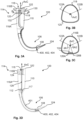
- the blade unit 100 in the illustrated example, comprises a handle portion 110 to form a handle portion of the laryngoscope.
- the handle portion may be omitted from the blade unit 100 and a handle portion may instead be provided by the control unit 200 couplable to the blade unit 100.
- the handle portion 110 may comprise different textures to provide for an enhanced grip.
- the handle portion 110 may comprise sunken parts.
- the sunken parts of the handle portion 110 may comprise a rougher texture than the remainder of the handle portion 110.
- the rough texture may enhance the grip.
- the smoother parts of the handle portion may facilitate production as it may, in case of, e.g. injection molding, facilitate removal of the halves from the mold.
- the blade unit 100 e.g. one or more shell parts of the blade unit 100, may be injection molded.
- the blade unit 100 may comprise two halves, which may be injection molded. The two halves may be joined by means of ultrasonic welding and/or by adhesive.
- the control unit 200 comprises a control unit display element 210 with a control unit display 212 (see Figs. 1A/1B ).
- the control unit display element 210 is attached to the attachment part 204 of the second body portion 202B.
- the control unit display element 210 may be hingedly attached to the attachment part 204.
- the control unit display element 210 and the attachment part 204 may be connected by a hinge 214.
- the control unit display element 210 may be rotatable about a hinge axis AxH relative to the second body portion 202B, such as relative to the attachment part 204 of the second body portion 202B.
- the control unit 200' comprises a connector cable 216 adapted to connect the control unit 200' to a monitor device 300 (see Fig. 2 ).
- the connector cable 216 is attached to the attachment part 204 of the second body portion 202B.
- the second body portion 202B of the control unit 200, 200' comprises a control button 206 with a button surface 208.
- the control unit 200, 200' may be adapted to execute functions, such as storing still images and/or video, in response to receipt of various user inputs, e.g. short press or long press, of the control button 206.
- the control button may further comprise a control button light indicator 209.
- the control button light indicator 209 may be used to indicate various information associated with the control unit 200, 200', such as, for example, whether a blade unit 100 is coupled or not.
- the control unit 200 comprises a battery pack 230.
- the battery pack may comprise a battery 222, such as a rechargeable battery.
- the battery pack 230 may be replaceable.
- the battery pack 230 being replaceable provides for a backup solution in case of low power, in that a spare battery pack may be kept with the control unit 200.
- the battery 222 may be adapted to power the control unit 200.
- the battery 222 may further be adapted to power the image sensor 402 and/or the light emitter 404.
- the battery 222 may be adapted to power electronics of the blade unit 100, such as the image sensor 402 and the light emitter 404 of the blade unit 100, when the control unit 200 and the blade unit is coupled.
- the control unit 200' may omit a battery and/or battery pack, as it may receive power from the monitor device.
- the control unit 200' may similarly comprise a battery pack 230 and/or a battery 222.
- the control unit 200, 200' comprises an electrical control unit connector 220 at a distal end 203 of the first body portion 202A.
- the electrical control unit connector 220 is adapted to electrically connect the control unit 200, 200' to the camera unit 400, image sensor 402 and/or light emitter 404 of the blade unit 100.
- the electrical control unit connector 220 may be used for connecting a data transfer cable to the control unit 200, 200', e.g. to allow transfer of data from internal memory of the control unit 200, 200' to an external device, such as a laptop, a smart phone, a tablet, etc.
- the control unit 200 comprises a power button 224.
- the control unit 200 may comprise a battery light indicator, which may form part of the power button or be separate thereto.
- the battery light indicator may be provided by the display of the control unit display element 210 or the power button 224 may comprise the battery light indicator.
- the power button 224 and/or the battery light indicator may be arranged on the control unit display element 210, e.g. on a side of the control unit display element 210, as illustrated.
- the power button 224 and the battery light indicator may be arranged on the same side of the control unit display element 210, e.g. next to each other.
- the power button 224 may be used to turn on/off the power of the control unit 200 and/or to check a current status of the battery 222.
- the control unit 200' may omit a power button 224, as it may receive power from the monitor device, and hence may be turned on whenever it is connected to the monitor device. However, in some examples, the control unit 200' may similarly comprise a power button 224. Particularly, if the control unit 200' comprises a battery pack 230 and/or a battery 222, it may be relevant to provide the control unit 200' also with the disclosed power button 224.
- the control unit 200 may comprise a light sensor 260.
- the control unit 200 may be adapted to automatically adjust brightness of the control unit display 212 in accordance with the amount of ambient light. For example, if the control unit 200 is used in a setting with much ambient light, e.g. outside, the brightness of the control unit display 212 may be high, whereas in a setting with little ambient light, e.g. inside, such as in a dark room, the brightness of the control unit display 212 may be low. An icon or alert on the screen may be shown when the screen brightness is adjusted and to what level it has been adjusted to. Additionally, or alternatively, the user may have a possibility, e.g. via a touch interface on the control unit display 212 to manually adjust the brightness of the control unit display 212. For example, the user may turn up brightness by swiping upwards on the control unit display 212 and turn down brightness by swiping downwards on the control unit display 212.
- the blade unit 100 comprises a blade coupling portion 114 adapted to couple the blade unit 100 to the control unit 200, 200' to form the laryngoscope 6, 6' (see Figs. 6 and 7 ).
- the blade coupling portion 114 comprises a channel 116 extending along a channel axis AxC to receive the first body portion 202A of the control unit 200, 200' (see Figs. 4A, 4B, 5A and 5B ).
- the first body portion 202A of the control unit 200, 200' may extend along a first body portion axis AxB, as illustrated in Figs. 4A, 4B, 5A and 5B .
- the first body portion axis AxB may be substantially parallel to the channel axis AxC.
- the channel 116 is formed of a first channel part 116A and a second channel part 116B.
- the second channel part 116B is between the proximal end 102 of the blade unit 100 and the first channel part 116A.
- the second channel part has a dimension to fit a human finger, such as a minimum distance between the proximal end 102 of the blade unit and the first channel part 116A of approx. 1 cm.
- the first channel part 116A and the second channel part 116B are connected along a connected portion 118 and separated along a slit portion 120.
- Fig. 3B schematically illustrates a cross-sectional view of the exemplary coupling portion 114 along the line B-B in Fig. 3A .
- the connected portion extends from a first angular position 122A to a second angular position 122B about the channel axis AxC.
- the slit portion 120 extends from the second angular position 122B to the first angular position 122A about the channel axis AxC.
- the slit portion 120 may be longer than the connected portion 118, i.e.
- Fig. 3C schematically illustrates a cross-sectional view of the exemplary coupling portion 114 along the line C-C in Fig. 3A .
- the second channel part 116B comprises a retention element 124 between a first retention element angular position 126A and a second retention element angular position 126B about the channel axis AxC.
- the retention element 124 may be a protrusion, as illustrated. Alternatively, the retention element may be a recess.
- the retention element 124 is provided on an inner surface of the second channel part 116B and facing the channel axis AxC.
- the first body portion 202A of the control unit 200, 200' may comprise one or more cooperating retention elements 248 (see Figs. 4A, 4B, 5A and 5B ).
- the retention element 124 is adapted to engage with the one or more cooperating retention elements 248 of the first body portion 202A of the control unit 200, 200'.
- the first retention element angular position 126A and the second retention element angular position 126B are within the slit portion 120.
- An angular distance dA1 between the first retention element angular position 126A and the first angular position 122A is at least 45 degrees, such as at least 70 degrees.
- An angular distance dA2 between the second retention element angular position 126B and the second angular position 122B is at least 45 degrees, such as at least 70 degrees.
- the angular distance dA1 between the first retention element angular position 126A and the first angular position 122A and the angular distance dA2 between the second retention element angular position 126B and the second angular position 122B may be substantially the same.
- the slit portion 120 between the first channel part 116A and the second channel part 116B provides a flexibility of the second channel part 116B, allowing the wall of the second channel part 116B comprising the retention element 124 to move radially outwards, i.e. away from the channel axis AxC, thereby allowing the retention element 124 to pass over the cooperating retention element 248 of the control unit 200, 200'.
- the retention element 124 may be forced radially outwards, i.e. away from the channel axis, by the user pushing radially inwards on the sides of the second channel part 116B, e.g. at a pinch point indicator 130.
- the first body portion 202A of the control unit 200, 200' may be thinner along the part being located in the second channel part 116A, when being received in the channel 116, such as to allow the sides of the second channel part 116B to be deflected inwards, when disengaging the blade unit and the control unit 200, 200'.
- the first body portion 202A may have a first width w1 at a first position between a proximal end 252 of the first body portion 202A adjoining the second body portion 202B and an intermediate position 254 along the first body portion axis AxB.
- the first body portion may have a second width w2 greater than the first width w1.
- the second width w2 is at a second position between the intermediate position 254 and a distal position 256 along the first body portion axis AxB.
- the second width may decrease towards the distal position 256.
- the width of the first body portion 202A may decrease towards the distal portion 256 and/or towards the distal end 203.
- the width of the first body portion 202A may decrease to facilitate easier insertion of the first body portion 202A in the channel 116 of the blade unit 100.
- the exemplary shape of the channel 116 and the first body portion 202A may provide for a shape of the handle portion 110, which conforms to the palm of a hand.
- the blade unit 100 comprises a camera unit 400 comprising an image sensor 402 and optionally a light emitter 404.
- a camera unit 400 as described in relation to Figs. 11-12 may be arranged in the distal part 106.
- the blade unit 100 comprises an electrical blade connector 112.
- the electrical blade connector 112 may comprise one or more terminals electrically connected to the image sensor 402 and/or the light emitter 404, e.g. via an electrical camera connector 401 extending from the electrical blade connector 112 to the camera unit 400 in the distal part 106.
- the electrical blade connector 112 is adapted to electrically connect the image sensor 402 and/or the light emitter 404 with the control unit 200, 200'.
- Fig. 6 schematically illustrates an exemplary laryngoscope 6 formed collectively of the control unit 200, as described in more detail in relation to Figs. 4A and 4B , and the blade unit 100, as described in more detail in relation to Fig. 3A .
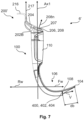
- Fig. 7 schematically illustrates another exemplary laryngoscope 6' formed collectively of the control unit 200' as described in more detail in relation to Figs. 5A and 5B , and the blade unit 100, as described in more detail in relation to Fig. 3A .
- the laryngoscopes 6 and 6' comprises identical or very similar features.
- Figs. 6 and 7 will be described together.
- the control unit 200, 200' and the blade unit 100 collectively form the laryngoscope 6, 6' with the handle portion 110 extending along a first axis Ax1.
- a forward direction Fw of the laryngoscope 6, 6' is perpendicular to the first axis Ax1 in a direction towards the distal end 104 of the blade unit 100.
- a rearward direction Rw of the laryngoscope 6, 6' is opposite the forward direction Fw.
- the forward direction Fw and the rearward direction Rw are extending in a laryngoscope mid-plane defined by the first axis and the distal end 104 of the blade unit 100. In Fig. 6 the laryngoscope mid-plane is in the plane of the paper.
- the button surface 208 of the control button 206 has a button surface normal 208n.
- the button surface 208 may be curved in various directions.
- the button surface normal 208n may be the normal at a center of the button surface 208.
- the button may be tilted in a forward direction, e.g. to be more easily accessible with the index finger.
- an angle between the button surface normal 208n and the forward direction Fw may be less than 90 degrees, such as less than 80 degrees.
- An angle between the button surface normal 208n and the first axis Ax1 may be between 0-180 degrees, such as between 1-179 degrees.
- the angle between the button surface normal 208n and the first axis Ax1 may be less than 90 degrees.
- the camera unit 400, the image sensor 402 and/or the light emitter 404 may be arranged at the distal end 203 of the first body portion 202A.
- the blade unit 100' may be devoid of a camera unit, image sensor and/or light emitter, and instead comprise a channel to receive the extension portion 258 of the first body portion 202A of the control unit 200".
- the camera unit 400, image sensor 402 and/or light emitter 404 may be arranged at the distal part 106 of the blade unit 100', with a viewing direction at least partly towards the distal end 104 of the blade unit 100'.
- Such embodiment may be advantageous in that the blade unit 100' comprises less electronics, and therefore may be cheaper.
- the control unit 200 such as a control unit processing unit 218 of the control unit 200, is adapted to receive image data from the image sensor 402 as the image data is being generated by the image sensor 402. To achieve this, the control unit 200 is couplable to the blade unit 100.
- the control unit 200 comprises an electrical control unit connector 220 with a plurality of terminals 221, and the blade unit 100 comprises an electrical blade connector 112 with a plurality of terminals 113.
- the electrical control unit connector 220 is couplable to the electrical blade connector 112, to electrically connect the terminals 221 of the electrical control unit connector 220 and the terminals 113 of the electrical blade connector 112.
- the control unit 200 comprises a battery 222.
- the battery 222 may be provided as part of a battery pack, e.g. comprising mechanical elements and/or additional circuitry, e.g. for charging and/or determining level of charge of the battery 222.
- the battery 222 may be a rechargeable battery.
- the battery 222 may be adapted to power the control unit 200, such as electronic components of the control unit 200.
- the battery 222 may further be adapted to power the image sensor 402 and/or the light emitter 404.
- the battery 222 may be adapted to power electronics of the blade unit 100, such as the image sensor 402 and the light emitter 404 of the blade unit 100, when the control unit 200 and the blade unit is coupled.
- the battery 222 may be adapted to power electronics of the blade unit 100, such as the image sensor 402 and the light emitter 404 of the blade unit 100, via the terminals 113, 221 of the electrical connectors 112, 220.
- the control unit 200 may comprise a control button 206, such as exemplified in Figs. 4A-4B .
- the control unit 200 may be adapted to execute functions, such as storing still images and/or video, in response to receipt of various user inputs, e.g. short press or long press, of the control button 206.
- the control button 206 may be coupled to the control unit processing unit 218, and the control unit processing unit 218 may be used to interpret user input received by the control button 206 and/or to execute actions in accordance with the received user input.
- the control unit 200 such as the control processing unit 218, may be adapted to distinguish between various types of user input at the control button 206.
- control unit 200 such as the control processing unit 218, may differentiate between a short press, e.g. having a duration shorter than a threshold amount of time (e.g. 1 second) and a long press, e.g. having a duration longer than the threshold amount of time.
- a short press e.g. having a duration shorter than a threshold amount of time (e.g. 1 second)
- a long press e.g. having a duration longer than the threshold amount of time.
- the control unit 200 may be adapted to detect a third user input corresponding to the second press of the control button 206 (e.g. a long press), and in accordance with detection of the third user input cause ending the recording of the first video file.
- the first video file may correspond to the image data received between detection of the second user input and the third user input.
- a short press may be used to capture a still image
- a long press may be used to start and stop recording of a video.
- the control unit 200 such as the control unit processing unit 218, may be adapted to automatically stop a video recording if it is detected that the remaining memory is below a certain threshold. Thereby, a complete video file may be stored in the memory 219, before the memory 219 is completely full, decreasing the risk of storing potentially corrupt files.
- the user interface on the control unit display 212 may show remaining memory, in terms of how many minutes of video recording can be stored.
- the electrical control unit connector 220 may also be used for connecting a data transfer cable to the control unit 200, e.g. to allow transfer of data, e.g. image and/or video data, from the memory 219 of the control unit 200 to an external device, such as a laptop, a smart phone, a tablet, etc.
- the data transfer cable may have a plug at one end resembling the electrical blade connector 112 and a USB plug at the other end, thereby facilitating connection between the control unit 200 and an external device with a USB port.
- the control unit 200 When being connected to an external device the control unit 200 may act like a flash drive.
- the control unit display may display "file transfer" to indicate that files are being transferred to the external device.
- the control unit 200 may comprise a control button light indicator 209, which, as mentioned in relation to Figs. 4A and 4B may be integrated with the control button 206.
- the control button light indicator 209 may be used to indicate various information associated with the control unit 200, such as, for example, whether a blade unit 100 is coupled or not.
- the control unit 200 such as the control unit processing unit 218, may detect coupling with the blade unit 100, and in accordance with detection of coupling between the blade unit 100 and the control unit 200 provide a first visual indication with the control button light indicator 209.
- the control unit 200 such as the control unit processing unit 218, may provide a second visual indication with the control button light indicator.
- Fig. 10 is a block diagram schematically illustrating an exemplary visualization system 2 with a laryngoscope assembly 4' and a monitor device 300.
- the laryngoscope assembly 4' comprises a control unit 200' and a blade unit 100.
- the laryngoscope assembly 4' may be the laryngoscope assembly 4' as exemplary illustrated, e.g., in Figs. 2 and 7 .
- the control unit 200' may be connectable to a monitor device.
- the blade unit 100 may be similar to the blade unit 100 as illustrated and explained in relation to Fig. 9 .
- the monitor device 300 may be the monitor device 300 as illustrated in Fig. 2 .
- the monitor device 300 may comprise a monitor display 302, a monitor processing unit 304 and a monitor connector 306.
- the control unit 200' may comprise a connector cable 216.
- the connector cable 216 may be adapted to connect the control unit 200' to the monitor device 300.
- the connector cable 216 may be connectable to a monitor connector 306 of the monitor device 300.
- the connector cable 216 may have a plug and the monitor connector 306 may have a corresponding socket for receiving the plug of the connector cable 216.
- the control unit 200' may comprise a cable interface 215 connecting the connector cable 216 to the internal electronics of the control unit 200'.
- the connector cable 216 may be decouplable from the remainder of the control unit 200' at the cable interface 215 or it may be fixedly attached to the remainder of the control unit 200'.
- the control unit 200' may omit a battery, and may be powered by the monitor device 300, e.g. through the connector cable 216.
- the monitor device 300 may comprise a battery and/or a power supply to power both the monitor device 300 and the control unit 200'.
- the control unit 200' may comprises a battery 222 as explained in relation to Fig. 9 .
- the control unit 200' may be adapted to power the image sensor 402 and/or the light emitter 404.
- the control unit 200' may be adapted to power electronics of the blade unit 100, such as the image sensor 402 and the light emitter 404 of the blade unit 100, when the control unit 200' and the blade unit 100 is coupled.
- the control unit 200 may be adapted to power electronics of the blade unit 100, such as the image sensor 402 and the light emitter 404 of the blade unit 100, via the terminals 113, 221 of the electrical connectors 112, 220.
- the control unit 200' may comprise a control button 206, such as exemplified in Figs. 5A-5B .
- the control unit 200' may be adapted to cause functions, such as storing still images and/or video, in response to receipt of various user inputs, e.g. short press or long press, of the control button 206.
- the control button 206 may be coupled to the control unit processing unit 218, and function as described in relation to Fig. 9 .
- the monitor device 300 such as the monitor processing unit 304, may be adapted to detect a first user input corresponding to a first press of the control button 206 (e.g. a short press), and in accordance with detection of the first user input cause recording (e.g. in memory 305 of the monitor device 300) of a first image file corresponding to the image data received when the first user input was detected.
- the monitor device 300 such as the monitor processing unit 304, may be adapted to detect a second user input corresponding to a second press of the control button 206 (e.g. a long press), and in accordance with detection of the second user input cause initiating a recording (e.g.
- the monitor device 300 may cause the monitor device display 302 to briefly show a colored border, e.g. around the live image, to indicate to the user that a video and/or a still image has been recorded.
- the border may be continuously shown while recording, and disappear when recording is stopped.
- the monitor device 300 such as the monitor processing unit 304, may be adapted to start recording of a video file in response to detection of the control unit 200' being coupled to a blade unit. Thereby, the entire procedure, from assembling the laryngoscope may be recorded.
- the monitor device 300 such as the monitor processing unit 304 may be adapted to start recording in response to connecting the control unit 200' to the monitor device 300.
- the first visual indication may correspond to the control button light indicator 209 being steadily lit, and the second visual indication may correspond to the control button light indicator 209 blinking.
- the first visual indication may be with a first color and the second visual indication may be with a second (different) color.
- Fig. 10 applies mutatis mutandis to a laryngoscope assembly comprising the control unit 200' being connectable to the monitor device modified to comprise the extension portion 258, as described with respect to Fig. 8 .
- the camera unit 400 may form part of the control unit 200', and at least the electronic elements of the electrical connectors 220, 112 may be omitted.
- the blade unit 100 may be devoid of electronic elements.
- Fig. 11 schematically illustrates an exemplary camera unit 400, which may be provided at the distal part 106 of the blade unit 100, as described in relation to Fig. 3A or at a distal end 203 of the control unit 200", as described in relation to Fig. 8 .
- the camera unit 400 comprises an image sensor 402 and a light emitter 404 (see Figs. 12A and 12B ).
- the camera unit 400 comprises an electrical camera connector 401, which, for example, may electrically connect the camera unit 400, such as the image sensor 402 and/or the light emitter 404 thereof, to the electrical blade connector 112 of the blade unit 100, and/or to the control processing unit 218 of the control unit 200 (see, e.g., Figs. 9 and 10 and the related description).
- the electrical camera connector 401 may be a flexible printed circuit. Alternatively, it may be provided by a collection of wires or other techniques known in the art.
- Fig. 12A schematically illustrates a cross-sectional view of the camera unit 400 of Fig. 11.
- Fig. 12B schematically illustrates a cross-sectional view of an exemplary camera unit 400', which resembles the camera unit 400, although having the image sensor 402 and the light emitter 404 being (more) offset along the viewing direction.
- Figs. 11, 12A and 12B will be described together in the following.
- the camera unit 400 comprises a camera unit housing 410.
- the camera unit housing comprises a first side wall 411 and a second side wall 412.
- the camera unit housing 410 further comprises a third side wall 413 extending between the first side wall 411 and the second side wall 412.
- the camera unit housing 410 further comprises a fourth side wall 414 extending between the first side wall 411 and the second side wall 412.
- the camera unit housing 410 further comprises a separating wall 415 extending between the first side wall 411 and the second side wall 412.
- the separating wall 415 is further arranged between the third side wall 413 and the fourth side wall 414.
- the separating wall 415 is acting to prevent or reduce light from the light emitter 420 travelling directly to the image sensor 402, which may distort the images generated by the image sensor 402.
- the separating wall 415 is preferably opaque to light, at least within the visible spectrum of light and optionally ultraviolet and/or infrared light.
- a first housing compartment 416A of the camera unit housing 410 is defined by the first side wall 411, the second side wall 412, the third side wall 413 and the separating wall 415.
- the image sensor 402 is accommodated in the first housing compartment 416A.
- the image sensor is adapted to generate image data indicative of a view along a viewing direction V from a front surface 418 of the image sensor 402.
- a second housing compartment 416B of the camera unit housing 410 is defined by the first side wall 411, the second side wall 412, the fourth side wall 414 and the separating wall 415.
- the light emitter 404 is accommodated in the second housing compartment 416B.
- the light emitter 404 is adapted to emit light along the viewing direction V from a front surface 420 of the light emitter 404.
- the separating wall 415 may have a length 415L along the viewing direction V, e.g., of more than 1.5 mm, such as more than 2 mm.
- the viewing direction V corresponds to the viewing direction V of Figs. 6 and 7 , when the camera unit 400 is arranged as intended in the blade unit 100, i.e., being from the distal part 106 of the blade unit in a direction at least partly towards the distal end 104 of the blade unit 100.
- the camera unit housing 400 may further comprise a front side wall 422 extending between the first side wall 411 and the second side wall 412 and between the third side wall 413 and the fourth side wall 414.
- the front side wall has a first window 424A and a second window 424B.
- the separating wall 415 adjoins the front side wall 422 between the first window 424A and the second window 424B.
- the first window 424A provides an optical connection between the first housing compartment 416A through the front side wall 422.
- the second window 424B provides an optical connection between the second housing compartment 416B through the front side wall 422.
- the image sensor 402 may be arranged with a distance d1 between the front surface 418 of the image sensor 402 and the first window 424A.
- the distance may reduce undesired reflections possibly distorting the images generated by the image sensor 402.
- the distance d1 between the front surface 418 of the image sensor 402 and the first window 424A may be between 0.1 mm and 0.5 mm, such as between 0.2 mm and 0.4 mm.
- the light emitter 404 may be arranged with a distance d2 between the front surface 420 of the light emitter 404 and the second window 424B.
- the distance d2 between the front surface 420 of the light emitter 404 and the second window 424B may be between 0.1 mm and 0.5 mm, such as between 0.2 mm and 0.4 mm.
- the distance d1 between the front surface 418 of the image sensor 402 and the first window 424A may be smaller than the distance d2 between the front surface 420 of the light emitter 404 and the second window 424B.
- the image sensor 402 and the light emitter 404 may be arranged with an offset distance df along the viewing direction V, e.g. as illustrated in Fig. 12B , between the front surface 418 of the image sensor 402 and the front surface 420 of the light emitter 404.
- the light emitter 404 may be arranged behind the image sensor 402.
- the offset distance df may be between 0.1 mm and 1.5 mm, such as between 0.5 mm and 1 mm.
- the image sensor 402 and light emitter 404 may be arranged flush, as illustrated in Fig. 12A . In the example of Fig.
- the front of the windows 424A, 424B may be flush like in Fig. 12A while the mage sensor 402 and the light emitter 404 are arranged with the offset distance df.
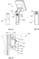
- Fig. 13 schematically illustrates the exemplary control unit 200, and more particularly illustrates that the control unit 200 may utilize a replaceable battery pack 230 adapted to power the control unit 200.
- the control unit 200 comprises a battery receiver 228 adapted to receive the replaceable battery pack 230.
- Fig. 14 schematically illustrates the battery pack 230 from the side to be received by the battery receiver 228.
- the battery receiver 228 comprises a battery connector 232 with a plurality of battery connector terminals 234.
- the battery connector terminals 234 are adapted to cooperate with corresponding connection terminals 236 of the replaceable battery pack 230.
- the battery pack 230 may comprise a rechargeable battery.
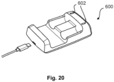
- the battery pack 230 may be removed from the control unit 200 and be placed in a charger adapted to charge the battery.
- the battery pack 230 may be dimension such that it is retained in the battery receiver 228 by friction. Hence, mechanical locking between the battery pack 230 and the battery receiver 228 may be omitted. This means that the battery pack 230 can easily be attached to the battery receiver 228 by just pushing the battery pack 230 into place.
- the battery pack 230 may provide parts which are slightly wider than the first body portion 202A, and which thereby protrudes slightly from the sides of the first body portion 202A. Thereby, removal of the battery pack 230 may be made easier.
- the battery receiver 228 comprises an outer connector seal 238 encircling the battery connector 232.
- the outer connector seal 238 is adapted to contact a corresponding surface 240 of the replaceable battery pack 230, when the replaceable battery pack 230 is received in the battery receiver 228.
- the corresponding surface 240 of the replaceable battery pack 230 is a surface encircling the connection terminals 236 of the replaceable battery pack 230. Thereby, water or other liquid is restricted from entering the electrical interface between the battery pack 230 and the battery receiver 228. Hence, risk of liquid interfering the electrical connection is reduced.
- the replaceable battery pack 230 may be devoid of an outer sealing element adapted to contact a surface of the control unit 200, such as a surface of the battery receiver 228.
- the corresponding surface 240 of the replaceable battery pack 230 contacting the outer connector seal 238 may merely be a part of the outer surface of the battery pack, e.g. as indicated by the dotted line in Fig. 14 , and may not be visually distinct from the remainder of such surface.
- the battery receiver 228 may form part of the first body portion 202A of the control unit 200, as illustrated.
- the first body portion 202A may be adapted to be received and enclosed by the blade unit, such as the handle portion 110 of the blade unit 100 (see, e.g. Fig. 6 ).
- the battery pack 230 and the battery receiver 228 may be fully enclosed by the blade unit 100, i.e. the battery pack 230 does not form an outer surface of the assembled laryngoscope, and the battery pack 230 is kept away from contact with the patient.
- the battery pack 230 does not form part of the outer surface of the assembled laryngoscope, the battery pack is protected, which is particularly advantageous for a rechargeable battery pack 230.
- Fig. 15 schematically illustrates an exemplary cross-sectional view of a battery connector 232, such as the battery connector 232 of the battery receiver 228 as also described in relation to Fig. 13 .
- the battery receiver 228 comprises a battery connector 232 with a plurality of battery connector terminals 234 adapted to cooperate with corresponding connection terminals 236 of the replaceable battery pack 230 (see Fig. 14 ).
- the battery receiver 228 comprises an outer connector seal 238 encircling the battery connector 232 adapted to contact a corresponding surface 240 of the replaceable battery pack 230, when the replaceable battery pack 230 is received in the battery receiver 228.
- the control unit 200 may comprise an internal sealing 242 encircling the battery connector 232.
- the internal sealing 242 prevents liquid from entering from the battery receiver 228 and into an internal space of the control unit 200 when the replaceable battery pack 230 is not received in the battery receiver 228.
- the control unit 200 may further comprise a battery connector circuitry 244, e.g. a printed circuit board or other electronic circuitry known in the art, used to couple the battery connector terminals 234 to other relevant electronic components of the control unit 200, and to communicate with electronic components, such as a battery fuel gauge, of the battery pack 230.
- the battery connector 232 is attached to a first side of the battery connector circuity 244.
- the internal sealing 242 is arranged between the battery connector circuitry 244 and a shell element 246 forming part of the battery receiver 228. Thereby, water or other liquid is restricted from entering into the internal compartments of the control unit 200 at the battery connector 232, even when the battery pack 230 is not received. Hence, risk of liquid interfering with and potentially damaging the electronic components inside the control unit 200 is reduced, also in cases where the battery pack 230 is not received in the battery receiver 228.
- control unit 200' e.g., of Figs. 5A and 5B or the control unit 200", e.g., of Fig. 8
- the battery may be provided in a battery pack, such as the battery pack 230 as described, and the control unit 200', 200" may comprise a battery receiver, such as the battery receiver 228 as described above.
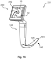
- Fig. 16 schematically illustrates an exemplary laryngoscope system 2.
- the illustrated laryngoscope system 2 comprises a laryngoscope 6, such as the laryngoscope 6, as also described in relation to, e.g., Figs. 1A, 1B and Fig. 6 .
- a laryngoscope 6 such as the laryngoscope 6, as also described in relation to, e.g., Figs. 1A, 1B and Fig. 6 .
- the functionality could be similarly implemented on another or complimentary laryngoscope system, e.g., wherein the laryngoscope is coupled to a monitor device with a display, such as illustrated in Fig. 2 .
- the laryngoscope system 2 comprises a blade unit 100, as also explained in relation to previous figures, extending from a proximal end 102 to a distal end 104, and having a distal part 106 extending to the distal end 104.
- the distal part 106 comprises a first surface 108.
- the distal part 106 is adapted to be inserted into a patient's oral cavity with the first surface 108 facing the patient's tongue.
- the laryngoscope system 2 further comprises an image sensor adapted to generate image data indicative of a view in a viewing direction from the distal part 106 of the blade unit 100 in a direction at least partly towards the distal end 104.
- the image sensor may be provided either as part of the blade unit 100 as described in relation to Figs. 3A-3D , or as part of the control unit, as described in relation to Fig. 8 .
- the laryngoscope system 2 comprises a display 212, which, as illustrated may be a display 212 forming part of the control unit 200. However, the display may alternatively be a display of a monitor device to which the laryngoscope 6 is connected.
- the laryngoscope system 2 such as the control unit 200 (e.g. the control processing unit 212 of the control unit 200, cf. Fig. 9 ), is adapted to display a live representation 10 of the image data with the display 212.
- the laryngoscope system 2, such as the control unit 200 (e.g. the control processing unit 212), may further be adapted to detect a trigger-event, and in response to detection of the trigger event: start a timer function, and display, concurrently with the live representation 10, a value of the timer function 12 with the display 212.
- the timer function may be a countdown decreasing towards zero. Such countdown may start from a pre-defined amount of time, e.g. according to a guideline's predefined amount of time before reverting to alternative methods.
- the pre-defined amount of time may, for example, be 30 seconds.
- the timer function may be a timer starting from zero and counting upwards.
- the laryngoscope system 2 may detect coupling between the control unit 200 and the blade unit 100, and the trigger event may correspond to coupling of the blade unit 100 and the control unit 200.
- the timer function may start once the operator couples the blade unit 100 and the control unit 200.
- the trigger event may correspond to a user input, e.g. a press of a button or a touch sensitive display of the control unit 200.
- the laryngoscope system 2 such as the control unit 200 (e.g. the control processing unit 212 of the control unit 200, cf. Fig. 9 ), may detect, e.g. by image analysis of the image data, insertion of the distal part of the blade unit into a patient's oral cavity.
- the trigger event may correspond to insertion of the distal part of the blade unit into a patient's oral cavity, e.g. as detected by image analysis of the image data.
- the laryngoscope system may display the value of the timer function 12 having a first visual characteristic, and in accordance with the value of the timer function being within the low-threshold time range, the laryngoscope system may display the value of the timer function 12 having a second visual characteristic different from the first visual characteristic.
- the second visual characteristic may be a different color, e.g. orange, and/or the second visual characteristic may be blinking.
- Figs. 17A and 17B show from the side and the front, respectively, an exemplary control unit 200, such as the control unit 200 as described in relation to previous figures (e.g. in Figs. 4A and 4B ).
- control unit display element 210 may be positioned more towards the user, i.e. in the rearward direction Rw relative to the first axis Ax1 and/or the body portion axis AxB following the terminology as explained in relation to Figs. 4A, 4B and 6 .
- the inventors have found, and verified by user tests, that having the display shifted towards the user facilitates a superior weight distribution of the control unit 200, on its own as well as when being coupled with the blade unit. Thereby, the control unit 200 may facilitate better handling, and consequently improve intubation.
- the control unit 200 has a first control unit distance dd1 between the control unit display 212 and the hinge axis AxH.
- the first control unit distance dd1 may be between 20-30 mm, such as between 23-25 mm.
- the control unit display element 210 has a second control unit distance dd2 between a rearward surface of the control unit display element 210 and a forward surface of the control unit display element 210, e.g. the control unit display 212.
- the second control unit distance dd2 may be between 10-20 mm, such as between 15-18 mm.
- the hinge axis AxH may be positioned with a third control unit distance dd3 from the first axis Ax1 and/or the body portion axis AxB.
- the third control unit distance dd3 may be between 20-30 mm, such as between 25-29 mm.
- the hinge axis AxH may be positioned, along the first axis Ax1 and/or body portion axis AxB, between a top edge and a bottom edge of the control unit display element 210.
- the hinge axis AxH may be positioned with a fourth control unit distance dd4 from the bottom edge of the control unit display element 210.
- the fourth control unit distance dd4 may be between 10-15 mm, such as between 12-13 mm.
- An upper surface of the second body portion 202B may be inclined and the button surface 208 of the control button 206 may be provided below the hinge axis AxH, along the first axis Ax1 and/or the body portion axis AxB, by a fifth control unit distance dd5.
- the fifth control unit distance dd5 may be between 1-10 mm, such as between 4-6 mm.
- the button surface 208 and/or the upper surface of the second body portion 202B may form upper body portion angle dAd1 with respect to a line perpendicular to the first axis Ax1 and/or the body portion axis AxB.
- the upper body portion angle dAd1 may be between 20-35 degrees, such as between 25-30 degrees.
- the control unit display element 210 may have a sixth control unit distance dd6, i.e. a height, between the bottom edge and the top edge of the control unit display element 210.
- the sixth control unit distance dd6 may be between 60-100 mm, such as between 75-85 mm.
- the control unit 200 may have a seventh control unit distance dd7, along the first axis Ax1 and/or the body portion axis AxB, between the distal end 203 of the first body portion 202A and the hinge axis AxH.
- the seventh control unit distance dd7 may be between 90-110 mm, such as between 95-105 mm.
- the control unit 200 may have a distance between the button surface 208 and the distal end 203 of the first body portion 202A, which may be between 85-105 mm, such as between 90-100 mm.
- the first body portion 202A may have an eighth control unit distance dd8 between a front surface facing the forward direction Fw and a rear surface facing the rearward direction Rw.
- the front surface may be a surface of a replaceable battery pack.
- the eighth control unit distance dd8 may be perpendicular to the first axis Ax1 and/or the body portion axis AxB.
- the eighth control unit distance dd8 may be between 20-35 mm, such as between 25-30 mm.
- the control unit display element 210 may have a ninth control unit distance dd9 between a left edge and a right edge of the control unit display element 210.
- the ninth control unit distance dd9 may be between 75-100 mm, such as between 80-90 mm.
- the first body portion 202A may have a first width w1 at a first position and the first body portion may have a second width w2 at a second position.
- the second width w2 may be greater than the first width w1.
- the first width w1 may be between 25-35 mm, such as between 26-29 mm.
- the second width w2 may be between 25-35 mm, such as between 29-32 mm.
- the width of the first body portion 202A e.g. the second width w2, and/or the eighth control unit distance dd8 may decrease towards the distal end 203.
- the width of the first body portion 202A and/or the eighth control unit distance dd8 may decrease to facilitate easier insertion of the first body portion 202A in the channel of the blade unit.
- the inventors have found that the geometry and size of the exemplary control unit 200 are advantageous in terms of ergonomics and handling.
- Figs. 18A and 18B show an exemplary electrical control unit connector 220 of the control unit 200, 200'.
- the electrical control unit connector 220 is adapted to electrically connect the control unit 200, 200' to the camera unit 400, image sensor 402 and/or light emitter 404 of the blade unit 100, as explained previously.
- Fig. 18B shows a cut open view of the electrical control unit connector 220.
- the electrical control unit connector 220 may comprise an alignment feature 262, e.g. a wall, separating the electrical control unit connector 220 in two unequal parts 264, 266.
- a retention element 268, e.g. a spring may be provided in combination with the separating element 262.
- the blade unit 100 as illustrated in Fig.
- the electrical blade connector 112 is sectioned into two unequal parts corresponding to the parts 264, 266 of the electrical control unit connector 220. Furthermore, the electrical blade connector 112 of the blade unit 100 may comprise indents for cooperation with the retention element 268.
- the electrical control unit connector 220 may comprise one or more gaskets 270 surrounding the two parts 264, 266 and the terminals 221 of the electrical control unit connector 220.
- the connector itself i.e. the two parts 264, 266 may be liquid tight, e.g. by integrated metal plastic injection molding.
- the gasket 270 extends ensures that no liquid is able to enter the device between the electrical control unit connector 220 and the surrounding shell of the control unit.
- the gasket 270 is preferably made out of rubber, or another suitable flexible material.
- Fig. 19 schematically illustrates an exemplary carry case 500 for the exemplary control unit 200, as described in relation to previous figures.
- the carry case 500 comprises a top casing 502 and a bottom casing 504 hinged along a first side 506 and connectable with a latch 510 along an opposite second side 508.
- An insert 512 e.g. foam or silicone
- the carry case 500 also comprises a battery space 514, e.g. as an indent in the insert 512, as illustrated, for holding a spare battery pack.
- a battery space 514 e.g. as an indent in the insert 512, as illustrated, for holding a spare battery pack.
- an additional or alternative battery space may be provided in the top casing 502.
- the insert 512 and bottom casing 504 are adapted such that the control unit 200 is positioned allowing the battery light indicator 226 is positioned above the edge of the bottom casing 504. Thereby, the battery light indicator 226 is visibly accessible while the control unit 200 is positioned in the carry case 500. Thereby, the battery status may be checked without having to remove the control unit 200 from the carry case 500.
- the insert 512 may be removable from the bottom casing 504 to facilitate cleaning of the carry case 500, as well as to facilitate replacement of the insert 512 in case needed.
- foam may be so called skinned foam or closed cell foam such as to avoid collection of dirt in the foam.
- the bottom casing 504 may comprise one or more retention elements, e.g. protruding elements, such as pins or ridges to retain the insert 512 in the bottom casing.
- Fig. 20 schematically illustrates an exemplary battery charger 600 for a battery pack 230, as described in relation to the previous figures, e.g. Figs. 13-15 .
- the exemplary battery charger 600 has space for charging two battery packs simultaneously.
- the battery charger 600 may be connected to a power supply e.g. by a USB cable, such as a USB-C cable.
- the battery charger 600 comprises status indicators 602 adapted to show battery status, e.g. the state of charge, of the respective inserted battery pack.
- the status indicator 602 may light up in, e.g., either, orange or green signaling the state of charge. No light may indicate no charging.
- the status indicators 602 may be not visible when not lid.
- light guides may be provided underneath the surface of the battery charger 600 to transmit the light from an LED to the surface.
- the battery charger 600 is preferably provided without small spaces, to avoid collection of dirt, and to allow an enhanced level of cleanability.
Landscapes
- Health & Medical Sciences (AREA)
- Life Sciences & Earth Sciences (AREA)
- Surgery (AREA)
- Engineering & Computer Science (AREA)
- Medical Informatics (AREA)
- Molecular Biology (AREA)
- Pathology (AREA)
- Radiology & Medical Imaging (AREA)
- Nuclear Medicine, Radiotherapy & Molecular Imaging (AREA)
- Biophysics (AREA)
- Biomedical Technology (AREA)
- Heart & Thoracic Surgery (AREA)
- Physics & Mathematics (AREA)
- Optics & Photonics (AREA)
- Animal Behavior & Ethology (AREA)
- General Health & Medical Sciences (AREA)
- Public Health (AREA)
- Veterinary Medicine (AREA)
- Signal Processing (AREA)
- Mechanical Engineering (AREA)
- Otolaryngology (AREA)
- Physiology (AREA)
- Pulmonology (AREA)
- Endoscopes (AREA)
Priority Applications (4)
| Application Number | Priority Date | Filing Date | Title |
|---|---|---|---|
| EP22177866.5A EP4289331A1 (de) | 2022-06-08 | 2022-06-08 | Videolaryngoskop |
| PCT/EP2023/065172 WO2023237578A1 (en) | 2022-06-08 | 2023-06-07 | Video laryngoscope |
| US18/864,466 US20250295302A1 (en) | 2022-06-08 | 2023-06-07 | Video laryngoscope |
| US18/207,112 US20230397795A1 (en) | 2022-06-08 | 2023-06-07 | Video laryngoscope |
Applications Claiming Priority (1)
| Application Number | Priority Date | Filing Date | Title |
|---|---|---|---|
| EP22177866.5A EP4289331A1 (de) | 2022-06-08 | 2022-06-08 | Videolaryngoskop |
Publications (1)
| Publication Number | Publication Date |
|---|---|
| EP4289331A1 true EP4289331A1 (de) | 2023-12-13 |
Family
ID=81984593
Family Applications (1)
| Application Number | Title | Priority Date | Filing Date |
|---|---|---|---|
| EP22177866.5A Pending EP4289331A1 (de) | 2022-06-08 | 2022-06-08 | Videolaryngoskop |
Country Status (3)
| Country | Link |
|---|---|
| US (1) | US20250295302A1 (de) |
| EP (1) | EP4289331A1 (de) |
| WO (1) | WO2023237578A1 (de) |
Citations (3)
| Publication number | Priority date | Publication date | Assignee | Title |
|---|---|---|---|---|
| US20080300464A1 (en) * | 2007-05-30 | 2008-12-04 | Atul K. Dhingra | Laryngoscope with Timer |
| CN113545726A (zh) * | 2020-04-24 | 2021-10-26 | 柯惠有限合伙公司 | 显示装置、显示方法和医疗器械 |
| US20220110504A1 (en) * | 2020-10-14 | 2022-04-14 | Covidien Lp | Medical device imaging systems and methods |
Family Cites Families (8)
| Publication number | Priority date | Publication date | Assignee | Title |
|---|---|---|---|---|
| US6652453B2 (en) * | 1999-03-03 | 2003-11-25 | Vincent A. Smith | Portable video laryngoscope |
| WO2008019367A2 (en) * | 2006-08-07 | 2008-02-14 | Innovative Medical Devices, Inc. | System to aid in the positioning, confirmation and documentation of an endotracheal tube |
| GB0906688D0 (en) * | 2009-04-17 | 2009-06-03 | Indian Ocean Medical Inc | Laryngoscope |
| US9364140B2 (en) * | 2010-05-13 | 2016-06-14 | Covidien Lp | Video laryngoscope |
| WO2011141752A2 (en) * | 2010-05-13 | 2011-11-17 | Aircraft Medical Limited | Battery pack and electrical device with demountable battery pack |
| US9498112B1 (en) * | 2013-03-15 | 2016-11-22 | Brent Stewart | Laryngoscope |
| US11033180B2 (en) * | 2017-11-03 | 2021-06-15 | Aircraft Medical Ltd. | Video laryngoscope systems and methods |
| US20240212516A1 (en) * | 2022-12-23 | 2024-06-27 | Covidien Lp | Direct laryngoscope training mode for video laryngoscope |
-
2022
- 2022-06-08 EP EP22177866.5A patent/EP4289331A1/de active Pending
-
2023
- 2023-06-07 US US18/864,466 patent/US20250295302A1/en active Pending
- 2023-06-07 WO PCT/EP2023/065172 patent/WO2023237578A1/en not_active Ceased
Patent Citations (3)
| Publication number | Priority date | Publication date | Assignee | Title |
|---|---|---|---|---|
| US20080300464A1 (en) * | 2007-05-30 | 2008-12-04 | Atul K. Dhingra | Laryngoscope with Timer |
| CN113545726A (zh) * | 2020-04-24 | 2021-10-26 | 柯惠有限合伙公司 | 显示装置、显示方法和医疗器械 |
| US20220110504A1 (en) * | 2020-10-14 | 2022-04-14 | Covidien Lp | Medical device imaging systems and methods |
Also Published As
| Publication number | Publication date |
|---|---|
| US20250295302A1 (en) | 2025-09-25 |
| WO2023237578A1 (en) | 2023-12-14 |
Similar Documents
| Publication | Publication Date | Title |
|---|---|---|
| US20230397795A1 (en) | Video laryngoscope | |
| JP5795671B2 (ja) | 映像化装置 | |
| US7615006B2 (en) | Electronic endoscope battery section | |
| CN102469929B (zh) | 手持式无线内窥镜 | |
| CA2501871C (en) | Sealed probe chamber for thermometry apparatus | |
| EP4289335A1 (de) | Videolaryngoskop | |
| US20190053778A1 (en) | Auscultation device with modular chest piece and ecg module | |
| WO2012169491A1 (ja) | 挿入口装着器 | |
| EP4289331A1 (de) | Videolaryngoskop | |
| EP4289332A1 (de) | Videolaryngoskop | |
| EP4289330A1 (de) | Videolaryngoskop | |
| US20240374467A1 (en) | Penetration detecting cap for masturbation device | |
| JP3645224B2 (ja) | フード部材装着具 | |
| JP4607786B2 (ja) | 呼吸データ収集システム | |
| JP3816811B2 (ja) | 内視鏡装置 | |
| US20250113990A1 (en) | Video Laryngoscope | |
| US20240148240A1 (en) | Endoscope system and interface adapter | |
| JP2003334167A (ja) | 内視鏡 | |
| JP7166125B2 (ja) | 医療用電子機器 | |
| JP4102319B2 (ja) | 被検体検査装置 | |
| CN118177699A (zh) | 一种胶囊内窥镜、包装装置、胶囊内窥镜激活系统 | |
| WO2021165358A1 (en) | User interface for a medical visualisation system | |
| JP2006223472A (ja) | バッテリ装置および内視鏡装置 |
Legal Events
| Date | Code | Title | Description |
|---|---|---|---|
| PUAI | Public reference made under article 153(3) epc to a published international application that has entered the european phase |
Free format text: ORIGINAL CODE: 0009012 |
|
| STAA | Information on the status of an ep patent application or granted ep patent |
Free format text: STATUS: THE APPLICATION HAS BEEN PUBLISHED |
|
| AK | Designated contracting states |
Kind code of ref document: A1 Designated state(s): AL AT BE BG CH CY CZ DE DK EE ES FI FR GB GR HR HU IE IS IT LI LT LU LV MC MK MT NL NO PL PT RO RS SE SI SK SM TR |
|
| STAA | Information on the status of an ep patent application or granted ep patent |
Free format text: STATUS: REQUEST FOR EXAMINATION WAS MADE |
|
| 17P | Request for examination filed |
Effective date: 20240611 |
|
| RBV | Designated contracting states (corrected) |
Designated state(s): AL AT BE BG CH CY CZ DE DK EE ES FI FR GB GR HR HU IE IS IT LI LT LU LV MC MK MT NL NO PL PT RO RS SE SI SK SM TR |
|
| GRAP | Despatch of communication of intention to grant a patent |
Free format text: ORIGINAL CODE: EPIDOSNIGR1 |
|
| STAA | Information on the status of an ep patent application or granted ep patent |
Free format text: STATUS: GRANT OF PATENT IS INTENDED |