EP4289318A1 - Luftfriteuse mit transparentem fenster - Google Patents
Luftfriteuse mit transparentem fenster Download PDFInfo
- Publication number
- EP4289318A1 EP4289318A1 EP21924149.4A EP21924149A EP4289318A1 EP 4289318 A1 EP4289318 A1 EP 4289318A1 EP 21924149 A EP21924149 A EP 21924149A EP 4289318 A1 EP4289318 A1 EP 4289318A1
- Authority
- EP
- European Patent Office
- Prior art keywords
- door panel
- frying basket
- air fryer
- window
- transparent window
- Prior art date
- Legal status (The legal status is an assumption and is not a legal conclusion. Google has not performed a legal analysis and makes no representation as to the accuracy of the status listed.)
- Granted
Links
Images




Classifications
-
- A—HUMAN NECESSITIES
- A47—FURNITURE; DOMESTIC ARTICLES OR APPLIANCES; COFFEE MILLS; SPICE MILLS; SUCTION CLEANERS IN GENERAL
- A47J—KITCHEN EQUIPMENT; COFFEE MILLS; SPICE MILLS; APPARATUS FOR MAKING BEVERAGES
- A47J37/00—Baking; Roasting; Grilling; Frying
- A47J37/06—Roasters; Grills; Sandwich grills
- A47J37/0623—Small-size cooking ovens, i.e. defining an at least partially closed cooking cavity
- A47J37/0629—Small-size cooking ovens, i.e. defining an at least partially closed cooking cavity with electric heating elements
- A47J37/0641—Small-size cooking ovens, i.e. defining an at least partially closed cooking cavity with electric heating elements with forced air circulation, e.g. air fryers
Definitions
- the present disclosure relates to the field of air fryers, in particular to an air fryer with a transparent window.
- An air fryer is an electrical appliance that uses high-temperature air to fry and roast food.
- the existing air fryers are often equipped with a window structure.
- Some of the windows are set on the drawer-type frying basket, and some are set on the top of the body.
- the sealing of the window structure provided on the drawer-type frying basket is a problem, in which the window is easy not to be installed firmly, and therefore, the sealing is poor, which will cause the heat in the frying basket to leak.
- illumination lights are generally installed inside the air fryer with a window.
- the illumination light of most products is installed in places where the ambient temperature is relatively high, which will lead to a short lifespan of the illumination lights.
- the present disclosure provides an air fryer with a transparent window, which can realize the positioning and installation of the window member, at the same time, effectively prevent the heat in the frying basket from overflowing, reduce the ambient temperature at the installation position of the illumination light, and prolong the lifespan of the illumination light.
- An air fryer with a transparent window includes a body, wherein the side of the body is provided with an opening communicating with the cooking chamber inside the air fryer.
- the opening can be inserted by a drawer-type frying basket, and the drawer-type frying basket includes a frying basket and a door panel portion connected to one side of the frying basket, wherein the door panel portion is configured to seal the opening.
- the door panel portion and the side wall of the frying basket are correspondingly provided with hollow portions, wherein the hollow portion of the door panel portion is provided with a window member.
- a window rear cover is installed between the inner side of the door panel portion and the frying basket, wherein the window rear cover has a hollow structure corresponding to the hollow portions on the door panel portion and the frying basket.
- One side of the window rear cover abuts against the frying basket, and the other side abuts against the window member to press and fix the window member on the door panel portion.
- the door panel portion includes a front door panel and a rear door panel, wherein the hollow portions of the front door panel and the rear door panel are respectively equipped with a window front cover made of a light-transmitting material and the window member.
- the edge of the hollow portion of the frying basket is provided with a flanging portion, wherein the side of the window rear cover facing the frying basket is provided with a concave step.
- one side of the window rear cover facing the window member is provided with a ring of retaining rib that is attached to the window member.
- buffer pads are provided between the window member and the window rear cover on the periphery of the retaining rib.
- the buffer pads include a buffer sheet attached to the window member and a mounting column arranged on one side of the buffer sheet, wherein several slots are provided on the circumferential side wall of the mounting column, and a positioning hole are provided at the end portion of the mounting column.
- a socket for inserting the mounting column is provided on the side wall of the window rear cover at a position corresponding to the buffer pad, and the inner wall of the socket is provided with convex ribs embedded in the corresponding slot, and the bottom of the socket is provided with a positioning column inserted into the positioning hole.
- the rear door panel is provided with a positioning groove corresponding to the window member, wherein the edge of the window member is at least partially located in the positioning groove.
- the frying basket is connected with the rear door panel through several fasteners, wherein the fasteners are distributed outside the hollow portion.
- a frying panel supporting step is provided on the inner wall of the frying basket, wherein the hollow portion of the frying basket is located on the upper side of the frying panel supporting step.
- the side wall of the rear door panel facing the frying basket is provided with a frying basket positioning groove, wherein the outwardly extending edge of the upper end of the frying basket extends into the frying basket positioning groove.
- a heat dissipation channel is formed between the outside of the cooking chamber and the body of the air fryer, wherein an illumination light is arranged in the heat dissipation channel, and a light-transmitting member is provided at a position corresponding to the illumination light on the cooking chamber. The light emitted by the illumination light is irradiated into the cooking chamber through the light-transmitting member.
- the cooking chamber is formed by the lower machine core and the air duct plate on the upper side of the lower machine core, wherein a heat dissipation channel is formed between the air duct plate and the upper machine core on its upper side, and the illumination light is located inside the heat dissipation channel.
- an opening is provided on the air duct plate at a position corresponding to the illumination light, wherein a light-transmitting member is installed at the opening.
- the light-transmitting member is light-transmitting glass.
- the opening is arranged inside an inner recess outside the air duct plate, wherein the size of the inner recess matches the light-transmitting member.
- the illumination light is installed on the upper machine core.
- the top and bottom of the body are both provided with cold air inlets, and the sides of the body are provided with cold air outlets, wherein the cold air inlets and cold air outlets are all communicated to the heat dissipation channel.
- a cooling fan communicating with the heat dissipation channel is installed on the upper side of the cooking chamber.
- the drawer-type frying basket has a window structure, and a window rear cover is provided, which can realize the positioning and installation of the window member, and at the same time, effectively prevent the heat in the frying basket from overflowing.
- Multiple buffer rubber pads are provided between the window rear cover and the window member, wherein the height of buffer rubber pads are slightly higher than that of the retaining rib, so as to prevent the retaining rib from crushing the window member.
- the illumination light is arranged in the heat dissipation channel outside the cooking chamber, and the light can pass through the light-transmitting member on the cooking chamber and enter the cooking chamber to perform illumination. At the same time, the illumination light is continuously being cooled, thereby greatly extending the lifespan.
- An air fryer with a transparent window includes a body, wherein the side of the body is provided with an opening that communicates with the cooking chamber 1 in the air fryer, the opening can be inserted by a drawer-type frying basket.
- the drawer-type frying basket includes a frying basket 10 and a door panel portion connected to one side of the frying basket 10, wherein the door panel portion is configured to seal the opening, and the door panel portion and the side wall of the frying basket 10 are correspondingly provided with hollow portion.
- the hollow portion of the door panel portion is provided therein with a window member 3, and the window rear cover 2 has a hollow structure corresponding to the hollow portions on the door panel portion and the frying basket 10, wherein one side of the window rear cover 2 abuts against the frying basket 10, and the other side abuts against the window member 3 to press and fix the window member 3 on the door panel portion.
- the window member 3 is pressed by the window reat cover 2 to realize the positioning and installation of the window member 3, and at the same time, effectively prevent the heat in the frying basket from overflowing from the installation gap of the window member 3.
- the door panel portion includes a front door panel 6 and a rear door panel 4, wherein the hollow portions of the front door panel 6 and the rear door panel 4 are respectively equipped with a window front cover 5 made of a light-transmitting material and the window member 3.
- the front door panel 6 and the rear door panel 4 are arranged in a front-rear snap-fit manner, and the window front cover 5 between the front door panel 6 and the rear door panel 4 is configured as a protection for window member 3 at the rear, which can further prevent heat from spilling.
- the front door panel 6 and the rear door panel 4 are assembled first while installing, and the window front cover 5 is installed and positioned at the same time, then the window member 3 is installed on the rear side of the rear door panel 4 and is compressed by the window rear cover 2. After that, the frying basket 10 is connected with the rear door panel 4, so as to clamp tightly the window rear cover 2, so that the installation and fixation of the window member 3 is accomplished.
- the edge of the hollow portion of the frying basket 10 is provided with a flanging portion 11, and the side of the window rear cover 2 facing the frying basket 10 is provided with a concave step 21, wherein the flanging portion 11 has sufficient strength to prevent deformation of the hollow portion of the frying basket 10.
- the cooperation between the concave step 21 and the flanging portion 11 can reduce the heat from escaping from the gap.
- the side of the window rear cover 2 facing the window member 3 is provided with a ring of retaining rib 22 attached tightly to the window member 3, and the retaining rib 22 can block heat and prevent heat from overflowing.
- buffer pads 8 are arranged between the window member 3 and the window rear cover 2 on the periphery of the retaining rib 22, and the buffer pads 8 limit and support the window member 3, wherein the height of buffer pads 8 is slightly higher than that of the retaining rib 22, thus, the retaining rib 22 will not directly contact and put stress on the window member 3, so as to prevent the retaining rib from crushing the window member 3.
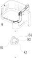
- the buffer pad 8 includes a buffer sheet 81 attached to the window member 3 and a mounting column 82 arranged on one side of the buffer sheet 81, wherein the mounting column 82 and the buffer sheet 81 are integrally formed and are all made of flexible materials.
- Several slots 84 are arranged on the circumferential side wall of the mounting column 82, and the end portion of the mounting column 82 has positioning hole 83.
- the side wall of the window rear cover 2 corresponding to the buffer pads 8 is provided with a socket 23 for inserting the mounting column 82, and the inner wall of the socket 23 is provided with convex ribs 24 embedded in corresponding slots 84, wherein the bottom of the socket 23 is provided with a positioning column 25 inserted into the positioning hole 83.
- the insertion connection between the slot 84 and the convex rib 24 can prevent the buffer pad 8 from rotating, and the positioning hole 83 can perform central orientation for the buffer pad 8 when installing the buffer pad 8.
- the end face of the buffer sheet 81 can be flatly attached to the window member 3, thereby effectively supporting the window member 3.
- the rear door panel 4 is provided with a positioning groove 42 corresponding to the window member 3, wherein the edge of the window member 3 is at least partly located inside the groove 42.
- the groove 42 can position the window member 3, which is convenient for installation and can also play a role in preventing heat from overflowing.
- the frying basket 10 is connected with the rear door panel 4 through several fasteners 9, as shown in Fig. 5-Fig. 6 , the fasteners 9 are located outside the hollow portion.
- the rear door panel 4 and the frying basket 10 are connected internally through multiple fasteners 9, and the fasteners 9 are relatively scattered, such that the connection is relatively firm and reliable.
- the positions of the fasteners 9 between the rear door panel 4 and the frying basket 10 avoid the positions of the window member 3 and the window rear cover 2, thereby realizing that the window member and the window rear cover are clamped and fixed in the cavity therebetween, thus improving the firmness of the structure.
- the inner wall of the frying basket 10 is provided with a frying panel supporting step 7, wherein the hollow portion of the frying basket 10 is located on the upper side of the frying panel supporting step 7, and the frying panel supporting step 7 can prevent frying the panel.
- Food is placed on the frying panel, so that the food on the frying panel can be directly seen through the hollow portion, which is very convenient.
- the side wall of the rear door panel 4 facing the frying basket 10 is provided with a frying basket positioning groove 43, wherein the outwardly extending edge of the upper end of the frying basket 10 extends into the frying basket positioning groove 43.
- the edge can be first inserted into the frying basket positioning groove 43 for positioning, which is convenient for installation.
- the edge embedded in the frying basket positioning groove 43 can also prevent the leakage of heat.
- the fastener 9 configured for the handle installation can be arranged in the frying basket positioning groove 43, such that the handle is fixed from the inside, which saves space.
- a heat dissipation channel 14 is formed between the outside of the cooking chamber 1 and the body of the air fryer, wherein an illumination light 16 is arranged in the heat dissipation channel 14.
- the position corresponding to the illumination light 16 on the cooking chamber 1 is provided with a light-transmitting member 15, wherein the light emitted by the illumination light 16 is irradiated into the cooking chamber 1 through the light-transmitting member 15, so that the illumination light 16 is separated from the cooking chamber 1.
- the temperature change in the cooking chamber 1 will not affect the lifespan of the illumination light 16, and the heat generated by the illumination light 16 can be taken away by the cold air in the heat dissipation channel 14, thereby prolonging the lifespan of the illumination light 16 greatly.
- the cooking chamber 1 is formed by the lower machine core 12 and the air duct plate 18 on the upper side of the lower machine core 12, wherein the heat dissipation channel 14 is formed between the air duct plate 18 and the upper machine core 17 on its upper side.
- the illumination light 16 is located in the heat dissipation channel 14, the position corresponding to the illumination light 16 on the air duct plate 18 has an opening, wherein the light-transmitting member 15 is installed at the opening.
- the lighting manner from top to bottom is generally preferred, and the heat dissipation channel 14 formed between the air duct plate 18 and the upper machine core 17 is more suitable.
- the illumination light 16 can be disassembled by disassembling the upper machine core 17 when disassembling.
- the illumination light 16 can be installed on the upper machine core 17, and its power cord directly enters the upper machine core 17 to be electrically connected with the control element, wherein the operation of the illumination light 16 is controlled by the control element.
- the illumination light 16 itself is not in contact with the air duct plate 18, so there is no contact heat conduction.
- the position corresponding to the illumination light 16 is opened on the air duct plate 18, wherein the light-transmitting member 15 is installed at the opening.
- the air duct plate 18 is an independent part, and it is easier to form an opening on it, and the area of the light-transmitting member 15 can also be made larger to increase the lighting area.
- the opening on the side wall of the air duct plate 18 is provided with a concave part.
- the light-transmitting member 15 is embedded in the concave part for positioning, and simultaneously, is connected to the air duct plate 18.
- the light-transmitting member 15 herein is light-transmitting glass, which generally adopts heat-insulating glass.
- a sealing member is arranged between the light-transmitting member 15 and the air duct plate 18, to prevent the heat in the cooking chamber from leaking.
- the top and bottom of the body are provided with cold air inlets, and the sides of the body are provided with cold air outlets, wherein the cold air inlets and the cold air outlets are all in communication with the heat dissipation channel 14.
- the upper side of the cooking chamber 1 is installed with the cooling fan 19 that communicates with the heat dissipation channel 14, the cold air can be inhaled from cold air inlets at the top and bottom of body by cooling fan 19, then can be led to and discharged through the cold air outlets, thereby improving the flow rate of cold air in the heat dissipation channel 14.
- a cooling fan 19 also can be installed in the upper machine core 17, so that the cold air can be inhaled quickly from the top of the body conveniently.
Landscapes
- Engineering & Computer Science (AREA)
- Food Science & Technology (AREA)
- Frying-Pans Or Fryers (AREA)
Applications Claiming Priority (3)
| Application Number | Priority Date | Filing Date | Title |
|---|---|---|---|
| CN202120304361.0U CN214631740U (zh) | 2021-02-03 | 2021-02-03 | 一种带透明视窗的空气炸锅 |
| CN202120304344.7U CN215937094U (zh) | 2021-02-03 | 2021-02-03 | 一种可视化空气炸锅的照明结构 |
| PCT/CN2021/112479 WO2022166149A1 (zh) | 2021-02-03 | 2021-08-13 | 一种带透明视窗的空气炸锅 |
Publications (3)
| Publication Number | Publication Date |
|---|---|
| EP4289318A1 true EP4289318A1 (de) | 2023-12-13 |
| EP4289318A4 EP4289318A4 (de) | 2024-06-05 |
| EP4289318B1 EP4289318B1 (de) | 2026-04-29 |
Family
ID=82740612
Family Applications (1)
| Application Number | Title | Priority Date | Filing Date |
|---|---|---|---|
| EP21924149.4A Active EP4289318B1 (de) | 2021-02-03 | 2021-08-13 | Luftfriteuse mit transparentem fenster |
Country Status (3)
| Country | Link |
|---|---|
| US (1) | US20240122402A1 (de) |
| EP (1) | EP4289318B1 (de) |
| WO (1) | WO2022166149A1 (de) |
Families Citing this family (3)
| Publication number | Priority date | Publication date | Assignee | Title |
|---|---|---|---|---|
| CN113925362B (zh) * | 2021-10-25 | 2024-04-02 | 广东布鲁斯智能科技有限公司 | 一种多加热腔空气炸锅 |
| USD1111636S1 (en) * | 2022-05-19 | 2026-02-10 | Versuni Holding B.V. | Air fryer |
| WO2025230703A1 (en) * | 2024-05-02 | 2025-11-06 | The Steelstone Group Llc | Cooking appliance with projected display |
Family Cites Families (11)
| Publication number | Priority date | Publication date | Assignee | Title |
|---|---|---|---|---|
| CN102824120A (zh) * | 2012-09-24 | 2012-12-19 | 张一骋 | 一种无烟空气炸锅 |
| CN205963849U (zh) * | 2016-05-24 | 2017-02-22 | 飞利浦(中国)投资有限公司 | 空气炸锅 |
| CN206525958U (zh) * | 2016-11-22 | 2017-09-29 | 深圳市联创三金电器有限公司 | 利用热空气制作食物的设备 |
| CN208864120U (zh) * | 2018-06-08 | 2019-05-17 | 中山市金旲桥电器有限公司 | 一种均匀加热的空气炸锅 |
| CN209610896U (zh) * | 2019-01-24 | 2019-11-12 | 慈溪市悦达电子科技有限公司 | 用于空气炸锅的可视门结构 |
| CN210138081U (zh) * | 2019-03-08 | 2020-03-13 | 袁济时 | 一种可视的抽屉式空气炸锅 |
| CN209996067U (zh) * | 2019-03-11 | 2020-01-31 | 九阳股份有限公司 | 一种密封性好的空气炸锅 |
| CN210185380U (zh) * | 2019-04-29 | 2020-03-27 | 郭鑫 | 空气炸锅 |
| CN212415517U (zh) * | 2020-03-30 | 2021-01-29 | 慈溪市悦达电子科技有限公司 | 一种可视化的空气炸锅锅体 |
| CN212165641U (zh) * | 2020-04-30 | 2020-12-18 | 广东美的厨房电器制造有限公司 | 烹饪器具 |
| CN111802923A (zh) * | 2020-07-15 | 2020-10-23 | 宁波市嘉乐电器有限公司 | 一种具有可拆卸式炸锅组件的空气炸锅 |
-
2021
- 2021-08-13 EP EP21924149.4A patent/EP4289318B1/de active Active
- 2021-08-13 WO PCT/CN2021/112479 patent/WO2022166149A1/zh not_active Ceased
- 2021-08-13 US US18/275,495 patent/US20240122402A1/en active Pending
Also Published As
| Publication number | Publication date |
|---|---|
| EP4289318B1 (de) | 2026-04-29 |
| US20240122402A1 (en) | 2024-04-18 |
| WO2022166149A1 (zh) | 2022-08-11 |
| EP4289318A4 (de) | 2024-06-05 |
Similar Documents
| Publication | Publication Date | Title |
|---|---|---|
| EP4289318B1 (de) | Luftfriteuse mit transparentem fenster | |
| KR20190007891A (ko) | 냉장고 | |
| CN209932464U (zh) | 一种烤箱 | |
| CN215937094U (zh) | 一种可视化空气炸锅的照明结构 | |
| CN218791895U (zh) | 空气炸锅 | |
| CN215215890U (zh) | Led工作灯 | |
| CN220308927U (zh) | 具有显示功能的烹饪器具 | |
| CN219629422U (zh) | 一种空气炸锅 | |
| CN219895227U (zh) | 一种冷柜 | |
| CN113017443A (zh) | 烹饪设备 | |
| CN223298944U (zh) | 一种可视化空气炸锅 | |
| CN223613697U (zh) | 散热结构、料理装置以及集成灶 | |
| CN217875527U (zh) | 一种空气炸锅照明系统 | |
| CN221122316U (zh) | 一种灶具底壳 | |
| CN116369744A (zh) | 烹饪箱体和烹饪器具 | |
| CN224112511U (zh) | 厨房电器用的电源盒结构及厨房电器 | |
| CN105466002A (zh) | 凉炉 | |
| CN221997635U (zh) | 一种具有双独立高效散热风道的多功能烤箱 | |
| CN216789994U (zh) | 一种角灯 | |
| CN224230077U (zh) | 一种烹饪设备 | |
| CN213248397U (zh) | 烹饪器具 | |
| CN114831517B (zh) | 固定组件及烹饪设备 | |
| CN221122132U (zh) | 烧烤炉用的照明灯及烧烤炉 | |
| CN214258915U (zh) | 电饭煲 | |
| CN223913993U (zh) | 炉门组件和烹饪器具 |
Legal Events
| Date | Code | Title | Description |
|---|---|---|---|
| STAA | Information on the status of an ep patent application or granted ep patent |
Free format text: STATUS: THE INTERNATIONAL PUBLICATION HAS BEEN MADE |
|
| PUAI | Public reference made under article 153(3) epc to a published international application that has entered the european phase |
Free format text: ORIGINAL CODE: 0009012 |
|
| STAA | Information on the status of an ep patent application or granted ep patent |
Free format text: STATUS: REQUEST FOR EXAMINATION WAS MADE |
|
| 17P | Request for examination filed |
Effective date: 20230720 |
|
| AK | Designated contracting states |
Kind code of ref document: A1 Designated state(s): AL AT BE BG CH CY CZ DE DK EE ES FI FR GB GR HR HU IE IS IT LI LT LU LV MC MK MT NL NO PL PT RO RS SE SI SK SM TR |
|
| DAV | Request for validation of the european patent (deleted) | ||
| DAX | Request for extension of the european patent (deleted) | ||
| STAA | Information on the status of an ep patent application or granted ep patent |
Free format text: STATUS: EXAMINATION IS IN PROGRESS |
|
| A4 | Supplementary search report drawn up and despatched |
Effective date: 20240507 |
|
| RIC1 | Information provided on ipc code assigned before grant |
Ipc: A47J 37/06 20060101AFI20240430BHEP |
|
| 17Q | First examination report despatched |
Effective date: 20240517 |
|
| GRAP | Despatch of communication of intention to grant a patent |
Free format text: ORIGINAL CODE: EPIDOSNIGR1 |
|
| STAA | Information on the status of an ep patent application or granted ep patent |
Free format text: STATUS: GRANT OF PATENT IS INTENDED |
|
| INTG | Intention to grant announced |
Effective date: 20251222 |
|
| GRAS | Grant fee paid |
Free format text: ORIGINAL CODE: EPIDOSNIGR3 |
|
| GRAA | (expected) grant |
Free format text: ORIGINAL CODE: 0009210 |
|
| STAA | Information on the status of an ep patent application or granted ep patent |
Free format text: STATUS: THE PATENT HAS BEEN GRANTED |
|
| AK | Designated contracting states |
Kind code of ref document: B1 Designated state(s): AL AT BE BG CH CY CZ DE DK EE ES FI FR GB GR HR HU IE IS IT LI LT LU LV MC MK MT NL NO PL PT RO RS SE SI SK SM TR |
|
| REG | Reference to a national code |
Ref country code: CH Ref legal event code: F10 Free format text: ST27 STATUS EVENT CODE: U-0-0-F10-F00 (AS PROVIDED BY THE NATIONAL OFFICE) Effective date: 20260429 Ref country code: GB Ref legal event code: FG4D |
|
| REG | Reference to a national code |
Ref country code: DE Ref legal event code: R096 Ref document number: 602021053438 Country of ref document: DE |