EP4288902B1 - Rfid-funketikett zum befestigen an einer textilie - Google Patents
Rfid-funketikett zum befestigen an einer textilie Download PDFInfo
- Publication number
- EP4288902B1 EP4288902B1 EP22708327.6A EP22708327A EP4288902B1 EP 4288902 B1 EP4288902 B1 EP 4288902B1 EP 22708327 A EP22708327 A EP 22708327A EP 4288902 B1 EP4288902 B1 EP 4288902B1
- Authority
- EP
- European Patent Office
- Prior art keywords
- rfid tag
- carrier material
- textile
- rfid radio
- fastening
- Prior art date
- Legal status (The legal status is an assumption and is not a legal conclusion. Google has not performed a legal analysis and makes no representation as to the accuracy of the status listed.)
- Active
Links
Images
Classifications
-
- G—PHYSICS
- G06—COMPUTING OR CALCULATING; COUNTING
- G06K—GRAPHICAL DATA READING; PRESENTATION OF DATA; RECORD CARRIERS; HANDLING RECORD CARRIERS
- G06K19/00—Record carriers for use with machines and with at least a part designed to carry digital markings
- G06K19/06—Record carriers for use with machines and with at least a part designed to carry digital markings characterised by the kind of the digital marking, e.g. shape, nature, code
- G06K19/067—Record carriers with conductive marks, printed circuits or semiconductor circuit elements, e.g. credit or identity cards also with resonating or responding marks without active components
- G06K19/07—Record carriers with conductive marks, printed circuits or semiconductor circuit elements, e.g. credit or identity cards also with resonating or responding marks without active components with integrated circuit chips
- G06K19/077—Constructional details, e.g. mounting of circuits in the carrier
- G06K19/07749—Constructional details, e.g. mounting of circuits in the carrier the record carrier being capable of non-contact communication, e.g. constructional details of the antenna of a non-contact smart card
- G06K19/07773—Antenna details
-
- G—PHYSICS
- G06—COMPUTING OR CALCULATING; COUNTING
- G06K—GRAPHICAL DATA READING; PRESENTATION OF DATA; RECORD CARRIERS; HANDLING RECORD CARRIERS
- G06K19/00—Record carriers for use with machines and with at least a part designed to carry digital markings
- G06K19/02—Record carriers for use with machines and with at least a part designed to carry digital markings characterised by the selection of materials, e.g. to avoid wear during transport through the machine
- G06K19/027—Record carriers for use with machines and with at least a part designed to carry digital markings characterised by the selection of materials, e.g. to avoid wear during transport through the machine the material being suitable for use as a textile, e.g. woven-based RFID-like labels designed for attachment to laundry items
-
- G—PHYSICS
- G06—COMPUTING OR CALCULATING; COUNTING
- G06K—GRAPHICAL DATA READING; PRESENTATION OF DATA; RECORD CARRIERS; HANDLING RECORD CARRIERS
- G06K19/00—Record carriers for use with machines and with at least a part designed to carry digital markings
- G06K19/06—Record carriers for use with machines and with at least a part designed to carry digital markings characterised by the kind of the digital marking, e.g. shape, nature, code
- G06K19/067—Record carriers with conductive marks, printed circuits or semiconductor circuit elements, e.g. credit or identity cards also with resonating or responding marks without active components
- G06K19/07—Record carriers with conductive marks, printed circuits or semiconductor circuit elements, e.g. credit or identity cards also with resonating or responding marks without active components with integrated circuit chips
- G06K19/0723—Record carriers with conductive marks, printed circuits or semiconductor circuit elements, e.g. credit or identity cards also with resonating or responding marks without active components with integrated circuit chips the record carrier comprising an arrangement for non-contact communication, e.g. wireless communication circuits on transponder cards, non-contact smart cards or RFIDs
Definitions
- the present invention relates to an RFID radio label for attachment to a textile, with a transponder unit which is attached to a flexible carrier material and has an integrated circuit with a conductor structure electrically connected via contact surfaces.
- the invention relates to methods for attaching the RFID radio label according to the invention to a textile.
- RFID radio tags are used in a wide range of applications to detect or identify objects. Especially in connection with the identification of textiles, RFID radio tags are often exposed to high mechanical stress and require an invisible and imperceptible integration into the textile. In the case of clothing in particular, an integration of the RFID radio tag that does not impair wearing comfort is therefore expected. In addition, reliable data transmission between the RFID radio tag and a reader must always be guaranteed.
- US 2005/0093678 A1 shows an RFID radio tag with a chip with contact surfaces and an antenna structure formed from two arms separated by an elongated slot.
- the antenna structure consists of a conductive layer applied to a flexible substrate.
- the radio tag can be attached to a piece of clothing.
- US 2019/0171921 A1 discloses an RFID tag embedded in a textile material, wherein the antenna is inserted in a thread-like channel formed in the flexible material.
- the present invention is therefore based on the object of integrating an RFID radio label into the textile in a way that is almost invisible and imperceptible, taking into account the special mechanical stress.
- the carrier material has a conductor structure with a longitudinal slot that separates the contact surfaces of opposite polarity from one another, the carrier material being shaped in strip form with a length-width ratio that is a multiple of 10, i.e. preferably greater than 20, the thickness of the carrier material preferably being smaller than its width.
- the resulting particularly slim design of the carrier material means that the rigidity that is usually present in the plane of the film in a film that is usually flat is minimized, i.e. there is essentially no flexural rigidity regardless of the direction of loading transverse to the longitudinal axis of the carrier material and the strength of the carrier material is essentially determined by the tensile strength.
- the basic idea of the present invention is to make the carrier material strip-shaped and extremely narrow. This means that the RFID radio label can be easily bent along its longitudinal axis without being rigid or obstructive.
- the RFID radio label according to the invention is therefore much larger in length than commercially available RFID radio labels, but its width and height are so small that it can no longer be felt in the textile and does not add any flexural rigidity to the textile, i.e. it is not noticeable when the textile is touched.
- the conductor structure has a longitudinal slot that determines the distance between the antenna dipoles running in the longitudinal direction of the carrier material and that separates the contact surfaces of opposite polarity from one another in order to tap the potential difference (electrical voltage) of the dipole antenna (folded dipole) thus formed and to pass it on to the integrated circuit (chip).
- the length and width of the longitudinal slot primarily determine the resonance frequency of the RFID radio tag.
- the longitudinal slot is T-shaped, wherein the long T-leg running in the longitudinal direction of the carrier material determines the distance between the antenna dipoles running in the longitudinal direction of the carrier material, whereas the short T-leg separates the contact surfaces of opposite polarity from one another in order to tap the potential difference (electrical voltage) of the dipole antenna (folded dipole) and to transmit it to the integrated circuit (chip).
- the term slot is to be understood as meaning that the slot enables the formation of the conductor structure, i.e. the slot in the conductor structure forming Material is provided and does not have to be additionally formed in the carrier material.
- the carrier material is provided with a longitudinal reinforcement, which can be formed from the carrier material itself or as a supplement to the carrier material, in particular as a longitudinal thread or a longitudinal fiber extending in the longitudinal direction of the carrier material and connected to the carrier material.
- the carrier material can be formed as a fiber composite material.
- the length-width ratio is greater than 20, more preferably greater than 50, and most preferably greater than 100.
- the carrier material is designed as a film material provided with a metallization, in particular designed as a surface metallization.
- the carrier material is preferably made of PET film with aluminum metallization.
- This design achieves high mechanical resilience combined with good electrical (antenna) properties and cost-efficient production.
- the carrier material consists of a stretchable material.
- the material selection can be made in such a way that the RFID radio tag carrier material has sufficient elasticity. However, it is important to ensure that the area of the integrated circuit (chip area) is relieved.
- the stretchable carrier material can be a plastic-free material.
- the carrier material can be pre-folded at the end areas.
- the (dipole) end areas are slightly pre-folded.
- the end sections of the RFID radio tag have specific round or specific square contours to adapt the transmission bandwidth.
- the end sections of the RFID radio label have single or multiple round or square edges, for example jagged or diagonally cut, that are specifically adapted to the transmission bandwidth.
- the object underlying the invention is further achieved by a method for attaching the RFID radio label according to the invention, wherein the RFID radio label is attached at exactly one point.
- the RFID radio label is only attached in one area - a small area in relation to the length of the RFID radio label - preferably in the central area where the electrical circuit (chip) is located.
- the two legs of the carrier material, which form the dipole legs of the conductor structure, are not connected to the textile and remain movably integrated in the textile, for example just loosely inserted in the seam.
- the point-based fastening is done by sewing or gluing.
- the point-by-point fastening is carried out in a simple, reliable and cost-effective manner by sewing or gluing.
- the RFID radio label is attached in a floating manner by sewing around, wherein the RFID radio label is arranged between the puncture points of a sewing thread in the textile.
- the RFID radio label is thus movably mounted in the textile in the manner of a tunnel, surrounded by the sewing thread, so that only small forces, in particular no tensile forces in the longitudinal direction, are transferred to the RFID radio label.
- a reinforcing seam can additionally be inserted into the textile along a longitudinal axis of the RFID radio label in a fastening area of the RFID radio label.
- the reinforcement seam prevents the textile from stretching in the area of the RFID radio tag and thus represents another simple and effective measure for protecting the RFID radio tag during its attachment.
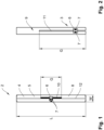
- Transponder unit 05 which is attached to a flexible carrier material 04.
- the transponder unit 05 consists of an integrated circuit 06 (chip) and a conductor structure 08 (antenna) connected to the integrated circuit 06 by means of contact surfaces 07.
- the carrier material 04 consists of a thin PET film with aluminum metallization and thus forms a conductor structure 08.
- a T-shaped longitudinal slot 10 in the carrier material 04 according to the invention allows the electrically conductive carrier material 04 to act as a dipole antenna (folded dipole), the contact surfaces 07 with the integrated circuit 06 being separated in their polarity by the T-shaped slot 10 in order to tap the voltage at the dipole ends.
- the resonance-determining length G of the longitudinal slot is preferably in a range of 30 to 50 mm.
- the size ratio of length L to width W of the carrier material 04 is preferably more than 50, whereby an extremely narrow, almost thread-like RFID radio label 02 is formed.
- Fig. 2 shows in a known embodiment an RFID radio tag 3 which has a longitudinal slot 11 for forming a conductor structure 9, which determines both the distance between the longitudinally directed conductors of the carrier material extending antenna dipoles and also separates the contact surfaces 7 of opposite polarity from each other in order to tap the potential difference of the dipole antenna thus formed and forward it to the integrated circuit 6.
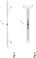
- Fig. 3 shows an RFID radio label 02 pre-folded in its end regions 22.
- the slightly pre-folded end regions 22 reduce the tensile force on the central region of the RFID radio label 02 occupied by the chip and counteract a (creeping) stretching of the textile 30.
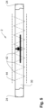
- Fig. 4 shows an attachment of the RFID radio label 02 on the textile 30.
- the textile 30 is provided with a reinforcing seam 32 in the area of the RFID radio label 02.
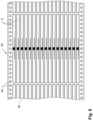
- Fig. 5 shows an attachment of the RFID radio label 02 by sewing around it with a sewing thread 44.
- the puncture points 42 of the sewing thread 44 are arranged lengthwise outside the RFID radio label 02, so that the RFID radio label 02 is floating between the puncture points 42.
- the end sections of the RFID radio label 02 have specific round or specific square contours 24 to adapt the transmission bandwidth.
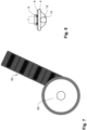
- Fig. 6 shows a transport arrangement 50 in which the RFID radio labels 02 are arranged in the longitudinal direction on a transport film 52 with transport holes 54.
- the longitudinal arrangement offers the advantage that the aluminum as a component of the carrier material 04 is applied in the running direction of the RFID radio label 02 and is therefore more resistant to tensile stress, which in turn proves to be an advantage with regard to the tear resistance when stretched.
- FIG. 7 For clarification purposes, the figure shows schematically the transport arrangement 50 during unwinding from a transport roll 60.
- the roll format is ideal for producing large quantities and is particularly suitable for supplying the RFID radio label 02 during textile production.
- Fig. 8 shows how, in the aforementioned production, a carrier thread can additionally be attached as longitudinal reinforcement 12 on the back of the carrier material 4 of the RFID radio label 02 with the aid of the transport roller 60.
- the carrier thread 12 is generously integrated in an adhesive bed 14.
Landscapes
- Engineering & Computer Science (AREA)
- Physics & Mathematics (AREA)
- General Physics & Mathematics (AREA)
- Theoretical Computer Science (AREA)
- Textile Engineering (AREA)
- Computer Networks & Wireless Communication (AREA)
- Computer Hardware Design (AREA)
- Microelectronics & Electronic Packaging (AREA)
- Details Of Aerials (AREA)
- Waveguide Aerials (AREA)
Description
- Die vorliegende Erfindung betrifft ein RFID-Funketikett zum Befestigen an einer Textilie, mit einer Transpondereinheit, welche auf einem biegsamen Trägermaterial angebracht ist und eine integrierte Schaltung mit einer über Kontaktflächen elektrisch verbundenen Leiterstruktur aufweist.
- Weiterhin betrifft die Erfindung Verfahren zum Befestigen des erfindungsgemäßen RFID-Funketiketts an einer Textilie.
- RFID-Funketiketten werden in vielfältigen Anwendungsbereichen zur Erkennung oder zum Identifizieren von Gegenständen eingesetzt. Insbesondere in Verbindung mit der Identifizierung von Textilien sind RFID-Funketiketten oftmals einer hohen mechanischen Beanspruchung ausgesetzt und verlangen nach einer unsichtbaren und unfühlbaren Integration in die Textilie. Gerade bei Kleidungsstücken wird daher eine nicht den Tragekomfort beeinträchtigende Integration des RFID-Funketiketts erwartet. Darüber hinaus muss stets eine zuverlässige Datenübertragung zwischen dem RFID-Funketikett und einem Lesegerät gewährleistet sein.
- Die Offenlegungsschrift
US 2005/0093678 A1 zeigt ein RFID-Funketikett mit einem Chip mit Kontaktflächen sowie eine Antennenstruktur, die aus zwei durch einen länglichen Schlitz getrennten Armen gebildet ist. Die Antennenstruktur besteht aus einer leitfähigen Schicht, die auf einem flexiblen Substrat aufgebracht ist. Das Funketikett kann auf einem Kleidungsstück befestigt werden. - In der Offenlegungsschrift
US 2019/0171921 A1 ist ein in ein textiles Material eingebettetes RFID-Tag offenbart, wobei die Antenne in einem in dem flexiblen Material ausgebildeten Kanal fadenförmig eingebracht wird. - Der vorliegenden Erfindung liegt daher die Aufgabe zugrunde, ein RFID-Funketikett nahezu unsichtbar und unfühlbar unter Berücksichtigung der besonderen mechanischen Beanspruchung in die Textilie zu integrieren.
- Diese Aufgabe wird dadurch gelöst, dass das Trägermaterial eine Leiterstruktur mit einem Längsschlitz aufweist, der die Kontaktflächen entgegengesetzter Polarität voneinander trennt, wobei das Trägermaterial streifenförmig mit einem Länge-Breite-Verhältnis, das ein Mehrfaches 10-faches beträgt, also vorzugsweise größer als 20 ist, geformt ist, wobei die Dicke des Trägermaterials vorzugsweise kleiner ist als dessen Breite. Die hieraus resultierende besonders schlanke Ausgestaltung des Trägermaterials führt dazu, dass die bei einer üblicherweise flächig ausgebildeten Folie in der Folienebene ausgeprägte Steifigkeit minimiert wird, also unabhängig von der Belastungsrichtung quer zur Längsachse des Trägermaterials im Wesentlichen keine Biegesteifigkeit vorhanden ist und die Festigkeit des Trägermaterials im Wesentlichen durch die Zugfestigkeit bestimmt ist.
- Aufgrund der insbesondere bei Kleidungsstücken vorherrschenden inhomogenen Textilbeschaffenheit, der begrenzten Anbringungsflächen und der daraus resultierenden eingeschränkten Befestigungsmöglichkeiten kann die Leiterstruktur (Antennengeometrie) nicht beliebig dimensioniert werden.
- Die Grundidee der vorliegenden Erfindung besteht somit darin, das Trägermaterial streifenförmig und extrem schmal auszubilden. Somit lässt sich das RFID-Funketikett in seiner Längsachse leicht biegen, ohne starr und behindernd zu wirken. Das erfindungsgemäße RFID-Funketikett besitzt damit zwar in Längsrichtung eine im Vergleich zu handelsüblichen RFID-Funketiketten sehr viel größere Ausdehnung, ist jedoch in seiner Breite und Höhe so klein bemessen, dass es in der Textilie nicht mehr zu ertasten ist und keine Biegesteifigkeit in die Textile einbringt, also im textilen Griff nicht wahrnehmbar ist.
- Damit das metallisierte Trägermaterial in seiner Funktion als Leiterstruktur die Wirkung einer Dipolantenne entfaltet, weist die Leiterstruktur einen Längsschlitz auf, der den Abstand der in Längsrichtung des Trägermaterials verlaufenden Antennendipole bestimmt und der die Kontaktflächen entgegengesetzter Polarität voneinander trennt, um den Potentialunterschied (elektrische Spannung) der so ausgebildeten Dipolantenne (Faltdipol) abzugreifen und an die integrierte Schaltung (Chip) weiterzuleiten. Die Länge und Breite des Längsschlitzes bestimmen dabei primär die Resonanzfrequenz des RFID-Funketiketts.
- Erfindungsgemäß ist der Längsschlitz T-förmig ausgebildet, wobei der in Längsrichtung des Trägermaterials verlaufende lange T-Schenkel den Abstand der in Längsrichtung des Trägermaterials verlaufenden Antennendipole bestimmt, wohingegen der kurze T-Schenkel die Kontaktflächen entgegengesetzter Polarität voneinander trennt, um den Potentialunterschied (elektrische Spannung) der Dipolantenne (Faltdipol) abzugreifen und an die integrierte Schaltung (Chip) weiterzuleiten.
- Im Zusammenhang mit der vorliegenden Erfindung ist der Begriff Schlitz so zu verstehen, dass durch den Schlitz die Ausbildung der Leiterstruktur ermöglicht wird, der Schlitz also in dem die Leiterstruktur ausbildenden Material vorgesehen ist und nicht zusätzlich in dem Trägermaterial ausgebildet sein muss. Vorzugsweise ist das Trägermaterial mit einer Längsverstärkung versehen, die aus dem Trägermaterial selbst oder als Ergänzung zum Trägermaterial, insbesondere als ein sich in Längsrichtung des Trägermaterials erstreckender und mit dem Trägermaterial verbundener Längsfaden oder eine Längsfaser, ausgebildet sein kann. Beispielsweise kann das Trägermaterial als Faserverbundmaterial ausgebildet sein.
- Damit ist eine hohe Reißfestigkeit bei geringer Biegesteifigkeit gewährleistet, sodass das RFID-Funketikett auch in dehnbare Textilien integriert werden kann und dennoch unauffällig wirkt.
- Vorzugsweise ist das Länge-Breite-Verhältnis größer als 20, besonders vorzugsweise größer als 50 und ganz besonders vorzugsweise größer als 100.
- Vorzugsweise ist das Trägermaterial als mit einer insbesondere als Oberflächenmetallisierung ausgebildeten Metallisierung versehenes Folienmaterial ausgeführt.
- Bevorzugt ist das Trägermaterial als PET-Folie mit Aluminium-Metallisierung ausgeführt.
- Durch diese Ausführung wird eine hohe mechanische Belastbarkeit bei gleichzeitig guten elektrischen (Antennen-)Eigenschaften und kosteneffizienter Herstellung erzielt.
- In alternativer Ausgestaltung besteht das Trägermaterial aus einem dehnbaren Material.
- Die Materialauswahl kann so erfolgen, dass das RFID-Funketikett-Trägermaterial eine ausreichende Dehnbarkeit ausweist. Hierbei ist allerdings darauf zu achten, dass der Bereich der integrierten Schaltung (Chip-Bereich) entlastet wird. Das dehnbare Trägermaterial kann ein kunststofffreies Material sein.
- Weiter kann das Trägermaterial an Endbereichen vorgefaltet sein.
- Um eine mechanische Entkopplung von der verformbaren Textilie zu bewirken und einer - auch schleichenden - Dehnung der Textilie entgegenwirken zu können, sind die (Dipol-)Endbereiche leicht vorgefaltet.
- Weiterhin weisen die Endabschnitte des RFID-Funketiketts zur Anpassung der Übertragungsbandbreite spezifische runde oder spezifische eckige Konturen auf.
- Die Endabschnitte des RFID-Funketiketts weisen dabei spezifisch an die Übertragungsbandbreite angepasste, einfache oder mehrfache runde oder eckige, beispielsweise gezackte oder schräg geschnittene, Kanten auf.
- Die der Erfindung zugrunde liegende Aufgabe wird weiter gelöst durch ein Verfahren zum Befestigen des erfindungsgemäßen RFID-Funketiketts, wobei das RFID-Funketikett punktuell an genau einer Stelle befestigt wird.
- Das RFID-Funketikett wird dabei lediglich in nur einem - bezogen auf die Längsausdehnung des RFID-Funketiketts kleinen - Bereich, vorzugsweise in dem Zentralbereich, wo der elektrische Schaltkreis (Chip) angeordnet ist, befestigt. Die beiden Schenkel des Trägermaterials, welche die Dipolschenkel der Leiterstruktur ausbilden, werden nicht mit der Textilie verbunden und verbleiben beweglich integriert in der Textilie, beispielsweise lediglich lose in dem Saum eingelegt.
- Bevorzugt erfolgt die punktuelle Befestigung durch Nähen oder Verkleben.
- Die punktuelle Befestigung erfolgt in fertigungstechnisch einfacher, zuverlässiger und kostengünstiger Weise durch Nähen oder Verkleben.
- In einem alternativen Verfahren zur Befestigung des erfindungsgemäßen RFID-Funketiketts wird das RFID-Funketikett durch Umnähen schwimmend befestigt, wobei das RFID-Funketikett zwischen den Einstichstellen eines Nähfadens in der Textilie angeordnet ist.
- Das RFID-Funketikett wird somit in der Art eines Tunnels von dem Nähfaden umschlossen in dem Textil beweglich gelagert, sodass nur geringe Kräfte, insbesondere keine Zugkräfte in Längsrichtung, auf das RFID-Funketikett übertragen werden.
- In beiden vorgenannten Befestigungsverfahren kann in einem Befestigungsbereich des RFID-Funketiketts zusätzlich eine Verstärkungsnaht in der Textilie entlang einer Längsachse des RFID-Funketiketts eingezogen werden.
- Die Verstärkungsnaht verhindert, dass sich die Textilie im Bereich des RFID-Funketiketts dehnt und stellt somit eine weitere einfache und wirkungsvolle Maßnahme zum Schutz des RFID-Funketiketts bei seiner Befestigung dar.
- Weitere vorteilhafte Ausgestaltungsmerkmale ergeben sich aus der nachfolgenden Beschreibung und den Zeichnungen, die bevorzugte Ausführungsformen der Erfindung anhand von Beispielen erläutern.
- Es zeigen:
- Fig. 1
- eine bevorzugte Ausführungsform eines erfindungsgemäßen RFID-Funketiketts,
- Fig. 2
- eine bekannte Ausführungsform,
- Fig. 3
- eine Ausgestaltung mit vorgefalteten Endbereichen,
- Fig. 4
- eine Befestigung mit zusätzlicher Verstärkungsnaht in der Textilie,
- Fig. 5
- eine Befestigung durch Umnähen,
- Fig. 6
- eine Transportanordnung bei der Herstellung,
- Fig. 7
- die Transportanordnung nach
Fig. 5 mit Transportrolle, und - Fig. 8
- die Transportanordnung nach
Fig. 5 mit Trägerfaden. - Fig. 1
- zeigt ein erfindungsgemäßes RFID-Funketikett 02 mit einer
- Transpondereinheit 05, die auf einem biegsamen Trägermaterial 04 angebracht ist. Die Transpondereinheit 05 besteht aus einer integrierten Schaltung 06 (Chip) und einer mittels Kontaktflächen 07 mit der integrierten Schaltung 06 verbundenen Leiterstruktur 08 (Antenne).
- Vorzugsweise besteht das Trägermaterial 04 aus einer dünnen PET-Folie mit Aluminiummetallisierung und bildet somit eine Leiterstruktur 08 aus.
- Ein erfindungsgemäß T-förmiger Längsschlitz 10 in dem Trägermaterial 04 lässt das elektrisch leitfähige Trägermaterial 04 als Dipolantenne (Faltdipol) wirken, wobei die Kontaktflächen 07 mit der integrierten Schaltung 06 durch den T-förmigen Schlitz 10 in ihrer Polarität getrennt werden, um die Spannung an den Dipolenden abzugreifen. Die resonanzbestimmende Länge G des Längsschlitzes liegt vorzugsweise in einem Bereich von 30 bis 50 mm.
- Das Größenverhältnis Länge L zu Breite W des Trägermaterials 04 beträgt vorzugsweise mehr als 50, wodurch ein in seiner Dimensionierung extrem schmales, nahezu fadenförmiges RFID-Funketikett 02 ausgebildet wird. Beispielsweise ist das RFID-Funketikett 02 mit einer Länge L=134 mm und einer Breite W=0,5 bis 2 mm ausgeführt.
- Dabei sind die in den Figuren dargestellten Anordnungen schematische, nicht maßstabsgerechte Darstellungen.
-
Fig. 2 zeigt in einer bekannten Ausführungsform ein RFID-Funketikett 3, das zur Ausbildung einer Leiterstruktur 9 einen Längsschlitz 11 aufweist, der sowohl den Abstand der in Längsrichtung des Trägermaterials verlaufenden Antennendipole bestimmt als auch die Kontaktflächen 7 entgegengesetzter Polarität voneinander trennt, um den Potentialunterschied der so ausgebildeten Dipolantenne abzugreifen und an die integrierte Schaltung 6 weiterzuleiten. -
Fig. 3 zeigt ein in seinen Endbereichen 22 vorgefaltetes RFID-Funketikett 02. Die leicht vorgefalteten Endbereiche 22 vermindern die Zugkraft auf den mit dem Chip belegten Zentralbereich des RFID-Funketiketts 02 und wirken einer (schleichenden) Dehnung der Textilie 30 entgegen. -
Fig. 4 zeigt eine Befestigung des RFID-Funketiketts 02 auf der Textilie 30. Zur Verstärkung und Reduzierung der auf das RFID-Funketikett 02 einwirkenden Kräfte ist die Textilie 30 in dem Bereich des RFID-Funketiketts 02 mit einer Verstärkungsnaht 32 versehen. -
Fig. 5 zeigt eine Befestigung des RFID-Funketiketts 02 durch Umnähen mit einem Nähfaden 44. Dabei sind die Einstichstellen 42 des Nähfadens 44 längsseitig außerhalb des RFID-Funketiketts 02 angeordnet, sodass das RFID-Funketikett 02 zwischen den Einstichstellen 42 schwimmend gelagert ist. - Die Endabschnitte des RFID-Funketiketts 02 weisen zur Anpassung der Übertragungsbandbreite spezifische runde oder spezifische eckige Konturen 24 auf.
-
Fig. 6 zeigt eine Transportanordnung 50, bei der die RFID-Funketiketten 02 auf einer Transportfolie 52 mit Transportlöchern 54 in Längsrichtung angeordnet sind. Die Längsanordnung bietet den Vorteil, dass das Aluminium als Bestandteil des Trägermaterials 04 in Laufrichtung zum RFID-Funketikett 02 aufgebracht wird und somit bei einer Zugbeanspruchung widerstandsfähiger ist, was sich wiederum im Hinblick auf die Reißfestigkeit bei Dehnung als Vorteil erweist. -
Fig. 7 zeigt zur Verdeutlichung schematisch die Transportanordnung 50 bei der Abwicklung von einer Transportrolle 60. - Das Rollenformat bietet sich bei der Herstellung großer Stückzahlen an und eignet sich während der Textilherstellung insbesondere für die Zufuhr des RFID-Funketiketts 02.
-
Fig. 8 zeigt, wie bei der vorgenannten Herstellung mit Hilfe der Transportrolle 60 zusätzlich ein Trägerfaden als Längsverstärkung 12 auf der Rückseite des Trägermaterials 4 des RFID-Funketiketts 02 angebracht werden kann. Der Trägerfaden 12 ist dabei großzügig in einem Klebstoffbett 14 eingebunden.
Claims (13)
- RFID-Funketikett (2, 3) zum Befestigen an einer Textilie (30), mit einer Transpondereinheit (5), welche auf einem biegsamen Trägermaterial (4) angebracht ist und eine integrierte Schaltung (6) mit einer über Kontaktflächen (7) elektrisch verbundenen Leiterstruktur (8, 9) aufweist,
dadurch gekennzeichnet,
dass das Trägermaterial (4) als Leiterstruktur (8) mit einem Längsschlitz (10, 11) ausgebildet ist, der als T-förmiger Schlitz ausgeführt ist, wobei der in Längsrichtung des Trägermaterials (4) verlaufende lange T-Schenkel den Abstand der in Längsrichtung des Trägermaterials (4) verlaufenden Antennendipole bestimmt, wohingegen der kurze T-Schenkel die Kontaktflächen (7) entgegengesetzter Polarität voneinander trennt, wobei das Trägermaterial (4) streifenförmig mit einem Länge (L)/Breite (W)-Verhältnis, das ein Mehrfaches 10-faches beträgt, geformt ist. - RFID-Funketikett (2, 3) nach Anspruch 1,
dadurch gekennzeichnet,
dass das Länge-Breite-Verhältnis größer als 20 ist. - RFID-Funketikett (2, 3) nach Anspruch 1,
dadurch gekennzeichnet,
dass das Länge-Breite-Verhältnis größer als 50 ist. - RFID-Funketikett (2, 3) nach Anspruch 1,
dadurch gekennzeichnet,
dass das Länge-Breite-Verhältnis größer als 100 ist - RFID-Funketikett (2, 3) nach einem der vorangehenden Ansprüche, dadurch gekennzeichnet,
dass die Dicke des Trägermaterials kleiner ist als dessen Breite. - RFID-Funketikett (2, 3) nach einem der vorangehenden Ansprüche, dadurch gekennzeichnet,
dass das Trägermaterial mit einer Längsverstärkung (12) versehen ist. - RFID-Funketikett (2, 3) nach einem der vorangehenden Ansprüche, dadurch gekennzeichnet,
dass das Trägermaterial als PET-Folie mit Aluminium-Metallisierung ausgeführt ist. - RFID-Funketikett (2, 3) nach einem der vorangehenden Ansprüche, dadurch gekennzeichnet,
dass das Trägermaterial (4) aus einem dehnbaren Material ist. - RFID-Funketikett (2) nach einem der vorangehenden Ansprüche, dadurch gekennzeichnet,
dass das Trägermaterial (4) an Endbereichen (22) vorgefaltet ist. - RFID-Funketikett (2, 3) nach einem der vorangehenden Ansprüche, dadurch gekennzeichnet,
dass Endabschnitte des RFID-Funketiketts (2) zur Anpassung der Übertragungsbandbreite spezifische runde oder spezifische eckige Konturen (24) aufweisen. - Verfahren zum Befestigen des RFID-Funketiketts (2, 3) nach Anspruch 1 an einer Textilie (30),
dadurch gekennzeichnet,
dass das RFID-Funketikett (2) punktuell an genau einer Stelle befestigt wird. - Verfahren nach Anspruch 12,
dadurch gekennzeichnet,
dass die punktuelle Befestigung durch Nähen oder Verkleben erfolgt. - Verfahren zum Befestigen des RFID-Funketiketts (2, 3) nach Anspruch 1 an einer Textilie (30),
dadurch gekennzeichnet,
dass das RFID-Funketikett (2) durch Umnähen schwimmend befestigt wird, wobei das RFID-Funketikett (2) zwischen den Einstichstellen (42) eines Nähfadens (44) in der Textilie (30) angeordnet ist.
Applications Claiming Priority (2)
| Application Number | Priority Date | Filing Date | Title |
|---|---|---|---|
| DE102021102349.1A DE102021102349A1 (de) | 2021-02-02 | 2021-02-02 | RFID-Funketikett zum Befestigen an einer Textilie |
| PCT/EP2022/051099 WO2022167221A1 (de) | 2021-02-02 | 2022-01-19 | Rfid-funketikett zum befestigen an einer textilie |
Publications (3)
| Publication Number | Publication Date |
|---|---|
| EP4288902A1 EP4288902A1 (de) | 2023-12-13 |
| EP4288902C0 EP4288902C0 (de) | 2024-10-23 |
| EP4288902B1 true EP4288902B1 (de) | 2024-10-23 |
Family
ID=80682352
Family Applications (1)
| Application Number | Title | Priority Date | Filing Date |
|---|---|---|---|
| EP22708327.6A Active EP4288902B1 (de) | 2021-02-02 | 2022-01-19 | Rfid-funketikett zum befestigen an einer textilie |
Country Status (4)
| Country | Link |
|---|---|
| US (1) | US12254365B2 (de) |
| EP (1) | EP4288902B1 (de) |
| DE (1) | DE102021102349A1 (de) |
| WO (1) | WO2022167221A1 (de) |
Citations (1)
| Publication number | Priority date | Publication date | Assignee | Title |
|---|---|---|---|---|
| WO2002007085A1 (en) * | 2000-07-18 | 2002-01-24 | Marconi Corporation P.L.C. | Wireless communication device and method |
Family Cites Families (9)
| Publication number | Priority date | Publication date | Assignee | Title |
|---|---|---|---|---|
| US7253735B2 (en) | 2003-03-24 | 2007-08-07 | Alien Technology Corporation | RFID tags and processes for producing RFID tags |
| WO2005045755A2 (en) | 2003-11-04 | 2005-05-19 | Avery Dennison Corporation | Rfid tag with enhanced readability |
| DE102005033196A1 (de) | 2005-07-13 | 2007-01-25 | Arccure Technologies Gmbh | Verfahren und Anordnung zur Herstellung von RFID-Tags |
| JP4437475B2 (ja) * | 2006-01-31 | 2010-03-24 | 富士通株式会社 | 折り返しダイポールアンテナ及びこれを使用したタグ |
| EP2019425A1 (de) | 2007-07-27 | 2009-01-28 | Semiconductor Energy Laboratory Co., Ltd. | Halbleiterbauelement und Verfahren zu seiner Herstellung |
| DE102008027246A1 (de) | 2008-06-06 | 2009-12-10 | ASTRA Gesellschaft für Asset Management mbH & Co. KG | Waschbares Produkt |
| JP2011095844A (ja) | 2009-10-27 | 2011-05-12 | Hitachi Ltd | 非接触電子装置 |
| EP2645298A1 (de) * | 2012-03-30 | 2013-10-02 | austriamicrosystems AG | Tragbarer Gegenstand und Informationsübertragungssystem |
| BR112020010906A2 (pt) | 2017-12-01 | 2020-11-17 | Avery Dennison Retail Information Services, Llc | etiquetas de tecido flexível usando aberturas em um substrato |
-
2021
- 2021-02-02 DE DE102021102349.1A patent/DE102021102349A1/de active Pending
-
2022
- 2022-01-19 EP EP22708327.6A patent/EP4288902B1/de active Active
- 2022-01-19 WO PCT/EP2022/051099 patent/WO2022167221A1/de not_active Ceased
- 2022-01-19 US US18/274,420 patent/US12254365B2/en active Active
Patent Citations (1)
| Publication number | Priority date | Publication date | Assignee | Title |
|---|---|---|---|---|
| WO2002007085A1 (en) * | 2000-07-18 | 2002-01-24 | Marconi Corporation P.L.C. | Wireless communication device and method |
Also Published As
| Publication number | Publication date |
|---|---|
| EP4288902A1 (de) | 2023-12-13 |
| US20240095481A1 (en) | 2024-03-21 |
| EP4288902C0 (de) | 2024-10-23 |
| US12254365B2 (en) | 2025-03-18 |
| WO2022167221A1 (de) | 2022-08-11 |
| DE102021102349A1 (de) | 2022-08-04 |
Similar Documents
| Publication | Publication Date | Title |
|---|---|---|
| EP2044258B1 (de) | Rfid-etikette | |
| EP2066836B1 (de) | Rfid-textiletikette | |
| DE102004003461B4 (de) | Textilmaterial mit einem HF-Transponder | |
| EP2162851B1 (de) | Rfid-transponderchipmodul mit verbindungsmittel für eine antenne, textiles etikett mit einem rfid-transponderchipmodul, sowie verwendung eines rfid-transponderchipmoduls | |
| EP0976099A2 (de) | Chipkarte | |
| DE102017006450B4 (de) | RFID-Transponder für eine kontaktlose Kommunikation mit Plastikgehäuse | |
| EP2027626A1 (de) | Mehrschichtige antenne planarer bauart | |
| DE20003965U1 (de) | Einrichtung zur Übertragung elektrischen Stroms zwischen zwei zueinander verdrehbaren Bauelementen einer Lenkeinrichtung für Kraftfahrzeuge | |
| EP1965461A2 (de) | Textilmaterial mit einem Schaltungsmodul und einer Antenne | |
| EP3584934A1 (de) | Variabel einsetzbare sensoreinheit | |
| EP1122685B1 (de) | Chipkarte mit Sollbiegestellen | |
| DE112009002384T5 (de) | Antenne und Drahtlose-IC-Bauelement | |
| DE102006051379A1 (de) | Transponder für Textilien und dessen Herstellungsverfahren | |
| DE10145752A1 (de) | Nicht-leitendes, ein Band oder einen Nutzen bildendes Substrat, auf dem eine Vielzahl von Trägerelementen ausgebildet ist | |
| EP4288902B1 (de) | Rfid-funketikett zum befestigen an einer textilie | |
| DE102007059168A1 (de) | Kommunikationsmodul mit Schlitzantenne | |
| EP1955406B1 (de) | Multiband-rundstrahler | |
| EP4187039A1 (de) | Flächengebildeanordnung | |
| DE102007022615A1 (de) | Kontaktloses Übertragungssystem und Verfahren zum Herstellen desselben | |
| EP2260438B1 (de) | Transpondermodul | |
| DE10107072B4 (de) | Verfahren zur Herstellung einer Chipkarte | |
| DE69932013T2 (de) | Antenne für mobile funkkommunikation | |
| EP2491582B1 (de) | Verfahren zum herstellen von durchkontaktierungen | |
| DE102017216265A1 (de) | Identifikationseinheit sowie Reifen mit einer derartigen Identifikationseinheit | |
| DE1200153B (de) | An der Regenrinne befestigte Kraftfahrzeugantenne |
Legal Events
| Date | Code | Title | Description |
|---|---|---|---|
| STAA | Information on the status of an ep patent application or granted ep patent |
Free format text: STATUS: UNKNOWN |
|
| STAA | Information on the status of an ep patent application or granted ep patent |
Free format text: STATUS: THE INTERNATIONAL PUBLICATION HAS BEEN MADE |
|
| PUAI | Public reference made under article 153(3) epc to a published international application that has entered the european phase |
Free format text: ORIGINAL CODE: 0009012 |
|
| STAA | Information on the status of an ep patent application or granted ep patent |
Free format text: STATUS: REQUEST FOR EXAMINATION WAS MADE |
|
| 17P | Request for examination filed |
Effective date: 20230822 |
|
| AK | Designated contracting states |
Kind code of ref document: A1 Designated state(s): AL AT BE BG CH CY CZ DE DK EE ES FI FR GB GR HR HU IE IS IT LI LT LU LV MC MK MT NL NO PL PT RO RS SE SI SK SM TR |
|
| DAV | Request for validation of the european patent (deleted) | ||
| DAX | Request for extension of the european patent (deleted) | ||
| GRAP | Despatch of communication of intention to grant a patent |
Free format text: ORIGINAL CODE: EPIDOSNIGR1 |
|
| STAA | Information on the status of an ep patent application or granted ep patent |
Free format text: STATUS: GRANT OF PATENT IS INTENDED |
|
| INTG | Intention to grant announced |
Effective date: 20240606 |
|
| GRAS | Grant fee paid |
Free format text: ORIGINAL CODE: EPIDOSNIGR3 |
|
| GRAA | (expected) grant |
Free format text: ORIGINAL CODE: 0009210 |
|
| STAA | Information on the status of an ep patent application or granted ep patent |
Free format text: STATUS: THE PATENT HAS BEEN GRANTED |
|
| AK | Designated contracting states |
Kind code of ref document: B1 Designated state(s): AL AT BE BG CH CY CZ DE DK EE ES FI FR GB GR HR HU IE IS IT LI LT LU LV MC MK MT NL NO PL PT RO RS SE SI SK SM TR |
|
| REG | Reference to a national code |
Ref country code: GB Ref legal event code: FG4D Free format text: NOT ENGLISH |
|
| REG | Reference to a national code |
Ref country code: CH Ref legal event code: EP |
|
| REG | Reference to a national code |
Ref country code: DE Ref legal event code: R096 Ref document number: 502022001966 Country of ref document: DE |
|
| REG | Reference to a national code |
Ref country code: IE Ref legal event code: FG4D Free format text: LANGUAGE OF EP DOCUMENT: GERMAN |
|
| U01 | Request for unitary effect filed |
Effective date: 20241023 |
|
| U07 | Unitary effect registered |
Designated state(s): AT BE BG DE DK EE FI FR IT LT LU LV MT NL PT RO SE SI Effective date: 20241107 |
|
| U20 | Renewal fee for the european patent with unitary effect paid |
Year of fee payment: 4 Effective date: 20250121 |
|
| PG25 | Lapsed in a contracting state [announced via postgrant information from national office to epo] |
Ref country code: IS Free format text: LAPSE BECAUSE OF FAILURE TO SUBMIT A TRANSLATION OF THE DESCRIPTION OR TO PAY THE FEE WITHIN THE PRESCRIBED TIME-LIMIT Effective date: 20250223 Ref country code: HR Free format text: LAPSE BECAUSE OF FAILURE TO SUBMIT A TRANSLATION OF THE DESCRIPTION OR TO PAY THE FEE WITHIN THE PRESCRIBED TIME-LIMIT Effective date: 20241023 |
|
| PG25 | Lapsed in a contracting state [announced via postgrant information from national office to epo] |
Ref country code: ES Free format text: LAPSE BECAUSE OF FAILURE TO SUBMIT A TRANSLATION OF THE DESCRIPTION OR TO PAY THE FEE WITHIN THE PRESCRIBED TIME-LIMIT Effective date: 20241023 |
|
| PG25 | Lapsed in a contracting state [announced via postgrant information from national office to epo] |
Ref country code: NO Free format text: LAPSE BECAUSE OF FAILURE TO SUBMIT A TRANSLATION OF THE DESCRIPTION OR TO PAY THE FEE WITHIN THE PRESCRIBED TIME-LIMIT Effective date: 20250123 |
|
| PG25 | Lapsed in a contracting state [announced via postgrant information from national office to epo] |
Ref country code: GR Free format text: LAPSE BECAUSE OF FAILURE TO SUBMIT A TRANSLATION OF THE DESCRIPTION OR TO PAY THE FEE WITHIN THE PRESCRIBED TIME-LIMIT Effective date: 20250124 |
|
| PG25 | Lapsed in a contracting state [announced via postgrant information from national office to epo] |
Ref country code: PL Free format text: LAPSE BECAUSE OF FAILURE TO SUBMIT A TRANSLATION OF THE DESCRIPTION OR TO PAY THE FEE WITHIN THE PRESCRIBED TIME-LIMIT Effective date: 20241023 |
|
| PG25 | Lapsed in a contracting state [announced via postgrant information from national office to epo] |
Ref country code: RS Free format text: LAPSE BECAUSE OF FAILURE TO SUBMIT A TRANSLATION OF THE DESCRIPTION OR TO PAY THE FEE WITHIN THE PRESCRIBED TIME-LIMIT Effective date: 20250123 |
|
| PG25 | Lapsed in a contracting state [announced via postgrant information from national office to epo] |
Ref country code: SM Free format text: LAPSE BECAUSE OF FAILURE TO SUBMIT A TRANSLATION OF THE DESCRIPTION OR TO PAY THE FEE WITHIN THE PRESCRIBED TIME-LIMIT Effective date: 20241023 |
|
| PG25 | Lapsed in a contracting state [announced via postgrant information from national office to epo] |
Ref country code: SK Free format text: LAPSE BECAUSE OF FAILURE TO SUBMIT A TRANSLATION OF THE DESCRIPTION OR TO PAY THE FEE WITHIN THE PRESCRIBED TIME-LIMIT Effective date: 20241023 |
|
| PG25 | Lapsed in a contracting state [announced via postgrant information from national office to epo] |
Ref country code: CZ Free format text: LAPSE BECAUSE OF FAILURE TO SUBMIT A TRANSLATION OF THE DESCRIPTION OR TO PAY THE FEE WITHIN THE PRESCRIBED TIME-LIMIT Effective date: 20241023 |
|
| PLBE | No opposition filed within time limit |
Free format text: ORIGINAL CODE: 0009261 |
|
| REG | Reference to a national code |
Ref country code: CH Ref legal event code: PL |
|
| STAA | Information on the status of an ep patent application or granted ep patent |
Free format text: STATUS: NO OPPOSITION FILED WITHIN TIME LIMIT |
|
| PG25 | Lapsed in a contracting state [announced via postgrant information from national office to epo] |
Ref country code: MC Free format text: LAPSE BECAUSE OF FAILURE TO SUBMIT A TRANSLATION OF THE DESCRIPTION OR TO PAY THE FEE WITHIN THE PRESCRIBED TIME-LIMIT Effective date: 20241023 |
|
| 26N | No opposition filed |
Effective date: 20250724 |
|
| PG25 | Lapsed in a contracting state [announced via postgrant information from national office to epo] |
Ref country code: CH Free format text: LAPSE BECAUSE OF NON-PAYMENT OF DUE FEES Effective date: 20250131 |
|
| PG25 | Lapsed in a contracting state [announced via postgrant information from national office to epo] |
Ref country code: IE Free format text: LAPSE BECAUSE OF NON-PAYMENT OF DUE FEES Effective date: 20250119 |