EP4288671B1 - Element zur axialen befestigung eines rades an der nabe einer kraftfahrzeugachse - Google Patents
Element zur axialen befestigung eines rades an der nabe einer kraftfahrzeugachse Download PDFInfo
- Publication number
- EP4288671B1 EP4288671B1 EP22703010.3A EP22703010A EP4288671B1 EP 4288671 B1 EP4288671 B1 EP 4288671B1 EP 22703010 A EP22703010 A EP 22703010A EP 4288671 B1 EP4288671 B1 EP 4288671B1
- Authority
- EP
- European Patent Office
- Prior art keywords
- ring
- screw
- rim
- hub
- spherical cap
- Prior art date
- Legal status (The legal status is an assumption and is not a legal conclusion. Google has not performed a legal analysis and makes no representation as to the accuracy of the status listed.)
- Active
Links
Images

Classifications
-
- F—MECHANICAL ENGINEERING; LIGHTING; HEATING; WEAPONS; BLASTING
- F16—ENGINEERING ELEMENTS AND UNITS; GENERAL MEASURES FOR PRODUCING AND MAINTAINING EFFECTIVE FUNCTIONING OF MACHINES OR INSTALLATIONS; THERMAL INSULATION IN GENERAL
- F16B—DEVICES FOR FASTENING OR SECURING CONSTRUCTIONAL ELEMENTS OR MACHINE PARTS TOGETHER, e.g. NAILS, BOLTS, CIRCLIPS, CLAMPS, CLIPS OR WEDGES; JOINTS OR JOINTING
- F16B43/00—Washers or equivalent devices; Other devices for supporting bolt-heads or nuts
- F16B43/02—Washers or equivalent devices; Other devices for supporting bolt-heads or nuts with special provisions for engaging surfaces which are not perpendicular to a bolt axis or do not surround the bolt
-
- F—MECHANICAL ENGINEERING; LIGHTING; HEATING; WEAPONS; BLASTING
- F16—ENGINEERING ELEMENTS AND UNITS; GENERAL MEASURES FOR PRODUCING AND MAINTAINING EFFECTIVE FUNCTIONING OF MACHINES OR INSTALLATIONS; THERMAL INSULATION IN GENERAL
- F16B—DEVICES FOR FASTENING OR SECURING CONSTRUCTIONAL ELEMENTS OR MACHINE PARTS TOGETHER, e.g. NAILS, BOLTS, CIRCLIPS, CLAMPS, CLIPS OR WEDGES; JOINTS OR JOINTING
- F16B39/00—Locking of screws, bolts or nuts
- F16B39/22—Locking of screws, bolts or nuts in which the locking takes place during screwing down or tightening
- F16B39/24—Locking of screws, bolts or nuts in which the locking takes place during screwing down or tightening by means of washers, spring washers, or resilient plates that lock against the object
-
- F—MECHANICAL ENGINEERING; LIGHTING; HEATING; WEAPONS; BLASTING
- F16—ENGINEERING ELEMENTS AND UNITS; GENERAL MEASURES FOR PRODUCING AND MAINTAINING EFFECTIVE FUNCTIONING OF MACHINES OR INSTALLATIONS; THERMAL INSULATION IN GENERAL
- F16B—DEVICES FOR FASTENING OR SECURING CONSTRUCTIONAL ELEMENTS OR MACHINE PARTS TOGETHER, e.g. NAILS, BOLTS, CIRCLIPS, CLAMPS, CLIPS OR WEDGES; JOINTS OR JOINTING
- F16B5/00—Joining sheets or plates, e.g. panels, to one another or to strips or bars parallel to them
- F16B5/02—Joining sheets or plates, e.g. panels, to one another or to strips or bars parallel to them by means of fastening members using screw-thread
- F16B5/025—Joining sheets or plates, e.g. panels, to one another or to strips or bars parallel to them by means of fastening members using screw-thread specially designed to compensate for misalignement or to eliminate unwanted play
-
- B—PERFORMING OPERATIONS; TRANSPORTING
- B60—VEHICLES IN GENERAL
- B60B—VEHICLE WHEELS; CASTORS; AXLES FOR WHEELS OR CASTORS; INCREASING WHEEL ADHESION
- B60B3/00—Disc wheels, i.e. wheels with load-supporting disc body
- B60B3/14—Attaching disc body to hub ; Wheel adapters
- B60B3/16—Attaching disc body to hub ; Wheel adapters by bolts or the like
Definitions
- the present invention claims priority of the application French No. 2100987 filed on 02.02.2021 .
- the invention relates to the field of fastening members arranged for tightening a wheel in axial application against a hub configured to be mounted on a motor vehicle axle.
- a hub is for example of the type provided with a brake disc or arranged in a drum.
- the invention relates to such a fastening member comprising a screw and a ring reinforcing the efficiency, quality and durability of the tightening of the wheel on the hub, at a predefined reproducible tightening setpoint threshold.
- Motor vehicles are conventionally equipped with wheels for their rolling on a traffic lane.
- the wheels comprise a rim around which a tyre is installed and are individually mounted on an axle of the vehicle via a hub for driving the rotating wheel.
- the hub is for example of the type equipped with a brake disc or arranged in a drum, the rim then being screwed in axial application against the hub.
- a fixing member essentially comprises a screw which has at its proximal end a head provided with a member for driving the screw in rotation and at its distal end a thread for fixing it to the hub by axial screwing.
- proximal and distal concepts used here and hereinafter are relative concepts assessed according to the general extension axis of a said fixing member and/or the axis of rotation of the hub and therefore of the rim fixed to the hub via the fixing members, relative to the position of the head of the screw which is located at the proximal end of the fixing member.
- the rim is installed in a centered position on the hub.
- the screws of the various fastening members are then respectively introduced by axial sliding through smooth-faced bores in the rim, then are screwed into threaded bores in the hub.
- the screws are thus successively tightened against the rim in a predefined order, until the rim is axially clamped against the hub by applying the screw heads against the rim.
- each of the screws exerts an axial clamping force on the rim against the hub, which ultimately keeps the wheel fixed to the hub.
- each of the fixing members with an elastically deformable ring which is interposed in axial support between the head of the screw and the rim of the wheel, as is shown for example in the document EP1529969-B1 (AGRATIA SPA ).
- the head of the screw axially bears against the ring via a surface with a conical bearing surface and the ring bears against the rim via a surface with a hemispherical bearing surface.
- the ring has an elasticity giving it a spring arrangement, which reinforces an axial bearing of the threads of the screw against those of the tapped bore that the hub has to compensate for a potential loosening of the screw when the vehicle is rolling.
- the quality of the tightening of the rim against the hub is not subject to the material of the rim, or in other words that the methods of fixing the wheel to the hub via the fixing members are compatible with a rim of any metallic material, and this without affecting the quality of the support of the fixing members against the rim at a predefined tightening setpoint threshold.
- the invention aims to overcome the inadequacies of the state of the art at least with regard to the difficulties to be overcome previously mentioned.
- the invention proposes a member for fixing a wheel in axial application against the hub of a motor vehicle axle.
- said hub may be of the type equipped with a brake disc or be arranged as a drum for example.
- the fixing member proposed by the invention is of the type comprising a screw provided with a head for axial support against a ring configured to itself axially support against the rim of the wheel as a result of the screwing of the screw inside a tapped bore which the hub comprises.
- the invention essentially seeks to propose such a fixing member providing a firm clamping of the wheel rim in axial support against the hub.
- the invention proposes a said fixing member by providing a ball-joint support of the screw head against the ring and a conical support of the ring against the rim.
- the ball-joint support of the screw head on the ring makes it possible to center the screw as well as possible in relation to the hub to which it is screwed - via their contact surfaces allowing multidirectional mobility of the screw in relation to the rim and the hub - and consequently to limit significant bending of the screw assembled to the hub.
- Such a result is simultaneously obtained by prohibiting, under the effect of the tightening of the rim in axial application against the hub, a relative mobility between the ring and the rim likely to degrade the coefficient of friction between their contact surfaces.
- the ring is structurally arranged in a robust member which is non-deformable under the effect of the tightening carried out at a setpoint threshold which can be predefined at a minimum.
- This provides a firm conical axial bearing of the ring against the rim, and the tightening carried out at said setpoint threshold is reproducible for all the fixing members used to fix the wheel. It can also be used when tightening the rim against the hub, an elastic deformation of the rim by the ring to reinforce - from a localized elastic deformation of the rim by the rings - an elastic tightening of the rim against the hub which is at least obtained by an elastic axial extension of the screw placed under axial stress.
- the rim can be made of any metallic material while maintaining constant the surfaces in contact between the ring and the rim.
- the consequences related to the friction between the ring and the rim are limited by their axial support against each other via contact surfaces with a conical bearing surface which are constant and therefore which promote a constant coefficient of friction between the ring and the rim.
- Such conditions of firm and static application of the ring against the rim also make it possible to limit infiltration of moisture between them and thus to limit corrosion of the rim.
- the firm and static support with a conical bearing surface of the ring against the rim can be defined so as to optimize the generation of an axial thrust component of the rim when applied against the hub.
- This makes it possible to generate an axial clamping force that is sufficiently effective to hold the rim against the hub, while making it possible to reduce the clamping force to be generated to the setpoint threshold - reproducible for all the fixing members used to fix the wheel to the hub - without risk of loosening.
- the axial tensioning of the screw can then be limited, which restricts significant bending of the screw due to heterogeneity of the stresses supported by its threads.
- this makes it possible to limit the axial extension of the ring in the direction of the screw head, without affecting the desired ball joint movement of the screw for its centering.
- This makes it possible to avoid the ring overflowing towards a rotation drive member of the screw provided at its proximal end, which can therefore be formed on the periphery of the screw head to facilitate its rotational maneuver by an operator.
- a fixing member according to the invention is arranged for tightening a wheel rim on a motor vehicle hub.
- the fixing member of generally axial extension comprises a screw provided with a head for axial support against a ring threaded around a smooth face of a screw rod. Said smooth face is extended axially by an external thread of said screw rod extending to its distal end.
- the axially opposite faces of the ring having at one of its said faces a partially spherical conformation and at the other of its said faces a conical conformation.
- the distal face of the screw head is arranged in a spherical cap cooperating by fitting with a spherical cap of complementary shape that the ring has on its proximal face.
- the conical conformation face of the ring is formed on its distal face by forming a fitting member with a conical bearing surface.
- the spherical cap of the screw head is a male spherical cap cooperating by fitting with the spherical cap of the ring which is a female spherical cap.
- the conical conformation face of the ring is formed on the periphery of the distal face of the ring by forming a male fitting member.
- the material of the ring is a metallic material which can be chosen indifferently from any metallic material, including for example steel or aluminum.
- the ring has a robust non-deformable structure, being understood under the effect of an axial clamping force of the rim against the hub by the fixing member which complies with a predefined setpoint threshold for clamping the rim to the hub.
- the generator of the conical conformation face of the ring is advantageously oriented substantially parallel to the generator of the spherical cap formed on the proximal face of the ring.
- the axial extension of the spherical cap included in the ring is preferably at most equal to the axial extension of the spherical cap included in the screw head.
- the spherical cap that the screw head comprises is advantageously axially extended towards its proximal end by a male drive member for rotating the screw.
- said drive member may be a female member.
- the proximal end of the male spherical cap that the screw head comprises is flush with said smooth face of the screw rod around which the ring is threaded.
- the invention also relates to a motor vehicle which is conventionally provided with wheels each fixed to respective hubs via a plurality of fixing members which are angularly distributed around the axis of rotation of the hub.
- the hubs are in particular arranged to allow axial clamping of the rim against the hub via the fixing members, and may be of any type such as a hub provided with a brake disc or arranged as a drum for example.
- the fixing members each comprise a screw around which is threaded a ring bearing axially against a rim that the wheel comprises.
- the respective screws of the fixing members pass through the rim via bores that it comprises and are screwed to the hub by applying the rings against the rim by axial tightening.
- Such a motor vehicle according to the invention is mainly recognizable in that said fixing members are each in accordance with a fixing member of the invention as just described.
- the spherical caps that comprise the screw heads of the fixing members are at least partly housed inside the spherical caps of the rings.
- the conical conformation faces that comprise the rings are housed by fitting inside respective alveoli that comprise the rim and which have at least one conical conformation of a shape complementary to the conical conformation of the ring.
- the rim material is in particular a metallic material chosen indifferently from any metallic material, including for example steel or aluminum.
- a rim 1 of a wheel is mounted on a hub 2 equipping an axle of a motor vehicle for the rotational drive of the wheel.
- the hub 2 may be formed of a hub provided with a brake disc or be arranged as a drum.
- the rim 1 is fixed to the hub 2 via a plurality of fixing members 3 which are angularly distributed around the axis A1 of rotation of the hub 2 and consequently around the axis of rotation of the rim 1 mounted and fixed coaxially to the hub 2.
- Each of the fixing members 3 is arranged in accordance with the fixing member 3 shown in the Figures 1 to 3 and relating to an exemplary embodiment of the invention.
- the rim 1 is fixed to the hub 2 by axial bolting.
- the fixing members 3 exert for this purpose an axial clamping force S 1 of the rim 1 in axial application against the hub 2, in accordance with a predefined tightening setpoint threshold.
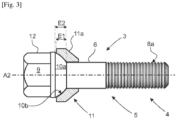
- the fixing member 3 shown comprises a screw 4 of axial extension A2 comprising a head 12 extended by a rod 5.
- the rod 5 of the screw 4 comprises a proximal section whose periphery has a smooth face 6.
- the proximal section of the rod 5 of the screw 4 slides through a bore 7 with a smooth face which the rim 1 comprises.
- the smooth face 6 of the rod 5 of the screw 4 is extended by a distal section comprising an external thread 8a which cooperates by screwing with a tapped bore 8b formed in the hub 2.
- the head 12 of the screw 4 comprises at its proximal end a male drive member 9 for rotating the screw 4, which is arranged in a polygon whose faces are formed on the periphery of the screw 4.
- the drive member 9 is extended at its distal end by a male spherical cap 10a which extends from the drive member 9 towards the smooth face 6 of the rod 5 which the male spherical cap 10a is flush with.
- the fixing member 3 also comprises a ring 11 which is threaded around the smooth face 6 of the rod 5 of the screw 4 and which axially bears against the rim 1.
- the ring 11 is formed from any metallic material, such as steel or aluminum for example.
- the ring 11 is structurally robust by preventing its deformation during the tightening of the rim 1 against the hub 2 to said setpoint threshold.
- the ring 11 has at its proximal end a proximal face shaped as a female spherical cap 10b.
- the axial extension E1 of the female spherical cap 10b of the ring 11 is at most equal to the axial extension E2 of the male spherical cap 10a formed at the distal end of the drive member 9. This makes it possible to avoid the drive member 9 being covered by the ring 11 and thus to facilitate the rotational maneuvering of the screw 4 by an operator via a male drive member 9.
- the ring 11 has at its distal end a distal face of conical conformation 11a - more specifically of truncated conical conformation.
- a small radial clearance is provided between the ring 11 and the rod 5 of screw 4 by allowing it to move relative to the ring 11 held stationary, in order to promote the centering of screw 4 inside hub 2 without affecting the firm support of the ring 11 against rim 1.
- the generatrix G1 of the conical conformation face 11a of the ring 11 is oriented substantially parallel to the generatrix G2 of the female spherical cap 10b that the ring 11 comprises.
- the conical conformation face 11a of the ring 11 is at least partly housed inside a cell 11b which the rim 1 comprises.
- the cell 11a has a conical conformation complementary to that of the ring 11, so that the conical conformation face 11a of the ring 11 firmly bears axially against the rim 1 when it is tightened against the hub 2.
- any possible centering defect of the screw 4 relative to the hub 2 is spontaneously corrected by floating of the head 12 of the screw 4 inside the ring 11, until the effective tightening S1 of the rim 1 against the hub 2 is reached to said setpoint threshold.
- the non-deformable ring 11 axially bears against the rim 1 via the conical-span fitting provided between them. Relative mobility between the ring 11 and the rim 1 is thus prohibited to avoid a variation in the coefficient of friction between the ring 11 and the rim 1 when the vehicle is moving.
- the materials from which the ring 11 and the rim 1 are respectively made can be chosen indifferently from one another, which makes it possible to control the coefficient of friction between them.
- Such localized elastic deformation by crushing of the rim 1 by the rings 11 does not affect the extent of the contact surfaces between the rings 11 and the rim 1, nor the centering inside the hub 2 of the screws 4 which are mounted to move in a ball joint relative to the ring 11.
- Such elastic deformation of the rim 1 makes it possible to complete an elastic extension of the screws 4 placed under axial stress when tightening the rim against the hub, to reinforce a firm support of the threads of the screws 4 against those of the tapped bores 8b formed in the hub 2. This finally makes it possible to avoid loosening of the screws 4 as a result of a robust support of the rings 11 against the rim 1, and this without affecting the centering of the screws 4 inside the hub 2.
- the sizing and/or geometry of the fixing member 3 makes it possible to best adjust its size both diametrically and axially. This facilitates the adaptation of the member fixing 3 according to the arrangement and/or the dimensioning of the rim 1 in the areas where the wheel is clamped to the vehicle and/or according to the type of screw 4 equipping the fixing member 3.
- the robustness of the ring 11 and the limitation of the tightening force S1 do not affect the maintenance in conformation of the ring 11 tightened between the head 12 of the screw 4 and the rim 1, and makes it possible to reduce the axial stresses supported by the screw 4 without risk of loosening.
- the tightening of the rim 1 against the hub 2 by all of the fixing members 3 is uniform, the tightening carried out via the screws 4 of each of the fixing members to said setpoint threshold being reproducible by an operator for each of the fixing members 3.
Landscapes
- Engineering & Computer Science (AREA)
- General Engineering & Computer Science (AREA)
- Mechanical Engineering (AREA)
- Connection Of Plates (AREA)
- Mounting Of Bearings Or Others (AREA)
- Braking Arrangements (AREA)
Claims (10)
- Befestigungselement (3) zum Festklemmen (S1) einer Radfelge (1) auf einer Nabe (2) eines Kraftfahrzeugs, wobei das Befestigungselement (3) mit im Wesentlichen axialer Ausdehnung (A2) eine Schraube (4) umfasst, die mit einem Kopf (12) zur axialen Abstützung gegen einen Ring (11) versehen ist, der um eine glatte Fläche (6) eines Schaftes (5) der Schraube (4) herum geschoben ist, wobei die glatte Fläche axial durch ein Außengewinde (8a) des Schaftes (5) der Schraube (4) verlängert ist, das sich an seinem distalen Ende erstreckt Gegenüberliegend zu dem Ring (11), der auf einer seiner Flächen eine teilweise sphärische Form und auf der anderen seiner Flächen eine konische Form aufweist, dadurch gekennzeichnet, dass die distale Fläche des Kopfes (12) der Schrauben (4) in einer sphärischen Kappe (10a) angeordnet ist, die durch Ineingriffnahme mit einer komplementär geformten sphärischen Kappe (10b) zusammenwirkt, die der Ring (11) auf seiner proximalen Seite aufweist, wobei die konische Formfläche (11a) des Rings (11) auf seiner distalen Seite in Form eines D-Organs ausgebildet ist Schachtelung mit konischer Reichweite.
- Befestigungselement (3) nach Anspruch 1, dadurch gekennzeichnet, dass- die Kugelkalotte (10a) des Schraubenkopfes (12) (4) eine männliche Kugelkalotte ist, die mit der Kugelkalotte (10b) des Ringes (11) zusammenwirkt, der eine weibliche Kugelkalotte ist, und- die konische Formfläche (11a) des Ringes (11) ist am Umfang der distalen Seite des Ringes (11) als Steckerteil ausgebildet.
- Befestigungselement (3) nach einem der vorhergehenden Ansprüche, dadurch gekennzeichnet, dass das Material des Rings (11) ein metallisches Material ist, das unabhängig aus irgendeinem metallischen Material ausgewählt ist.
- Befestigungselement (3) nach einem der vorhergehenden Ansprüche, dadurch gekennzeichnet, dass die Mantellinie (G1) der konischen Formfläche (11a) des Rings (11) im Wesentlichen parallel zur Mantellinie (G2) der Kugelkalotte (10b) an der proximalen Fläche des Rings (11) ausgerichtet ist.
- Befestigungselement (3) nach einem der vorhergehenden Ansprüche, dadurch gekennzeichnet, dass die axiale Erstreckung (E1) der Kugelkalotte (10b), die der Ring (11) aufweist, höchstens gleich der axialen Erstreckung (E2) der Kugelkalotte (10a) ist, die der Kopf (12) der Schrauben (4) aufweist.
- Befestigungselement (3) nach einem der Ansprüche 2 bis 5, dadurch gekennzeichnet, dass die männliche Kugelkappe (10a), die der Kopf (12) der Schrauben (4) aufweist, axial zu ihrem proximalen Ende hin durch ein männliches Antriebsorgan (9) verlängert ist, dass die Schraube (4) in Drehung versetzt.
- Befestigungselement (3) nach Anspruch 2 oder einem der Ansprüche 3 bis 6 in Abhängigkeit von Anspruch 2, dadurch gekennzeichnet, dass das proximale Ende der Kugelkappe (10a), die der Schraubenkopf (12) aufweist, mit der glatten Fläche (6) des Schraubenschaftes (5) (4) bündig ist, um den der Ring (11) geschoben ist.
- Kraftfahrzeug mit Rädern, die jeweils an den jeweiligen Naben (2) über eine Vielzahl von Befestigungselementen (3) befestigt sind, die winkelmäßig um die Drehachse der Nabe (2) verteilt sind, wobei die Befestigungselemente (3) jeweils eine Schraube (4) aufweisen, um die ein Ring (11) geschoben ist, der sich axial gegen eine Felge (1) des Rades abstützt, wobei die jeweiligen Schrauben (4) der Befestigungselemente (3) die Felge (1) über Bohrungen (7), die sie aufweist, durchqueren und an der Nabe (2) durch Anlegen der Ringe (11) angeschraubt sind Felge (1) durch axiales Klemmen (S1), dadurch gekennzeichnet, dass die Befestigungsorgane (3) jeweils mit einem Befestigungsorgan (3) übereinstimmen, das unter einen der Ansprüche 1 bis 7 fällt.
- Kraftfahrzeug nach Anspruch 8, dadurch gekennzeichnet, dass die Kugelkappen (10a), die die Köpfe (12) der Schrauben (4) der Befestigungsorgane (3) aufweisen, zumindest teilweise innerhalb der Kugelkappen (10b) der Ringe (11) angeordnet sind, wobei die konischen Formflächen (11a), die die Ringe (11) aufweisen, durch Einstecken in entsprechende Zellen (11b), die die Felge (1) aufweist, aufgenommen sind und die zumindest eine komplementäre konische Formgebung aufweisen die konische Form (11a) des Ringes (11).
- Kraftfahrzeug nach einem der Ansprüche 8 und 9, dadurch gekennzeichnet, dass das Material der Felge ein metallisches Material ist, das unabhängig aus irgendeinem metallischen Material ausgewählt ist.
Applications Claiming Priority (2)
| Application Number | Priority Date | Filing Date | Title |
|---|---|---|---|
| FR2100987A FR3119342B1 (fr) | 2021-02-02 | 2021-02-02 | Organe de fixation d'une roue en application axiale contre le moyeu d'un essieu de vehicule automobile |
| PCT/FR2022/050005 WO2022167734A1 (fr) | 2021-02-02 | 2022-01-04 | Organe de fixation d'une roue en application axiale contre le moyeu d'un essieu de vehicule automobile |
Publications (2)
| Publication Number | Publication Date |
|---|---|
| EP4288671A1 EP4288671A1 (de) | 2023-12-13 |
| EP4288671B1 true EP4288671B1 (de) | 2025-01-01 |
Family
ID=74860271
Family Applications (1)
| Application Number | Title | Priority Date | Filing Date |
|---|---|---|---|
| EP22703010.3A Active EP4288671B1 (de) | 2021-02-02 | 2022-01-04 | Element zur axialen befestigung eines rades an der nabe einer kraftfahrzeugachse |
Country Status (3)
| Country | Link |
|---|---|
| EP (1) | EP4288671B1 (de) |
| FR (1) | FR3119342B1 (de) |
| WO (1) | WO2022167734A1 (de) |
Family Cites Families (7)
| Publication number | Priority date | Publication date | Assignee | Title |
|---|---|---|---|---|
| US2844409A (en) * | 1953-06-04 | 1958-07-22 | Budd Co | Wheel mounting means |
| NL135521C (de) * | 1967-10-17 | |||
| FR2100987A1 (de) | 1970-08-03 | 1972-03-31 | Perier Jean Pierre | |
| FR2210515B1 (de) * | 1972-12-20 | 1976-06-04 | Amil | |
| DE20317196U1 (de) | 2003-11-05 | 2004-01-15 | A. Agrati S.P.A., Veduggio Con Colzano | Radschraubenanordnung für PKW oder sonstige Fahrzeuge |
| DE102010038067B4 (de) * | 2010-10-08 | 2014-07-17 | Wolfgang Weiss | Formschlussverbindung mit Ausgleich von Lagefehlern |
| JP6681312B2 (ja) * | 2016-10-28 | 2020-04-15 | 本田技研工業株式会社 | 車両用ホイール |
-
2021
- 2021-02-02 FR FR2100987A patent/FR3119342B1/fr active Active
-
2022
- 2022-01-04 EP EP22703010.3A patent/EP4288671B1/de active Active
- 2022-01-04 WO PCT/FR2022/050005 patent/WO2022167734A1/fr not_active Ceased
Also Published As
| Publication number | Publication date |
|---|---|
| EP4288671A1 (de) | 2023-12-13 |
| WO2022167734A1 (fr) | 2022-08-11 |
| FR3119342A1 (fr) | 2022-08-05 |
| FR3119342B1 (fr) | 2022-12-16 |
Similar Documents
| Publication | Publication Date | Title |
|---|---|---|
| FR2690208A1 (fr) | Ecrou, notamment écrou pour roue. | |
| FR2952853A1 (fr) | Roue composite, notamment pour un cycle, et procede de fabrication d'une telle roue | |
| EP2052877B1 (de) | Spannungsreduzierungssystem für Radnaben | |
| EP4288671B1 (de) | Element zur axialen befestigung eines rades an der nabe einer kraftfahrzeugachse | |
| EP0430743A1 (de) | Ringförmige Notlaufeinrichtung | |
| US20060145531A1 (en) | Wheel fixing device particularly for go-karts or similar vehicles | |
| EP0170085B1 (de) | Sicherheitsfelge mit axialem Blockierhump und mit genannter Felge versehene Luftreifenfelgenanordnung | |
| FR3094049A1 (fr) | Rotule sphérique | |
| EP4093985B1 (de) | Drehanordnung, insbesondere zur führung eines kraftfahrzeugrades | |
| CA3101578A1 (fr) | Ensemble jante et extenseur flexible pour ensemble roulant | |
| FR2791404A1 (fr) | Vis a serrage calibre, son procede de fabrication et systeme de raccordement electrique incorporant une telle vis | |
| EP3243670B1 (de) | Rad eines luftfahrzeugs | |
| EP0190968B1 (de) | Deformierbares Rad | |
| EP4001676B1 (de) | Bremsmutter und entsprechende befestigung | |
| EP1551648A1 (de) | Aus zwei montierten konstruktionen bestehende radfelge | |
| EP4437244B1 (de) | Bremssystem für schienenfahrzeug mit klotzbremsen und schienenfahrzeug, das mit dem system ausgestattet ist | |
| EP2608320B1 (de) | Verbindungsvorrichtung eines Kabelschuhs und Verbindungskit eines Kabelschuhs | |
| EP0521785B1 (de) | Monoblock Bremsscheibe, insbesondere für Schienenfahrzeug, und entsprechendes Rad | |
| CA3084485C (en) | Wheel retention system | |
| FR3147141A1 (fr) | Procédé d’assemblage d’un ensemble de roulement de roue | |
| FR3160742A1 (fr) | Ensemble de support | |
| FR3146306A1 (fr) | Pièce de retenue d’un ou plusieurs éléments d’assemblage rotatifs, notamment pour roue de train d’atterrissage d’aéronef | |
| EP2267323A2 (de) | Wälzlager | |
| FR3034476A1 (fr) | Plaque de matage perfectionnee pour assemblage par vis | |
| WO2002006064A1 (fr) | Palier a roulement, notamment pour roues non motrices de vehicule automobile |
Legal Events
| Date | Code | Title | Description |
|---|---|---|---|
| STAA | Information on the status of an ep patent application or granted ep patent |
Free format text: STATUS: UNKNOWN |
|
| STAA | Information on the status of an ep patent application or granted ep patent |
Free format text: STATUS: THE INTERNATIONAL PUBLICATION HAS BEEN MADE |
|
| PUAI | Public reference made under article 153(3) epc to a published international application that has entered the european phase |
Free format text: ORIGINAL CODE: 0009012 |
|
| STAA | Information on the status of an ep patent application or granted ep patent |
Free format text: STATUS: REQUEST FOR EXAMINATION WAS MADE |
|
| 17P | Request for examination filed |
Effective date: 20230727 |
|
| AK | Designated contracting states |
Kind code of ref document: A1 Designated state(s): AL AT BE BG CH CY CZ DE DK EE ES FI FR GB GR HR HU IE IS IT LI LT LU LV MC MK MT NL NO PL PT RO RS SE SI SK SM TR |
|
| DAV | Request for validation of the european patent (deleted) | ||
| DAX | Request for extension of the european patent (deleted) | ||
| GRAP | Despatch of communication of intention to grant a patent |
Free format text: ORIGINAL CODE: EPIDOSNIGR1 |
|
| STAA | Information on the status of an ep patent application or granted ep patent |
Free format text: STATUS: GRANT OF PATENT IS INTENDED |
|
| INTG | Intention to grant announced |
Effective date: 20240902 |
|
| RIN1 | Information on inventor provided before grant (corrected) |
Inventor name: PERRIER, ALEXANDRE Inventor name: DELCHER, CHRISTOPHE Inventor name: LE GUYADER, GAEL Inventor name: BELON, PIERRE GILLES Inventor name: PEREIRA, ALEXANDRE |
|
| GRAS | Grant fee paid |
Free format text: ORIGINAL CODE: EPIDOSNIGR3 |
|
| GRAA | (expected) grant |
Free format text: ORIGINAL CODE: 0009210 |
|
| STAA | Information on the status of an ep patent application or granted ep patent |
Free format text: STATUS: THE PATENT HAS BEEN GRANTED |
|
| REG | Reference to a national code |
Ref country code: DE Ref legal event code: R084 Ref document number: 602022009359 Country of ref document: DE |
|
| AK | Designated contracting states |
Kind code of ref document: B1 Designated state(s): AL AT BE BG CH CY CZ DE DK EE ES FI FR GB GR HR HU IE IS IT LI LT LU LV MC MK MT NL NO PL PT RO RS SE SI SK SM TR |
|
| REG | Reference to a national code |
Ref country code: GB Ref legal event code: FG4D Free format text: NOT ENGLISH |
|
| REG | Reference to a national code |
Ref country code: CH Ref legal event code: EP |
|
| REG | Reference to a national code |
Ref country code: DE Ref legal event code: R096 Ref document number: 602022009359 Country of ref document: DE |
|
| REG | Reference to a national code |
Ref country code: IE Ref legal event code: FG4D Free format text: LANGUAGE OF EP DOCUMENT: FRENCH |
|
| PGFP | Annual fee paid to national office [announced via postgrant information from national office to epo] |
Ref country code: AT Payment date: 20250417 Year of fee payment: 4 |
|
| REG | Reference to a national code |
Ref country code: LT Ref legal event code: MG9D |
|
| REG | Reference to a national code |
Ref country code: NL Ref legal event code: MP Effective date: 20250101 |
|
| REG | Reference to a national code |
Ref country code: AT Ref legal event code: MK05 Ref document number: 1756519 Country of ref document: AT Kind code of ref document: T Effective date: 20250101 |
|
| PG25 | Lapsed in a contracting state [announced via postgrant information from national office to epo] |
Ref country code: NL Free format text: LAPSE BECAUSE OF FAILURE TO SUBMIT A TRANSLATION OF THE DESCRIPTION OR TO PAY THE FEE WITHIN THE PRESCRIBED TIME-LIMIT Effective date: 20250101 |
|
| PG25 | Lapsed in a contracting state [announced via postgrant information from national office to epo] |
Ref country code: FI Free format text: LAPSE BECAUSE OF FAILURE TO SUBMIT A TRANSLATION OF THE DESCRIPTION OR TO PAY THE FEE WITHIN THE PRESCRIBED TIME-LIMIT Effective date: 20250101 |
|
| PG25 | Lapsed in a contracting state [announced via postgrant information from national office to epo] |
Ref country code: PL Free format text: LAPSE BECAUSE OF FAILURE TO SUBMIT A TRANSLATION OF THE DESCRIPTION OR TO PAY THE FEE WITHIN THE PRESCRIBED TIME-LIMIT Effective date: 20250101 |
|
| PG25 | Lapsed in a contracting state [announced via postgrant information from national office to epo] |
Ref country code: ES Free format text: LAPSE BECAUSE OF FAILURE TO SUBMIT A TRANSLATION OF THE DESCRIPTION OR TO PAY THE FEE WITHIN THE PRESCRIBED TIME-LIMIT Effective date: 20250101 |
|
| PG25 | Lapsed in a contracting state [announced via postgrant information from national office to epo] |
Ref country code: IS Free format text: LAPSE BECAUSE OF FAILURE TO SUBMIT A TRANSLATION OF THE DESCRIPTION OR TO PAY THE FEE WITHIN THE PRESCRIBED TIME-LIMIT Effective date: 20250501 Ref country code: NO Free format text: LAPSE BECAUSE OF FAILURE TO SUBMIT A TRANSLATION OF THE DESCRIPTION OR TO PAY THE FEE WITHIN THE PRESCRIBED TIME-LIMIT Effective date: 20250401 |
|
| PG25 | Lapsed in a contracting state [announced via postgrant information from national office to epo] |
Ref country code: HR Free format text: LAPSE BECAUSE OF FAILURE TO SUBMIT A TRANSLATION OF THE DESCRIPTION OR TO PAY THE FEE WITHIN THE PRESCRIBED TIME-LIMIT Effective date: 20250101 |
|
| PG25 | Lapsed in a contracting state [announced via postgrant information from national office to epo] |
Ref country code: PT Free format text: LAPSE BECAUSE OF FAILURE TO SUBMIT A TRANSLATION OF THE DESCRIPTION OR TO PAY THE FEE WITHIN THE PRESCRIBED TIME-LIMIT Effective date: 20250502 Ref country code: LV Free format text: LAPSE BECAUSE OF FAILURE TO SUBMIT A TRANSLATION OF THE DESCRIPTION OR TO PAY THE FEE WITHIN THE PRESCRIBED TIME-LIMIT Effective date: 20250101 |
|
| PG25 | Lapsed in a contracting state [announced via postgrant information from national office to epo] |
Ref country code: BG Free format text: LAPSE BECAUSE OF FAILURE TO SUBMIT A TRANSLATION OF THE DESCRIPTION OR TO PAY THE FEE WITHIN THE PRESCRIBED TIME-LIMIT Effective date: 20250101 Ref country code: GR Free format text: LAPSE BECAUSE OF FAILURE TO SUBMIT A TRANSLATION OF THE DESCRIPTION OR TO PAY THE FEE WITHIN THE PRESCRIBED TIME-LIMIT Effective date: 20250402 |
|
| PG25 | Lapsed in a contracting state [announced via postgrant information from national office to epo] |
Ref country code: AT Free format text: LAPSE BECAUSE OF FAILURE TO SUBMIT A TRANSLATION OF THE DESCRIPTION OR TO PAY THE FEE WITHIN THE PRESCRIBED TIME-LIMIT Effective date: 20250101 |
|
| PG25 | Lapsed in a contracting state [announced via postgrant information from national office to epo] |
Ref country code: CZ Free format text: LAPSE BECAUSE OF FAILURE TO SUBMIT A TRANSLATION OF THE DESCRIPTION OR TO PAY THE FEE WITHIN THE PRESCRIBED TIME-LIMIT Effective date: 20250101 |
|
| REG | Reference to a national code |
Ref country code: CH Ref legal event code: PL |
|
| PG25 | Lapsed in a contracting state [announced via postgrant information from national office to epo] |
Ref country code: SE Free format text: LAPSE BECAUSE OF FAILURE TO SUBMIT A TRANSLATION OF THE DESCRIPTION OR TO PAY THE FEE WITHIN THE PRESCRIBED TIME-LIMIT Effective date: 20250101 |
|
| PG25 | Lapsed in a contracting state [announced via postgrant information from national office to epo] |
Ref country code: LU Free format text: LAPSE BECAUSE OF NON-PAYMENT OF DUE FEES Effective date: 20250104 |
|
| REG | Reference to a national code |
Ref country code: DE Ref legal event code: R097 Ref document number: 602022009359 Country of ref document: DE |
|
| PG25 | Lapsed in a contracting state [announced via postgrant information from national office to epo] |
Ref country code: SM Free format text: LAPSE BECAUSE OF FAILURE TO SUBMIT A TRANSLATION OF THE DESCRIPTION OR TO PAY THE FEE WITHIN THE PRESCRIBED TIME-LIMIT Effective date: 20250101 |
|
| PG25 | Lapsed in a contracting state [announced via postgrant information from national office to epo] |
Ref country code: DK Free format text: LAPSE BECAUSE OF FAILURE TO SUBMIT A TRANSLATION OF THE DESCRIPTION OR TO PAY THE FEE WITHIN THE PRESCRIBED TIME-LIMIT Effective date: 20250101 |
|
| PG25 | Lapsed in a contracting state [announced via postgrant information from national office to epo] |
Ref country code: MC Free format text: LAPSE BECAUSE OF FAILURE TO SUBMIT A TRANSLATION OF THE DESCRIPTION OR TO PAY THE FEE WITHIN THE PRESCRIBED TIME-LIMIT Effective date: 20250101 |
|
| PG25 | Lapsed in a contracting state [announced via postgrant information from national office to epo] |
Ref country code: BE Free format text: LAPSE BECAUSE OF NON-PAYMENT OF DUE FEES Effective date: 20250131 |
|
| PG25 | Lapsed in a contracting state [announced via postgrant information from national office to epo] |
Ref country code: CH Free format text: LAPSE BECAUSE OF NON-PAYMENT OF DUE FEES Effective date: 20250131 |
|
| PG25 | Lapsed in a contracting state [announced via postgrant information from national office to epo] |
Ref country code: EE Free format text: LAPSE BECAUSE OF FAILURE TO SUBMIT A TRANSLATION OF THE DESCRIPTION OR TO PAY THE FEE WITHIN THE PRESCRIBED TIME-LIMIT Effective date: 20250101 |
|
| REG | Reference to a national code |
Ref country code: BE Ref legal event code: MM Effective date: 20250131 |
|
| PG25 | Lapsed in a contracting state [announced via postgrant information from national office to epo] |
Ref country code: RO Free format text: LAPSE BECAUSE OF FAILURE TO SUBMIT A TRANSLATION OF THE DESCRIPTION OR TO PAY THE FEE WITHIN THE PRESCRIBED TIME-LIMIT Effective date: 20250101 |
|
| PG25 | Lapsed in a contracting state [announced via postgrant information from national office to epo] |
Ref country code: SK Free format text: LAPSE BECAUSE OF FAILURE TO SUBMIT A TRANSLATION OF THE DESCRIPTION OR TO PAY THE FEE WITHIN THE PRESCRIBED TIME-LIMIT Effective date: 20250101 |
|
| PLBE | No opposition filed within time limit |
Free format text: ORIGINAL CODE: 0009261 |
|
| STAA | Information on the status of an ep patent application or granted ep patent |
Free format text: STATUS: NO OPPOSITION FILED WITHIN TIME LIMIT |
|
| 26N | No opposition filed |
Effective date: 20251002 |
|
| PGFP | Annual fee paid to national office [announced via postgrant information from national office to epo] |
Ref country code: FR Payment date: 20251217 Year of fee payment: 5 |
|
| PG25 | Lapsed in a contracting state [announced via postgrant information from national office to epo] |
Ref country code: IE Free format text: LAPSE BECAUSE OF NON-PAYMENT OF DUE FEES Effective date: 20250104 |
|
| PGFP | Annual fee paid to national office [announced via postgrant information from national office to epo] |
Ref country code: DE Payment date: 20251217 Year of fee payment: 5 |
|
| PGFP | Annual fee paid to national office [announced via postgrant information from national office to epo] |
Ref country code: IT Payment date: 20260107 Year of fee payment: 5 |