EP4288361B1 - Verriegelungsvorrichtung und fahrerloses transportfahrzeug - Google Patents
Verriegelungsvorrichtung und fahrerloses transportfahrzeug Download PDFInfo
- Publication number
- EP4288361B1 EP4288361B1 EP22700870.3A EP22700870A EP4288361B1 EP 4288361 B1 EP4288361 B1 EP 4288361B1 EP 22700870 A EP22700870 A EP 22700870A EP 4288361 B1 EP4288361 B1 EP 4288361B1
- Authority
- EP
- European Patent Office
- Prior art keywords
- snap
- locking
- hook
- locking device
- blocking
- Prior art date
- Legal status (The legal status is an assumption and is not a legal conclusion. Google has not performed a legal analysis and makes no representation as to the accuracy of the status listed.)
- Active
Links
Images


Classifications
-
- B—PERFORMING OPERATIONS; TRANSPORTING
- B65—CONVEYING; PACKING; STORING; HANDLING THIN OR FILAMENTARY MATERIAL
- B65G—TRANSPORT OR STORAGE DEVICES, e.g. CONVEYORS FOR LOADING OR TIPPING, SHOP CONVEYOR SYSTEMS OR PNEUMATIC TUBE CONVEYORS
- B65G69/00—Auxiliary measures taken, or devices used, in connection with loading or unloading
- B65G69/003—Restraining movement of a vehicle at a loading station using means not being part of the vehicle
-
- B—PERFORMING OPERATIONS; TRANSPORTING
- B60—VEHICLES IN GENERAL
- B60D—VEHICLE CONNECTIONS
- B60D1/00—Traction couplings; Hitches; Draw-gear; Towing devices
- B60D1/01—Traction couplings or hitches characterised by their type
- B60D1/04—Hook or hook-and-hasp couplings
-
- B—PERFORMING OPERATIONS; TRANSPORTING
- B60—VEHICLES IN GENERAL
- B60D—VEHICLE CONNECTIONS
- B60D1/00—Traction couplings; Hitches; Draw-gear; Towing devices
- B60D2001/001—Traction couplings; Hitches; Draw-gear; Towing devices specially adapted for use on vehicles other than cars
- B60D2001/005—Traction couplings; Hitches; Draw-gear; Towing devices specially adapted for use on vehicles other than cars for carts, scooters or the like
Definitions
- the invention relates to a locking device for locking to a movable frame, comprising a base, a latching hook which can be pivoted relative to the base about a pivot axis running in a transverse direction between a locking position and an unlocking position, and a latching device for blocking the latching hook on the base in the locking position.
- the invention also relates to a driverless transport vehicle which comprises at least one locking device according to the invention.
- Driverless transport vehicles can be used in various facilities, such as supermarkets, industrial halls, logistics centers, hospitals and production plants.
- the driverless transport vehicles are used, for example, to transport objects, such as movable frames, within the respective facility.
- Such a frame has one or more support surfaces arranged one above the other for holding goods.
- Such a frame also has several rotating rollers which are arranged underneath the support surfaces and which are in contact with a floor on which the frame stands. The frame is movable by means of the rollers.
- the frame can be locked to the driverless transport vehicle using a locking device. If the frame is located at a stationary workstation where, for example, goods on it are removed, the frame can be locked to the said workstation using a locking device to prevent the frame from rolling away accidentally.
- the device comprises a carriage which is arranged to be displaceable on a rail.
- the rail has locking recesses for receiving a locking element.
- a device for securing containers and pallets on transport surfaces is known.
- channels are embedded in the transport surface, and A narrow frame is attached above it.
- the base frames of the containers can be attached to the frame.
- a locking device for a vehicle comprises a pivotable locking hook, which fixes a bolt of the vehicle in a locking position.
- the locking device comprises a locking hook and a contactless sensor for detecting an element of the vehicle.
- a method and a device for coupling a transport vehicle to a movable load are known.
- a locking element of the transport vehicle engages in a locking opening of the load.
- the locking device comprises a pivotable locking hook, which fixes an element of the vehicle in a locking position.
- the invention is based on the object of creating a locking device for locking with a movable frame, which can be used at a stationary workstation as well as on a driverless transport vehicle.
- the invention is also based on the object of creating a corresponding driverless transport vehicle.
- the object is achieved by a locking device with the features specified in claim 1.
- Advantageous embodiments and further developments are the subject of the subclaims.
- the object is also achieved by a driverless transport vehicle with the features specified in claim 12.
- the latching hook has a latching section and a control section, and the latching section has a catch contour for Accommodating a profile of a frame in the locking position.
- the latching hook is arranged such that when a locking force is applied to the control section, the latching hook is pivoted from the unlocking position into the locking position, and the latching device is designed and arranged such that the latching hook is automatically blocked by the latching device when the locking position is reached, the latching device moving into a blocking position.
- the rack can be locked using the locking device at a stationary workstation, where, for example, goods on it are removed, to prevent the rack from rolling away accidentally.
- the rack is automatically locked by pushing it onto the locking device; additional manual operation of the locking device is not required for locking, which saves process time.
- the locking section has a run-on surface which is arranged on a side of the catch contour facing away from the control section and which runs inclined to a longitudinal direction and inclined to a vertical direction.
- the run-on surface allows a frame to be pushed in even when the locking hook is in the locking position.
- the profile of the frame slides along the run-on surface over the catch contour, falls behind the catch contour and is thus received by the catch contour.
- the latching hook and the latching device are arranged in such a way that when the latching device is moved out of the blocking position, when the latching device blocks the latching hook in the locking position, and in the absence of a locking force on the control section, the latching hook is pivoted from the locking position into the unlocking position.
- the frame can thus be unlocked by simply moving the latching device out of the blocking position.
- the latching section extends at least approximately at right angles to the control section. This enables a compact design of the locking device.
- a pivoting movement of the latching hook from the locking position to the unlocking position is carried out by a Gravity acting on the locking hook, particularly on the locking section. Additional components such as springs or drives are therefore not required and the structure of the locking device is simplified.
- a pivoting movement of the locking hook from the locking position to the unlocking position is carried out by a spring force acting on the locking hook.
- the locking position can thus be used flexibly in different orientations. The orientation is not dependent on the direction of gravity.
- control section has a control contour which interacts with the locking device in such a way that during a pivoting movement of the locking hook from the unlocking position to the locking position, the locking device is moved out of the blocking position.
- control contour interacts with the locking device in such a way that when the locking position is reached, the locking device is moved into the blocking position. The frame is thereby automatically locked by the locking device.
- control section has a bore which interacts with the locking device in such a way that when the locking hook is in the locking position and the locking device is in the blocking position, a locking pin of the locking device engages in the bore.
- the locking pin engaging in the bore ensures that the locking hook is blocked in the locking position.
- the locking device can be moved from the blocking position and into the blocking position in the transverse direction, and the bore extends in the transverse direction.
- the frame can thus be unlocked by a simple translational movement of the locking device.
- the locking device can be moved out of the blocking position against a spring force.
- the locking device is thus automatically moved into the blocking position by the spring force.
- the locking hook has a sensor for detecting a profile of a frame.
- the sensor allows detection of whether a frame is locked with the locking device and a corresponding message to be sent to a control unit.
- a driverless transport vehicle comprises a drive device, an electrical energy storage device for supplying the drive device and a control unit for controlling the drive device and at least one locking device according to the invention.
- the drive device comprises, for example, an electric motor, a transmission and drive wheels.
- the frame can be locked to the driverless transport vehicle by means of the locking device.
- Figure 1 shows a perspective view of a movable frame 50 locked with a locking device 10.
- the frame 50 is located on a flat floor which extends at right angles to a vertical direction Z.
- a transverse direction Y extends at right angles to the vertical direction Z.
- a longitudinal direction X extends at right angles to the vertical direction Z and at right angles to the transverse direction Y.
- the frame 50 comprises a support surface which extends at right angles to the vertical direction Z.
- the support surface serves to accommodate goods to be transported, for example boxes or cartons.
- the support surface is formed from several profiles 55 which are connected to one another, for example welded.
- the profiles 55, in particular profiles 55 which are arranged on the edge of the support surface, have a rectangular or square cross-section.
- the frame 50 further comprises four rotatable rollers 51.
- the rollers 51 are arranged below the wings and are in contact with the ground.
- the rollers 51 can each be rotated about a rotation axis which runs at right angles to the vertical direction Z.
- the rollers 51 can also each be pivoted about a pivot axis which runs in the vertical direction Z.
- the rotation axis and the pivot axis of such a roller 51 do not intersect in the present case, but are spaced apart from one another.
- the frame 50 can be moved on the ground by means of the rollers 51.
- a locking device 10 is attached to a column 60 which extends from the floor in the vertical direction Z.
- the locking device 10 comprises a base 40, a latching hook 20 and a latching device 30.
- the base 40 of the locking device 10 is fastened to the column 60.
- the latching hook 20 of the locking device 10 interacts with a profile 55 of the frame 50.
- a locking device 10 it is also conceivable to attach a locking device 10 to a wall or a vehicle. It is also conceivable to attach a locking device 10 to a frame 50 so that several frames 50 can be locked together. In particular, it is conceivable to attach a locking device 10 to a driverless transport vehicle. Frames can thus be transported by the driverless transport vehicle within a system.
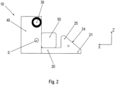
- Figure 2 shows a side view of the locking device 10 in the locking position.
- the latching hook 20 can be pivoted relative to the base 40 about a pivot axis S running in a transverse direction Y between the locking position shown here and an unlocking position.
- the latching device 30 is in the blocking position and blocks the latching hook 20 on the base 40 in the locking position.
- the locking hook 20 has a locking section 21 and a control section 22 which is concealed here.
- the locking section 21 has a catch contour 25 in which the profile 55 of the frame 50 is received in the locking position.
- the locking section 21 extends at least approximately at right angles to the control section 22. In the locking position, the locking section 21 extends in the longitudinal direction X and the control section 22 extends in the vertical direction Z.
- the pivoting movement of the latching hook 20 from the locking position to the unlocking position is carried out in the present case by a force of gravity acting on the latching hook 20, in particular on the latching section 21.
- a force of gravity acting on the latching hook 20 in particular on the latching section 21.
- the locking section 21 has a run-on surface 24 which runs inclined to a longitudinal direction X and inclined to a vertical direction Z.
- the run-on surface 24 is arranged on a side of the catch contour 25 facing away from the control section 22.
- Figure 3 shows a side view of the locking device 10 in the unlocking position.
- the locking hook 20 is in comparison to the Figure 1 shown position relative to the base 40 about the pivot axis S.
- the profile 55 of the frame 50 is released in the unlocking position.
- the locking device 30 is in the blocking position. However, the locking device 30 does not block the locking hook 20 in the unlocking position.
- the control section 22 has a bore 27 which interacts with a locking pin 32 of the locking device 30, which is hidden here.
- the bore 27 runs in the transverse direction Y.
- the locking device 30 with the locking pin 32 can be moved in the transverse direction Y.
- the locking device 30 can be moved from the blocking position against a spring force. In the absence of a counterforce, the locking device 30 is moved into the blocking position by the said spring force.
- the locking hook 20 is in the locking position and the locking device 30 is in the blocking position, the locking pin 32 engages in the bore 27.
- the control section 22 has a control contour 26.
- the control contour 26 is a surface that extends from the bore 27 to an edge of the control section 22 and that runs at an angle to the transverse direction Y.
- the locking pin 32 slides along the control contour 26. This moves the locking device 30 out of the blocking position.
- the locking pin 32 falls into the bore 27. This moves the locking device 30 into the blocking position and the locking hook 20 is automatically blocked in the locking position by the locking device 30.
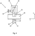
- Figure 4 shows a plan view of the locking device 10 in the unlocking position.
- the locking device 30 is in the blocking position and the locking bolt 32 projects into a cavity in the base 40 behind the control section 22 of the locking hook 20.
- the locking device 30 can be moved out of the blocking position against a spring force by pulling in the transverse direction Y.
Landscapes
- Engineering & Computer Science (AREA)
- Mechanical Engineering (AREA)
- Lock And Its Accessories (AREA)
- Handcart (AREA)
Description
- Die Erfindung betrifft eine Verriegelungsvorrichtung zur Verriegelung mit einem beweglichen Gestell, umfassend eine Basis einen Rasthaken, welcher relativ zu der Basis um eine in eine Querrichtung verlaufende Schwenkachse zwischen einer Verriegelungsstellung und einer Entriegelungsstellung schwenkbar ist, und eine Rastvorrichtung zur Blockierung des Rasthakens an der Basis in der Verriegelungsstellung. Die Erfindung betrifft auch ein fahrerloses Transportfahrzeug, welches mindestens eine erfindungsgemäße Verriegelungsvorrichtung umfasst.
- In verschiedenen Anlagen, beispielsweise in Supermärkten, Industriehallen, Logistikzentren, Krankenhäusern und Produktionswerken, sind fahrerlose Transportfahrzeuge einsetzbar. Die fahrerlosen Transportfahrzeuge dienen beispielsweise zum Transport von Gegenständen, beispielsweise von beweglichen Gestellen, innerhalb der jeweiligen Anlage.
- Ein solches Gestell weist eine oder mehrere übereinander angeordnete Tragflächen zur Aufnahme von Waren auf. Ein solches Gestell weist auch mehrere drehbare Rollen auf, welche unterhalb der Tragflächen angeordnet sind, und welche in Kontakt mit einem Boden sind, auf welchem das Gestell steht. Mittels der Rollen ist das Gestell beweglich.
- Zum Transport des Gestells mittels eines fahrerlosen Transportfahrzeugs kann das Gestell mittels einer Verriegelungsvorrichtung mit dem fahrerlosen Transportfahrzeug verriegelt werden. Wenn das Gestell sich an einem stationären Arbeitsplatz befindet, wo beispielsweise darauf befindliche Waren entnommen werden, kann das Gestell mittels einer Verriegelungsvorrichtung an dem besagten Arbeitsplatz verriegelt werden um ein ungewolltes Wegrollen des Gestells zu verhindern.
- Aus der
DE 203 02 929 U1 ist eine Vorrichtung zur Sicherung von Ladegütern bekannt. Die Vorrichtung umfasst einen Schlitten, der an einer Schiene verschiebbar angeordnet ist. Die Schiene weist Rastausnehmungen zur Aufnahme eines Rastelements auf. - Aus der
DE 10 2012 021 450 A1 ist eine Vorrichtung zur Sicherung von Behältern und Paletten auf Transportflächen bekannt. Dabei sind in der Transportfläche Rinnen eingelassen, und darüber ist ein schmales Gestell befestigt. Grundrahmen der Behälter sind an dem Gestell befestigbar. - Aus der
US 4,127,856 A ist eine Rastvorrichtung für ein Fahrzeug bekannt. Die Rastvorrichtung umfasst einen schwenkbaren Rasthaken, welcher in einer Verriegelungsstellung einen Bolzen des Fahrzeugs fixiert. - Aus der
US 6,033,174 A ist eine Halteeinrichtung für ein Fahrzeug bekannt. Die Rastvorrichtung umfasst einen Rasthaken und einen berührungslosen Sensor zur Erfassung eines Elements des Fahrzeugs. - Aus der
WO 2016/195596 A1 sind ein Verfahren und eine Vorrichtung zur Kopplung eines Transportfahrzeugs mit einer beweglichen Last bekannt. Dabei greift ein Verriegelungselement des Transportfahrzeugs in eine Verriegelungsöffnung der Last ein. - Aus der
US 2015/0210487 A1 ist eine Rastvorrichtung für ein Fahrzeug bekannt. Die Rastvorrichtung umfasst einen schwenkbaren Rasthaken, welcher in einer Verriegelungsstellung ein Element des Fahrzeugs fixiert. - Der Erfindung liegt die Aufgabe zugrunde, eine Verriegelungsvorrichtung zur Verriegelung mit einem beweglichen Gestell zu schaffen, welche an einem stationären Arbeitsplatz ebenso wie an einem fahrerlosen Transportfahrzeug einsetzbar ist. Der Erfindung liegt auch die Aufgabe zugrunde, ein entsprechendes fahrerloses Transportfahrzeug zu schaffen.
- Die Aufgabe wird durch eine Verriegelungsvorrichtung mit den in Anspruch 1 angegebenen Merkmalen gelöst. Vorteilhafte Ausgestaltungen und Weiterbildungen sind Gegenstand der Unteransprüche. Die Aufgabe wird auch durch ein fahrerloses Transportfahrzeug mit den in Anspruch 12 angegebenen Merkmalen gelöst.
- Eine erfindungsgemäße Verriegelungsvorrichtung zur Verriegelung mit einem beweglichen Gestell umfasst eine Basis, einen Rasthaken, welcher relativ zu der Basis um eine in eine Querrichtung verlaufende Schwenkachse zwischen einer Verriegelungsstellung und einer Entriegelungsstellung schwenkbar ist, und eine Rastvorrichtung zur Blockierung des Rasthakens an der Basis in der Verriegelungsstellung. Der Rasthaken weist einen Rastabschnitt und einen Steuerabschnitt auf, und der Rastabschnitt weist eine Fangkontur zur Aufnahme eines Profils eines Gestells in der Verriegelungsstellung auf. Der Rasthaken ist derart angeordnet, dass bei Aufbringen einer Verriegelungskraft auf den Steuerabschnitt der Rasthaken von der Entriegelungsstellung in die Verriegelungsstellung geschwenkt wird, und die Rastvorrichtung ist derart ausgestaltet und angeordnet, dass der Rasthaken bei Erreichen der Verriegelungsstellung automatisch durch die Rastvorrichtung blockiert wird, wobei die Rastvorrichtung in eine Blockierposition gelangt.
- Das Gestell ist mittels der Verriegelungsvorrichtung an einem stationären Arbeitsplatz, wo beispielsweise darauf befindliche Waren entnommen werden, verriegelbar um ein ungewolltes Wegrollen des Gestells zu verhindern. Dabei wird das Gestell durch Schieben auf die Verriegelungsvorrichtung automatisch verriegelt, eine zusätzliche manuelle Betätigung der Verriegelungsvorrichtung ist zum Verriegeln nicht erforderlich, wodurch Prozesszeit eingespart wird.
- Erfindungsgemäß weist der Rastabschnitt eine Auflauffläche auf, welche auf einer dem Steuerabschnitt abgewandten Seite der Fangkontur angeordnet ist, und die geneigt zu einer Längsrichtung und geneigt zu einer Vertikalrichtung verläuft. Die Auflauffläche gestattet ein Einschieben eines Gestells auch, wenn der Rasthaken sich in der Verriegelungsstellung befindet. Das Profil des Gestells gleitet dabei entlang der Auflauffläche über die Fangkontur, fällt hinter der Fangkontur ein und wird somit von der Fangkontur aufgenommen.
- Gemäß einer vorteilhaften Ausgestaltung der Erfindung sind der Rasthaken und die Rastvorrichtung derart angeordnet, dass bei einer Bewegung der Rastvorrichtung aus der Blockierposition heraus, wenn die Rastvorrichtung den Rasthaken in der Verriegelungsstellung blockiert, und bei Abwesenheit einer Verriegelungskraft auf den Steuerabschnitt der Rasthaken von der Verriegelungsstellung in die Entriegelungsstellung geschwenkt wird. Das Gestell ist somit durch einfaches Bewegen der Rastvorrichtung aus der Blockierposition heraus entriegelbar.
- Gemäß einer bevorzugten Ausgestaltung der Erfindung erstreckt der Rastabschnitt sich zumindest annähernd rechtwinklig zu dem Steuerabschnitt. Dies ermöglicht eine kompakte Bauweise der Verriegelungsvorrichtung.
- Gemäß einer vorteilhaften Ausgestaltung der Erfindung erfolgt eine Schwenkbewegung des Rasthakens von der Verriegelungsstellung in die Entriegelungsstellung durch eine auf den Rasthaken, insbesondere auf den Rastabschnitt, wirkende Schwerkraft. Zusätzliche Komponente, wie beispielsweise Federn oder Antriebe, sind somit nicht erforderlich, und der Aufbau der Verriegelungsvorrichtung ist vereinfacht.
- Gemäß einer weiteren vorteilhaften Ausgestaltung der Erfindung erfolgt eine Schwenkbewegung des Rasthakens von der Verriegelungsstellung in die Entriegelungsstellung durch eine auf den Rasthaken wirkende Federkraft. Die Verriegelungsstellung ist somit flexibel in verschiedenen Ausrichtungen einsetzbar. Die Ausrichtung ist nicht von der Richtung der Schwerkraft abhängig.
- Gemäß einer vorteilhaften Weiterbildung der Erfindung weist der Steuerabschnitt eine Steuerkontur auf, welche derart mit der Rastvorrichtung zusammenwirkt, dass während einer Schwenkbewegung des Rasthakens von der Entriegelungsstellung in die Verriegelungsstellung die Rastvorrichtung aus der Blockierposition heraus bewegt wird.
- Vorzugsweise wirkt die Steuerkontur dabei derart mit der Rastvorrichtung zusammen, dass bei Erreichen der Verriegelungsstellung die Rastvorrichtung in die Blockierposition hinein bewegt wird. Dadurch wird das Gestell von der Verriegelungsvorrichtung automatisch verriegelt.
- Gemäß einer bevorzugten Ausgestaltung der Erfindung weist der Steuerabschnitt eine Bohrung auf, welche derart mit der Rastvorrichtung zusammenwirkt, dass bei in der Verriegelungsstellung befindlichem Rasthaken und in der Blockierposition befindlicher Rastvorrichtung ein Rastbolzen der Rastvorrichtung in die Bohrung eingreift. Der in die Bohrung eingreifende Rastbolzen stellt die Blockierung des Rasthakens in der Verriegelungsstellung sicher.
- Gemäß einer vorteilhaften Ausgestaltung der Erfindung ist die Rastvorrichtung aus der Blockierposition heraus und in die Blockierposition hinein in die Querrichtung bewegbar, und die Bohrung verläuft in die Querrichtung. Das Gestell ist somit durch eine einfache translatorische Bewegung der Rastvorrichtung entriegelbar.
- Gemäß einer bevorzugten Ausgestaltung der Erfindung ist die Rastvorrichtung aus der Blockierposition heraus entgegen einer Federkraft bewegbar. Die Rastvorrichtung wird somit von der Federkraft automatisch in die Blockierposition bewegt.
- Gemäß einer vorteilhaften Weiterbildung der Erfindung weist der Rasthaken einen Sensor zur Detektion eines Profils eines Gestells auf. Der Sensor gestattet eine Erkennung, ob ein Gestell mit der Verriegelungsvorrichtung verriegelt ist, und eine entsprechende Meldung an ein Steuergerät.
- Ein erfindungsgemäßes fahrerloses Transportfahrzeug umfasst eine Antriebseinrichtung, einen elektrischen Energiespeicher zur Versorgung der Antriebseinrichtung sowie eine Steuereinheit zur Steuerung der Antriebseinrichtung und mindestens eine erfindungsgemäße Verriegelungsvorrichtung. Die Antriebseinrichtung umfasst beispielsweise einen Elektromotor, ein Getriebe und Antriebsräder. Zum Transport eines Gestells ist das Gestell mittels der Verriegelungsvorrichtung mit dem fahrerlosen Transportfahrzeug verriegelbar.
- Die Erfindung ist nicht auf die Merkmalskombination der Ansprüche beschränkt. Für den Fachmann ergeben sich weitere sinnvolle Kombinationsmöglichkeiten von Ansprüchen und/oder einzelnen Anspruchsmerkmalen und/oder Merkmalen der Beschreibung und/oder der Figuren, insbesondere aus der Aufgabenstellung und/oder der sich durch Vergleich mit dem Stand der Technik stellenden Aufgabe.
- Die Erfindung wird nun anhand von Abbildungen näher erläutert. Die Erfindung ist nicht auf die in den Abbildungen dargestellten Ausführungsbeispiele beschränkt. Die Abbildungen stellen den Gegenstand der Erfindung nur schematisch dar. Es zeigen:
- Figur 1:
- eine perspektivische Darstellung eines mit einer Verriegelungsvorrichtung verriegelten beweglichen Gestells,
- Figur 2:
- eine Seitenansicht der Verriegelungsvorrichtung in Verriegelungsstellung,
- Figur 3:
- eine Seitenansicht der Verriegelungsvorrichtung in Entriegelungsstellung und
- Figur 4:
- eine Draufsicht auf die Verriegelungsvorrichtung in Entriegelungsstellung.
-
Figur 1 zeigt eine perspektivische Darstellung eines mit einer Verriegelungsvorrichtung 10 verriegelten beweglichen Gestells 50. Das Gestell 50 befindet sich auf einem ebenen Boden, welcher sich rechtwinklig zu einer Vertikalrichtung Z erstreckt. Eine Querrichtung Y erstreckt sich rechtwinklig zu der Vertikalrichtung Z. Eine Längsrichtung X erstreckt sich rechtwinklig zu der Vertikalrichtung Z und rechtwinklig zu der Querrichtung Y. - Das Gestell 50 und umfasst eine Tragfläche, welche sich rechtwinklig zu der Vertikalrichtung Z erstreckt. Die Tragfläche dient zur Aufnahme von zu transportierenden Waren, beispielsweise Kisten oder Kartons. Die Tragfläche ist aus mehreren Profilen 55 gebildet, die miteinander verbunden, beispielsweise verschweißt, sind. Die Profile 55, insbesondere Profile 55, die am Rand der Tragfläche angeordnet sind, weisen einen rechteckigen oder quadratischen Querschnitt auf.
- Das Gestell 50 umfasst ferner vier drehbare Rollen 51. Die Rollen 51 sind unterhalb der Tragflächen angeordnet und stehen in Kontakt mit dem Boden. Die Rollen 51 sind jeweils um eine Drehachse drehbar, welche rechtwinklig zu der Vertikalrichtung Z verläuft. Die Rollen 51 sind zusätzlich jeweils um eine Schwenkachse schwenkbar, welche in Vertikalrichtung Z verläuft. Die Drehachse und die Schwenkachse einer solche Rolle 51 schneiden sich vorliegend nicht, sondern sind voneinander beabstandet. Mittels der Rollen 51 ist das Gestell 50 auf dem Boden beweglich.
- An einer Säule 60, die sich von dem Boden in Vertikalrichtung Z erstreckt, ist eine Verriegelungsvorrichtung 10 angebracht. Die Verriegelungsvorrichtung 10 umfasst eine Basis 40, einen Rasthaken 20 und eine Rastvorrichtung 30. Die Basis 40 der Verriegelungsvorrichtung 10 ist an der Säule 60 befestigt. Zur Verriegelung des Gestells 50 wirkt der Rasthaken 20 der Verriegelungsvorrichtung 10 mit einem Profil 55 des Gestells 50 zusammen.
- Es ist auch denkbar, eine Verriegelungsvorrichtung 10 an einer Wand oder einem Fahrzeug anzubringen. Auch ist es denkbar, eine Verriegelungsvorrichtung 10 an einem Gestell 50 anzubringen, so dass mehrere Gestelle 50 miteinander verriegelbar sind. Insbesondere ist es denkbar, eine Verriegelungsvorrichtung 10 an einem fahrerlosen Transportfahrzeug anzubringen. Somit sind Gestelle von dem fahrerlosen Transportfahrzeug innerhalb einer Anlage transportierbar.
-
Figur 2 zeigt eine Seitenansicht der Verriegelungsvorrichtung 10 in Verriegelungsstellung. Der Rasthaken 20 ist relativ zu der Basis 40 um eine in eine Querrichtung Y verlaufende Schwenkachse S zwischen der hier gezeigten Verriegelungsstellung und einer Entriegelungsstellung schwenkbar. Die Rastvorrichtung 30 befindet sich in der Blockierposition und blockiert den Rasthaken 20 an der Basis 40 in der Verriegelungsstellung. - Der Rasthaken 20 weist einen Rastabschnitt 21 und einen hier verdeckten Steuerabschnitt 22 auf. Der Rastabschnitt 21 weist eine Fangkontur 25 auf, in welcher das Profil 55 des Gestells 50 in der Verriegelungsstellung aufgenommen ist. Der Rastabschnitt 21 erstreckt sich zumindest annähernd rechtwinklig zu dem Steuerabschnitt 22. In der Verriegelungsstellung erstreckt sich der Rastabschnitt 21 in Längsrichtung X, und der Steuerabschnitt 22 erstreckt sich in Vertikalrichtung Z.
- Die Schwenkbewegung des Rasthakens 20 von der Verriegelungsstellung in die Entriegelungsstellung erfolgt vorliegend durch eine auf den Rasthaken 20, insbesondere auf den Rastabschnitt 21, wirkende Schwerkraft. Alternativ oder zusätzlich ist es denkbar, eine Feder vorzusehen, so dass die Schwenkbewegung des Rasthakens 20 von der Verriegelungsstellung in die Entriegelungsstellung durch eine auf den Rasthaken 20 wirkende Federkraft erfolgt.
- Der Rastabschnitt 21 weist eine Auflauffläche 24 auf, die geneigt zu einer Längsrichtung X und geneigt zu einer Vertikalrichtung Z verläuft. Die Auflauffläche 24 ist auf einer dem Steuerabschnitt 22 abgewandten Seite der Fangkontur 25 angeordnet.
-
Figur 3 zeigt eine Seitenansicht der Verriegelungsvorrichtung 10 in Entriegelungsstellung. Der Rasthaken 20 ist dabei im Vergleich zu der inFigur 1 dargestellten Stellung relativ zu der Basis 40 um die Schwenkachse S geschwenkt. Das Profil 55 des Gestells 50 ist in der Entriegelungsstellung freigegeben. Die Rastvorrichtung 30 befindet sich in der Blockierposition. Die Rastvorrichtung 30 blockiert den Rasthaken 20 jedoch nicht in der Entriegelungsstellung. - Wenn das Profil 55 des Gestells 50 gegen den Steuerabschnitt 22 des Rasthaken 20 gedrückt wird, so wird dadurch eine Verriegelungskraft auf den Steuerabschnitt 22 aufgebracht. Die Verriegelungskraft wirkt in Längsrichtung X in Richtung auf die Basis zu. Bei Aufbringen der Verriegelungskraft wird der Rasthaken 20 von der Entriegelungsstellung in die Verriegelungsstellung geschwenkt.
- Der Steuerabschnitt 22 weist eine Bohrung 27 auf, welche mit einem hier verdeckten Rastbolzen 32 der Rastvorrichtung 30 zusammenwirkt. Die Bohrung 27 verläuft in die Querrichtung Y. Die Rastvorrichtung 30 mit dem Rastbolzen 32 ist in die Querrichtung Y bewegbar. Die Rastvorrichtung 30 ist aus der Blockierposition heraus entgegen einer Federkraft bewegbar. Bei Abwesenheit einer Gegenkraft wird die Rastvorrichtung 30 von der besagten Federkraft in die Blockierposition hinein bewegt. Bei in der Verriegelungsstellung befindlichem Rasthaken 20 und in der Blockierposition befindlicher Rastvorrichtung 30 greift der Rastbolzen 32 in die Bohrung 27 ein.
- Der Steuerabschnitt 22 weist eine Steuerkontur 26 auf. Die Steuerkontur 26 ist eine Fläche, die sich von der Bohrung 27 bis zu einem Rand des Steuerabschnitts 22 erstreckt, und die geneigt zu der Querrichtung Y verläuft. Während einer Schwenkbewegung des Rasthakens 20 von der Entriegelungsstellung in die Verriegelungsstellung gleitet der Rastbolzen 32 entlang der Steuerkontur 26. Dadurch wird die Rastvorrichtung 30 aus der Blockierposition heraus bewegt. Bei Erreichen der Verriegelungsstellung fällt der Rastbolzen 32 in die Bohrung 27 ein. Dadurch gelangt die Rastvorrichtung 30 in die Blockierposition, und der Rasthaken 20 wird in der Verriegelungsstellung automatisch durch die Rastvorrichtung 30 blockiert.
-
Figur 4 zeigt eine Draufsicht auf die Verriegelungsvorrichtung 10 in Entriegelungsstellung. Die Rastvorrichtung 30 befindet sich in der Blockierposition, und der Rastbolzen 32 ragt in einen Hohlraum der Basis 40 hinter dem Steuerabschnitt 22 des Rasthakens 20 hinein. Wie bereits erwähnt, ist die Rastvorrichtung 30 durch Ziehen in Querrichtung Y aus der Blockierposition heraus entgegen einer Federkraft bewegbar. - Bei einer solchen Bewegung der Rastvorrichtung 30 aus der Blockierposition heraus wird der Rastbolzen 32 aus der Bohrung 27 heraus gezogen. Bei Abwesenheit einer Verriegelungskraft auf den Steuerabschnitt 22 wird der Rasthaken 20 dabei von der Verriegelungsstellung in die Entriegelungsstellung geschwenkt.
-
- 10
- Verriegelungsvorrichtung
- 20
- Rasthaken
- 21
- Rastabschnitt
- 22
- Steuerabschnitt
- 24
- Auflauffläche
- 25
- Fangkontur
- 26
- Steuerkontur
- 27
- Bohrung
- 30
- Rastvorrichtung
- 32
- Rastbolzen
- 40
- Basis
- 50
- Gestell
- 51
- Rolle
- 55
- Profil
- 60
- Säule
- S
- Schwenkachse
- X
- Längsrichtung
- Y
- Querrichtung
- Z
- Vertikalrichtung
Claims (12)
- Verriegelungsvorrichtung (10) zur Verriegelung mit einem beweglichen Gestell (50), umfassendeine Basis (40),einen Rasthaken (20), welcher relativ zu der Basis (40) um eine in eine Querrichtung (Y) verlaufende Schwenkachse (S)zwischen einer Verriegelungsstellung und einer Entriegelungsstellung schwenkbar ist, undeine Rastvorrichtung (30) zur Blockierung des Rasthakens (20) an der Basis (40) in der Verriegelungsstellung,wobeider Rasthaken (20) einen Rastabschnitt (21) und einen Steuerabschnitt (22) aufweist,der Rastabschnitt (21) eine Fangkontur (25) zur Aufnahme eines Profils (55) eines Gestells (50) in der Verriegelungsstellung aufweist,der Rasthaken (20) derart angeordnet ist, dass bei Aufbringen einer Verriegelungskraft auf den Steuerabschnitt (22) der Rasthaken (20) von der Entriegelungsstellung in die Verriegelungsstellung geschwenkt wird, unddie Rastvorrichtung (30) derart ausgestaltet und angeordnet ist, dass der Rasthaken (20) bei Erreichen der Verriegelungsstellung automatisch durch die Rastvorrichtung (30) blockiert wird, wobei die Rastvorrichtung (30) in eine Blockierposition gelangt, dadurch gekennzeichnet, dassder Rastabschnitt (21) eine Auflauffläche (24) aufweist, welche auf einer dem Steuerabschnitt (22) abgewandten Seite der Fangkontur (25) angeordnet ist, und die geneigt zu einer Längsrichtung (X) und geneigt zu einer Vertikalrichtung (Z) verläuft.
- Verriegelungsvorrichtung (10) nach Anspruch 1,
dadurch gekennzeichnet, dassder Rasthaken (20) und die Rastvorrichtung (30) derart angeordnet sind, dass bei einer Bewegung der Rastvorrichtung (30) aus der Blockierposition heraus, undbei Abwesenheit einer Verriegelungskraft auf den Steuerabschnitt (22),der Rasthaken (20) von der Verriegelungsstellung in die Entriegelungsstellung geschwenkt wird. - Verriegelungsvorrichtung (10) nach einem der vorangegangenen Ansprüche,
dadurch gekennzeichnet, dass
der Rastabschnitt (21) sich zumindest annähernd rechtwinklig zu dem Steuerabschnitt (22) erstreckt. - Verriegelungsvorrichtung (10) nach einem der vorangegangenen Ansprüche,
dadurch gekennzeichnet, dass
eine Schwenkbewegung des Rasthakens (20) von der Verriegelungsstellung in die Entriegelungsstellung durch eine auf den Rasthaken (20), insbesondere auf den Rastabschnitt (21), wirkende Schwerkraft erfolgt. - Verriegelungsvorrichtung (10) nach einem der vorangegangenen Ansprüche,
dadurch gekennzeichnet, dass
eine Schwenkbewegung des Rasthakens (20) von der Verriegelungsstellung in die Entriegelungsstellung durch eine auf den Rasthaken (20) wirkende Federkraft erfolgt. - Verriegelungsvorrichtung (10) nach einem der vorangegangenen Ansprüche,
dadurch gekennzeichnet, dass
der Steuerabschnitt (22) eine Steuerkontur (26) aufweist, welche derart mit der Rastvorrichtung (30) zusammenwirkt, dass während einer Schwenkbewegung des Rasthakens (20) von der Entriegelungsstellung in die Verriegelungsstellung die Rastvorrichtung (30) aus der Blockierposition heraus bewegt wird. - Verriegelungsvorrichtung (10) Anspruch 6,
dadurch gekennzeichnet, dass
die Steuerkontur (26) derart mit der Rastvorrichtung (30) zusammenwirkt, dass bei Erreichen der Verriegelungsstellung die Rastvorrichtung (30) in die Blockierposition hinein bewegt wird. - Verriegelungsvorrichtung (10) nach einem der vorangegangenen Ansprüche,
dadurch gekennzeichnet, dass
der Steuerabschnitt (22) eine Bohrung (27) aufweist, welche derart mit der Rastvorrichtung (30) zusammenwirkt, dass bei in der Verriegelungsstellung befindlichem Rasthaken (20) und in der Blockierposition befindlicher Rastvorrichtung (30) ein Rastbolzen (32) der Rastvorrichtung (30) in die Bohrung (27) eingreift. - Verriegelungsvorrichtung (10) nach Anspruch 8,
dadurch gekennzeichnet, dass
die Rastvorrichtung (30) in die Querrichtung (Y) bewegbar ist, und dass die Bohrung (27) in die Querrichtung (Y) verläuft. - Verriegelungsvorrichtung (10) nach einem der vorangegangenen Ansprüche,
dadurch gekennzeichnet, dass
die Rastvorrichtung (30) aus der Blockierposition heraus entgegen einer Federkraft bewegbar ist. - Verriegelungsvorrichtung (10) nach einem der vorangegangenen Ansprüche,
dadurch gekennzeichnet, dass
der Rasthaken (20) einen Sensor zur Detektion eines Profils (55) eines Gestells (50) aufweist. - Fahrerloses Transportfahrzeug, umfassend
eine Antriebseinrichtung, einen elektrischen Energiespeicher zur Versorgung der Antriebseinrichtung sowie eine Steuereinheit zur Steuerung der Antriebseinrichtung und mindestens eine Verriegelungsvorrichtung (10) nach einem der vorangegangenen Ansprüche.
Applications Claiming Priority (2)
| Application Number | Priority Date | Filing Date | Title |
|---|---|---|---|
| DE102021000494.9A DE102021000494B3 (de) | 2021-02-02 | 2021-02-02 | Verriegelungsvorrichtung und fahrerloses Transportfahrzeug |
| PCT/EP2022/025016 WO2022167146A1 (de) | 2021-02-02 | 2022-01-18 | Verriegelungsvorrichtung und fahrerloses transportfahrzeug |
Publications (2)
| Publication Number | Publication Date |
|---|---|
| EP4288361A1 EP4288361A1 (de) | 2023-12-13 |
| EP4288361B1 true EP4288361B1 (de) | 2024-10-16 |
Family
ID=80050889
Family Applications (1)
| Application Number | Title | Priority Date | Filing Date |
|---|---|---|---|
| EP22700870.3A Active EP4288361B1 (de) | 2021-02-02 | 2022-01-18 | Verriegelungsvorrichtung und fahrerloses transportfahrzeug |
Country Status (5)
| Country | Link |
|---|---|
| US (1) | US20240308793A1 (de) |
| EP (1) | EP4288361B1 (de) |
| CN (1) | CN116710373A (de) |
| DE (2) | DE102021000494B3 (de) |
| WO (1) | WO2022167146A1 (de) |
Families Citing this family (1)
| Publication number | Priority date | Publication date | Assignee | Title |
|---|---|---|---|---|
| WO2025081239A1 (en) * | 2023-10-20 | 2025-04-24 | The Dynamic Engineering Solution Pty Ltd | Load securing device |
Citations (5)
| Publication number | Priority date | Publication date | Assignee | Title |
|---|---|---|---|---|
| US4887954A (en) * | 1989-03-09 | 1989-12-19 | Air-Lec Industries, Inc. | Vehicle restraint |
| EP0473910A1 (de) * | 1990-09-04 | 1992-03-11 | Caterpillar Industrial Inc. | Palettenpositionierung |
| US20130017045A1 (en) * | 2011-07-13 | 2013-01-17 | Andrew Brooks | Vehicle restraints with stop mechanisms |
| US20190329993A1 (en) * | 2018-04-27 | 2019-10-31 | Denis Gleason | Trailer Restraint With Auxiliary Locking Mechanism |
| US20190367300A1 (en) * | 2018-05-29 | 2019-12-05 | Rite-Hite Holding Corporation | Vehicle restraints with a barrier having rotational and translational motion |
Family Cites Families (14)
| Publication number | Priority date | Publication date | Assignee | Title |
|---|---|---|---|---|
| US4127856A (en) * | 1977-04-11 | 1978-11-28 | Bickel Gary G | Vehicle-dock latching apparatus |
| DE3921314C1 (de) * | 1989-06-29 | 1990-08-23 | Daimler-Benz Aktiengesellschaft, 7000 Stuttgart, De | |
| US6033174A (en) * | 1997-08-29 | 2000-03-07 | United Dominion Ind., Inc. | Vehicle restraint sensing system |
| DE20302929U1 (de) | 2003-02-21 | 2003-07-17 | ANCRA Jungfalk GmbH & Co. KG, 78234 Engen | Vorrichtung zur Sicherung von Ladegütern |
| US8596949B2 (en) * | 2009-12-29 | 2013-12-03 | Nordock, Inc. | Constant torque vehicle restraint |
| DE102012021450B4 (de) | 2012-10-31 | 2022-09-15 | Techlnpro Gmbh | Vorrichtung zur Sicherung von Behältern und Paletten auf Transportflächen, insbesondere auf Fahrzeugböden |
| US9586771B2 (en) * | 2014-01-29 | 2017-03-07 | Rite-Hite Holding Corporation | Vehicle restraints with underside catches |
| SG10201504272TA (en) * | 2015-05-29 | 2016-12-29 | Ctrlworks Pte Ltd | Method and Apparatus for Coupling an Automated Load Transporter to a Moveable Load |
| US20170066607A1 (en) * | 2015-09-08 | 2017-03-09 | Multi-Fab Products, Llc | Engaged biased hook |
| DE102016221829B4 (de) * | 2016-11-08 | 2025-02-20 | Audi Ag | Energieversorgungsfahrzeug zum Versorgen eines elektrisch antreibbaren Kraftfahrzeugs mit elektrischer Energie |
| CN108312792B (zh) * | 2018-01-26 | 2024-07-23 | 苏州博众智能机器人有限公司 | 自锁料车运输机器人 |
| CN208039506U (zh) * | 2018-03-30 | 2018-11-02 | 承德宏兴制冷设备有限公司 | 一种锁扣和保温板 |
| CN210635138U (zh) * | 2019-08-19 | 2020-05-29 | 徐州徐工环境技术有限公司 | 垃圾压缩装置 |
| CN112209035B (zh) * | 2020-09-28 | 2022-03-11 | 中国人民解放军陆军工程大学 | 车载式烧毁炉远端送料系统及方法 |
-
2021
- 2021-02-02 DE DE102021000494.9A patent/DE102021000494B3/de active Active
-
2022
- 2022-01-18 US US18/275,488 patent/US20240308793A1/en active Pending
- 2022-01-18 CN CN202280008738.5A patent/CN116710373A/zh active Pending
- 2022-01-18 DE DE102022000171.3A patent/DE102022000171A1/de active Pending
- 2022-01-18 WO PCT/EP2022/025016 patent/WO2022167146A1/de not_active Ceased
- 2022-01-18 EP EP22700870.3A patent/EP4288361B1/de active Active
Patent Citations (5)
| Publication number | Priority date | Publication date | Assignee | Title |
|---|---|---|---|---|
| US4887954A (en) * | 1989-03-09 | 1989-12-19 | Air-Lec Industries, Inc. | Vehicle restraint |
| EP0473910A1 (de) * | 1990-09-04 | 1992-03-11 | Caterpillar Industrial Inc. | Palettenpositionierung |
| US20130017045A1 (en) * | 2011-07-13 | 2013-01-17 | Andrew Brooks | Vehicle restraints with stop mechanisms |
| US20190329993A1 (en) * | 2018-04-27 | 2019-10-31 | Denis Gleason | Trailer Restraint With Auxiliary Locking Mechanism |
| US20190367300A1 (en) * | 2018-05-29 | 2019-12-05 | Rite-Hite Holding Corporation | Vehicle restraints with a barrier having rotational and translational motion |
Also Published As
| Publication number | Publication date |
|---|---|
| US20240308793A1 (en) | 2024-09-19 |
| DE102022000171A1 (de) | 2022-08-04 |
| CN116710373A (zh) | 2023-09-05 |
| DE102021000494B3 (de) | 2022-03-31 |
| WO2022167146A1 (de) | 2022-08-11 |
| EP4288361A1 (de) | 2023-12-13 |
Similar Documents
| Publication | Publication Date | Title |
|---|---|---|
| AT511623A2 (de) | Regallagersystem | |
| EP4288361B1 (de) | Verriegelungsvorrichtung und fahrerloses transportfahrzeug | |
| DE29803921U1 (de) | Stapelsäule zur Aufnahme einer Vielzahl von flächigen Werkstücken | |
| EP1473224B1 (de) | Fördereinrichtung an einem Cargo-Deck eines Flugzeugs | |
| EP2766284A1 (de) | Bewegungsvorrichtung für transporteinheiten | |
| WO2002100718A1 (de) | Verfahren und vorrichtung zum positionieren von frachtbehältern auf einer ladefläche | |
| DE102018220377B4 (de) | Fahrzeug, Fahrzeugsystem und Verfahren zum Betreiben eines Fahrzeugsystems | |
| EP2505453A2 (de) | Transportwagen | |
| DE102004040161B4 (de) | Vorrichtung zum Beschichten von Gegenständen | |
| DE102016201962B4 (de) | Verfahren und Vorrichtung zur Förderung eines Regallager-Transportfahrzeugs | |
| EP2261129B1 (de) | Palette zum Transportieren von Gegenständen mittels eines Gabelstaplers | |
| EP2392523A1 (de) | Regal mit Zentrierungsrollen | |
| DE102016106147A1 (de) | an einer Zimmerdecke aufhängbare Schrank-Vorrichtung | |
| EP3772395A1 (de) | Arbeitsplatz mit rollenstrecke sowie be- und entladewagen | |
| AT509458B1 (de) | Regallager mit regalbediengerät | |
| EP4326662A1 (de) | Vorrichtung zum halten von gegenständen | |
| EP1340667B1 (de) | Vorrichtung zum Aufnehmen und/oder Transportieren wenigstens eines Funktionsteils einer technischen Einrichtung | |
| DE102005039355B4 (de) | Vorrichtung und Verfahren zum Befestigen von Wechselbehältern an Trägerfahrzeugen | |
| EP3201065A2 (de) | Plattformwagen | |
| DE3009081C2 (de) | Lenkrollen-Feststellvorrichtung an Müllcontainern o.dgl. | |
| DE102010055348B4 (de) | Überführungsvorrichtung für Transportwagen und Förderanlage mit einer solchen | |
| EP2710935B1 (de) | Vorrichtung zur Führung eines Verschlussriegels und Behälter, insbesondere Briefkasten oder Paketbox | |
| EP1136339B1 (de) | Seitliche Ladegutsicherung für Schienenfahrzeuge | |
| DE102017200864B4 (de) | Hubvorrichtung zum Heben von Komponenten | |
| DE10307598A1 (de) | Vorrichtung zur Sicherung von rollenförmigen Ladegütern, insbesondere liegenden Papierrollen auf dem Ladeboden von Fahrzeugen, insbesondere Eisenbahngüterwagen |
Legal Events
| Date | Code | Title | Description |
|---|---|---|---|
| STAA | Information on the status of an ep patent application or granted ep patent |
Free format text: STATUS: UNKNOWN |
|
| STAA | Information on the status of an ep patent application or granted ep patent |
Free format text: STATUS: THE INTERNATIONAL PUBLICATION HAS BEEN MADE |
|
| PUAI | Public reference made under article 153(3) epc to a published international application that has entered the european phase |
Free format text: ORIGINAL CODE: 0009012 |
|
| STAA | Information on the status of an ep patent application or granted ep patent |
Free format text: STATUS: REQUEST FOR EXAMINATION WAS MADE |
|
| 17P | Request for examination filed |
Effective date: 20230904 |
|
| AK | Designated contracting states |
Kind code of ref document: A1 Designated state(s): AL AT BE BG CH CY CZ DE DK EE ES FI FR GB GR HR HU IE IS IT LI LT LU LV MC MK MT NL NO PL PT RO RS SE SI SK SM TR |
|
| DAV | Request for validation of the european patent (deleted) | ||
| DAX | Request for extension of the european patent (deleted) | ||
| GRAP | Despatch of communication of intention to grant a patent |
Free format text: ORIGINAL CODE: EPIDOSNIGR1 |
|
| STAA | Information on the status of an ep patent application or granted ep patent |
Free format text: STATUS: GRANT OF PATENT IS INTENDED |
|
| INTG | Intention to grant announced |
Effective date: 20240604 |
|
| GRAS | Grant fee paid |
Free format text: ORIGINAL CODE: EPIDOSNIGR3 |
|
| GRAA | (expected) grant |
Free format text: ORIGINAL CODE: 0009210 |
|
| STAA | Information on the status of an ep patent application or granted ep patent |
Free format text: STATUS: THE PATENT HAS BEEN GRANTED |
|
| AK | Designated contracting states |
Kind code of ref document: B1 Designated state(s): AL AT BE BG CH CY CZ DE DK EE ES FI FR GB GR HR HU IE IS IT LI LT LU LV MC MK MT NL NO PL PT RO RS SE SI SK SM TR |
|
| REG | Reference to a national code |
Ref country code: GB Ref legal event code: FG4D Free format text: NOT ENGLISH |
|
| REG | Reference to a national code |
Ref country code: CH Ref legal event code: EP Ref country code: DE Ref legal event code: R096 Ref document number: 502022001921 Country of ref document: DE |
|
| REG | Reference to a national code |
Ref country code: IE Ref legal event code: FG4D Free format text: LANGUAGE OF EP DOCUMENT: GERMAN |
|
| REG | Reference to a national code |
Ref country code: LT Ref legal event code: MG9D |
|
| REG | Reference to a national code |
Ref country code: NL Ref legal event code: MP Effective date: 20241016 |
|
| PG25 | Lapsed in a contracting state [announced via postgrant information from national office to epo] |
Ref country code: NL Free format text: LAPSE BECAUSE OF FAILURE TO SUBMIT A TRANSLATION OF THE DESCRIPTION OR TO PAY THE FEE WITHIN THE PRESCRIBED TIME-LIMIT Effective date: 20241016 |
|
| PG25 | Lapsed in a contracting state [announced via postgrant information from national office to epo] |
Ref country code: NL Free format text: LAPSE BECAUSE OF FAILURE TO SUBMIT A TRANSLATION OF THE DESCRIPTION OR TO PAY THE FEE WITHIN THE PRESCRIBED TIME-LIMIT Effective date: 20241016 |
|
| PG25 | Lapsed in a contracting state [announced via postgrant information from national office to epo] |
Ref country code: HR Free format text: LAPSE BECAUSE OF FAILURE TO SUBMIT A TRANSLATION OF THE DESCRIPTION OR TO PAY THE FEE WITHIN THE PRESCRIBED TIME-LIMIT Effective date: 20241016 Ref country code: PT Free format text: LAPSE BECAUSE OF FAILURE TO SUBMIT A TRANSLATION OF THE DESCRIPTION OR TO PAY THE FEE WITHIN THE PRESCRIBED TIME-LIMIT Effective date: 20250217 Ref country code: IS Free format text: LAPSE BECAUSE OF FAILURE TO SUBMIT A TRANSLATION OF THE DESCRIPTION OR TO PAY THE FEE WITHIN THE PRESCRIBED TIME-LIMIT Effective date: 20250216 |
|
| PG25 | Lapsed in a contracting state [announced via postgrant information from national office to epo] |
Ref country code: FI Free format text: LAPSE BECAUSE OF FAILURE TO SUBMIT A TRANSLATION OF THE DESCRIPTION OR TO PAY THE FEE WITHIN THE PRESCRIBED TIME-LIMIT Effective date: 20241016 |
|
| PG25 | Lapsed in a contracting state [announced via postgrant information from national office to epo] |
Ref country code: BG Free format text: LAPSE BECAUSE OF FAILURE TO SUBMIT A TRANSLATION OF THE DESCRIPTION OR TO PAY THE FEE WITHIN THE PRESCRIBED TIME-LIMIT Effective date: 20241016 |
|
| PG25 | Lapsed in a contracting state [announced via postgrant information from national office to epo] |
Ref country code: ES Free format text: LAPSE BECAUSE OF FAILURE TO SUBMIT A TRANSLATION OF THE DESCRIPTION OR TO PAY THE FEE WITHIN THE PRESCRIBED TIME-LIMIT Effective date: 20241016 |
|
| PG25 | Lapsed in a contracting state [announced via postgrant information from national office to epo] |
Ref country code: NO Free format text: LAPSE BECAUSE OF FAILURE TO SUBMIT A TRANSLATION OF THE DESCRIPTION OR TO PAY THE FEE WITHIN THE PRESCRIBED TIME-LIMIT Effective date: 20250116 |
|
| PG25 | Lapsed in a contracting state [announced via postgrant information from national office to epo] |
Ref country code: LV Free format text: LAPSE BECAUSE OF FAILURE TO SUBMIT A TRANSLATION OF THE DESCRIPTION OR TO PAY THE FEE WITHIN THE PRESCRIBED TIME-LIMIT Effective date: 20241016 Ref country code: GR Free format text: LAPSE BECAUSE OF FAILURE TO SUBMIT A TRANSLATION OF THE DESCRIPTION OR TO PAY THE FEE WITHIN THE PRESCRIBED TIME-LIMIT Effective date: 20250117 |
|
| PG25 | Lapsed in a contracting state [announced via postgrant information from national office to epo] |
Ref country code: PL Free format text: LAPSE BECAUSE OF FAILURE TO SUBMIT A TRANSLATION OF THE DESCRIPTION OR TO PAY THE FEE WITHIN THE PRESCRIBED TIME-LIMIT Effective date: 20241016 |
|
| PG25 | Lapsed in a contracting state [announced via postgrant information from national office to epo] |
Ref country code: RS Free format text: LAPSE BECAUSE OF FAILURE TO SUBMIT A TRANSLATION OF THE DESCRIPTION OR TO PAY THE FEE WITHIN THE PRESCRIBED TIME-LIMIT Effective date: 20250116 |
|
| PG25 | Lapsed in a contracting state [announced via postgrant information from national office to epo] |
Ref country code: SM Free format text: LAPSE BECAUSE OF FAILURE TO SUBMIT A TRANSLATION OF THE DESCRIPTION OR TO PAY THE FEE WITHIN THE PRESCRIBED TIME-LIMIT Effective date: 20241016 |
|
| PG25 | Lapsed in a contracting state [announced via postgrant information from national office to epo] |
Ref country code: DK Free format text: LAPSE BECAUSE OF FAILURE TO SUBMIT A TRANSLATION OF THE DESCRIPTION OR TO PAY THE FEE WITHIN THE PRESCRIBED TIME-LIMIT Effective date: 20241016 |
|
| REG | Reference to a national code |
Ref country code: DE Ref legal event code: R097 Ref document number: 502022001921 Country of ref document: DE |
|
| PG25 | Lapsed in a contracting state [announced via postgrant information from national office to epo] |
Ref country code: EE Free format text: LAPSE BECAUSE OF FAILURE TO SUBMIT A TRANSLATION OF THE DESCRIPTION OR TO PAY THE FEE WITHIN THE PRESCRIBED TIME-LIMIT Effective date: 20241016 |
|
| PG25 | Lapsed in a contracting state [announced via postgrant information from national office to epo] |
Ref country code: RO Free format text: LAPSE BECAUSE OF FAILURE TO SUBMIT A TRANSLATION OF THE DESCRIPTION OR TO PAY THE FEE WITHIN THE PRESCRIBED TIME-LIMIT Effective date: 20241016 |
|
| PG25 | Lapsed in a contracting state [announced via postgrant information from national office to epo] |
Ref country code: SK Free format text: LAPSE BECAUSE OF FAILURE TO SUBMIT A TRANSLATION OF THE DESCRIPTION OR TO PAY THE FEE WITHIN THE PRESCRIBED TIME-LIMIT Effective date: 20241016 |
|
| PG25 | Lapsed in a contracting state [announced via postgrant information from national office to epo] |
Ref country code: CZ Free format text: LAPSE BECAUSE OF FAILURE TO SUBMIT A TRANSLATION OF THE DESCRIPTION OR TO PAY THE FEE WITHIN THE PRESCRIBED TIME-LIMIT Effective date: 20241016 |
|
| PG25 | Lapsed in a contracting state [announced via postgrant information from national office to epo] |
Ref country code: IT Free format text: LAPSE BECAUSE OF FAILURE TO SUBMIT A TRANSLATION OF THE DESCRIPTION OR TO PAY THE FEE WITHIN THE PRESCRIBED TIME-LIMIT Effective date: 20241016 |
|
| PLBE | No opposition filed within time limit |
Free format text: ORIGINAL CODE: 0009261 |
|
| STAA | Information on the status of an ep patent application or granted ep patent |
Free format text: STATUS: NO OPPOSITION FILED WITHIN TIME LIMIT |
|
| REG | Reference to a national code |
Ref country code: CH Ref legal event code: PL |
|
| PG25 | Lapsed in a contracting state [announced via postgrant information from national office to epo] |
Ref country code: SE Free format text: LAPSE BECAUSE OF FAILURE TO SUBMIT A TRANSLATION OF THE DESCRIPTION OR TO PAY THE FEE WITHIN THE PRESCRIBED TIME-LIMIT Effective date: 20241016 |
|
| PG25 | Lapsed in a contracting state [announced via postgrant information from national office to epo] |
Ref country code: MC Free format text: LAPSE BECAUSE OF FAILURE TO SUBMIT A TRANSLATION OF THE DESCRIPTION OR TO PAY THE FEE WITHIN THE PRESCRIBED TIME-LIMIT Effective date: 20241016 Ref country code: LU Free format text: LAPSE BECAUSE OF NON-PAYMENT OF DUE FEES Effective date: 20250118 |
|
| 26N | No opposition filed |
Effective date: 20250717 |
|
| PG25 | Lapsed in a contracting state [announced via postgrant information from national office to epo] |
Ref country code: BE Free format text: LAPSE BECAUSE OF NON-PAYMENT OF DUE FEES Effective date: 20250131 |
|
| PG25 | Lapsed in a contracting state [announced via postgrant information from national office to epo] |
Ref country code: FR Free format text: LAPSE BECAUSE OF NON-PAYMENT OF DUE FEES Effective date: 20250131 |
|
| PG25 | Lapsed in a contracting state [announced via postgrant information from national office to epo] |
Ref country code: CH Free format text: LAPSE BECAUSE OF NON-PAYMENT OF DUE FEES Effective date: 20250131 |
|
| REG | Reference to a national code |
Ref country code: BE Ref legal event code: MM Effective date: 20250131 |
|
| PG25 | Lapsed in a contracting state [announced via postgrant information from national office to epo] |
Ref country code: IE Free format text: LAPSE BECAUSE OF NON-PAYMENT OF DUE FEES Effective date: 20250118 |
|
| PGFP | Annual fee paid to national office [announced via postgrant information from national office to epo] |
Ref country code: DE Payment date: 20260131 Year of fee payment: 5 |
|
| PGFP | Annual fee paid to national office [announced via postgrant information from national office to epo] |
Ref country code: AT Payment date: 20260301 Year of fee payment: 5 |