EP4288313B1 - Betätigungseinrichtung für eine bremsanlage - Google Patents
Betätigungseinrichtung für eine bremsanlage Download PDFInfo
- Publication number
- EP4288313B1 EP4288313B1 EP22702231.6A EP22702231A EP4288313B1 EP 4288313 B1 EP4288313 B1 EP 4288313B1 EP 22702231 A EP22702231 A EP 22702231A EP 4288313 B1 EP4288313 B1 EP 4288313B1
- Authority
- EP
- European Patent Office
- Prior art keywords
- drive shaft
- actuating device
- housing
- bearing
- brake cylinder
- Prior art date
- Legal status (The legal status is an assumption and is not a legal conclusion. Google has not performed a legal analysis and makes no representation as to the accuracy of the status listed.)
- Active
Links
Images
Classifications
-
- B—PERFORMING OPERATIONS; TRANSPORTING
- B60—VEHICLES IN GENERAL
- B60T—VEHICLE BRAKE CONTROL SYSTEMS OR PARTS THEREOF; BRAKE CONTROL SYSTEMS OR PARTS THEREOF, IN GENERAL; ARRANGEMENT OF BRAKING ELEMENTS ON VEHICLES IN GENERAL; PORTABLE DEVICES FOR PREVENTING UNWANTED MOVEMENT OF VEHICLES; VEHICLE MODIFICATIONS TO FACILITATE COOLING OF BRAKES
- B60T13/00—Transmitting braking action from initiating means to ultimate brake actuator with power assistance or drive; Brake systems incorporating such transmitting means, e.g. air-pressure brake systems
- B60T13/74—Transmitting braking action from initiating means to ultimate brake actuator with power assistance or drive; Brake systems incorporating such transmitting means, e.g. air-pressure brake systems with electrical assistance or drive
- B60T13/745—Transmitting braking action from initiating means to ultimate brake actuator with power assistance or drive; Brake systems incorporating such transmitting means, e.g. air-pressure brake systems with electrical assistance or drive acting on a hydraulic system, e.g. a master cylinder
-
- B—PERFORMING OPERATIONS; TRANSPORTING
- B60—VEHICLES IN GENERAL
- B60T—VEHICLE BRAKE CONTROL SYSTEMS OR PARTS THEREOF; BRAKE CONTROL SYSTEMS OR PARTS THEREOF, IN GENERAL; ARRANGEMENT OF BRAKING ELEMENTS ON VEHICLES IN GENERAL; PORTABLE DEVICES FOR PREVENTING UNWANTED MOVEMENT OF VEHICLES; VEHICLE MODIFICATIONS TO FACILITATE COOLING OF BRAKES
- B60T11/00—Transmitting braking action from initiating means to ultimate brake actuator without power assistance or drive or where such assistance or drive is irrelevant
- B60T11/10—Transmitting braking action from initiating means to ultimate brake actuator without power assistance or drive or where such assistance or drive is irrelevant transmitting by fluid means, e.g. hydraulic
- B60T11/16—Master control, e.g. master cylinders
- B60T11/18—Connection thereof to initiating means
-
- B—PERFORMING OPERATIONS; TRANSPORTING
- B60—VEHICLES IN GENERAL
- B60Y—INDEXING SCHEME RELATING TO ASPECTS CROSS-CUTTING VEHICLE TECHNOLOGY
- B60Y2410/00—Constructional features of vehicle sub-units
- B60Y2410/102—Shaft arrangements; Shaft supports, e.g. bearings
Definitions
- the invention relates to an actuating device for a brake system, with an electric motor which is designed to drive a drive shaft which is mounted so as to be rotatable about an axis of rotation, with a housing, and with a master brake cylinder which is rigidly connected to the housing, wherein at least one hydraulic piston is displaceably mounted in the master brake cylinder, and wherein the drive shaft is coupled to the hydraulic piston in such a way that the hydraulic piston is displaceable by a rotation of the drive shaft.
- the invention relates to a braking system with such an actuating device.
- a hydraulic brake system of a motor vehicle usually has several friction brake devices.
- an actuating device with a master brake cylinder is usually provided, in which at least one hydraulic piston is displaceably mounted.
- the master brake cylinder is fluidically connected to slave cylinders of the friction brake devices in such a way that the friction brake devices can be actuated by displacing the hydraulic piston.
- Electromechanical actuation devices are increasingly being used in motor vehicle construction.
- One such actuation device is, for example, published patent application WO 2017 108 228 A1
- the actuating device has an electric motor which is designed to drive a rotatably mounted drive shaft.
- the drive shaft is coupled to the hydraulic piston in such a way that the hydraulic piston can be moved by rotating the drive shaft.
- the hydraulic piston can therefore be moved by the electric motor via the drive shaft, so that the friction brake devices can ultimately be actuated by the electric motor.
- the actuating device also has a housing, with the master brake cylinder being rigidly connected to the housing.
- the electric motor is arranged outside the housing to which the master brake cylinder is rigidly connected.
- the disclosure DE 10 2016 113802 A1 deals with a power assist system including a motor having a rotor shaft, a drive pulley attached to the rotor shaft, a driven pulley, a flexible belt configured to connect the drive pulley to the driven pulley, and a ball screw assembly.
- the ball screw assembly includes a rotatable ball screw rotatable together with the driven pulley, a linear transmission screw nut surrounding the ball screw, and an anti-rotation device arranged to prevent rotation of the screw nut.
- the actuating device according to the invention with the features of claim 1 has the advantage that the actuating device is particularly compact and thus space-saving.
- the electric motor is arranged in the housing and that the rigid connection of the master brake cylinder to the housing is at least partially provided by the drive shaft.
- the electric motor is therefore arranged in the housing to which the master brake cylinder is rigidly connected. Due to the arrangement in the housing, the electric motor is protected by the housing, so that an additional motor housing can be dispensed with.
- the electric motor is preferably designed without a motor housing. In addition to saving installation space for the actuating device, this also saves costs.
- the master brake cylinder is rigidly connected to the housing or rigidly attached to the housing.
- a rigid connection between two bodies is to be understood as a connection that does not allow any relative movement of the bodies to one another.
- the rigid connection of the master brake cylinder to the housing is designed, for example, to transmit both axial forces and radial forces. If the terms "axial” and “radial” are used in the disclosure, these terms refer to the axis of rotation of the drive shaft, unless another reference for the terms is expressly disclosed.
- An axial force is therefore to be understood as a force that is aligned parallel to the axis of rotation.
- a radial force is accordingly to be understood as a force which is aligned perpendicular to the axis of rotation.
- the hydraulic piston is displaceable along a displacement axis which is aligned parallel to the axis of rotation of the drive shaft.
- the rigid connection of the housing to the master brake cylinder is at least partially provided or brought about by the drive shaft. If, for example, the master brake cylinder is subjected to an axial force, this axial force is at least partially transmitted to the housing by means of the drive shaft. Because the rigid connection of the housing to the master brake cylinder is at least partially provided by the drive shaft, other elements can be saved, by which the rigid connection is usually partially provided in previously known actuating devices. This also results in the space-saving design of the actuating device according to the invention.
- the actuating device preferably has a first bearing designed to transmit axial forces, which has a first bearing ring and a second bearing ring, the first bearing ring being rigidly connected to the master brake cylinder and the second bearing ring being rigidly connected to the drive shaft.
- the rigid connection of the housing to the master brake cylinder is therefore at least partially provided by the first bearing. If the master brake cylinder is subjected to an axial force, this axial force is transmitted to the drive shaft by means of the first bearing ring and the second bearing ring.
- the first bearing ring is preferably an outer bearing ring of the first bearing.
- the second bearing ring is then an inner bearing ring of the first bearing.
- the second bearing ring is preferably connected to the drive shaft by means of a press fit.
- the second bearing ring is preferably connected to a first end section of the drive shaft.
- the first bearing is particularly preferably arranged outside the housing. Accordingly, the drive shaft has a section that protrudes from the housing.
- the actuating device has a second bearing designed to transmit axial forces, which has a third bearing ring and a fourth bearing ring, the third bearing ring being fixed to the housing, and the fourth bearing ring being rigidly connected to the drive shaft.
- the rigid connection of the housing to the master brake cylinder is therefore at least partially provided by the second bearing. If the drive shaft is subjected to an axial force, this axial force is transferred to the housing by means of the fourth bearing ring and the third bearing ring.
- the third bearing ring is preferably an outer bearing ring of the second bearing.
- the fourth bearing ring is then an inner bearing ring of the second bearing.
- the fourth bearing ring is preferably connected to the drive shaft by a press fit.
- the fourth bearing ring is preferably connected to a second end section of the drive shaft. If the first bearing is connected to the drive shaft in the area of the first end section of the drive shaft and the second bearing is connected to the drive shaft in the area of the second end section of the drive shaft, the electric motor is arranged axially between the first bearing on the one hand and the second bearing on the other. This achieves a stable, rotatable bearing of the drive shaft by means of the two bearings.
- the first bearing and/or the second bearing are designed as rolling element bearings, in particular tapered roller bearings.
- Such bearings enable low-friction rotation of the drive shaft.
- Such bearings can also transmit sufficiently high axial forces.
- the design of the bearings as tapered roller bearings is particularly advantageous.
- the housing has a cup-shaped recess, wherein the second bearing is arranged in the recess.
- the third bearing ring is pressed into the recess. The third bearing ring is thus connected to the housing by a press fit. which acts between a shell wall of the recess and a shell wall of the third bearing ring.
- the master brake cylinder preferably has a connection flange, wherein the first bearing ring is rigidly connected to the connection flange.
- the connection flange can provide a stable connection of the master brake cylinder to the housing.
- the connection flange preferably has an axial opening in which the first bearing is arranged.
- the first bearing ring is preferably connected to the connection flange by a press fit, which acts between a jacket wall of the axial opening and a jacket wall of the first bearing ring.
- the actuating device preferably has a control unit for controlling the electric motor, the connection flange being arranged axially between the electric motor on the one hand and the control unit on the other.
- This arrangement of the control unit is particularly advantageous.
- the control unit is located in spatial proximity to the electric motor, which makes an electrical connection of the control unit to the electric motor technically simple.
- the control unit is cooled or cooled by the connection flange during operation due to its spatial proximity to the connection flange.
- the control unit in particular a control unit housing of the control unit, is preferably located axially directly on the connection flange.
- control unit is electrically connected to a motor winding of the electric motor by at least one electrical line, wherein the connection flange has an axial opening through which the line extends.
- the line therefore runs through the connection flange.
- the actuating device has at least one locking ring which is inserted radially into a circumferential groove of the drive shaft for axial securing of the drive shaft.
- Drive shaft engages. This increases the level of axial forces that can be transmitted by the drive shaft.
- the locking ring lies axially directly on the second bearing ring of the first bearing or the fourth bearing ring of the second bearing.
- the locking ring is arranged on a side of the first bearing facing away from the second bearing and lies axially directly on the second bearing ring of the first bearing.
- the actuating device then has a further locking ring which engages radially in a further circumferential groove of the drive shaft to axially secure the drive shaft, is arranged on a side of the second bearing facing away from the first bearing and lies axially directly on the fourth bearing ring of the second bearing.
- the actuating device preferably has an actuating element that is guided displaceably in the housing, with the actuating element being guided at least partially by the electric motor.
- the actuating element is understood to be an element that is coupled to the hydraulic piston in such a way that the hydraulic piston can be moved by moving the actuating element.
- the drive shaft is preferably coupled to the hydraulic piston by means of the actuating element. Because the actuating element is guided at least partially by the electric motor, only a small number of other components are required to guide the actuating element.
- the actuating device preferably has an anti-rotation plate rigidly connected to the actuating element, wherein an element of the electric motor fixed to the housing has a guide projection which engages radially in a recess in the anti-rotation plate to guide the actuating element.
- the guide projection preferably has a coating which reduces friction between the guide projection and the anti-rotation plate.
- the anti-rotation plate has a guide projection which engages radially in a recess in the element of the electric motor fixed to the housing to guide the actuating element.
- the actuating device preferably has a pull rod, the rigid connection of the housing to the master brake cylinder and the guidance of the actuating element each being provided in part by the pull rod.
- the provision of the pull rod increases the stability of the rigid connection of the housing to the master brake cylinder and the stability of the guidance of the actuating element.
- the actuating device preferably has exactly one pull rod designed as described above.
- a longitudinal center axis of the master brake cylinder, a longitudinal center axis of the pull rod and the axis of rotation of the drive shaft are aligned parallel to one another and lie in the same plane, with the master brake cylinder being arranged radially between the pull rod on the one hand and the drive shaft on the other.
- the brake system according to the invention is characterized by the features of claim 14 through the actuating device according to the invention. This also results in the advantages already mentioned. Further preferred features and combinations of features emerge from the description and from the claims.
- the brake system preferably has at least one friction brake device which is fluidically connected to the master brake cylinder in such a way that the friction brake device can be actuated by a displacement of the hydraulic piston.
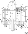
- Figure 1 shows a sectional view of an actuating device 1 for a hydraulic brake system of a motor vehicle.
- the actuating device 1 has a master brake cylinder 2.
- the master brake cylinder 2 at least one hydraulic piston (not shown) is mounted axially displaceably along a displacement axis 3.
- the master brake cylinder 2 is a tandem master brake cylinder 2. Accordingly, two hydraulic pistons are mounted axially displaceably one behind the other in the master brake cylinder 2.
- the displacement axis 3 corresponds to the longitudinal center axis 3 of the master brake cylinder 2.
- the master brake cylinder 2 is connected to the hydraulic system by a plurality of hydraulic connections, of which Figure 1 only a single hydraulic connection 4 is shown, connected to slave cylinders of friction brake devices of the brake system in such a way that the friction brake devices can be actuated by a displacement of the hydraulic pistons in an actuating device 5.
- the actuating device 1 also has a housing 6.
- the housing 6 is made up of several parts.
- the housing 6 has a base body 7 and a cover 8.
- the base body 7 and the cover 8 are rigidly connected to one another by fastening means 9.
- the actuating device 1 also has an electric motor 10, which is arranged in the housing 6 in a housing-fixed manner.
- the electric motor 10 is designed to drive a drive shaft 11, which is mounted so as to be rotatable about a rotation axis 12.
- the rotation axis 12 is aligned parallel to the displacement axis 3.
- the drive shaft 11 projects axially beyond the electric motor 10 on both sides.
- the drive shaft 11 has a first end section 13, which is arranged axially on one side of the electric motor 10, and a second end section 14, which is arranged axially on the other side of the electric motor 10.
- a first bearing 15 and a second bearing 16 are provided for the rotatable mounting of the drive shaft 11.
- the first bearing 15 supports the first end section 13 of the drive shaft 11.
- the second bearing 16 supports the second end section 14 of the drive shaft 11.
- the bearings 15 and 16 are designed as rolling element bearings 15 and 16.
- the master brake cylinder 2 has a connection flange 17.
- the connection flange 17 lies axially on an outer side of a wall 18 of the cover 8, which is aligned perpendicular to the axis of rotation 12.
- the master brake cylinder 2 is rigidly connected to the housing 6 or rigidly attached to the housing. In this respect, there is a connection acting between the master brake cylinder 2 on the one hand and the housing 6 on the other hand, through which both axial forces and radial forces can be transmitted. If, for example, the master brake cylinder 2 is subjected to an axial force acting in the actuation direction 5, this axial force is transmitted to the housing 6.
- the rigid connection of the master brake cylinder 2 to the housing 6 is provided in part by the drive shaft 11.
- the first bearing 15 and the second bearing 16 are designed to transmit both axial forces and radial forces.
- the first bearing 15 has a first bearing ring 19 and a second bearing ring 20, wherein the bearing rings 19 and 20 can be rotated relative to one another.
- the first bearing ring 19 is rigidly connected to the master brake cylinder 2. In the present case, the first bearing ring 19 is pressed into a first axial opening 21 in the connection flange 17.
- the second bearing ring 20 is rigidly connected to the drive shaft 11. In the present case, the drive shaft 11 is pressed into the second bearing ring 20.
- the second bearing 16 has a third bearing ring 22 and a fourth bearing ring 23, wherein the bearing rings 22 and 23 can be rotated relative to one another.
- the third bearing ring 22 is rigidly connected to the housing 6. In this case, the third bearing ring 22 is pressed into a cup-shaped recess 24 in the base body 7 of the housing 6.
- the fourth bearing ring 23 is rigidly connected to the drive shaft 11. In this case, the drive shaft 11 is pressed into the fourth bearing ring 23. If the master brake cylinder 2 is subjected to an axial force acting in the actuating device 5, this axial force is transmitted to the housing 6 through the first bearing ring 19, the second bearing ring 20, the drive shaft 11, the fourth bearing ring 23 and the third bearing ring 22.
- the actuating device 1 also has a pull rod 25.
- the pull rod 25 is arranged such that a longitudinal center axis 26 of the Pull rod 25 is aligned parallel to the rotation axis 12.
- the rigid connection of the master brake cylinder 2 to the housing 6 is also provided in part by the pull rod 25.
- the pull rod 25 extends axially through the housing 6 and the connecting flange 17 and is axially fixed to the housing 6 and the connecting flange 17 by axial stops 27.
- the actuating device 1 also has an actuating element 28 that is guided in an axially displaceable manner.
- the actuating element 28 is coupled to the hydraulic pistons in such a way that the hydraulic pistons can be displaced by a displacement of the actuating element 28.
- An anti-rotation plate 29 is rigidly connected to the actuating element 28 and can therefore be displaced with the actuating element 28.
- the actuating device 1 has a return spring 30 that is supported axially on the master brake cylinder 2 on the one hand and on the actuating element 28 or an element rigidly connected to the actuating element 28 on the other hand.
- the drive shaft 11 is operatively connected to the actuating element 28 in such a way that the actuating element 28 can be moved by rotating the drive shaft 11.
- the hydraulic pistons can be moved by the electric motor 10.
- the actuating device 1 has a gear device 31.
- the gear device 31 has a first gear 32 which is connected in a rotationally fixed manner to the drive shaft 11.
- the first gear 32 is arranged axially between the electric motor 10 on the one hand and the second bearing 16 on the other.
- the first gear 32 is designed to drive a spindle nut 34 of the gear device 31 by means of at least one further gear 33 of the gear device 31.
- An external thread of the actuating element 28 meshes with an internal thread of the spindle nut 34 in such a way that the actuating element 28 can be moved by rotating the spindle nut 34.
- the guidance of the actuating element 28 is provided in part by the electric motor 10.
- an element of the electric motor 10 that is fixed to the housing for example a carrier of the electric motor 10
- the anti-rotation plate 29 has a recess 36 that extends axially through the anti-rotation plate 29.
- the guide projection 35 engages radially in the recess 36 to guide the actuating element 28.
- the guide projection 35 has a Figure 1 coating (not shown) which reduces friction between the guide projection 35 and the anti-rotation plate 29.
- the anti-rotation plate 29 has a guide projection which engages radially in a recess of the electric motor 10 extending in the axial direction in order to guide the actuating element 28.
- the guidance of the actuating element 28 is also provided in part by the pull rod 25.
- the anti-rotation plate 29 has an axial opening 37 through which the pull rod 25 extends axially to guide the actuating element 28.
- the actuating device 1 also has a control unit 38 for controlling the electric motor 10.
- the control unit 38 is designed to control the electric motor 10 depending on a sensor signal from an actuating sensor (not shown) of the actuating device 1.
- the connection flange 17 is arranged axially between the electric motor 10 on the one hand and the control unit 38 on the other.
- the control unit 38 lies axially directly on the connection flange 17.
- connection flange 17 has a second axial opening 39 which is axially aligned with an axial opening 41 of the cover 8.
- the control unit 38 is electrically connected to a motor winding of the electric motor 10 by several electrical lines 40.
- the electrical lines 40 extend through the second axial opening 39 of the connection flange 17 and through the axial opening 41 of the cover 8.
- a magnetic element 42 is provided which is connected in a rotationally fixed manner to a free end of the first end section 13 of the drive shaft 11.
- a receiver (not shown) is provided which is designed to detect a magnetic field generated by the magnetic element 42.
- the receiver is located radially or axially opposite the magnetic element 42, for example.
- a locking ring 43 is provided.
- the locking ring 43 engages radially in a circumferential groove of the drive shaft 11.
- the locking ring 43 is arranged axially between the magnetic element 42 on the one hand and the first bearing 15 on the other hand and lies axially directly on the second bearing ring 20.
- the drive shaft 11 projects axially beyond the second bearing 16.
- a further locking ring is provided, which is arranged on a side of the second bearing 16 facing away from the first bearing 15 and lies axially directly on the fourth bearing ring 23.
- the further locking ring engages radially in a further circumferential groove of the drive shaft 11.
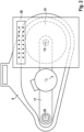
- Figure 2 shows a top view of the actuating device 1.
- the master brake cylinder 2 the pull rod 25 and the drive shaft 11 are arranged such that the longitudinal center axis 26 of the pull rod 25, the longitudinal center axis 3 of the master brake cylinder 2 and the axis of rotation 12 of the drive shaft 11 lie in the same plane.
- the master brake cylinder 2 is arranged radially between the pull rod 25 and the drive shaft 11.
- the longitudinal center axis 26 of the pull rod 25 and the axis of rotation 12 of the drive shaft 11 are equidistant in the radial direction from the longitudinal center axis 3 of the master brake cylinder 2.
- the drive shaft 11 partially provides the rigid connection of the master brake cylinder 2 to the housing 6, and because the electric motor 10 partially provides the guide of the actuating element 28, a further pull rod can be dispensed with, which would typically provide the rigid connection and the guide together with the pull rod 25.
- the actuating device 1 is designed to save space overall, as can be seen from Figure 2 is evident.
Landscapes
- Engineering & Computer Science (AREA)
- Transportation (AREA)
- Mechanical Engineering (AREA)
- Braking Systems And Boosters (AREA)
- Mounting Of Bearings Or Others (AREA)
- Rolling Contact Bearings (AREA)
- Braking Arrangements (AREA)
Description
- Die Erfindung betrifft eine Betätigungseinrichtung für eine Bremsanlage, mit einem Elektromotor, der dazu ausgebildet ist, eine um eine Rotationsachse drehbar gelagerte Antriebswelle anzutreiben, mit einem Gehäuse, und mit einem Hauptbremszylinder, der mit dem Gehäuse starr verbunden ist, wobei in dem Hauptbremszylinder zumindest ein Hydraulikkolben verschiebbar gelagert ist, und wobei die Antriebswelle derart mit dem Hydraulikkolben gekoppelt ist, dass der Hydraulikkolben durch eine Drehung der Antriebswelle verschiebbar ist.
- Außerdem betrifft die Erfindung eine Bremsanlage mit einer derartigen Betätigungseinrichtung.
- Eine hydraulische Bremsanlage eines Kraftfahrzeugs weist in der Regel mehrere Reibbremseinrichtungen auf. Zur Betätigung der Reibbremseinrichtungen ist üblicherweise eine Betätigungseinrichtung mit einem Hauptbremszylinder vorgesehen, in dem zumindest ein Hydraulikkolben verschiebbar gelagert ist. Der Hauptbremszylinder ist dabei mit Nehmerzylindern der Reibbremseinrichtungen derart fluidtechnisch verbunden, dass die Reibbremseinrichtungen durch eine Verschiebung des Hydraulikkolbens betätigbar sind.
- Immer häufiger werden im Kraftfahrzeugbau elektromechanische Betätigungseinrichtungen verbaut. Eine derartige Betätigungseinrichtung ist beispielsweise aus der
Offenlegungsschrift WO 2017 108 228 A1 bekannt. Die Betätigungseinrichtung weist einen Elektromotor auf, der dazu ausgebildet, eine um eine Rotationsachse drehbar gelagerte Antriebswelle anzutreiben. Die Antriebswelle ist derart mit dem Hydraulikkolben gekoppelt, dass der Hydraulikkolben durch eine Drehung der Antriebswelle verschiebbar ist. Der Hydraulikkolben ist also mittels der Antriebswelle durch den Elektromotor verschiebbar, sodass letztlich die Reibbremseinrichtungen durch den Elektromotor betätigbar sind. Die Betätigungseinrichtung weist zudem ein Gehäuse auf, wobei der Hauptbremszylinder mit dem Gehäuse starr verbunden ist. Typischerweise ist in vorbekannten elektromechanischen Betätigungseinrichtungen der Elektromotor außerhalb des Gehäuses angeordnet, mit dem der Hauptbremszylinder starr verbunden ist. - Die Offenlegung
DE 10 2016 113802 A1 befasst sich mit einem Kraftunterstützungssystem das einen Motor mit einer Rotorwelle, eine Antriebsriemenscheibe, die an der Rotorwelle angebracht ist, eine angetriebene Riemenscheibe, einen flexiblen Riemen, der ausgestaltet ist, um die Antriebsriemenscheibe mit der angetriebenen Riemenscheibe zu verbinden, und eine Kugelrollspindelanordnung enthält. Die Kugelrollspindelanordnung enthält eine drehbare Kugelrollspindel, die zusammen mit der angetriebenen Riemenscheibe drehbar ist, eine Spindelmutter mit linearer Übersetzung, die die Kugelrollspindel umgibt, und eine Antirotationsvorrichtung, die angeordnet ist, um eine Drehung der Spindelmutter zu verhindern. - Die erfindungsgemäße Betätigungseinrichtung mit den Merkmalen des Anspruchs 1 hat den Vorteil, dass die Betätigungseinrichtung besonders kompakt und somit bauraumsparend ausgebildet ist. Erfindungsgemäß ist hierzu vorgesehen, dass der Elektromotor in dem Gehäuse angeordnet ist, und dass die starre Verbindung des Hauptbremszylinders mit dem Gehäuse zumindest anteilig durch die Antriebswelle bereitgestellt wird. Der Elektromotor ist also erfindungsgemäß in dem Gehäuse angeordnet, mit dem der Hauptbremszylinder starr verbunden ist. Aufgrund der Anordnung in dem Gehäuse ist der Elektromotor durch das Gehäuse geschützt, sodass auf ein zusätzliches Motorgehäuse verzichtet werden kann. Vorzugsweise ist der Elektromotor motorgehäusefrei ausgebildet. Hierdurch werden zusätzlich zu der Einsparung von Bauraum für die Betätigungseinrichtung auch Kosten eingespart.
- Der Hauptbremszylinder ist erfindungsgemäß mit dem Gehäuse starr verbunden beziehungsweise an dem Gehäuse starr befestigt. Unter einer starren Verbindung zwischen zwei Körpern ist dabei eine Verbindung zu verstehen, die keine Relativbewegung der Körper zueinander zulässt. Insofern ist die starre Verbindung des Hauptbremszylinders mit dem Gehäuse beispielsweise dazu ausgebildet, sowohl Axialkräfte als auch Radialkräfte zu übertragen. Werden in der Offenbarung die Begriffe "axial" und "radial" verwendet, so beziehen sich diese Begriffe auf die Rotationsachse der Antriebswelle, es sei denn, dass ausdrücklich ein anderer Bezug für die Begriffe offenbart ist. Unter einer Axialkraft ist also eine Kraft zu verstehen, die parallel zu der Rotationsachse ausgerichtet ist. Unter einer Radialkraft ist entsprechend eine Kraft zu verstehen, die senkrecht zu der Rotationsachse ausgerichtet ist. Vorzugsweise ist der Hydraulikkolben entlang einer Verschiebeachse verschiebbar, die parallel zu der Rotationsachse der Antriebswelle ausgerichtet ist. Erfindungsgemäß wird die starre Verbindung des Gehäuses mit dem Hauptbremszylinder zumindest anteilig durch die Antriebswelle bereitgestellt beziehungsweise bewirkt. Wird beispielsweise der Hauptbremszylinder mit einer Axialkraft beaufschlagt, so wird diese Axialkraft zumindest anteilig mittels der Antriebswelle auf das Gehäuse übertragen. Weil die starre Verbindung des Gehäuses mit dem Hauptbremszylinder zumindest anteilig durch die Antriebswelle bereitgestellt wird, können sonstige Elemente eingespart werden, durch die üblicherweise in vorbekannten Betätigungseinrichtungen die starre Verbindung anteilig bereitgestellt wird. Auch daraus ergibt sich die bauraumsparende Ausbildung der erfindungsgemäßen Betätigungseinrichtung.
- Vorzugsweise weist die Betätigungseinrichtung ein zur Übertragung von Axialkräften ausgebildetes erstes Lager auf, das einen ersten Lagerring und einen zweiten Lagerring aufweist, wobei der erste Lagerring mit dem Hauptbremszylinder starr verbunden ist, und wobei der zweite Lagerring mit der Antriebswelle starr verbunden ist. Die starre Verbindung des Gehäuses mit dem Hauptbremszylinder wird also zumindest anteilig durch das erste Lager bereitgestellt. Wird der Hauptbremszylinder mit einer Axialkraft beaufschlagt, so wird diese Axialkraft mittels des ersten Lagerrings und des zweiten Lagerrings auf die Antriebswelle übertragen. Mittels des ersten Lagers können trotz drehbarer Lagerung der Antriebswelle ausreichend hohe Axialkräfte auf die Antriebswelle übertragen werden. Vorzugsweise handelt es sich bei dem ersten Lagerring um einen äußeren Lagerring des ersten Lagers. Entsprechend handelt es sich dann bei dem zweiten Lagerring um einen inneren Lagerring des ersten Lagers. Vorzugsweise ist der zweite Lagerring durch eine Presspassung mit der Antriebswelle verbunden. Vorzugsweise ist der zweite Lagerring mit einem ersten Endabschnitt der Antriebswelle verbunden. Besonders bevorzugt ist das erste Lager außerhalb des Gehäuses angeordnet. Entsprechend weist die Antriebswelle einen Abschnitt auf, der aus dem Gehäuse herausragt.
- Vorzugsweise weist die Betätigungseinrichtung ein zur Übertragung von Axialkräften ausgebildetes zweites Lager auf, das einen dritten Lagerring und einen vierten Lagerring aufweist, wobei der dritte Lagerring gehäusefest angeordnet ist, und wobei der vierte Lagerring mit der Antriebswelle starr verbunden ist. Die starre Verbindung des Gehäuses mit dem Hauptbremszylinder wird also zumindest anteilig durch das zweite Lager bereitgestellt. Wird die Antriebswelle mit einer Axialkraft beaufschlagt, so wird diese Axialkraft mittels des vierten Lagerrings und des dritten Lagerrings auf das Gehäuse übertragen. Mittels des zweiten Lagers können trotz drehbarer Lagerung der Antriebswelle ausreichend hohe Axialkräfte von der Antriebswelle auf das Gehäuse übertragen werden. Vorzugsweise handelt es sich bei dem dritten Lagerring um einen äußeren Lagerring des zweiten Lagers. Entsprechend handelt es sich dann bei dem vierten Lagerring um einen inneren Lagerring des zweiten Lagers. Vorzugsweise ist der vierte Lagerring durch eine Presspassung mit der Antriebswelle verbunden. Vorzugsweise ist der vierte Lagerring mit einem zweiten Endabschnitt der Antriebswelle verbunden. Ist das erste Lager im Bereich des ersten Endabschnitts der Antriebswelle mit der Antriebswelle verbunden und das zweite Lager im Bereich des zweiten Endabschnitts der Antriebswelle, so ist der Elektromotor axial zwischen dem ersten Lager einerseits und dem zweiten Lager andererseits angeordnet. Hierdurch wird eine stabile drehbare Lagerung der Antriebswelle mittels der beiden Lager erreicht.
- Gemäß einer bevorzugten Ausführungsform ist vorgesehen, dass das erste Lager und/oder das zweite Lager als Wälzkörperlager, insbesondere Kegelrollenlager, ausgebildet sind. Durch derartige Lager wird zum einen eine reibungsarme Drehung der Antriebswelle ermöglicht. Zum anderen können durch derartige Lager ausreichend hohe Axialkräfte übertragen werden. Im Hinblick auf die Übertragung hoher Axialkräfte ist die Ausbildung der Lager als Kegelrollenlager besonders vorteilhaft.
- Vorzugsweise weist das Gehäuse eine becherförmige Vertiefung auf, wobei das zweite Lager in der Vertiefung angeordnet ist. Durch das Vorsehen der Vertiefung und die Anordnung des zweiten Lagers in der Vertiefung kann eine besonders stabile Verbindung des dritten Lagerrings mit dem Gehäuse erreicht werden. Vorzugsweise ist der dritte Lagerring in die Vertiefung eingepresst. Der dritte Lagerring ist also durch eine Presspassung mit dem Gehäuse verbunden, die zwischen einer Mantelwand der Vertiefung und einer Mantelwand des dritten Lagerrings wirkt.
- Vorzugsweise weist der Hauptbremszylinder einen Anschlussflansch auf, wobei der erste Lagerring mit dem Anschlussflansch starr verbunden ist. Durch den Anschlussflansch kann eine stabile Verbindung des Hauptbremszylinders mit dem Gehäuse bereitgestellt werden. Vorzugsweise weist der Anschlussflansch einen Axialdurchbruch auf, in dem das erste Lager angeordnet ist. Vorzugsweise ist der erste Lagerring durch eine Presspassung mit dem Anschlussflansch verbunden, die zwischen einer Mantelwand des Axialdurchbruchs und einer Mantelwand des ersten Lagerrings wirkt.
- Vorzugsweise weist die Betätigungseinrichtung ein Steuergerät zur Ansteuerung des Elektromotors auf, wobei der Anschlussflansch axial zwischen dem Elektromotor einerseits und dem Steuergerät andererseits angeordnet ist. Diese Anordnung des Steuergerätes ist besonders vorteilhaft. Zum einen befindet sich das Steuergerät bei einer derartigen Anordnung in räumlicher Nähe zu dem Elektromotor, wodurch eine elektrische Anbindung des Steuergerätes an den Elektromotor technisch einfach möglich ist. Zum anderen wird das Steuergerät durch die räumliche Nähe zu dem Anschlussflansch im Betrieb durch den Anschlussflansch entwärmt beziehungsweise gekühlt. Vorzugsweise liegt das Steuergerät, insbesondere ein Steuergerätgehäuse des Steuergerätes, axial direkt an dem Anschlussflansch an.
- Gemäß einer bevorzugten Ausführungsform ist vorgesehen, dass das Steuergerät durch zumindest eine elektrische Leitung mit einer Motorwicklung des Elektromotors elektrisch verbunden ist, wobei der Anschlussflansch einen Axialdurchbruch aufweist, durch den sich die Leitung hindurch erstreckt. Die Leitung verläuft also durch den Anschlussflansch hindurch. Dadurch ist die Leitung durch den Anschlussflansch geschützt und die elektrische Verbindung des Steuergerätes mit der Motorwicklung wird insofern vereinfacht, als dass die Leitung nicht um den Anschlussflansch herum geführt werden muss.
- Vorzugsweise weist die Betätigungseinrichtung zumindest einen Sicherungsring auf, der zur axialen Sicherung der Antriebswelle radial in eine Umfangsnut der Antriebswelle eingreift. Hierdurch wird die Höhe der Axialkräfte, die durch die Antriebswelle übertragen werden können, gesteigert. Vorzugsweise liegt der Sicherungsring axial direkt an dem zweiten Lagerring des ersten Lagers oder dem vierten Lagerring des zweiten Lagers an. Besonders bevorzugt ist der Sicherungsring auf einer von dem zweiten Lager abgewandten Seite des ersten Lagers angeordnet und liegt axial direkt an dem zweiten Lagerring des ersten Lagers an. Vorzugsweise weist die Betätigungseinrichtung dann einen weiteren Sicherungsring auf, der zur axialen Sicherung der Antriebswelle radial in eine weitere Umfangsnut der Antriebswelle eingreift, auf einer von dem ersten Lager abgewandten Seite des zweiten Lagers angeordnet ist und axial direkt an dem vierten Lagerring des zweiten Lagers anliegt.
- Vorzugsweise weist die Betätigungseinrichtung ein Betätigungselement auf, das in dem Gehäuse verschiebbar geführt ist, wobei die Führung des Betätigungselementes zumindest anteilig durch den Elektromotor bereitgestellt wird. Unter dem Betätigungselement ist ein Element zu verstehen, das derart mit dem Hydraulikkolben gekoppelt ist, dass der Hydraulikkolben durch eine Verschiebung des Betätigungselementes verschiebbar ist. Vorzugsweise ist die Antriebswelle mittels des Betätigungselementes mit dem Hydraulikkolben gekoppelt. Weil die Führung des Betätigungselementes zumindest anteilig durch den Elektromotor bereitgestellt wird, ist höchstens eine geringe Anzahl sonstiger Bauteile für die Führung des Betätigungselementes notwendig.
- Vorzugsweise weist die Betätigungseinrichtung eine mit dem Betätigungselement starr verbundene Drehsicherungsplatte auf, wobei ein gehäusefestes Element des Elektromotors einen Führungsvorsprung aufweist, der zur Führung des Betätigungselementes radial in eine Aussparung der Drehsicherungsplatte eingreift. Hierdurch wird eine sichere Führung des Betätigungselementes erreicht. Vorzugsweise weist der Führungsvorsprung eine Beschichtung auf, durch die eine Reibung zwischen dem Führungsvorsprung und der Drehsicherungsplatte verringert wird. Gemäß einem weiteren Ausführungsbeispiel weist die Drehsicherungsplatte einen Führungsvorsprung auf, der zur Führung des Betätigungselementes radial in eine Aussparung des gehäusefesten Elementes des Elektromotors eingreift.
- Vorzugsweise weist die Betätigungseinrichtung eine Zugstange auf, wobei die starre Verbindung des Gehäuses mit dem Hauptbremszylinder sowie die Führung des Betätigungselementes jeweils anteilig durch die Zugstange bereitgestellt werden. Durch das Vorsehen der Zugstange werden die Stabilität der starren Verbindung des Gehäuses mit dem Hauptbremszylinder sowie die Stabilität der Führung des Betätigungselementes gesteigert. Vorzugsweise weist die Betätigungseinrichtung genau eine wie vorstehend beschrieben ausgebildete Zugstange auf.
- Gemäß einer bevorzugten Ausführungsform ist vorgesehen, dass eine Längsmittelachse des Hauptbremszylinders, eine Längsmittelachse der Zugstange und die Rotationsachse der Antriebswelle parallel zueinander ausgerichtet sind und in derselben Ebene liegen, wobei der Hauptbremszylinder radial zwischen der Zugstange einerseits und der Antriebswelle andererseits angeordnet ist. Durch eine derartige Ausgestaltung werden Axialkräfte, die auf den Hauptbremszylinder wirken, vorteilhaft auf die Zugstange und die Antriebswelle aufgeteilt.
- Die erfindungsgemäße Bremsanlage zeichnet sich mit den Merkmalen des Anspruchs 14 durch die erfindungsgemäße Betätigungseinrichtung aus. Auch daraus ergeben sich die bereits genannten Vorteile. Weitere bevorzugte Merkmale und Merkmalskombinationen ergeben sich aus der Beschreibung sowie aus den Ansprüchen. Vorzugsweise weist die Bremsanlage zumindest eine Reibbremseinrichtung auf, die fluidtechnisch derart mit dem Hauptbremszylinder verbunden ist, dass die Reibbremseinrichtung durch eine Verschiebung des Hydraulikkolbens betätigbar ist.
- Im Folgenden wird die Erfindung anhand der Zeichnungen näher erläutert. Dazu zeigen
- Figur 1
- eine Schnittdarstellung einer Betätigungseinrichtung für eine Bremsanlage und
- Figur 2
- eine Draufsicht auf die Betätigungseinrichtung.
-
Figur 1 zeigt eine Schnittdarstellung einer Betätigungseinrichtung 1 für eine hydraulische Bremsanlage eines Kraftfahrzeugs. Die Betätigungseinrichtung 1 weist einen Hauptbremszylinder 2 auf. In dem Hauptbremszylinder 2 ist zumindest ein nicht dargestellter Hydraulikkolben entlang einer Verschiebeachse 3 axial verschiebbar gelagert. Vorliegend handelt es sich bei dem Hauptbremszylinder 2 um einen Tandem-Hauptbremszylinder 2. Entsprechend sind in dem Hauptbremszylinder 2 zwei Hydraulikkolben axial hintereinander verschiebbar gelagert. Die Verschiebeachse 3 entspricht dabei der Längsmittelachse 3 des Hauptbremszylinders 2. Ist die Betätigungseinrichtung 1 als Teil der Bremsanlage in dem Kraftfahrzeug montiert, so ist der Hauptbremszylinder 2 durch mehrere Hydraulikanschlüsse, von denen inFigur 1 lediglich ein einziger Hydraulikanschluss 4 dargestellt ist, derart mit Nehmerzylindern von Reibbremseinrichtungen der Bremsanlage verbunden, dass die Reibbremseinrichtungen durch eine Verschiebung der Hydraulikkolben in eine Betätigungseinrichtung 5 betätigbar sind. - Die Betätigungseinrichtung 1 weist außerdem ein Gehäuse 6 auf. Das Gehäuse 6 ist mehrteilig ausgebildet. Vorliegend weist das Gehäuse 6 einen Grundkörper 7 und eine Abdeckung 8 auf. Der Grundkörper 7 und die Abdeckung 8 sind durch Befestigungsmittel 9 miteinander starr verbunden.
- Die Betätigungseinrichtung 1 weist außerdem einen Elektromotor 10 auf, der gehäusefest in dem Gehäuse 6 angeordnet ist. Der Elektromotor 10 ist dazu ausgebildet, eine Antriebswelle 11 anzutreiben, die um eine Rotationsachse 12 drehbar gelagert ist. Dabei ist die Rotationsachse 12 parallel zu der Verschiebeachse 3 ausgerichtet. Die Antriebswelle 11 ragt axial beidseitig über den Elektromotor 10 hinaus. Insofern weist die Antriebswelle 11 einen ersten Endabschnitt 13 auf, der axial auf der einen Seite des Elektromotors 10 angeordnet ist, und einen zweiten Endabschnitt 14, der axial auf der anderen Seite des Elektromotors 10 angeordnet ist. Zur drehbaren Lagerung der Antriebswelle 11 sind ein erstes Lager 15 und ein zweites Lager 16 vorgesehen. Dabei lagert das erste Lager 15 den ersten Endabschnitt 13 der Antriebswelle 11. Das zweite Lager 16 lagert den zweiten Endabschnitt 14 der Antriebswelle 11. Vorliegend sind die Lager 15 und 16 als Wälzkörperlager 15 und 16 ausgebildet.
- Der Hauptbremszylinder 2 weist einen Anschlussflansch 17 auf. Der Anschlussflansch 17 liegt axial an einer Außenseite einer Wand 18 der Abdeckung 8 an, die senkrecht zu der Rotationsachse 12 ausgerichtet ist. Der Hauptbremszylinder 2 ist mit dem Gehäuse 6 starr verbunden beziehungsweise an dem Gehäuse starr befestigt. Insofern ist eine zwischen dem Hauptbremszylinder 2 einerseits und dem Gehäuse 6 andererseits wirkende Verbindung vorhanden, durch die sowohl Axialkräfte als auch Radialkräfte übertragbar sind. Wird beispielsweise der Hauptbremszylinder 2 mit einer in Betätigungsrichtung 5 wirkenden Axialkraft beaufschlagt, so wird diese Axialkraft auf das Gehäuse 6 übertragen.
- Dabei wird die starre Verbindung des Hauptbremszylinders 2 mit dem Gehäuse 6 anteilig durch die Antriebswelle 11 bereitgestellt. Das erste Lager 15 und das zweite Lager 16 sind dazu ausgebildet, sowohl Axialkräfte als auch Radialkräfte zu übertragen. Das erste Lager 15 weist hierzu einen ersten Lagerring 19 und einen zweiten Lagerring 20 auf, wobei die Lagerringe 19 und 20 zueinander verdrehbar sind. Der erste Lagerring 19 ist mit dem Hauptbremszylinder 2 starr verbunden. Vorliegend ist der erste Lagerring 19 in einen ersten Axialdurchbruch 21 des Anschlussflansches 17 eingepresst. Der zweite Lagerring 20 ist mit der Antriebswelle 11 starr verbunden. Vorliegend ist die Antriebswelle 11 in den zweiten Lagerring 20 eingepresst. Das zweite Lager 16 weist einen dritten Lagerring 22 und einen vierten Lagerring 23 auf, wobei die Lagerringe 22 und 23 zueinander verdrehbar sind. Der dritte Lagerring 22 ist mit dem Gehäuse 6 starr verbunden. Vorliegend ist der dritte Lagerring 22 in eine becherförmige Vertiefung 24 des Grundkörpers 7 des Gehäuses 6 eingepresst. Der vierte Lagerring 23 ist mit der Antriebswelle 11 starr verbunden. Vorliegend ist die Antriebswelle 11 in den vierten Lagerring 23 eingepresst. Wird also der Hauptbremszylinder 2 mit einer in Betätigungseinrichtung 5 wirkenden Axialkraft beaufschlagt, so wird diese Axialkraft durch den ersten Lagerring 19, den zweiten Lagerring 20, die Antriebswelle 11, den vierten Lagerring 23 und den dritten Lagerring 22 auf das Gehäuse 6 übertragen.
- Die Betätigungseinrichtung 1 weist außerdem eine Zugstange 25 auf. Die Zugstange 25 ist derart angeordnet, dass eine Längsmittelachse 26 der Zugstange 25 parallel zu der Rotationsachse 12 ausgerichtet ist. Die starre Verbindung des Hauptbremszylinders 2 mit dem Gehäuse 6 wird auch anteilig durch die Zugstange 25 bereitgestellt. Hierzu erstreckt sich die Zugstange 25 axial durch das Gehäuse 6 und den Anschlussflansch 17 hindurch und ist durch Axialanschläge 27 axial an dem Gehäuse 6 und dem Anschlussflansch 17 fixiert.
- Die Betätigungseinrichtung 1 weist außerdem ein axial verschiebbar geführtes Betätigungselement 28 auf. Das Betätigungselement 28 ist derart mit den Hydraulikkolben gekoppelt, dass die Hydraulikkolben durch eine Verschiebung des Betätigungselementes 28 verschiebbar sind. Eine Drehsicherungsplatte 29 ist mit dem Betätigungselement 28 starr verbunden und insofern mit dem Betätigungselement 28 mitverschiebbar. Zudem weist die Betätigungseinrichtung 1 eine Rückstellfeder 30 auf, die sich axial an dem Hauptbremszylinder 2 einerseits und an dem Betätigungselement 28 oder einem mit dem Betätigungselement 28 starr verbundenen Element andererseits abstützt.
- Die Antriebswelle 11 ist derart mit dem Betätigungselement 28 wirkverbunden, dass das Betätigungselement 28 durch eine Drehung der Antriebswelle 11 verschiebbar ist. Insofern sind die Hydraulikkolben durch den Elektromotor 10 verschiebbar. Hierzu weist die Betätigungseinrichtung 1 eine Getriebeeinrichtung 31 auf. Die Getriebeeinrichtung 31 weist ein erstes Zahnrad 32 auf, das drehfest mit der Antriebswelle 11 verbunden ist. Das erste Zahnrad 32 ist axial zwischen dem Elektromotor 10 einerseits und dem zweiten Lager 16 andererseits angeordnet. Das erste Zahnrad 32 ist dazu ausgebildet, mittels zumindest eines weiteren Zahnrads 33 der Getriebereinrichtung 31 eine Spindelmutter 34 der Getriebeeinrichtung 31 anzutreiben. Ein Außengewinde des Betätigungselementes 28 kämmt derart mit einem Innengewinde der Spindelmutter 34, dass das Betätigungselement 28 durch eine Drehung der Spindelmutter 34 verschiebbar ist.
- Die Führung des Betätigungselementes 28 wird anteilig durch den Elektromotor 10 bereitgestellt. Vorliegend weist ein gehäusefestes Element des Elektromotors 10, beispielsweise ein Träger des Elektromotors 10, einen Führungsvorsprung 35 auf, der sich in axialer Richtung erstreckt. Die Drehsicherungsplatte 29 weist eine Aussparung 36 auf, die sich axial durch die Drehsicherungsplatte 29 hindurch erstreckt. Der Führungsvorsprung 35 greift zur Führung des Betätigungselementes 28 radial in die Aussparung 36 ein. Der Führungsvorsprung 35 weist eine in
Figur 1 nicht dargestellte Beschichtung auf, durch die eine Reibung zwischen dem Führungsvorsprung 35 und der Drehsicherungsplatte 29 verringert wird. Gemäß einem weiteren Ausführungsbeispiel weist die Drehsicherungsplatte 29 einen Führungsvorsprung auf, der zur Führung des Betätigungselementes 28 radial in eine sich in axialer Richtung erstreckende Aussparung des Elektromotors 10 eingreift. - Die Führung des Betätigungselementes 28 wird zudem anteilig durch die Zugstange 25 bereitgestellt. Hierzu weist die Drehsicherungsplatte 29 einen Axialdurchbruch 37 auf, durch den die Zugstange 25 zur Führung des Betätigungselementes 28 axial hindurchgreift.
- Die Betätigungseinrichtung 1 weist außerdem ein Steuergerät 38 zur Ansteuerung des Elektromotors 10 auf. Beispielsweise ist das Steuergerät 38 dazu ausgebildet, den Elektromotor 10 in Abhängigkeit von einem Sensorsignal eines nicht dargestellten Betätigungssensors der Betätigungseinrichtung 1 anzusteuern. Der Anschlussflansch 17 ist axial zwischen dem Elektromotor 10 einerseits und dem Steuergerät 38 andererseits angeordnet. Dabei liegt das Steuergerät 38 axial direkt an dem Anschlussflansch 17 an.
- Der Anschlussflansch 17 weist einen zweiten Axialdurchbruch 39 auf, der axial mit einem Axialdurchbruch 41 der Abdeckung 8 fluchtet. Das Steuergerät 38 ist durch mehrere elektrische Leitungen 40 elektrisch mit einer Motorwicklung des Elektromotors 10 verbunden. Die elektrischen Leitungen 40 erstrecken sich durch den zweiten Axialdurchbruch 39 des Anschlussflansches 17 und durch den Axialdurchbruch 41 der Abdeckung 8 hindurch.
- Um einen Drehwinkel der Antriebswelle 11 zu überwachen, ist ein Magnetelement 42 vorgesehen, das mit einem freien Ende des ersten Endabschnitts 13 der Antriebswelle 11 drehfest verbunden ist. Zudem ist ein nicht dargestellter Empfänger vorgesehen, der dazu ausgebildet ist, ein durch das Magnetelement 42 erzeugtes Magnetfeld zu erfassen. Hierzu liegt der Empfänger dem Magnetelement 42 beispielsweise radial oder axial gegenüber.
- Um die Antriebswelle 11 axial zu sichern ist ein Sicherungsring 43 vorgesehen. Der Sicherungsring 43 greift radial in eine Umfangsnut der Antriebswelle 11 ein. Dabei ist der Sicherungsring 43 axial zwischen dem Magnetelement 42 einerseits und dem ersten Lager 15 andererseits angeordnet und liegt axial direkt an dem zweiten Lagerring 20 an. Gemäß einem weiteren Ausführungsbeispiel ragt die Antriebswelle 11 axial über das zweite Lager 16 hinaus. Vorzugsweise ist gemäß diesem Ausführungsbeispiel ein weiterer Sicherungsring vorgesehen, der auf einer von dem ersten Lager 15 abgewandten Seite des zweiten Lagers 16 angeordnet ist und axial direkt an dem vierten Lagerring 23 anliegt. Vorzugsweise greift der weitere Sicherungsring radial in eine weitere Umfangsnut der Antriebswelle 11 ein.
-
Figur 2 zeigt eine Draufsicht auf die Betätigungseinrichtung 1. Wie ausFigur 2 ersichtlich ist, sind der Hauptbremszylinder 2, die Zugstange 25 und die Antriebswelle 11 derart angeordnet, dass die Längsmittelachse 26 der Zugstange 25, die Längsmittelachse 3 des Hauptbremszylinder 2 und die Rotationsachse 12 der Antriebswelle 11 in derselben Ebene liegen. Dabei ist der Hauptbremszylinder 2 radial zwischen der Zugstange 25 und der Antriebswelle 11 angeordnet. Zudem sind die Längsmittelachse 26 der Zugstange 25 und die Rotationsachse 12 der Antriebswelle 11 in radialer Richtung gleichweit von der Längsmittelachse 3 des Hauptbremszylinders 2 beabstandet. - Weil die Antriebswelle 11 anteilig die starre Verbindung des Hauptbremszylinders 2 mit dem Gehäuse 6 bereitstellt, und weil der Elektromotor 10 anteilig die Führung des Betätigungselementes 28 bereitstellt, kann auf eine weitere Zugstange verzichtet werden, die typischerweise zusammen mit der Zugstange 25 die starre Verbindung sowie die Führung bereitstellen würde. Hierdurch ist die Betätigungseinrichtung 1 insgesamt bauraumsparend ausgebildet, wie aus
Figur 2 ersichtlich ist.
Claims (14)
- Betätigungseinrichtung (1) für eine Bremsanlage, mit einem Elektromotor (10), der dazu ausgebildet ist, eine um eine Rotationsachse (12) drehbar gelagerte Antriebswelle (11) anzutreiben, mit einem Gehäuse (6), und mit einem Hauptbremszylinder (2), der mit dem Gehäuse (6) starr verbunden ist, wobei in dem Hauptbremszylinder (2) zumindest ein Hydraulikkolben verschiebbar gelagert ist, und wobei die Antriebswelle (11) derart mit dem Hydraulikkolben gekoppelt ist, dass der Hydraulikkolben durch eine Drehung der Antriebswelle (11) verschiebbar ist wobei der Elektromotor (10) in dem Gehäuse (6) angeordnet ist, dadurch gekennzeichnet, dass die starre Verbindung des Hauptbremszylinders (2) mit dem Gehäuse (6) zumindest anteilig durch die Antriebswelle (11) bereitgestellt wird.
- Betätigungseinrichtung nach Anspruch 1, gekennzeichnet durch ein zur Übertragung von Axialkräften ausgebildetes erstes Lager (15), das einen ersten Lagerring (19) und einen zweiten Lagerring (20) aufweist, wobei der erste Lagerring (19) mit dem Hauptbremszylinder (2) starr verbunden ist, und wobei der zweite Lagerring (20) mit der Antriebswelle (11) starr verbunden ist.
- Betätigungseinrichtung nach einem der vorhergehenden Ansprüche, gekennzeichnet durch ein zur Übertragung von Axialkräften ausgebildetes zweites Lager (16), das einen dritten Lagerring (22) und einen vierten Lagerring (23) aufweist, wobei der dritte Lagerring (22) gehäusefest angeordnet ist, und wobei der vierte Lagerring (23) mit der Antriebswelle (11) starr verbunden ist.
- Betätigungseinrichtung nach einem der Ansprüche 2 und 3, dadurch gekennzeichnet, dass das erste Lager (15) und/oder das zweite Lager (16) als Wälzkörperlager, insbesondere Kegelrollenlager, ausgebildet sind.
- Betätigungseinrichtung nach einem der Ansprüche 2 bis 4, dadurch gekennzeichnet, dass das Gehäuse (6) eine becherförmige Vertiefung (24) aufweist, wobei das zweite Lager (16) in der Vertiefung (24) angeordnet ist.
- Betätigungseinrichtung nach einem der Ansprüche 2 bis 5, dadurch gekennzeichnet, dass der Hauptbremszylinder (2) einen Anschlussflansch (17) aufweist, und dass der erste Lagerring (19) mit dem Anschlussflansch (17) starr verbunden ist.
- Betätigungseinrichtung nach einem der vorhergehenden Ansprüche, gekennzeichnet durch ein Steuergerät (38) zur Ansteuerung des Elektromotors (10), wobei der Anschlussflansch (17) axial zwischen dem Elektromotor (10) einerseits und dem Steuergerät (38) andererseits angeordnet ist.
- Betätigungseinrichtung nach Anspruch 7, dadurch gekennzeichnet, dass das Steuergerät (38) durch zumindest eine elektrische Leitung (40) mit einer Motorwicklung des Elektromotors (10) elektrisch verbunden ist, wobei der Anschlussflansch (17) einen Axialdurchbruch (39) aufweist, durch den sich die Leitung (40) hindurch erstreckt.
- Betätigungseinrichtung nach einem der vorhergehenden Ansprüche, gekennzeichnet durch zumindest einen Sicherungsring (43), der zur axialen Sicherung der Antriebswelle (11) radial in eine Umfangsnut der Antriebswelle (11) eingreift.
- Betätigungseinrichtung nach einem der vorhergehenden Ansprüche, gekennzeichnet durch ein Betätigungselement (28), das in dem Gehäuse (6) verschiebbar geführt ist, wobei die Führung des Betätigungselementes (28) zumindest anteilig durch den Elektromotor (10) bereitgestellt wird.
- Betätigungseinrichtung nach Anspruch 10, gekennzeichnet durch eine mit dem Betätigungselement (28) starr verbundene Drehsicherungsplatte (29), wobei ein gehäusefestes Element des Elektromotors (10) einen Führungsvorsprung (35) aufweist, der zur Führung des Betätigungselementes (28) radial in eine Aussparung (36) der Drehsicherungsplatte (29) eingreift.
- Betätigungseinrichtung nach einem der vorhergehenden Ansprüche, dadurch gekennzeichnet, dass die Betätigungseinrichtung (1) eine Zugstange (25) aufweist, wobei die starre Verbindung des Gehäuses (6) mit dem Hauptbremszylinder (2) sowie die Führung des Betätigungselementes (28) jeweils anteilig durch die Zugstange (25) bereitgestellt werden.
- Betätigungseinrichtung nach Anspruch 12, dadurch gekennzeichnet, dass eine Längsmittelachse (3) des Hauptbremszylinders (2), eine Längsmittelachse (26) der Zugstange (25) und die Rotationsachse (12) der Antriebswelle (11) parallel zueinander ausgerichtet sind und in derselben Ebene liegen, wobei der Hauptbremszylinder (2) radial zwischen der Zugstange (25) einerseits und der Antriebswelle (11) andererseits angeordnet ist.
- Bremsanlage, gekennzeichnet durch eine Betätigungseinrichtung (1) gemäß einem der vorhergehenden Ansprüche.
Applications Claiming Priority (2)
| Application Number | Priority Date | Filing Date | Title |
|---|---|---|---|
| DE102021201079.2A DE102021201079A1 (de) | 2021-02-05 | 2021-02-05 | Betätigungseinrichtung für eine Bremsanlage, Bremsanlage |
| PCT/EP2022/051575 WO2022167265A1 (de) | 2021-02-05 | 2022-01-25 | Betätigungseinrichtung für eine bremsanlage |
Publications (2)
| Publication Number | Publication Date |
|---|---|
| EP4288313A1 EP4288313A1 (de) | 2023-12-13 |
| EP4288313B1 true EP4288313B1 (de) | 2024-12-11 |
Family
ID=80168256
Family Applications (1)
| Application Number | Title | Priority Date | Filing Date |
|---|---|---|---|
| EP22702231.6A Active EP4288313B1 (de) | 2021-02-05 | 2022-01-25 | Betätigungseinrichtung für eine bremsanlage |
Country Status (7)
| Country | Link |
|---|---|
| US (1) | US20230391308A1 (de) |
| EP (1) | EP4288313B1 (de) |
| JP (1) | JP7673211B2 (de) |
| KR (1) | KR20230144039A (de) |
| CN (1) | CN116829425A (de) |
| DE (1) | DE102021201079A1 (de) |
| WO (1) | WO2022167265A1 (de) |
Family Cites Families (9)
| Publication number | Priority date | Publication date | Assignee | Title |
|---|---|---|---|---|
| CA2392215A1 (en) * | 1999-11-24 | 2001-05-31 | William Lunceford Barnett | Hydraulic brake system for vehicles |
| CN103144625A (zh) | 2013-03-26 | 2013-06-12 | 清华大学 | 一种使用电磁阀的集成式车辆制动执行装置 |
| JP6238647B2 (ja) | 2013-08-30 | 2017-11-29 | 日立オートモティブシステムズ株式会社 | 電動倍力装置 |
| DE102016113802A1 (de) * | 2015-07-28 | 2017-02-02 | Steering Solutions Ip Holding Corporation | Kraftunterstützungssystem mit Spindelmutter, Bremsverstärkungsaktor und Verfahren |
| DE102015226508A1 (de) | 2015-12-22 | 2017-06-22 | Robert Bosch Gmbh | Elektromechanischer Bremskraftverstärker und Bremssystem |
| JP6838783B2 (ja) | 2017-06-26 | 2021-03-03 | 日立Astemo株式会社 | 電動倍力装置 |
| DE102017216664A1 (de) | 2017-09-20 | 2019-03-21 | Continental Teves Ag & Co. Ohg | Elektrischer Hohlwellenmotor |
| JP7172062B2 (ja) | 2018-03-02 | 2022-11-16 | 日本精工株式会社 | 電動ブレーキシステム |
| DE102019205975A1 (de) * | 2019-04-25 | 2020-10-29 | Robert Bosch Gmbh | Elektromechanisch antreibbarer Bremsdruckerzeuger für ein hydraulisches Bremssystem eines Fahrzeuges sowie Fahrzeug, umfassend einen elektromechanischen Bremsdruckerzeuger |
-
2021
- 2021-02-05 DE DE102021201079.2A patent/DE102021201079A1/de active Pending
-
2022
- 2022-01-25 CN CN202280013582.XA patent/CN116829425A/zh active Pending
- 2022-01-25 KR KR1020237029702A patent/KR20230144039A/ko active Pending
- 2022-01-25 US US18/254,048 patent/US20230391308A1/en active Pending
- 2022-01-25 WO PCT/EP2022/051575 patent/WO2022167265A1/de not_active Ceased
- 2022-01-25 EP EP22702231.6A patent/EP4288313B1/de active Active
- 2022-01-25 JP JP2023544621A patent/JP7673211B2/ja active Active
Also Published As
| Publication number | Publication date |
|---|---|
| EP4288313A1 (de) | 2023-12-13 |
| WO2022167265A1 (de) | 2022-08-11 |
| JP7673211B2 (ja) | 2025-05-08 |
| DE102021201079A1 (de) | 2022-08-11 |
| KR20230144039A (ko) | 2023-10-13 |
| US20230391308A1 (en) | 2023-12-07 |
| JP2024503747A (ja) | 2024-01-26 |
| CN116829425A (zh) | 2023-09-29 |
Similar Documents
| Publication | Publication Date | Title |
|---|---|---|
| DE112011101281B4 (de) | Hydrostataktor | |
| EP1955796B1 (de) | Maschinenspindel mit einer Spannvorrichtung | |
| DE4337867A1 (de) | Differential-Linearaktuator | |
| WO1999045292A1 (de) | Betätigungseinheit für eine elektromechanisch betätigbare scheibenbremse | |
| WO2015117612A2 (de) | Aktor mit planetenwälzgewindespindel (pwg) | |
| EP3584132A1 (de) | Elektromechanischer bremskraftverstärker und bremssystem | |
| EP3350046B1 (de) | Elektromechanischer bremskraftverstärker | |
| EP3837151B1 (de) | Lenkgetriebe für ein steer-by-wire-lenksystem | |
| DE102018211443A1 (de) | Druckerzeugungsvorrichtung für ein Bremssystem eines Fahrzeugs | |
| DE102015204074A1 (de) | Linearer Stellantrieb und Verfahren zur Montage eines Stellantriebs | |
| DE102005055084B4 (de) | Kombinierte Betriebs- und Feststellbremseinrichtung | |
| DE102022210556A1 (de) | Elektromechanischer Linearaktuator | |
| EP3042815B1 (de) | Fahrantrieb eines flurförderzeugs mit einem elektromotor und mit einer federspeicherbremseinrichtung | |
| DE102013107378A1 (de) | Antriebsvorrichtung | |
| EP4288313B1 (de) | Betätigungseinrichtung für eine bremsanlage | |
| EP3759368B1 (de) | Kupplungsanordnung mit zusätzlichem stützlager; sowie antriebseinheit | |
| EP1752586B1 (de) | Übertragungssystem für hydrostatisch angetriebenes Fahrzeug mit drehbarem Oberwagen und mit hydrostatischer Kolbenmaschine mit Stellungsrückmeldung | |
| DE69721164T2 (de) | Elektrische Servolenkung | |
| EP2187097A1 (de) | Linearantrieb | |
| DE102015204071B4 (de) | Linearer Stellantrieb und Verfahren zur Montage eines Stellantriebs | |
| EP3224932B1 (de) | Linearantrieb, aufweisend einen von einem elektromotor über eine kupplung antreibbaren spindeltrieb | |
| DE102017124131A1 (de) | Betätigungsvorrichtung mit zwei Kugelsegmenten mit unterschiedlichem Durchmesser und Schalteinheit | |
| EP1569837A2 (de) | Ventil für eine hydraulische servolenkung | |
| EP0521121A1 (de) | Hilfskraftlenkung für fahrzeuge | |
| DE102005058042A1 (de) | Motorbetriebenes Bremsgerät für ein Fahrzeug |
Legal Events
| Date | Code | Title | Description |
|---|---|---|---|
| STAA | Information on the status of an ep patent application or granted ep patent |
Free format text: STATUS: UNKNOWN |
|
| STAA | Information on the status of an ep patent application or granted ep patent |
Free format text: STATUS: THE INTERNATIONAL PUBLICATION HAS BEEN MADE |
|
| PUAI | Public reference made under article 153(3) epc to a published international application that has entered the european phase |
Free format text: ORIGINAL CODE: 0009012 |
|
| STAA | Information on the status of an ep patent application or granted ep patent |
Free format text: STATUS: REQUEST FOR EXAMINATION WAS MADE |
|
| 17P | Request for examination filed |
Effective date: 20230905 |
|
| AK | Designated contracting states |
Kind code of ref document: A1 Designated state(s): AL AT BE BG CH CY CZ DE DK EE ES FI FR GB GR HR HU IE IS IT LI LT LU LV MC MK MT NL NO PL PT RO RS SE SI SK SM TR |
|
| DAV | Request for validation of the european patent (deleted) | ||
| DAX | Request for extension of the european patent (deleted) | ||
| GRAP | Despatch of communication of intention to grant a patent |
Free format text: ORIGINAL CODE: EPIDOSNIGR1 |
|
| STAA | Information on the status of an ep patent application or granted ep patent |
Free format text: STATUS: GRANT OF PATENT IS INTENDED |
|
| GRAJ | Information related to disapproval of communication of intention to grant by the applicant or resumption of examination proceedings by the epo deleted |
Free format text: ORIGINAL CODE: EPIDOSDIGR1 |
|
| STAA | Information on the status of an ep patent application or granted ep patent |
Free format text: STATUS: REQUEST FOR EXAMINATION WAS MADE |
|
| INTG | Intention to grant announced |
Effective date: 20240723 |
|
| INTC | Intention to grant announced (deleted) | ||
| GRAP | Despatch of communication of intention to grant a patent |
Free format text: ORIGINAL CODE: EPIDOSNIGR1 |
|
| STAA | Information on the status of an ep patent application or granted ep patent |
Free format text: STATUS: GRANT OF PATENT IS INTENDED |
|
| INTG | Intention to grant announced |
Effective date: 20240902 |
|
| GRAS | Grant fee paid |
Free format text: ORIGINAL CODE: EPIDOSNIGR3 |
|
| GRAA | (expected) grant |
Free format text: ORIGINAL CODE: 0009210 |
|
| STAA | Information on the status of an ep patent application or granted ep patent |
Free format text: STATUS: THE PATENT HAS BEEN GRANTED |
|
| AK | Designated contracting states |
Kind code of ref document: B1 Designated state(s): AL AT BE BG CH CY CZ DE DK EE ES FI FR GB GR HR HU IE IS IT LI LT LU LV MC MK MT NL NO PL PT RO RS SE SI SK SM TR |
|
| REG | Reference to a national code |
Ref country code: GB Ref legal event code: FG4D Free format text: NOT ENGLISH |
|
| REG | Reference to a national code |
Ref country code: CH Ref legal event code: EP |
|
| REG | Reference to a national code |
Ref country code: DE Ref legal event code: R096 Ref document number: 502022002375 Country of ref document: DE |
|
| REG | Reference to a national code |
Ref country code: IE Ref legal event code: FG4D Free format text: LANGUAGE OF EP DOCUMENT: GERMAN |
|
| REG | Reference to a national code |
Ref country code: LT Ref legal event code: MG9D |
|
| PG25 | Lapsed in a contracting state [announced via postgrant information from national office to epo] |
Ref country code: HR Free format text: LAPSE BECAUSE OF FAILURE TO SUBMIT A TRANSLATION OF THE DESCRIPTION OR TO PAY THE FEE WITHIN THE PRESCRIBED TIME-LIMIT Effective date: 20241211 |
|
| PGFP | Annual fee paid to national office [announced via postgrant information from national office to epo] |
Ref country code: DE Payment date: 20250317 Year of fee payment: 4 |
|
| PG25 | Lapsed in a contracting state [announced via postgrant information from national office to epo] |
Ref country code: FI Free format text: LAPSE BECAUSE OF FAILURE TO SUBMIT A TRANSLATION OF THE DESCRIPTION OR TO PAY THE FEE WITHIN THE PRESCRIBED TIME-LIMIT Effective date: 20241211 |
|
| PG25 | Lapsed in a contracting state [announced via postgrant information from national office to epo] |
Ref country code: BG Free format text: LAPSE BECAUSE OF FAILURE TO SUBMIT A TRANSLATION OF THE DESCRIPTION OR TO PAY THE FEE WITHIN THE PRESCRIBED TIME-LIMIT Effective date: 20241211 |
|
| REG | Reference to a national code |
Ref country code: NL Ref legal event code: MP Effective date: 20241211 |
|
| PG25 | Lapsed in a contracting state [announced via postgrant information from national office to epo] |
Ref country code: ES Free format text: LAPSE BECAUSE OF FAILURE TO SUBMIT A TRANSLATION OF THE DESCRIPTION OR TO PAY THE FEE WITHIN THE PRESCRIBED TIME-LIMIT Effective date: 20241211 |
|
| PG25 | Lapsed in a contracting state [announced via postgrant information from national office to epo] |
Ref country code: NO Free format text: LAPSE BECAUSE OF FAILURE TO SUBMIT A TRANSLATION OF THE DESCRIPTION OR TO PAY THE FEE WITHIN THE PRESCRIBED TIME-LIMIT Effective date: 20250311 |
|
| PG25 | Lapsed in a contracting state [announced via postgrant information from national office to epo] |
Ref country code: LV Free format text: LAPSE BECAUSE OF FAILURE TO SUBMIT A TRANSLATION OF THE DESCRIPTION OR TO PAY THE FEE WITHIN THE PRESCRIBED TIME-LIMIT Effective date: 20241211 Ref country code: GR Free format text: LAPSE BECAUSE OF FAILURE TO SUBMIT A TRANSLATION OF THE DESCRIPTION OR TO PAY THE FEE WITHIN THE PRESCRIBED TIME-LIMIT Effective date: 20250312 |
|
| PGFP | Annual fee paid to national office [announced via postgrant information from national office to epo] |
Ref country code: AT Payment date: 20250417 Year of fee payment: 4 |
|
| PGFP | Annual fee paid to national office [announced via postgrant information from national office to epo] |
Ref country code: FR Payment date: 20250204 Year of fee payment: 4 |
|
| PG25 | Lapsed in a contracting state [announced via postgrant information from national office to epo] |
Ref country code: RS Free format text: LAPSE BECAUSE OF FAILURE TO SUBMIT A TRANSLATION OF THE DESCRIPTION OR TO PAY THE FEE WITHIN THE PRESCRIBED TIME-LIMIT Effective date: 20250311 |
|
| PG25 | Lapsed in a contracting state [announced via postgrant information from national office to epo] |
Ref country code: NL Free format text: LAPSE BECAUSE OF FAILURE TO SUBMIT A TRANSLATION OF THE DESCRIPTION OR TO PAY THE FEE WITHIN THE PRESCRIBED TIME-LIMIT Effective date: 20241211 |
|
| PG25 | Lapsed in a contracting state [announced via postgrant information from national office to epo] |
Ref country code: SM Free format text: LAPSE BECAUSE OF FAILURE TO SUBMIT A TRANSLATION OF THE DESCRIPTION OR TO PAY THE FEE WITHIN THE PRESCRIBED TIME-LIMIT Effective date: 20241211 |
|
| PG25 | Lapsed in a contracting state [announced via postgrant information from national office to epo] |
Ref country code: PL Free format text: LAPSE BECAUSE OF FAILURE TO SUBMIT A TRANSLATION OF THE DESCRIPTION OR TO PAY THE FEE WITHIN THE PRESCRIBED TIME-LIMIT Effective date: 20241211 |
|
| PG25 | Lapsed in a contracting state [announced via postgrant information from national office to epo] |
Ref country code: IS Free format text: LAPSE BECAUSE OF FAILURE TO SUBMIT A TRANSLATION OF THE DESCRIPTION OR TO PAY THE FEE WITHIN THE PRESCRIBED TIME-LIMIT Effective date: 20250411 |
|
| PG25 | Lapsed in a contracting state [announced via postgrant information from national office to epo] |
Ref country code: PT Free format text: LAPSE BECAUSE OF FAILURE TO SUBMIT A TRANSLATION OF THE DESCRIPTION OR TO PAY THE FEE WITHIN THE PRESCRIBED TIME-LIMIT Effective date: 20250411 |
|
| PG25 | Lapsed in a contracting state [announced via postgrant information from national office to epo] |
Ref country code: EE Free format text: LAPSE BECAUSE OF FAILURE TO SUBMIT A TRANSLATION OF THE DESCRIPTION OR TO PAY THE FEE WITHIN THE PRESCRIBED TIME-LIMIT Effective date: 20241211 |
|
| PG25 | Lapsed in a contracting state [announced via postgrant information from national office to epo] |
Ref country code: RO Free format text: LAPSE BECAUSE OF FAILURE TO SUBMIT A TRANSLATION OF THE DESCRIPTION OR TO PAY THE FEE WITHIN THE PRESCRIBED TIME-LIMIT Effective date: 20241211 |
|
| PG25 | Lapsed in a contracting state [announced via postgrant information from national office to epo] |
Ref country code: SK Free format text: LAPSE BECAUSE OF FAILURE TO SUBMIT A TRANSLATION OF THE DESCRIPTION OR TO PAY THE FEE WITHIN THE PRESCRIBED TIME-LIMIT Effective date: 20241211 |
|
| PG25 | Lapsed in a contracting state [announced via postgrant information from national office to epo] |
Ref country code: CZ Free format text: LAPSE BECAUSE OF FAILURE TO SUBMIT A TRANSLATION OF THE DESCRIPTION OR TO PAY THE FEE WITHIN THE PRESCRIBED TIME-LIMIT Effective date: 20241211 |
|
| PG25 | Lapsed in a contracting state [announced via postgrant information from national office to epo] |
Ref country code: IT Free format text: LAPSE BECAUSE OF FAILURE TO SUBMIT A TRANSLATION OF THE DESCRIPTION OR TO PAY THE FEE WITHIN THE PRESCRIBED TIME-LIMIT Effective date: 20241211 |
|
| REG | Reference to a national code |
Ref country code: CH Ref legal event code: PL |
|
| PG25 | Lapsed in a contracting state [announced via postgrant information from national office to epo] |
Ref country code: SE Free format text: LAPSE BECAUSE OF FAILURE TO SUBMIT A TRANSLATION OF THE DESCRIPTION OR TO PAY THE FEE WITHIN THE PRESCRIBED TIME-LIMIT Effective date: 20241211 |
|
| REG | Reference to a national code |
Ref country code: DE Ref legal event code: R097 Ref document number: 502022002375 Country of ref document: DE |
|
| PG25 | Lapsed in a contracting state [announced via postgrant information from national office to epo] |
Ref country code: MC Free format text: LAPSE BECAUSE OF FAILURE TO SUBMIT A TRANSLATION OF THE DESCRIPTION OR TO PAY THE FEE WITHIN THE PRESCRIBED TIME-LIMIT Effective date: 20241211 Ref country code: LU Free format text: LAPSE BECAUSE OF NON-PAYMENT OF DUE FEES Effective date: 20250125 |
|
| PG25 | Lapsed in a contracting state [announced via postgrant information from national office to epo] |
Ref country code: DK Free format text: LAPSE BECAUSE OF FAILURE TO SUBMIT A TRANSLATION OF THE DESCRIPTION OR TO PAY THE FEE WITHIN THE PRESCRIBED TIME-LIMIT Effective date: 20241211 |
|
| PG25 | Lapsed in a contracting state [announced via postgrant information from national office to epo] |
Ref country code: BE Free format text: LAPSE BECAUSE OF NON-PAYMENT OF DUE FEES Effective date: 20250131 |
|
| PLBE | No opposition filed within time limit |
Free format text: ORIGINAL CODE: 0009261 |
|
| STAA | Information on the status of an ep patent application or granted ep patent |
Free format text: STATUS: NO OPPOSITION FILED WITHIN TIME LIMIT |
|
| PG25 | Lapsed in a contracting state [announced via postgrant information from national office to epo] |
Ref country code: CH Free format text: LAPSE BECAUSE OF NON-PAYMENT OF DUE FEES Effective date: 20250131 |
|
| REG | Reference to a national code |
Ref country code: BE Ref legal event code: MM Effective date: 20250131 |
|
| 26N | No opposition filed |
Effective date: 20250912 |