EP4288177B1 - Filtervorrichtung nebst einem darin aufnehmbaren filterelement und verfahren zum betrieb eines solchen filterelementes nebst vorrichtung - Google Patents
Filtervorrichtung nebst einem darin aufnehmbaren filterelement und verfahren zum betrieb eines solchen filterelementes nebst vorrichtung Download PDFInfo
- Publication number
- EP4288177B1 EP4288177B1 EP22723694.0A EP22723694A EP4288177B1 EP 4288177 B1 EP4288177 B1 EP 4288177B1 EP 22723694 A EP22723694 A EP 22723694A EP 4288177 B1 EP4288177 B1 EP 4288177B1
- Authority
- EP
- European Patent Office
- Prior art keywords
- filter
- element material
- filter element
- disc
- hollow cylindrical
- Prior art date
- Legal status (The legal status is an assumption and is not a legal conclusion. Google has not performed a legal analysis and makes no representation as to the accuracy of the status listed.)
- Active
Links
Images


Classifications
-
- B—PERFORMING OPERATIONS; TRANSPORTING
- B01—PHYSICAL OR CHEMICAL PROCESSES OR APPARATUS IN GENERAL
- B01D—SEPARATION
- B01D29/00—Filters with filtering elements stationary during filtration, e.g. pressure or suction filters, not covered by groups B01D24/00 - B01D27/00; Filtering elements therefor
- B01D29/39—Filters with filtering elements stationary during filtration, e.g. pressure or suction filters, not covered by groups B01D24/00 - B01D27/00; Filtering elements therefor with hollow discs side by side on, or around, one or more tubes, e.g. of the leaf type
- B01D29/41—Filters with filtering elements stationary during filtration, e.g. pressure or suction filters, not covered by groups B01D24/00 - B01D27/00; Filtering elements therefor with hollow discs side by side on, or around, one or more tubes, e.g. of the leaf type mounted transversely on the tube
-
- B—PERFORMING OPERATIONS; TRANSPORTING
- B01—PHYSICAL OR CHEMICAL PROCESSES OR APPARATUS IN GENERAL
- B01D—SEPARATION
- B01D29/00—Filters with filtering elements stationary during filtration, e.g. pressure or suction filters, not covered by groups B01D24/00 - B01D27/00; Filtering elements therefor
- B01D29/11—Filters with filtering elements stationary during filtration, e.g. pressure or suction filters, not covered by groups B01D24/00 - B01D27/00; Filtering elements therefor with bag, cage, hose, tube, sleeve or like filtering elements
- B01D29/111—Making filtering elements
-
- B—PERFORMING OPERATIONS; TRANSPORTING
- B01—PHYSICAL OR CHEMICAL PROCESSES OR APPARATUS IN GENERAL
- B01D—SEPARATION
- B01D29/00—Filters with filtering elements stationary during filtration, e.g. pressure or suction filters, not covered by groups B01D24/00 - B01D27/00; Filtering elements therefor
- B01D29/11—Filters with filtering elements stationary during filtration, e.g. pressure or suction filters, not covered by groups B01D24/00 - B01D27/00; Filtering elements therefor with bag, cage, hose, tube, sleeve or like filtering elements
- B01D29/114—Filters with filtering elements stationary during filtration, e.g. pressure or suction filters, not covered by groups B01D24/00 - B01D27/00; Filtering elements therefor with bag, cage, hose, tube, sleeve or like filtering elements arranged for inward flow filtration
-
- B—PERFORMING OPERATIONS; TRANSPORTING
- B01—PHYSICAL OR CHEMICAL PROCESSES OR APPARATUS IN GENERAL
- B01D—SEPARATION
- B01D29/00—Filters with filtering elements stationary during filtration, e.g. pressure or suction filters, not covered by groups B01D24/00 - B01D27/00; Filtering elements therefor
- B01D29/11—Filters with filtering elements stationary during filtration, e.g. pressure or suction filters, not covered by groups B01D24/00 - B01D27/00; Filtering elements therefor with bag, cage, hose, tube, sleeve or like filtering elements
- B01D29/31—Self-supporting filtering elements
- B01D29/33—Self-supporting filtering elements arranged for inward flow filtration
-
- B—PERFORMING OPERATIONS; TRANSPORTING
- B01—PHYSICAL OR CHEMICAL PROCESSES OR APPARATUS IN GENERAL
- B01D—SEPARATION
- B01D39/00—Filtering material for liquid or gaseous fluids
- B01D39/02—Loose filtering material, e.g. loose fibres
- B01D39/04—Organic material, e.g. cellulose, cotton
-
- B—PERFORMING OPERATIONS; TRANSPORTING
- B01—PHYSICAL OR CHEMICAL PROCESSES OR APPARATUS IN GENERAL
- B01D—SEPARATION
- B01D39/00—Filtering material for liquid or gaseous fluids
- B01D39/14—Other self-supporting filtering material ; Other filtering material
- B01D39/16—Other self-supporting filtering material ; Other filtering material of organic material, e.g. synthetic fibres
- B01D39/1607—Other self-supporting filtering material ; Other filtering material of organic material, e.g. synthetic fibres the material being fibrous
- B01D39/1623—Other self-supporting filtering material ; Other filtering material of organic material, e.g. synthetic fibres the material being fibrous of synthetic origin
-
- B—PERFORMING OPERATIONS; TRANSPORTING
- B01—PHYSICAL OR CHEMICAL PROCESSES OR APPARATUS IN GENERAL
- B01D—SEPARATION
- B01D39/00—Filtering material for liquid or gaseous fluids
- B01D39/14—Other self-supporting filtering material ; Other filtering material
- B01D39/16—Other self-supporting filtering material ; Other filtering material of organic material, e.g. synthetic fibres
- B01D39/18—Other self-supporting filtering material ; Other filtering material of organic material, e.g. synthetic fibres the material being cellulose or derivatives thereof
-
- B—PERFORMING OPERATIONS; TRANSPORTING
- B01—PHYSICAL OR CHEMICAL PROCESSES OR APPARATUS IN GENERAL
- B01D—SEPARATION
- B01D39/00—Filtering material for liquid or gaseous fluids
- B01D39/14—Other self-supporting filtering material ; Other filtering material
- B01D39/20—Other self-supporting filtering material ; Other filtering material of inorganic material, e.g. asbestos paper, metallic filtering material of non-woven wires
- B01D39/2055—Carbonaceous material
-
- B—PERFORMING OPERATIONS; TRANSPORTING
- B01—PHYSICAL OR CHEMICAL PROCESSES OR APPARATUS IN GENERAL
- B01D—SEPARATION
- B01D2201/00—Details relating to filtering apparatus
- B01D2201/18—Filters characterised by the openings or pores
- B01D2201/182—Filters characterised by the openings or pores for depth filtration
-
- B—PERFORMING OPERATIONS; TRANSPORTING
- B01—PHYSICAL OR CHEMICAL PROCESSES OR APPARATUS IN GENERAL
- B01D—SEPARATION
- B01D2201/00—Details relating to filtering apparatus
- B01D2201/29—Filter cartridge constructions
- B01D2201/291—End caps
-
- B—PERFORMING OPERATIONS; TRANSPORTING
- B01—PHYSICAL OR CHEMICAL PROCESSES OR APPARATUS IN GENERAL
- B01D—SEPARATION
- B01D2239/00—Aspects relating to filtering material for liquid or gaseous fluids
- B01D2239/04—Additives and treatments of the filtering material
- B01D2239/0407—Additives and treatments of the filtering material comprising particulate additives, e.g. adsorbents
-
- B—PERFORMING OPERATIONS; TRANSPORTING
- B01—PHYSICAL OR CHEMICAL PROCESSES OR APPARATUS IN GENERAL
- B01D—SEPARATION
- B01D2239/00—Aspects relating to filtering material for liquid or gaseous fluids
- B01D2239/06—Filter cloth, e.g. knitted, woven non-woven; self-supported material
- B01D2239/0604—Arrangement of the fibres in the filtering material
- B01D2239/064—The fibres being mixed
-
- B—PERFORMING OPERATIONS; TRANSPORTING
- B01—PHYSICAL OR CHEMICAL PROCESSES OR APPARATUS IN GENERAL
- B01D—SEPARATION
- B01D2239/00—Aspects relating to filtering material for liquid or gaseous fluids
- B01D2239/08—Special characteristics of binders
- B01D2239/086—Binders between particles or fibres
Definitions
- Filter device with a filter element that can be accommodated therein and method for operating such a filter element with device
- the invention relates to a filter device having the features of the preamble of claim 1.
- the invention further relates to a filter element having the features of the preamble of claim 2 and a method for operating such a filter element and device having the features of the preamble of claim 11.
- Such a filter element designed as a replacement element is in WO 2018/082799 A1
- the element material is designed as a hollow body and extends between two end caps, pleated with individual filter folds.
- the element material comprises a filter material made of cellulose. As the fluid flows through it, the cellulose fibers coalesce, forming enlarged droplets from the water portion of the emulsion. These droplets sink downward due to the density difference between water and oil, resulting in the separation of the less dense medium.
- This type of filter element reliably performs the aforementioned water separation and is also cost-effective to manufacture.
- the known filter element can be secured by means of a receiving rod as part of a securing device in a device with a filter housing.
- Each end cap of the filter element has a spacer with a sealing function, one on the securing device and one on an intermediate floor of the filter housing. This eliminates the need for additional retaining elements projecting beyond the outer circumference of the filter element, enabling a space-saving design.
- the associated oil filter or filter element is hollow-cylindrical in design and is therefore made of cellulose material.
- a disc-shaped end plate of the oil filter encompasses the filter outlet of the filter housing, whereby this end plate can comprise a porous material made of natural or synthetic polymer and cellulose material.
- the known filter element as an oil filter is flowed through from the inside to the outside, whereby a hydraulic resistance is formed by the said end plate made of porous material, which provides a flow limitation between the inner filter volume and the environment in order to achieve the aforementioned pressure gradation p1 > p2 > p3.
- the purpose of this pressure gradation is to avoid back pressure for the filter element, which occurs when, for example, a hydraulic pump device or the like is connected to the outlet side of the filter.
- the element material on the bottom side of the filter element is provided with a sealing device in relation to the receiving filter housing, which on the one hand limits the effective filter area on the filter element and on the other hand entails a certain amount of technical expenditure on the filter housing.
- the GB 1 031 174 A describes a filter device with the features of the preamble of claim 1 with a filter housing which has an inlet for unfiltered material and an outlet for filtrate and which accommodates a replaceable filter element, when unfiltered material flows through the filter element from the outside to the inside, both a hollow cylindrical element material and an element material closing off a hollow cylinder made of the element material at one free end are flowed through, at the other free end of which an element cap with a central recess serves to deliver filtrate to the outlet in the filter housing, which is connected to the central recess, and wherein the respective element material is accommodated in the filter housing without a seal for all-round flow from the outside to the inside.
- the object of the invention is to further improve the known solutions, while maintaining the advantages of ensuring reliable filtration operation, in such a way that the efficiency during filtration is improved, with a technically simple structure and in a cost-effective manner.
- a filter device having the features of patent claim 1 in its entirety and a filter element according to the features of independent patent claim 2 together with a method for operating such a filter element having the features of independent patent claim 11 solves this problem.
- the hollow cylindrical element material is accommodated between two end caps, of which one end cap is designed as a double receptacle designed to simultaneously secure the closed, disc-shaped element material to the end of the hollow-cylindrical element material.
- the hollow-cylindrical element material can be separated from the disc-shaped element material by means of the double holder and replaced with a new element material.
- the disc-shaped element material is firmly glued or welded to the hollow-cylindrical element material at the end, so that the disc merges into the hollow cylinder without any gap. In this way, a uniform flow is achieved even in the connection area between the disc-shaped element material and the hollow-cylindrical element material, and the filter element constructed in this way can be replaced as a whole with a single new element.
- the filter device provides that when the replaceable filter element is flowed through with unfiltered material from the outside to the inside, both a hollow cylindrical element material and an element material which closes off the hollow cylinder at one free end are flowed through, at the other free end of which an element cap with a central recess serves to deliver filtrate to the outlet in the filter housing, which is connected to the central recess, and because the respective element material is accommodated in the filter housing without a seal for all-round flow from the outside to the inside, only a simple pressure stage occurs, in which the pressure p1 outside the filter element is greater than the discharge pressure p2 on the inside of the hollow cylindrical element material which is closed off on one side.
- the hollow cylinder of the filter element is formed from individual, preferably identical, annular filter discs which are firmly connected to one another, preferably glued to one another, at their adjacent end faces in a superimposed arrangement, and that the element material terminating the hollow cylinder at one end is formed from a closed filter disc.
- the filter element can be constructed, in the form of a modular system, in any length through which the flow passes, arranged one above the other, identical annular filter discs.
- the aforementioned annular filter discs can be manufactured as identical components in large quantities in series production, which is cost-effective.
- all filter discs made of cellulose material have the same filter properties, in particular the same filter fineness, and the annular filter discs are all constructed identically in terms of their element material.
- the aforementioned filter discs made of cellulose are manufactured according to DIN EN ISO 5269-2 using the so-called Rapid Köthen process. As this process is standardized, a high level of process reliability is achieved during production.
- the individual annular filter discs have recesses on their outer circumference, which are formed by incisions or by adjacent spacers between the filter discs.
- the resulting recesses increase the stability of the sheet assembly with the individual filter discs and allow a flow guide for the unfiltered material flowing through the filter element with the filter discs from the outside to the inside.
- the disc-shaped element material which closes off the end of the hollow cylinder, can be provided with an additional geometry, preferably in the form of an inlet device that engages the interior of the hollow cylinder.
- the inlet device can preferably be from the outer circumference, a Trumpet-shaped, with the largest cross-section merging seamlessly into the element material of the closed filter disc. Since the inlet device on the bottom side of the element material also presents a certain resistance to the flow through the filter element, this results in improved flow in the head area of the element and thus an overall more even flow distribution during filtration.
- the two end caps each have a central recess with the same diameter, wherein the diameter of the end cap with which the filter element can be connected to an outlet of the filter housing has a diameter that corresponds to the inner diameter of the hollow cylinder of the filter element.
- the closed disc-shaped element material from a filter disc which comes from the sheet former, in particular from a Rapid-Köthen sheet former available on the market.
- the system serves to remove contaminants, preferably varnish, from a fluid flow, wherein the filter element is accommodated in a filter housing, with an inlet for unfiltered material and an outlet for filtrate, wherein according to the invention, when unfiltered material flows through the filter element from the outside to the inside, both a hollow cylindrical element material and an element material closing off the hollow cylinder at one of its free ends flow through
- the filtrate flow is guided from the inside of the hollow cylinder to the outlet of the filter housing, and the respective element material is held in the associated filter housing without the need for a seal to ensure all-round flow from the outside to the inside.
- Varnish is not regularly listed as a "hard" particle in the literature and therefore does not represent actual particulate contamination; rather, it is usually a sludge-like oil aging product.
- the cellulose used for the filter element can be constructed as a composite material.
- the cellulose can be combined with fillers, additives, filter aids, etc.
- Silicates such as kaolin; carbonates, such as chalk; sulfates, such as gypsum and barium sulfate; oxides, such as titanium dioxide; aramid fibers and/or carbon fibers are commonly used as fillers.
- Suitable additives include sizing agents, binder systems, dry and wet strength agents, pigments, dyes, drainage and retention agents, and defoamers. Filter aids can include diatomaceous earth, silica gel, perlite, zeolites, or activated carbon.
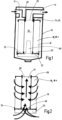
- the Fig. 1 shows, in the form of a longitudinal section in a highly simplified form, the filter device according to the invention as a whole.
- the filter device has a filter housing 10, which has an inlet 12 for unfiltered material and an outlet 14 for filtrate.
- a replaceable filter element 16 is accommodated in the filter housing 10, through which unfiltered material flows from the outside to the inside, as shown in the Fig. 2 , both a hollow cylindrical element material 18 and an element material 22 closing this hollow cylinder 18a at its one free end 20.
- a corresponding central recess 29 is formed by the free end of the hollow cylinder 18a ( Fig. 2 ).
- a head-end housing section must be separated from a base- or pot-end housing section with the filter element 16. This is common practice, so it will not be discussed in detail here.
- the upper element cap 26 is pushed over a nozzle as part of the outlet 14 and sealed in this area by a sealing ring 30 on the housing side, which serves as the sole seal between the element 16 and the housing 10. Otherwise, the respective element material 18, 22 for an all-round flow from outside to inside according to the representation according to the Fig. 2 , sealing-free according to the representation according to the Fig. 1 in the filter housing 10. In particular, there is no seal in the bottom area of the filter housing 10 opposite the final element material 22.
- the closing element material 22 is accommodated in a foot- or bottom-side end cap 32, which, designed as a type of double receptacle, serves simultaneously to secure the closed, disc-shaped element material 22 and the hollow-cylindrical element material 18.
- the accommodation of corresponding element material of a filter element 16 in end caps closing the element is known, so it will not be discussed in more detail here.
- the element material 18, 22 of the filter element 16 is preferably constructed entirely of cellulose material, i.e., both the hollow-cylindrical element material 18 and the closed closing element material 22.
- closed in the sense of the application means that the closing element material 22 is indeed continuously porous; but otherwise has no fluid passages, such as fluid-carrying throttle passages, which could connect the environment with the hollow cylindrical interior 34 of the hollow cylinder 18a.
- the unfiltered material is introduced exclusively via the porosity of the element material 22 for passage into the interior 34 of the element 16.
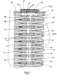
- the hollow cylinder 18a of the filter element 16 consists of individual, preferably identical, annular filter discs 36, which are arranged one above the other or in a stacked sequence and are firmly connected to one another, preferably glued, at their adjacent end faces.
- the filter disc 36 arranged at the bottom as the element material 22 closing the free end of the hollow cylinder 18a is not accommodated in an additional end cap 32, but rather is firmly connected, in particular firmly glued or firmly welded, directly to the lowest filter disc 36 of the hollow cylindrical element material 18 in the stacking sequence.
- the filter disc 38 arranged at the very top forms a receiving possibility for the upper element cap 26 with the central recess 28, the boundary edge of which has a groove-shaped depression 40 for receiving the sealing ring 30 according to the illustration according to the Fig. 1 .
- the element cap 26 encompasses the outer edge of the uppermost filter disc 38 on the outer circumference and is firmly connected to it, for example by means of an adhesive connection.
- the individual filter discs 36 can also be formed from partial halves 36a, 36b which, viewed diametrically to the longitudinal axis of the filter element 16, have, between them, identically formed recesses 42 lying opposite one another, which are formed by notch-like incisions or embossings in the filter discs 36 or are designed so that two filter disc halves 36a, 36b of a filter disc 36 are adjacent to one another. Furthermore, in the stacking sequence between filter discs 36 there are corresponding further recesses 44 which are formed correspondingly to the recesses 42.
- the respective recess 42, 44 thus runs from a rectangular central region, tapering wedge-like at the edge, into the respective filter disc 36, or into the adjacently arranged disc halves 36, 36b.
- the aforementioned recesses 42, 44 in the form of incisions or impressions are arranged only on the upper side of the respective element material 18, 22 and do not engage in the hollow cylindrical interior 34 of the filter element 16.
- the possible flow directions of the filter element 16 are shown in the Fig. 3 again indicated by arrows, whereby for the lowest filter disc 36 in the stacking sequence a flow from the bottom side in the direction of the interior 34 of the filter element 16.
- the recesses 42, 44 are formed by corresponding circumferential impressions or incisions, whereby in each case the recesses 42, 44 reinforce the stability of the cellulose element as a whole and serve to improve the flow guidance for the unfiltered material flow from the outside into the interior 34 of the filter element 16.
- four recesses 42, 44 lying in a common radial plane are present in each filter disc 36 or between disc halves 36a, 36b of a filter disc 36.
- the disc-shaped element material 22, which is closed except for its porosity, is formed from a filter disc that originates from the sheet former.
- the individual disc halves 36a, 36b forming individual filter discs have radially extending limiting rods as spacers 46 facing one another, which define recesses 48 between them, which in turn serve to improve fluid guidance, but again do not completely penetrate the filtering material, comparable to the recesses 42, 44 according to the previously described embodiments.
- the interior space 34 can additionally, if necessary, also have a flow guiding or inlet device 50 which, for improved flow guidance in the interior of the filter element 16, has a trumpet shape whose largest cross section merges integrally into the element material of the closed lower filter disc 36.
- the solution according to the invention serves in particular to remove so-called varnish from a fluid stream, which is usually formed from oil aging products, which are not listed in the literature as "hard particles" and therefore do not constitute particulate contamination in the true sense.
- the application also relates to dewatering; in particular, cellulose has the property of being able to absorb water. This also allows for oil-water separation. Finally, particulate filtration is also possible.
Landscapes
- Chemical & Material Sciences (AREA)
- Chemical Kinetics & Catalysis (AREA)
- Life Sciences & Earth Sciences (AREA)
- Geology (AREA)
- Filtering Materials (AREA)
- Filtration Of Liquid (AREA)
- Piezo-Electric Or Mechanical Vibrators, Or Delay Or Filter Circuits (AREA)
- Thermistors And Varistors (AREA)
- Fixed Capacitors And Capacitor Manufacturing Machines (AREA)
- Filtering Of Dispersed Particles In Gases (AREA)
- Separation Using Semi-Permeable Membranes (AREA)
Priority Applications (1)
| Application Number | Priority Date | Filing Date | Title |
|---|---|---|---|
| EP25172652.7A EP4582162A3 (de) | 2021-05-20 | 2022-04-27 | Filtervorrichtung nebst einem darin aufnehmbaren filterelement und verfahren zum betrieb eines solchen filterelementes nebst vorrichtung |
Applications Claiming Priority (2)
| Application Number | Priority Date | Filing Date | Title |
|---|---|---|---|
| DE102021002647.0A DE102021002647A1 (de) | 2021-05-20 | 2021-05-20 | Filtervorrichtung nebst einem darin aufnehmbaren Filterelement und Verfahren zum Betrieb eines solchen Filterelementes nebst Vorrichtung |
| PCT/EP2022/061180 WO2022242994A1 (de) | 2021-05-20 | 2022-04-27 | Filtervorrichtung nebst einem darin aufnehmbaren filterelement und verfahren zum betrieb eines solchen filterelementes nebst vorrichtung |
Related Child Applications (2)
| Application Number | Title | Priority Date | Filing Date |
|---|---|---|---|
| EP25172652.7A Division EP4582162A3 (de) | 2021-05-20 | 2022-04-27 | Filtervorrichtung nebst einem darin aufnehmbaren filterelement und verfahren zum betrieb eines solchen filterelementes nebst vorrichtung |
| EP25172652.7A Division-Into EP4582162A3 (de) | 2021-05-20 | 2022-04-27 | Filtervorrichtung nebst einem darin aufnehmbaren filterelement und verfahren zum betrieb eines solchen filterelementes nebst vorrichtung |
Publications (3)
| Publication Number | Publication Date |
|---|---|
| EP4288177A1 EP4288177A1 (de) | 2023-12-13 |
| EP4288177C0 EP4288177C0 (de) | 2025-06-18 |
| EP4288177B1 true EP4288177B1 (de) | 2025-06-18 |
Family
ID=81654782
Family Applications (2)
| Application Number | Title | Priority Date | Filing Date |
|---|---|---|---|
| EP22723694.0A Active EP4288177B1 (de) | 2021-05-20 | 2022-04-27 | Filtervorrichtung nebst einem darin aufnehmbaren filterelement und verfahren zum betrieb eines solchen filterelementes nebst vorrichtung |
| EP25172652.7A Pending EP4582162A3 (de) | 2021-05-20 | 2022-04-27 | Filtervorrichtung nebst einem darin aufnehmbaren filterelement und verfahren zum betrieb eines solchen filterelementes nebst vorrichtung |
Family Applications After (1)
| Application Number | Title | Priority Date | Filing Date |
|---|---|---|---|
| EP25172652.7A Pending EP4582162A3 (de) | 2021-05-20 | 2022-04-27 | Filtervorrichtung nebst einem darin aufnehmbaren filterelement und verfahren zum betrieb eines solchen filterelementes nebst vorrichtung |
Country Status (8)
| Country | Link |
|---|---|
| US (1) | US20240216838A1 (enExample) |
| EP (2) | EP4288177B1 (enExample) |
| JP (1) | JP2024518037A (enExample) |
| CN (1) | CN117222462A (enExample) |
| AU (1) | AU2022277601A1 (enExample) |
| BR (1) | BR112023019845A2 (enExample) |
| DE (1) | DE102021002647A1 (enExample) |
| WO (1) | WO2022242994A1 (enExample) |
Families Citing this family (1)
| Publication number | Priority date | Publication date | Assignee | Title |
|---|---|---|---|---|
| DE102023001779B3 (de) | 2023-05-03 | 2024-11-07 | Hydac Filter Systems Gmbh | Abscheidevorrichtung |
Family Cites Families (8)
| Publication number | Priority date | Publication date | Assignee | Title |
|---|---|---|---|---|
| US3231094A (en) * | 1962-04-10 | 1966-01-25 | Wood Conversion Co | Filter element, unit, cartridge and insert |
| US4636231A (en) | 1985-08-15 | 1987-01-13 | Allied Corporation | Panel air filter |
| US4629474A (en) * | 1985-09-06 | 1986-12-16 | Allied Corporation | Thermally formed filter |
| US4732677A (en) | 1986-09-17 | 1988-03-22 | Allied Corporation | Thermally formed stacked disc filter |
| DE102012211185A1 (de) | 2012-06-28 | 2014-01-02 | Robert Bosch Gmbh | Flüssigkeitsfilter mit Dämpfungselement, sowie Filtereinsatz für einen Flüssigkeitsfilter |
| US10751650B2 (en) * | 2014-11-04 | 2020-08-25 | Winchester Global Pty Ltd | Bypass filter method and device |
| EP3130387A1 (en) | 2015-08-14 | 2017-02-15 | C.C. Jensen A/S | Oil filter comprising a hydraulic resistance |
| DE102016013166A1 (de) | 2016-11-04 | 2018-05-09 | Hydac Filter Systems Gmbh | Filterelement |
-
2021
- 2021-05-20 DE DE102021002647.0A patent/DE102021002647A1/de active Pending
-
2022
- 2022-04-27 CN CN202280031140.8A patent/CN117222462A/zh active Pending
- 2022-04-27 EP EP22723694.0A patent/EP4288177B1/de active Active
- 2022-04-27 JP JP2023564178A patent/JP2024518037A/ja active Pending
- 2022-04-27 BR BR112023019845A patent/BR112023019845A2/pt unknown
- 2022-04-27 AU AU2022277601A patent/AU2022277601A1/en active Pending
- 2022-04-27 US US18/562,813 patent/US20240216838A1/en active Pending
- 2022-04-27 WO PCT/EP2022/061180 patent/WO2022242994A1/de not_active Ceased
- 2022-04-27 EP EP25172652.7A patent/EP4582162A3/de active Pending
Also Published As
| Publication number | Publication date |
|---|---|
| JP2024518037A (ja) | 2024-04-24 |
| WO2022242994A1 (de) | 2022-11-24 |
| EP4582162A2 (de) | 2025-07-09 |
| EP4288177C0 (de) | 2025-06-18 |
| EP4288177A1 (de) | 2023-12-13 |
| DE102021002647A1 (de) | 2022-11-24 |
| EP4582162A3 (de) | 2025-09-10 |
| AU2022277601A1 (en) | 2023-11-23 |
| US20240216838A1 (en) | 2024-07-04 |
| BR112023019845A2 (pt) | 2023-12-05 |
| CN117222462A (zh) | 2023-12-12 |
Similar Documents
| Publication | Publication Date | Title |
|---|---|---|
| EP2649292B1 (de) | Kraftstofffilter | |
| EP2919879B1 (de) | Filterelement | |
| EP2762219B1 (de) | Becherförmiges Gehäuse und Vorrichtung zum Abscheiden von Flüssigkeit aus Luft | |
| DE102015103619A1 (de) | Vorrichtung zum Reinigen von flüssigen oder gasförmigen Medien und Abscheideelement für die Vorrichtung | |
| DE60207698T2 (de) | Filterpatrone für eine filteranordnung | |
| DE112007001880T5 (de) | Schnellablaßfilter | |
| DE102022203518A1 (de) | Ringfilterelement | |
| EP1996307A1 (de) | Filtereinsatz mit verschluss für zweite filterkammer | |
| EP3271040A1 (de) | Filtereinrichtung | |
| EP4288177B1 (de) | Filtervorrichtung nebst einem darin aufnehmbaren filterelement und verfahren zum betrieb eines solchen filterelementes nebst vorrichtung | |
| DE102007033337A1 (de) | Filterkartusche für eine Wasserfiltervorrichtung | |
| EP3278855A1 (de) | Filteranlage | |
| WO2019020467A1 (de) | Einweg-filtercapsule für eine filtrationsvorrichtung | |
| EP3684494A1 (de) | Filtervorrichtung | |
| EP4475975B1 (de) | Filtervorrichtung | |
| DE102013001843A1 (de) | Filterelement zum Filtern von Flüssigkeit, insbesondere von Harnstofflösung | |
| EP2481474B1 (de) | Dichtungsanordnung für stabförmige keramische Filterelemente | |
| WO2019042823A1 (de) | Koaleszerstufe eines filtereinsatzes eines kraftstofffilters, filtereinsatz und kraftstofffilter | |
| DE10352703A1 (de) | Filtervorrichtung | |
| EP1455921B1 (de) | Filtervorrichtung, insbesondere stapelfilter | |
| DE102017007270A1 (de) | Filterelement | |
| DE202006004529U1 (de) | Filtereinsatz mit Verschluss für zweite Filterkammer | |
| DE102015014728A1 (de) | Filterelement und System zum Filtern eines Fluids | |
| WO2022079116A1 (de) | Filtervorrichtung und abscheideeinrichtung | |
| DE102016209793A1 (de) | Filtermodul und Filtervorrichtung |
Legal Events
| Date | Code | Title | Description |
|---|---|---|---|
| STAA | Information on the status of an ep patent application or granted ep patent |
Free format text: STATUS: UNKNOWN |
|
| STAA | Information on the status of an ep patent application or granted ep patent |
Free format text: STATUS: THE INTERNATIONAL PUBLICATION HAS BEEN MADE |
|
| PUAI | Public reference made under article 153(3) epc to a published international application that has entered the european phase |
Free format text: ORIGINAL CODE: 0009012 |
|
| STAA | Information on the status of an ep patent application or granted ep patent |
Free format text: STATUS: REQUEST FOR EXAMINATION WAS MADE |
|
| 17P | Request for examination filed |
Effective date: 20230908 |
|
| AK | Designated contracting states |
Kind code of ref document: A1 Designated state(s): AL AT BE BG CH CY CZ DE DK EE ES FI FR GB GR HR HU IE IS IT LI LT LU LV MC MK MT NL NO PL PT RO RS SE SI SK SM TR |
|
| DAV | Request for validation of the european patent (deleted) | ||
| DAX | Request for extension of the european patent (deleted) | ||
| GRAP | Despatch of communication of intention to grant a patent |
Free format text: ORIGINAL CODE: EPIDOSNIGR1 |
|
| STAA | Information on the status of an ep patent application or granted ep patent |
Free format text: STATUS: GRANT OF PATENT IS INTENDED |
|
| INTG | Intention to grant announced |
Effective date: 20250207 |
|
| GRAS | Grant fee paid |
Free format text: ORIGINAL CODE: EPIDOSNIGR3 |
|
| GRAA | (expected) grant |
Free format text: ORIGINAL CODE: 0009210 |
|
| STAA | Information on the status of an ep patent application or granted ep patent |
Free format text: STATUS: THE PATENT HAS BEEN GRANTED |
|
| AK | Designated contracting states |
Kind code of ref document: B1 Designated state(s): AL AT BE BG CH CY CZ DE DK EE ES FI FR GB GR HR HU IE IS IT LI LT LU LV MC MK MT NL NO PL PT RO RS SE SI SK SM TR |
|
| REG | Reference to a national code |
Ref country code: GB Ref legal event code: FG4D Free format text: NOT ENGLISH |
|
| REG | Reference to a national code |
Ref country code: CH Ref legal event code: EP |
|
| REG | Reference to a national code |
Ref country code: DE Ref legal event code: R096 Ref document number: 502022004331 Country of ref document: DE |
|
| REG | Reference to a national code |
Ref country code: CH Ref legal event code: EP |
|
| REG | Reference to a national code |
Ref country code: IE Ref legal event code: FG4D Free format text: LANGUAGE OF EP DOCUMENT: GERMAN |
|
| U01 | Request for unitary effect filed |
Effective date: 20250618 |
|
| U07 | Unitary effect registered |
Designated state(s): AT BE BG DE DK EE FI FR IT LT LU LV MT NL PT RO SE SI Effective date: 20250626 |
|
| PG25 | Lapsed in a contracting state [announced via postgrant information from national office to epo] |
Ref country code: NO Free format text: LAPSE BECAUSE OF FAILURE TO SUBMIT A TRANSLATION OF THE DESCRIPTION OR TO PAY THE FEE WITHIN THE PRESCRIBED TIME-LIMIT Effective date: 20250918 Ref country code: GR Free format text: LAPSE BECAUSE OF FAILURE TO SUBMIT A TRANSLATION OF THE DESCRIPTION OR TO PAY THE FEE WITHIN THE PRESCRIBED TIME-LIMIT Effective date: 20250919 |
|
| PG25 | Lapsed in a contracting state [announced via postgrant information from national office to epo] |
Ref country code: HR Free format text: LAPSE BECAUSE OF FAILURE TO SUBMIT A TRANSLATION OF THE DESCRIPTION OR TO PAY THE FEE WITHIN THE PRESCRIBED TIME-LIMIT Effective date: 20250618 |
|
| PG25 | Lapsed in a contracting state [announced via postgrant information from national office to epo] |
Ref country code: RS Free format text: LAPSE BECAUSE OF FAILURE TO SUBMIT A TRANSLATION OF THE DESCRIPTION OR TO PAY THE FEE WITHIN THE PRESCRIBED TIME-LIMIT Effective date: 20250918 |
|
| PG25 | Lapsed in a contracting state [announced via postgrant information from national office to epo] |
Ref country code: IS Free format text: LAPSE BECAUSE OF FAILURE TO SUBMIT A TRANSLATION OF THE DESCRIPTION OR TO PAY THE FEE WITHIN THE PRESCRIBED TIME-LIMIT Effective date: 20251018 |
|
| PG25 | Lapsed in a contracting state [announced via postgrant information from national office to epo] |
Ref country code: SM Free format text: LAPSE BECAUSE OF FAILURE TO SUBMIT A TRANSLATION OF THE DESCRIPTION OR TO PAY THE FEE WITHIN THE PRESCRIBED TIME-LIMIT Effective date: 20250618 |
|
| PG25 | Lapsed in a contracting state [announced via postgrant information from national office to epo] |
Ref country code: CZ Free format text: LAPSE BECAUSE OF FAILURE TO SUBMIT A TRANSLATION OF THE DESCRIPTION OR TO PAY THE FEE WITHIN THE PRESCRIBED TIME-LIMIT Effective date: 20250618 |
|
| PG25 | Lapsed in a contracting state [announced via postgrant information from national office to epo] |
Ref country code: PL Free format text: LAPSE BECAUSE OF FAILURE TO SUBMIT A TRANSLATION OF THE DESCRIPTION OR TO PAY THE FEE WITHIN THE PRESCRIBED TIME-LIMIT Effective date: 20250618 |
|
| PG25 | Lapsed in a contracting state [announced via postgrant information from national office to epo] |
Ref country code: SK Free format text: LAPSE BECAUSE OF FAILURE TO SUBMIT A TRANSLATION OF THE DESCRIPTION OR TO PAY THE FEE WITHIN THE PRESCRIBED TIME-LIMIT Effective date: 20250618 |
|
| PG25 | Lapsed in a contracting state [announced via postgrant information from national office to epo] |
Ref country code: ES Free format text: LAPSE BECAUSE OF FAILURE TO SUBMIT A TRANSLATION OF THE DESCRIPTION OR TO PAY THE FEE WITHIN THE PRESCRIBED TIME-LIMIT Effective date: 20250618 |
|
| PGFP | Annual fee paid to national office [announced via postgrant information from national office to epo] |
Ref country code: GB Payment date: 20260319 Year of fee payment: 5 |
|
| PLBE | No opposition filed within time limit |
Free format text: ORIGINAL CODE: 0009261 |
|
| STAA | Information on the status of an ep patent application or granted ep patent |
Free format text: STATUS: NO OPPOSITION FILED WITHIN TIME LIMIT |
|
| REG | Reference to a national code |
Ref country code: CH Ref legal event code: L10 Free format text: ST27 STATUS EVENT CODE: U-0-0-L10-L00 (AS PROVIDED BY THE NATIONAL OFFICE) Effective date: 20260430 |