EP4286801A1 - Sensorvorrichtung und kondensatabwasserabfuhrvorrichtung mit einer sensorvorrichtung - Google Patents
Sensorvorrichtung und kondensatabwasserabfuhrvorrichtung mit einer sensorvorrichtung Download PDFInfo
- Publication number
- EP4286801A1 EP4286801A1 EP23175554.7A EP23175554A EP4286801A1 EP 4286801 A1 EP4286801 A1 EP 4286801A1 EP 23175554 A EP23175554 A EP 23175554A EP 4286801 A1 EP4286801 A1 EP 4286801A1
- Authority
- EP
- European Patent Office
- Prior art keywords
- sensor
- reservoir
- water
- light
- sensor device
- Prior art date
- Legal status (The legal status is an assumption and is not a legal conclusion. Google has not performed a legal analysis and makes no representation as to the accuracy of the status listed.)
- Granted
Links
Images

Classifications
-
- F—MECHANICAL ENGINEERING; LIGHTING; HEATING; WEAPONS; BLASTING
- F24—HEATING; RANGES; VENTILATING
- F24F—AIR-CONDITIONING; AIR-HUMIDIFICATION; VENTILATION; USE OF AIR CURRENTS FOR SCREENING
- F24F13/00—Details common to, or for air-conditioning, air-humidification, ventilation or use of air currents for screening
- F24F13/22—Means for preventing condensation or evacuating condensate
- F24F13/222—Means for preventing condensation or evacuating condensate for evacuating condensate
-
- G—PHYSICS
- G01—MEASURING; TESTING
- G01V—GEOPHYSICS; GRAVITATIONAL MEASUREMENTS; DETECTING MASSES OR OBJECTS; TAGS
- G01V8/00—Prospecting or detecting by optical means
- G01V8/10—Detecting, e.g. by using light barriers
- G01V8/12—Detecting, e.g. by using light barriers using one transmitter and one receiver
-
- G—PHYSICS
- G01—MEASURING; TESTING
- G01F—MEASURING VOLUME, VOLUME FLOW, MASS FLOW OR LIQUID LEVEL; METERING BY VOLUME
- G01F23/00—Indicating or measuring liquid level or level of fluent solid material, e.g. indicating in terms of volume or indicating by means of an alarm
- G01F23/0007—Indicating or measuring liquid level or level of fluent solid material, e.g. indicating in terms of volume or indicating by means of an alarm for discrete indicating and measuring
-
- F—MECHANICAL ENGINEERING; LIGHTING; HEATING; WEAPONS; BLASTING
- F24—HEATING; RANGES; VENTILATING
- F24F—AIR-CONDITIONING; AIR-HUMIDIFICATION; VENTILATION; USE OF AIR CURRENTS FOR SCREENING
- F24F11/00—Control or safety arrangements
- F24F11/30—Control or safety arrangements for purposes related to the operation of the system, e.g. for safety or monitoring
-
- F—MECHANICAL ENGINEERING; LIGHTING; HEATING; WEAPONS; BLASTING
- F25—REFRIGERATION OR COOLING; COMBINED HEATING AND REFRIGERATION SYSTEMS; HEAT PUMP SYSTEMS; MANUFACTURE OR STORAGE OF ICE; LIQUEFACTION SOLIDIFICATION OF GASES
- F25D—REFRIGERATORS; COLD ROOMS; ICE-BOXES; COOLING OR FREEZING APPARATUS NOT OTHERWISE PROVIDED FOR
- F25D21/00—Defrosting; Preventing frosting; Removing condensed or defrost water
- F25D21/14—Collecting or removing condensed and defrost water; Drip trays
-
- G—PHYSICS
- G01—MEASURING; TESTING
- G01F—MEASURING VOLUME, VOLUME FLOW, MASS FLOW OR LIQUID LEVEL; METERING BY VOLUME
- G01F22/00—Methods or apparatus for measuring volume of fluids or fluent solid material, not otherwise provided for
-
- G—PHYSICS
- G01—MEASURING; TESTING
- G01F—MEASURING VOLUME, VOLUME FLOW, MASS FLOW OR LIQUID LEVEL; METERING BY VOLUME
- G01F23/00—Indicating or measuring liquid level or level of fluent solid material, e.g. indicating in terms of volume or indicating by means of an alarm
- G01F23/22—Indicating or measuring liquid level or level of fluent solid material, e.g. indicating in terms of volume or indicating by means of an alarm by measuring physical variables, other than linear dimensions, pressure or weight, dependent on the level to be measured, e.g. by difference of heat transfer of steam or water
- G01F23/28—Indicating or measuring liquid level or level of fluent solid material, e.g. indicating in terms of volume or indicating by means of an alarm by measuring physical variables, other than linear dimensions, pressure or weight, dependent on the level to be measured, e.g. by difference of heat transfer of steam or water by measuring the variations of parameters of electromagnetic or acoustic waves applied directly to the liquid or fluent solid material
- G01F23/284—Electromagnetic waves
- G01F23/292—Light, e.g. infrared or ultraviolet
- G01F23/2921—Light, e.g. infrared or ultraviolet for discrete levels
- G01F23/2922—Light, e.g. infrared or ultraviolet for discrete levels with light-conducting sensing elements, e.g. prisms
- G01F23/2925—Light, e.g. infrared or ultraviolet for discrete levels with light-conducting sensing elements, e.g. prisms using electrical detecting means
-
- G—PHYSICS
- G01—MEASURING; TESTING
- G01V—GEOPHYSICS; GRAVITATIONAL MEASUREMENTS; DETECTING MASSES OR OBJECTS; TAGS
- G01V8/00—Prospecting or detecting by optical means
- G01V8/10—Detecting, e.g. by using light barriers
- G01V8/20—Detecting, e.g. by using light barriers using multiple transmitters or receivers
-
- G—PHYSICS
- G01—MEASURING; TESTING
- G01V—GEOPHYSICS; GRAVITATIONAL MEASUREMENTS; DETECTING MASSES OR OBJECTS; TAGS
- G01V8/00—Prospecting or detecting by optical means
- G01V8/10—Detecting, e.g. by using light barriers
- G01V8/20—Detecting, e.g. by using light barriers using multiple transmitters or receivers
- G01V8/22—Detecting, e.g. by using light barriers using multiple transmitters or receivers using reflectors
-
- G—PHYSICS
- G01—MEASURING; TESTING
- G01V—GEOPHYSICS; GRAVITATIONAL MEASUREMENTS; DETECTING MASSES OR OBJECTS; TAGS
- G01V9/00—Prospecting or detecting by methods not provided for in groups G01V1/00 - G01V8/00
-
- F—MECHANICAL ENGINEERING; LIGHTING; HEATING; WEAPONS; BLASTING
- F24—HEATING; RANGES; VENTILATING
- F24F—AIR-CONDITIONING; AIR-HUMIDIFICATION; VENTILATION; USE OF AIR CURRENTS FOR SCREENING
- F24F13/00—Details common to, or for air-conditioning, air-humidification, ventilation or use of air currents for screening
- F24F13/22—Means for preventing condensation or evacuating condensate
-
- F—MECHANICAL ENGINEERING; LIGHTING; HEATING; WEAPONS; BLASTING
- F24—HEATING; RANGES; VENTILATING
- F24F—AIR-CONDITIONING; AIR-HUMIDIFICATION; VENTILATION; USE OF AIR CURRENTS FOR SCREENING
- F24F13/00—Details common to, or for air-conditioning, air-humidification, ventilation or use of air currents for screening
- F24F13/22—Means for preventing condensation or evacuating condensate
- F24F13/222—Means for preventing condensation or evacuating condensate for evacuating condensate
- F24F2013/227—Condensate pipe for drainage of condensate from the evaporator
-
- F—MECHANICAL ENGINEERING; LIGHTING; HEATING; WEAPONS; BLASTING
- F24—HEATING; RANGES; VENTILATING
- F24F—AIR-CONDITIONING; AIR-HUMIDIFICATION; VENTILATION; USE OF AIR CURRENTS FOR SCREENING
- F24F13/00—Details common to, or for air-conditioning, air-humidification, ventilation or use of air currents for screening
- F24F13/22—Means for preventing condensation or evacuating condensate
- F24F2013/228—Treatment of condensate, e.g. sterilising
-
- F—MECHANICAL ENGINEERING; LIGHTING; HEATING; WEAPONS; BLASTING
- F24—HEATING; RANGES; VENTILATING
- F24F—AIR-CONDITIONING; AIR-HUMIDIFICATION; VENTILATION; USE OF AIR CURRENTS FOR SCREENING
- F24F2140/00—Control inputs relating to system states
- F24F2140/30—Condensation of water from cooled air
-
- F—MECHANICAL ENGINEERING; LIGHTING; HEATING; WEAPONS; BLASTING
- F25—REFRIGERATION OR COOLING; COMBINED HEATING AND REFRIGERATION SYSTEMS; HEAT PUMP SYSTEMS; MANUFACTURE OR STORAGE OF ICE; LIQUEFACTION SOLIDIFICATION OF GASES
- F25D—REFRIGERATORS; COLD ROOMS; ICE-BOXES; COOLING OR FREEZING APPARATUS NOT OTHERWISE PROVIDED FOR
- F25D21/00—Defrosting; Preventing frosting; Removing condensed or defrost water
- F25D21/02—Detecting the presence of frost or condensate
Definitions
- the present invention belongs to the field of sensor device for the detection of water and condensate water removal devices in combination with such sensor devices.
- ⁇ HVACR systems Devices, systems and equipment from the field of heating, ventilation, air conditioning and refrigeration - which are collectively referred to as ⁇ HVACR systems' throughout this document - comprise refrigeration cycles with condenser units or similar units. These condensers tend to produce condensate water, which is typically collected by a so-called drip tray or condensate water tray, that is arranged below the condenser.
- HVACCR systems shall apply in particular, but not exclusively, to any kind of air conditioners, (gas) heaters, thermal heat pumps, condensing (gas) boilers, and so on.
- the drip tray may be manually removable so that a user may empty the drip tray periodically.
- Other units especially those with nonremovable drip trays, support the removal of the condensate water via a drain.
- a condensate water hose also referred to as condensate water tube or pipe
- condensate water tube or pipe will be connected to a drain port of the drip tray and condensate water is removed via this hose.
- a condensate water pump needs to be connected to the condensate water hose. It will pump the condensate water out of the drip tray and towards a drain.
- condensate water pumps are known in the field from many different manufacturers. To improve efficiency and extend service life of the condensate water pump, it is well-known that it is particularly useful to combine a condensate water pump with a means to sense the presence of condensate water or even the amount of present condensate water or to incorporate such means with the condensate water pump. Such devices are referred to as ⁇ condensate water removal devices' throughout this document.
- a sensor device for detection of water comprises an inlet connector with an inlet opening, and at least one sensor element.
- the inlet connector is exposed to or connected to a source of water, e.g. the inlet connector may be adapted to sealingly fit into a condensate water hose or a drain port of a drip tray of an HVACR system.
- the inlet opening forms at least a part of a reservoir for reception of the water from the source of water. That the reservoir forms ⁇ at least a part' of the reservoir means that the inlet opening may be in direct fluidic connection with other volumes, e.g. like condensate water hoses or chambers of housings as explained further down below, that form the reservoir together.
- a larger reservoir can be used, therefore increasing the amount of water that can be received and temporarily stored in the reservoir.
- a condensate water removal device which incorporates the sensor device, may be operated more efficiently, as a larger amount of water can be removed from the reservoir at once and a pump unit of the condensate water removal device can then be turned off for a longer period of time, until a certain amount of water has again accumulated in the larger reservoir.
- the reservoir could also be formed by the inlet opening alone, therefore minimizing the size of the sensor device.
- the response time of the sensor device can be reduced, as a small reservoir which is formed by the inlet opening alone, will only need to receive a small amount of water until a detectable filling level is reached.
- the reservoir may be in fluid communication with a venting means, that vents the reservoir to the surrounding air, therefore preventing a siphon effect of the sensor device.
- the above-mentioned venting means is a small vent that is directly comprised by the sensor device, e.g. directly connected to the inlet connector.
- the venting means is not comprised by the sensor device itself, but is nevertheless in fluid communication with the reservoir.
- the sensor element is positioned within or adjacent to the inlet opening such that it protrudes into the reservoir or forms an interface of the reservoir. Therefore, the dimensions of the sensor device are basically given by the dimensions of the inlet connector, i.e. the sensor device is very small, light in weight and can be used in many applications, as explained further down below with exemplary embodiments of the sensor device. Neither the sensor device nor any superordinate unit, e.g. a condensate water removal device that comprises the sensor device, requires a housing that incorporates a sensor and/or a distinct reservoir.
- the sensor element in particular in an embodiment wherein the reservoir is formed not alone by the inlet opening, is generally positioned within or adjacent to the reservoir, i.e. any part of the reservoir and not necessarily that part, which is formed by the inlet opening. That way, the sensor element can be positioned more flexibly, the exchange and/or maintenance of the sensor device or sensor element is easier and a wider variety of sensor devices can be used, as they do not need to fit into the inlet opening.
- the sensor device comprises at least two sensor elements, particularly three sensor elements, which are positioned at different locations within or adjacent to the inlet opening and/or the reservoir. Therefore, the sensor device not only is able to detect the presence or absence of water at the position of one sensor element, but it is able to detect water at several locations. Particularly, the sensor elements are distributed along a measuring axis. That enables the sensor device to detect the rise and fall of the water level relative to that measuring axis, therefore the sensor element can determine the amount of water present in the reservoir.
- the reservoir is formed at least in part by the inlet opening of the inlet connector and by an internal volume of a first condensate water hose.
- the condensate water hose is connected with one end to the inlet opening of the sensor device, therefore the internal volume of the hose is in direct fluidic connection with the inlet opening.
- the other end of the first condensate water hose is connected to a source of water, e.g. a drain port of a drip tray of an HVACR system.
- the width of the inlet opening covers at least 50%, in particular at least 75% or 85%, of the width or diameter of the internal volume of first condensate water hose.
- the first condensate water hose may be detachably connected to the sensor device, which enables a quick replacement of the hose and/or the compatibility to hoses of different length.
- the condensate water hose may alternatively be integrally formed with the inlet connector, therefore reducing the risk of leaks.
- the above-mentioned condensate water hose comprises a corrugated hose section.
- Such corrugated hose section is particularly reliable, as it can be bend in different directions easily, however, it is much less likely to kink compared to non-corrugate hoses.
- the corrugate hose section is also extensible, therefore being adaptable to even more different installation situations.
- the first condensate water hose comprises a filtering device.
- the filtering device comprises a small sponge, which is pushed into the hose, preferably near a distal end of the hose.
- the condensate water hose comprises a proximal end section adapted to connect to the inlet connector and a distal end section adapted to connect to a source of condensate water, e.g. a drain port of a drip tray.
- the distal end section comprises at least two connector sections with different opening widths, that adjoin each other.
- the connector sections are removably attached to the condensate water hose and/or each other.
- the hose is made of rubber and the opening widths of the connector sections get smaller starting from the distal end.
- the inlet connector is arranged on a first housing of a condensate water removal device.
- the first housing comprises an internal chamber, which is arranged adjacent to and in direct fluidic communication with the inlet opening.
- the reservoir is at least in part formed by the inlet opening and the internal chamber.
- the sensor element is not positioned within or adjacent to the inlet opening, but instead within or adjacent to the internal chamber of the housing, thereby satisfying the requirement of being positioned within or adjacent to the reservoir, as explained with respect to an alternative embodiment of the invention.
- the benefits of a larger reservoir are combined with a still very small first housing, as the internal chamber of the housing does not have to form the reservoir of a desired size on its own. Instead, internal chamber and inlet opening form the reservoir together. Additionally, the sensor element or multiple sensor elements can be arranged within or adjacent to the internal chamber more conveniently.
- the condensate water removal devices come in several different shapes and forms.
- the first housing may be the housing of a sensor unit, whereas a second housing may form a pump unit and comprises a pump to remove the water. Both units are connected via a second condensate water hose, such that the pump is in fluidic connection with the reservoir.
- the condensate water removal device may comprise only the first housing, wherein a pump is also integrated into the housing and in fluid communication with the reservoir / internal chamber via an internal fluid line.
- a pump is also integrated into the housing and in fluid communication with the reservoir / internal chamber via an internal fluid line.
- Such devices can be of the type of a submersible pump, wherein water enters the reservoir simply through the inlet opening as the device is submersed in water.
- the device may be used similar to the above-mentioned split pump devices, i.e. being connectable to a source of water via a first condensate water hose that connects to the inlet connector of the sensor device.
- the condensate water removal device can be designed with very small size. That in turn means that it can be used in a very flexible and versatile way.
- the sensor element is adapted to generate an electric sensor signal, wherein the electric sensor signal is indicative of at least one of a presence or absence of water at a sensing surface of the sensor element, a pressure of a fluid in contact with the sensor element, a temperature of a fluid in contact with the sensor element, a thermal capacity of a fluid in contact with the sensor element, or a conductivity of a fluid in contact with the sensor elements.
- the sensor device is able to detect water reliably and the detection information can be processed easily by an electronics unit, that is connected to the sensor element and receives the electronic sensor signal.
- the at least one sensor element is an optical sensor.
- the sensor device comprises a transparent sensor body, which is arranged adjacent to the reservoir and comprises a prism-shaped or conical-shaped reflection face, which is facing towards the reservoir and is in contact with it.
- the at least one optical sensor comprises a set of one light emitter and one corresponding light receiver.
- the light receiver may be an LED (light emitting diode) and the light receiver may be a photo diode.
- the light emitter and light receiver are arranged adjacent to or integrated into a back surface of the sensor body, wherein the back surface is essentially opposite to the reflection face. Essentially opposite means that, while the reflection face faces towards the reservoir, the back surface faces away from it and is not in contact with it.
- the reflection face as well as the back surface may each comprise two or more surface sections with different orientation and none of the surface sections need to be parallel to another.
- the arrangement only needs to allow that the light of the light emitter is directed towards at least a section of the reflection face and the light receiver is positioned to receive light that is internally reflected back from the reflection face.
- the light receiver then provides an electronic sensor signal that is indicative of an amount of light reflected back from the reflection face. If no water is present at the position where the light from the light emitter is reflected, a majority of or essentially all of the light is reflected by internal total reflection. However, if water is present at the reflection face, the conditions of internal total reflection are not met and only a substantially lower amount of light is reflected towards the light receiver.
- An electronics unit is connected to the sensor element and is adapted to determine whether water is present or absent at the reflection face, based on the electronic sensor signal of the light receiver.
- the electronics unit may be part of the sensor device, e.g. on a printed circuit board of the sensor device. Particularly, the printed circuit board carries the light receiver, the light emitter and the electronic circuitry of the electronics unit at the same time.
- the electronics unit may as well be part of a superordinate unit, like a condensate water removal device that comprises the sensor device.
- the optical sensor of this embodiment is particularly useful, as it is reliable, accurate, highly integrateable, small in size and low in energy consumption.
- the sensor device comprises at least two optical sensors, wherein each one of the optical sensors comprises a set of one light emitter and one corresponding light receiver.
- the optical sensors do not utilise a separate sensor body each, but instead the sensor device comprises only one sensor body which has an elongate shape and extends along or in parallel to a measuring axis, along which the sensor elements are to be distributed.
- Each set of light emitters and light receivers is arranged adjacent to or integrated into a back surface of that one sensor body, which is essentially opposite to the reflection face, facing away from the reservoir, wherein the sets are positioned at different measuring positions along the measuring axis.
- the light of each one of the light emitters is directed towards an individual section of the reflection face of the sensor body and the light receivers provide electronic sensor signals that are indicative of an amount of light internally reflected back from the reflection face and received by the light receivers.
- the electronics unit is connected to the sensor elements and is adapted to determine whether water is present or absent at each measuring position at the reflection face, based on the electronic sensor signals of the light receivers.
- the optical sensors of this embodiment are particularly useful, as they are reliable, accurate, highly integrateable and low in energy consumption.
- the integration of multiple sets of light emitters and light receivers into the back surface of one "shared" sensor body at different positions results in a very small and robust design, while enabling the sensor device to detect the presence or absence at multiple positions along the measuring axis. Therefore, the sensor device can be used as a level sensor.
- the reflection face of the sensor body of the above-mentioned optical sensor or sensors is coated with a mould-reducing compound or material; ⁇ coated with' means that there is a layer of that material on top of the surface that is directed to and in contact with the reservoir or that the mould-reducing compound is directly integrated into the material of the sensor body.
- the mould-reducing compound may be any antimicrobial agent, that is suitable to reduce or eliminate growth of algae, mould and/or bacteria. Therefore, the sensor body of the sensor device needs to be cleaned much less frequently, as the functionality of the optical sensor or optical sensors will be much less effected by growth of algae, mould and/or bacteria.
- At least one optical sensor comprises a light emitter, that emits light of a wavelength of 500 nm to 550 nm or light of the near infrared spectrum.
- Light of that wavelength ranges is known to be harmful or at least not promotive to the growth of some algae, as that wavelengths cannot be absorbed by them as good as other wavelengths. Therefore, the growth of algae on the reflection face of the sensor body and any other surfaces that may be illuminated by the light emitter is effectively prohibited or at least reduced.
- the sensor device comprises at least one shield that is arranged in between of the light emitter and the light receiver of at least one optical sensor and/or in between the sets of lights emitters and light receivers of different optical sensors.
- the shield protrudes into the back surface of the sensor body, at least in part. The shield or multiple shields can effectively reduce the amount of stray light received by the light receivers, therefore increasing sensitivity and accuracy of the optical sensors.
- the inlet connector and/or the condensate water hose and/or the first housing of a condensate water removal device that comprises the sensor device are/is formed by an essentially non-transparent and non-translucent material; ⁇ essentially non-transparent and non-translucent' means that the material shall be able to effectively reduce the amount of light from the environment that reaches the light receivers, particularly by at least 50% or more. Particularly, the material is non-transparent and non-translucent for all wavelengths, which can be sensed by the light receivers.
- the sensor device comprises an UV-light emitter, that is adapted to emit ultra violet light onto the at least one sensor element. With the UV-light emitter directed onto the sensor element the sensor element is kept free of mould and/or algae.
- an electronics unit controls the UV-light emitter to emit light onto the at least one sensor element periodically.
- the electronics unit may be connected to the UV-light emitter and to the at least one sensor element and may be adapted to control the UV-light emitter to emit light onto the at least one sensor element only when the presence of water in the reservoir is detected based on a signal of the at least one sensor element.
- This embodiment is particularly advantageous, when the sensor device comprises an optical sensor and a transparent sensor body as described above.
- the UV-light emitter may be arranged directly next to the light emitters and light receivers of the optical sensor on the same substrate. Thus, the transparent sensor body can be illuminated from behind.
- the UV-light is also totally internally reflected.
- the sterilizing effect would be nil.
- the emission of UV light only when there is water ensures that even with the described optical sensors the UV light really hits the surfaces that come into contact with water or penetrates it and that the water itself and other surfaces within the reservoir can also be irradiated.
- the sensor device comprises an outlet port to connect the sensor device with other devices, for example a condensate water removal device as explained below.
- the outlet port is arranged at an end surface of an intake pipe, wherein the end surface is tilted by 30 ° with respect to a horizontal plane. Tests have shown that this angle between the normal to the water surface and the intake opening produces significantly less noise and/or vibration when the water is sucked in.
- the intake pipe is L-shaped and arranged rotatably in a socket on an inner wall of the reservoir.
- the intake pipe can be adapted to different orientations of the device.
- the inlet connector of the sensor device is arranged on the first housing
- the pump unit is adapted to pump water out of the reservoir of the sensor device via a fluid channel system that is connected to an outlet port of the reservoir and towards the outlet connector
- the electronics unit is electronically connected to the sensor element and adapted to determine a presence or absence of water and/or a level of water within the reservoir, and to provide a control signal, based on said detected presence and/or level of condensate water, to the pump unit.
- the sensor device of the present invention By the use of the sensor device of the present invention, all benefits and advantages of that sensor device transfer to the condensate water removal device, i.e. it is very reliable, small in size, lightweight, has a low energy consumption and can detect the presence and/or level of water inside the reservoir accurately.
- the outlet port is directly located adjacent to the inlet opening of the inlet connector. That arrangement contributes to a very small and light design of the condensate water removal device.
- the reservoir is further formed at least in part by an internal chamber of the first housing, which is arranged adjacent to and in fluid communication with the inlet opening of the inlet connector.
- the outlet port is located adjacent to that internal chamber.
- the above mentioned first housing and/or the internal chamber has or have a rectangular or square cross-section.
- the measuring axis of the sensor device extends along a diagonal line of the cross-section.
- the outlet port of the reservoir is positioned at one of the ends of the diagonal line.
- the condensate water removal device can be operated in two different orientations, i.e. with either one of the two housing sides, that are adjacent to that corner, on the ground. Therefore, the device can easily adapt to different spatial requirements of a given application. In both orientations, the outlet port will be close to the lowest point of the reservoir, allowing for an efficient removal of water by the pump unit through the outlet port.
- the pump unit is incorporated into the first housing, wherein a pump inlet is connected to the outlet port of the reservoir via the fluid channel system within the first housing.
- a pump inlet is connected to the outlet port of the reservoir via the fluid channel system within the first housing.
- Such devices can be of the type of a submersible pump, wherein water enters the reservoir simply through the inlet opening as the device is submersed in water.
- the device may be used similar to the above-mentioned split pump devices, i.e. being connectable to a source of water via a first condensate water hose that connects to the inlet connector of the sensor device.
- the condensate water removal device can be designed with very small size. That in turn means that it can be used in a very flexible and versatile way.
- the first housing may be the housing of only a sensor unit, whereas the pump unit is arranged within a second housing of the condensate water removal device. Both units are connected via a second condensate water hose, such that an inlet of the pump is in fluidic connection with the outlet port of the reservoir.
- the condensate water removal device is of the type of a split pump device, and therefore particularly easy to repair and adaptable to certain spatial requirements of different applications.
- the outlet port is arranged at an end surface of an intake pipe, wherein the end surface is tilted by 30 ° with respect to a horizontal plane. Tests have shown that this angle between the normal to the water surface and the intake opening produces significantly less noise and/or vibration when the water is sucked in.
- the intake pipe is L-shaped and arranged rotatably in a socket on an inner wall of the reservoir.
- the intake pipe can be adapted to different orientations of the device.
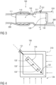
- FIGS 1, 2 and 3 show sectional views of exemplary embodiments of a sensor device 100 of the present invention.
- an inlet connector 110 with an inlet opening 111 at its distal end is connected to a first housing 310 of, e.g., a condensate water removal device 300 (not shown). From the inlet opening 111 a bore extends further inside the inlet connector 110, forming a reservoir 130, to receive water from a source of water.
- a sensor element 120 is arranged adjacent to or within the reservoir 130 to sense the presence and/or amount of water inside the reservoir 130. Possible electrical connections to other elements like, e.g., to an electronics unit, are not shown in this figure.
- the inlet connector 110 further comprises a venting means 131 close to or at a top side of the sensor device 100 to prevent a siphon effect.
- the sensor device 100 Close to or at a deepest point of the reservoir 130, the sensor device 100 comprises an outlet port 132 through which the reservoir 130 is in fluid communication with a fluid channel system 360, e.g., of the condensate water removal device 300.
- the inlet connector 110 of figure 1 is of cylindrical shape and small enough in diameter, so that condensate water hoses (not shown), which are typically used to connect a drain port of a drip tray of a HVACR-system to a condensate water removal device 300 or a drain, can be plugged onto the inlet connector 110 easily.
- the inlet connector 110 may be in the shape of a ribbed hose nozzle.
- figure 2 shows a shorter inlet connector 110 with a wider diameter, to make room for a wider reservoir 130.
- a first condensate water hose 200 is shown connected to the inlet connector 110 and comprises a widened connection section 220, that fits to the inlet connector 110 and forms a part of the wider reservoir 130. Adj acent to that widened connection section 220 the hose 200 comprises a corrugated hose section 210, which allows for very flexible adaption to different installation geometries.
- Figure 3 shows an inlet connector 110 that is similar to that of figure 1 .
- the bore through the inlet connector 110 which extends from the inlet opening 111, meets with an internal chamber 311 of the first housing 310.
- the inlet opening 111 and the internal chamber 311 together form the reservoir 130. Venting means 131 and outlet port 132 are arranged at that internal chamber 311.
- Figure 4 shows a sectional view through sectional plane A, as indicated in figure 3 .
- the first housing 310 has a rectangular shape and the sensor element 120 is aligned along a measuring axis 126 that extends on a diagonal of the rectangular housing 310.
- the outlet port 132 is positioned in the lower right corner, while the venting means 131 is positioned at the top left corner.
- the first housing 310 may be installed in two different orientations: Either with the bottom side or the right side (in the perspective of this figure) on the ground, as indicated with arrows. In these two orientations, the venting means 131 will be at the highest point of the reservoir 130 and can provide for an effective prevention of a siphon effect, without spilling water.
- the sensor device 100 may comprise multiple sensor elements 120', 120", 120′′′ which are aligned at different positions along the measuring axis 126.
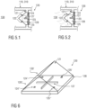
- Figures 5.1 and 5.2 show a section of a sensor device 100 with an optical sensor element 120.
- the sensor element 120 is arranged at and/or held by a wall section of the inlet connector 110 or first housing 310. It comprises a sensor body 121 with a prism shaped cross section. At a back surface 123 of the sensor body 121 a light emitter 124, a light receiver 125 and a shield 127 are arranged. The shield 127 protrudes into the sensor body 121 to effectively shield the light receiver 125 from stray light.
- a substrate 128, e.g. a PCB, is arranged to hold the shown components.
- the reservoir 130 is empty (or at least there is no water in close proximity to the sensor element 120).
- Light from the light emitter 124, as indicated by arrows, is directed towards a first reflection face 122.
- the material of the sensor body 121 i.e. its refractive index
- the angle of incidence of the light is chosen such that total internal reflection occurs at the internal side of the reflection face 122, when there is no water in contact with the outer side of the reflection face 122.
- the light is reflected towards a second reflection face 122, where another total internal reflection occurs, such that essentially all light from the light emitter 124 is eventually directed towards the light receiver 125.
- the reservoir 130 is filled with water (or at least a section of the reservoir 130 in close proximity to the sensor element 120).
- the Material i.e. its refractive index
- the angle of incidence are chosen such that the condition for total internal refraction is not met, when the outer side of the reflection face 122 is in contact with water.
- Substantial amounts of light will be refracted out of the sensor body 121, at both reflection faces 122.
- a much lower amount of light reaches the light receiver 125, as schematically indicated by the thin line of the arrow after the first reflection and the dotted line of the arrow after the second reflection.
- FIG. 6 shows a sensor element 120, which is an optical sensor with two sensor elements 120', 120" in a perspective view.
- Each sensor element 120', 120" comprises a set of a light emitter 124', 124" and a light receiver 125', 125".
- the two sets of light emitters 124', 124" and light receivers 125', 125" are arranged at different longitudinal positions on a back surface of a joint sensor body 121.
- a cross-shaped shield 127 shields the light receivers 125', 125" from stray light of the corresponding light emitter 124', 124" of the same set as well as from stray light of the light emitter 124', 124" of the respective other set.
- a substrate 128 is arranged to hold the shown components, i.e., the light emitters 124', 124", light receivers 125', 125” and the shield 127.
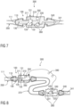
- FIGS 7 and 8 show exemplary embodiments of condensate water removal devices 300, each comprising an exemplary embodiment of the sensor device 100.
- the inlet connector 110 of the sensor device 100 is connected to a first housing 310 of the condensate water removal device 300.
- An inlet opening 111 and an internal chamber 311 of the housing 310 together form a reservoir 130 to receive water.
- a sensor element 120 is arranged adjacent to the reservoir 130.
- a venting means 131 is arranged at the internal chamber 311.
- An outlet port 132 connects the reservoir 130 to a fluid channel system 360.
- the condensate water removal device 300 further comprises a pump unit 330, an electronics unit 350 and an outlet connector 340 with an outlet hole 341.
- the inlet connector 110 is plugged into a first hose through which water is received from a source of water, e.g. a drain port of a drip tray.
- the outlet connector 340 is also connected to another hose, through which water can be pumped towards a drain.
- Figure 7 shows a setup than comprises only one housing 310 with sensor device 100, electronics unit 350 and pump unit 330 attached or integrated to it.
- the electronics unit 350 is adapted to evaluate the sensor signal of the sensor element 120 to determine a presence and/or a level of water present in the reservoir 130 and control the pump unit 330 to withdraw that water by way of the fluid channel system 360.
- figure 8 shows a setup with a first housing 310 and a second housing 320, which may be referred to as a split-pump design.
- the first housing 310 comprises the sensor device 100 and the electronics unit 350
- the second housing 320 comprises the pump unit 360 (and possible further electronics units, not shown).
- the fluid channel system 360 comprises a section that is formed by an intermediate hose 370.
- An electronic communication cable 380 is connected to both devices and provides for data and/or power transmission between the electronics units 350.
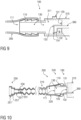
- Figure 9 schematically shows a sectional view of an exemplary embodiment of a sensor device 100 of the present invention, wherein the sensor device 100 comprises an inlet opening 111 at its distal end, which is connected to a first housing 310 of, e.g., a condensate water removal device 300 (not shown).
- the outlet port 132 is arranged at an end surface 134 of an L-shaped intake pipe 133.
- the intake pipe 133 is arranged rotatably in a socket on an inner wall of the reservoir 130.
- the intake pipe 133 can be adapted to different orientations of the sensor device 100.
- Figure 10 schematically shows a sectional view of a sensor device 100, wherein the sensor device 100 comprises an inlet opening 111 at its distal end, which is connected to a first housing 310 of, e.g., a condensate water removal device 300 (not shown).
- the sensor device 100 comprises a first condensate water hose 200 comprising a filtering device 230.
- the filtering device 230 comprises a small sponge 231, which is pushed into the hose 200 near a distal end 250 of the hose 200.
- the condensate water hose 200 comprises a proximal end section 240 adapted to connect to the inlet connector 110 and a distal end section 250 adapted to connect to a not shown source of condensate water.
- the distal end 250 section comprises at least two connector end sections 251, 251', 251" with different opening widths, that adjoin each other.
- the end sections 251, 251', 251" are removably attached to the condensate water hose 200 and/or each other.
- the hose 200 is made of rubber and the opening widths of the connector end sections 251, 251', 251" get smaller starting from the distal end 250.
- a user simply cuts off the sections that are too wide for a tight connection to a given source of water, for example with a carpet cutter.
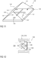
- Figure 11 schematically shows a sensor element 120, which is an optical sensor 120, in a perspective view.
- the optical sensor 120 further comprises an UV-light emitter 129, which is arranged on the substrate 128 with the light emitters 124', 124", light receivers 125', 125” and the shield 127.
- the UV-light emitter 129 is adapted to emit ultra violet light onto the sensor elements 120', 120". With the UV-light emitter 129 directed onto the sensor elements 120', 120" the sensor elements 120', 120"are kept free of mould and/or algae.
- the electronics unit 350 controls the UV-light emitter 129 to emit light onto the sensor elements 120', 120" periodically.
- the electronics unit 350 may be connected to the UV-light emitter 129 and to the sensor elements 120', 120" and may be adapted to control the UV-light emitter 129 to emit light onto the sensor elements 120', 120" only when the presence of water in the reservoir 130 is detected based on a signal of the sensor elements 120', 120".
- the UV-light emitter 129 is arranged directly next to the light emitters 124', 124" and light receivers 125', 125" of the optical sensor on the same substrate 128.
- the transparent sensor body 121 can be illuminated from behind.
- FIG. 12 schematically shows a sensor element 120, which is an optical sensor, adjacent to a reservoir 130 filled with water.
Landscapes
- Physics & Mathematics (AREA)
- Engineering & Computer Science (AREA)
- General Physics & Mathematics (AREA)
- Chemical & Material Sciences (AREA)
- Combustion & Propulsion (AREA)
- Mechanical Engineering (AREA)
- General Engineering & Computer Science (AREA)
- Electromagnetism (AREA)
- General Life Sciences & Earth Sciences (AREA)
- Geophysics (AREA)
- Thermal Sciences (AREA)
- Fluid Mechanics (AREA)
- Life Sciences & Earth Sciences (AREA)
- Investigating Or Analysing Materials By Optical Means (AREA)
- Measurement Of Levels Of Liquids Or Fluent Solid Materials (AREA)
Applications Claiming Priority (1)
| Application Number | Priority Date | Filing Date | Title |
|---|---|---|---|
| DE102022113588 | 2022-05-30 |
Publications (2)
| Publication Number | Publication Date |
|---|---|
| EP4286801A1 true EP4286801A1 (de) | 2023-12-06 |
| EP4286801B1 EP4286801B1 (de) | 2025-09-24 |
Family
ID=86604925
Family Applications (1)
| Application Number | Title | Priority Date | Filing Date |
|---|---|---|---|
| EP23175554.7A Active EP4286801B1 (de) | 2022-05-30 | 2023-05-26 | Sensorvorrichtung und kondensatabwasserabfuhrvorrichtung mit einer sensorvorrichtung |
Country Status (5)
| Country | Link |
|---|---|
| US (1) | US12535244B2 (de) |
| EP (1) | EP4286801B1 (de) |
| CN (1) | CN117148465A (de) |
| ES (1) | ES3057169T3 (de) |
| PL (1) | PL4286801T3 (de) |
Citations (6)
| Publication number | Priority date | Publication date | Assignee | Title |
|---|---|---|---|---|
| US5562003A (en) * | 1994-02-28 | 1996-10-08 | Sauermann Industrie | Apparatus for detecting the level of a liquid in a tank |
| US5765994A (en) * | 1995-07-14 | 1998-06-16 | Barbier; William J. | Low oil detector with automatic reset |
| JP2003262355A (ja) * | 2002-03-08 | 2003-09-19 | Saginomiya Seisakusho Inc | 水位検知器付き空気調和機用排水ポンプ |
| CN201247089Y (zh) * | 2008-08-22 | 2009-05-27 | 深圳市信威电子有限公司 | 一种两通管液位传感器 |
| US20180216871A1 (en) * | 2017-01-27 | 2018-08-02 | Robert Potorti | Portable air conditioner condensate handling assembly |
| US20180231412A1 (en) * | 2014-10-14 | 2018-08-16 | Aspen Pumps Limited | Liquid level detector |
Family Cites Families (5)
| Publication number | Priority date | Publication date | Assignee | Title |
|---|---|---|---|---|
| US4946242A (en) * | 1987-08-28 | 1990-08-07 | Hitachi, Ltd. | Optical part including integral combination of optical fiber and light emitting or receiving element and method of manufacturing the same |
| US20030097855A1 (en) * | 2001-11-28 | 2003-05-29 | Sergio Rovira-Adame | Drain tube for a refrigerator |
| US20090064698A1 (en) * | 2007-09-12 | 2009-03-12 | Spanger Gerald S | Condensate liquid pumping system |
| DE102012103651A1 (de) * | 2012-04-26 | 2013-10-31 | Leuze Electronic Gmbh + Co. Kg | Lichtvorhang |
| IT202000004219A1 (it) * | 2020-02-28 | 2021-08-28 | Aermec Spa | Ventilconvettore |
-
2023
- 2023-05-26 ES ES23175554T patent/ES3057169T3/es active Active
- 2023-05-26 EP EP23175554.7A patent/EP4286801B1/de active Active
- 2023-05-26 PL PL23175554.7T patent/PL4286801T3/pl unknown
- 2023-05-26 CN CN202310611603.4A patent/CN117148465A/zh active Pending
- 2023-05-26 US US18/202,485 patent/US12535244B2/en active Active
Patent Citations (6)
| Publication number | Priority date | Publication date | Assignee | Title |
|---|---|---|---|---|
| US5562003A (en) * | 1994-02-28 | 1996-10-08 | Sauermann Industrie | Apparatus for detecting the level of a liquid in a tank |
| US5765994A (en) * | 1995-07-14 | 1998-06-16 | Barbier; William J. | Low oil detector with automatic reset |
| JP2003262355A (ja) * | 2002-03-08 | 2003-09-19 | Saginomiya Seisakusho Inc | 水位検知器付き空気調和機用排水ポンプ |
| CN201247089Y (zh) * | 2008-08-22 | 2009-05-27 | 深圳市信威电子有限公司 | 一种两通管液位传感器 |
| US20180231412A1 (en) * | 2014-10-14 | 2018-08-16 | Aspen Pumps Limited | Liquid level detector |
| US20180216871A1 (en) * | 2017-01-27 | 2018-08-02 | Robert Potorti | Portable air conditioner condensate handling assembly |
Also Published As
| Publication number | Publication date |
|---|---|
| US20230383989A1 (en) | 2023-11-30 |
| ES3057169T3 (en) | 2026-02-26 |
| CN117148465A (zh) | 2023-12-01 |
| US12535244B2 (en) | 2026-01-27 |
| EP4286801B1 (de) | 2025-09-24 |
| PL4286801T3 (pl) | 2026-03-23 |
Similar Documents
| Publication | Publication Date | Title |
|---|---|---|
| CN112135678B (zh) | 空气净化系统 | |
| JP6808075B2 (ja) | 空気調和機 | |
| US20170363317A1 (en) | Condensate collection device | |
| US20090064698A1 (en) | Condensate liquid pumping system | |
| CN108700332B (zh) | 空气调节机 | |
| WO2009093010A1 (en) | Conduit for a condensate removal pump | |
| EP4286801A1 (de) | Sensorvorrichtung und kondensatabwasserabfuhrvorrichtung mit einer sensorvorrichtung | |
| CN109974121B (zh) | 空调加湿器和空调器 | |
| CN209857354U (zh) | 接水盘组件和具有其的空气处理装置 | |
| CN110431367A (zh) | 积聚和排泄来自制冷和冷却装置的除霜水和冷凝水的装置 | |
| EP3273135B1 (de) | Überwachungsvorrichtung und verfahren eines ölflusses gemischt mit luft | |
| CN109974109A (zh) | 空气处理装置的控制方法 | |
| KR200493129Y1 (ko) | 부유야광체에 의한 가정용 기름탱크 기름수위확인장치 | |
| US20230383990A1 (en) | Sensor device and condensate water removal device | |
| EP1813877A3 (de) | Innenraumeinheit einer Klimaanlage | |
| CN110220294B (zh) | 接水盘及空调机组 | |
| US12241653B2 (en) | Dehumidifier without condensate tank | |
| CN215062286U (zh) | 集成灶 | |
| KR101151175B1 (ko) | 배수 여과 장치 | |
| US12516829B2 (en) | Evaporator unit for an air conditioning system | |
| CN113639330B (zh) | 水洗空气装置、空调内机及空调 | |
| US7614662B2 (en) | Pipe fitting with orientation indicator | |
| EP4661926A1 (de) | Brustpumpensystem mit einer brustpumpenvorrichtung und einer sensorvorrichtung | |
| CN220239573U (zh) | 一种智能三合一温控器屏幕 | |
| EP4471272A1 (de) | Kondensatpumpenanordnung |
Legal Events
| Date | Code | Title | Description |
|---|---|---|---|
| PUAI | Public reference made under article 153(3) epc to a published international application that has entered the european phase |
Free format text: ORIGINAL CODE: 0009012 |
|
| STAA | Information on the status of an ep patent application or granted ep patent |
Free format text: STATUS: THE APPLICATION HAS BEEN PUBLISHED |
|
| AK | Designated contracting states |
Kind code of ref document: A1 Designated state(s): AL AT BE BG CH CY CZ DE DK EE ES FI FR GB GR HR HU IE IS IT LI LT LU LV MC ME MK MT NL NO PL PT RO RS SE SI SK SM TR |
|
| STAA | Information on the status of an ep patent application or granted ep patent |
Free format text: STATUS: REQUEST FOR EXAMINATION WAS MADE |
|
| 17P | Request for examination filed |
Effective date: 20240606 |
|
| RBV | Designated contracting states (corrected) |
Designated state(s): AL AT BE BG CH CY CZ DE DK EE ES FI FR GB GR HR HU IE IS IT LI LT LU LV MC ME MK MT NL NO PL PT RO RS SE SI SK SM TR |
|
| GRAP | Despatch of communication of intention to grant a patent |
Free format text: ORIGINAL CODE: EPIDOSNIGR1 |
|
| STAA | Information on the status of an ep patent application or granted ep patent |
Free format text: STATUS: GRANT OF PATENT IS INTENDED |
|
| INTG | Intention to grant announced |
Effective date: 20250506 |
|
| GRAS | Grant fee paid |
Free format text: ORIGINAL CODE: EPIDOSNIGR3 |
|
| GRAA | (expected) grant |
Free format text: ORIGINAL CODE: 0009210 |
|
| STAA | Information on the status of an ep patent application or granted ep patent |
Free format text: STATUS: THE PATENT HAS BEEN GRANTED |
|
| AK | Designated contracting states |
Kind code of ref document: B1 Designated state(s): AL AT BE BG CH CY CZ DE DK EE ES FI FR GB GR HR HU IE IS IT LI LT LU LV MC ME MK MT NL NO PL PT RO RS SE SI SK SM TR |
|
| REG | Reference to a national code |
Ref country code: GB Ref legal event code: FG4D |
|
| REG | Reference to a national code |
Ref country code: CH Ref legal event code: EP |
|
| REG | Reference to a national code |
Ref country code: DE Ref legal event code: R096 Ref document number: 602023006881 Country of ref document: DE |
|
| REG | Reference to a national code |
Ref country code: IE Ref legal event code: FG4D |
|
| REG | Reference to a national code |
Ref country code: NL Ref legal event code: FP |
|
| PG25 | Lapsed in a contracting state [announced via postgrant information from national office to epo] |
Ref country code: NO Free format text: LAPSE BECAUSE OF FAILURE TO SUBMIT A TRANSLATION OF THE DESCRIPTION OR TO PAY THE FEE WITHIN THE PRESCRIBED TIME-LIMIT Effective date: 20251224 |
|
| REG | Reference to a national code |
Ref country code: LT Ref legal event code: MG9D |
|
| PG25 | Lapsed in a contracting state [announced via postgrant information from national office to epo] |
Ref country code: FI Free format text: LAPSE BECAUSE OF FAILURE TO SUBMIT A TRANSLATION OF THE DESCRIPTION OR TO PAY THE FEE WITHIN THE PRESCRIBED TIME-LIMIT Effective date: 20250924 |
|
| PG25 | Lapsed in a contracting state [announced via postgrant information from national office to epo] |
Ref country code: HR Free format text: LAPSE BECAUSE OF FAILURE TO SUBMIT A TRANSLATION OF THE DESCRIPTION OR TO PAY THE FEE WITHIN THE PRESCRIBED TIME-LIMIT Effective date: 20250924 |
|
| PG25 | Lapsed in a contracting state [announced via postgrant information from national office to epo] |
Ref country code: GR Free format text: LAPSE BECAUSE OF FAILURE TO SUBMIT A TRANSLATION OF THE DESCRIPTION OR TO PAY THE FEE WITHIN THE PRESCRIBED TIME-LIMIT Effective date: 20251225 |
|
| PG25 | Lapsed in a contracting state [announced via postgrant information from national office to epo] |
Ref country code: SE Free format text: LAPSE BECAUSE OF FAILURE TO SUBMIT A TRANSLATION OF THE DESCRIPTION OR TO PAY THE FEE WITHIN THE PRESCRIBED TIME-LIMIT Effective date: 20250924 |
|
| PG25 | Lapsed in a contracting state [announced via postgrant information from national office to epo] |
Ref country code: LV Free format text: LAPSE BECAUSE OF FAILURE TO SUBMIT A TRANSLATION OF THE DESCRIPTION OR TO PAY THE FEE WITHIN THE PRESCRIBED TIME-LIMIT Effective date: 20250924 |
|
| PG25 | Lapsed in a contracting state [announced via postgrant information from national office to epo] |
Ref country code: BG Free format text: LAPSE BECAUSE OF FAILURE TO SUBMIT A TRANSLATION OF THE DESCRIPTION OR TO PAY THE FEE WITHIN THE PRESCRIBED TIME-LIMIT Effective date: 20250924 |
|
| PG25 | Lapsed in a contracting state [announced via postgrant information from national office to epo] |
Ref country code: RS Free format text: LAPSE BECAUSE OF FAILURE TO SUBMIT A TRANSLATION OF THE DESCRIPTION OR TO PAY THE FEE WITHIN THE PRESCRIBED TIME-LIMIT Effective date: 20251224 |
|
| REG | Reference to a national code |
Ref country code: ES Ref legal event code: FG2A Ref document number: 3057169 Country of ref document: ES Kind code of ref document: T3 Effective date: 20260226 |
|
| REG | Reference to a national code |
Ref country code: AT Ref legal event code: MK05 Ref document number: 1840651 Country of ref document: AT Kind code of ref document: T Effective date: 20250924 |
|
| PG25 | Lapsed in a contracting state [announced via postgrant information from national office to epo] |
Ref country code: SM Free format text: LAPSE BECAUSE OF FAILURE TO SUBMIT A TRANSLATION OF THE DESCRIPTION OR TO PAY THE FEE WITHIN THE PRESCRIBED TIME-LIMIT Effective date: 20250924 |
|
| PG25 | Lapsed in a contracting state [announced via postgrant information from national office to epo] |
Ref country code: AT Free format text: LAPSE BECAUSE OF FAILURE TO SUBMIT A TRANSLATION OF THE DESCRIPTION OR TO PAY THE FEE WITHIN THE PRESCRIBED TIME-LIMIT Effective date: 20250924 |
|
| PG25 | Lapsed in a contracting state [announced via postgrant information from national office to epo] |
Ref country code: IS Free format text: LAPSE BECAUSE OF FAILURE TO SUBMIT A TRANSLATION OF THE DESCRIPTION OR TO PAY THE FEE WITHIN THE PRESCRIBED TIME-LIMIT Effective date: 20260124 |
|
| PG25 | Lapsed in a contracting state [announced via postgrant information from national office to epo] |
Ref country code: PT Free format text: LAPSE BECAUSE OF FAILURE TO SUBMIT A TRANSLATION OF THE DESCRIPTION OR TO PAY THE FEE WITHIN THE PRESCRIBED TIME-LIMIT Effective date: 20260126 Ref country code: CZ Free format text: LAPSE BECAUSE OF FAILURE TO SUBMIT A TRANSLATION OF THE DESCRIPTION OR TO PAY THE FEE WITHIN THE PRESCRIBED TIME-LIMIT Effective date: 20250924 |
|
| PG25 | Lapsed in a contracting state [announced via postgrant information from national office to epo] |
Ref country code: SK Free format text: LAPSE BECAUSE OF FAILURE TO SUBMIT A TRANSLATION OF THE DESCRIPTION OR TO PAY THE FEE WITHIN THE PRESCRIBED TIME-LIMIT Effective date: 20250924 Ref country code: EE Free format text: LAPSE BECAUSE OF FAILURE TO SUBMIT A TRANSLATION OF THE DESCRIPTION OR TO PAY THE FEE WITHIN THE PRESCRIBED TIME-LIMIT Effective date: 20250924 |