EP4286783B1 - Kapselverpackungsvorrichtung für ein wärmeenergiespeichersystem mit makroverkapselung - Google Patents
Kapselverpackungsvorrichtung für ein wärmeenergiespeichersystem mit makroverkapselung Download PDFInfo
- Publication number
- EP4286783B1 EP4286783B1 EP23175989.5A EP23175989A EP4286783B1 EP 4286783 B1 EP4286783 B1 EP 4286783B1 EP 23175989 A EP23175989 A EP 23175989A EP 4286783 B1 EP4286783 B1 EP 4286783B1
- Authority
- EP
- European Patent Office
- Prior art keywords
- capsule
- pcm
- capsules
- heat
- toroidal
- Prior art date
- Legal status (The legal status is an assumption and is not a legal conclusion. Google has not performed a legal analysis and makes no representation as to the accuracy of the status listed.)
- Active
Links
Images


Classifications
-
- F—MECHANICAL ENGINEERING; LIGHTING; HEATING; WEAPONS; BLASTING
- F28—HEAT EXCHANGE IN GENERAL
- F28D—HEAT-EXCHANGE APPARATUS, NOT PROVIDED FOR IN ANOTHER SUBCLASS, IN WHICH THE HEAT-EXCHANGE MEDIA DO NOT COME INTO DIRECT CONTACT
- F28D20/00—Heat storage plants or apparatus in general; Regenerative heat-exchange apparatus not covered by groups F28D17/00 or F28D19/00
- F28D20/02—Heat storage plants or apparatus in general; Regenerative heat-exchange apparatus not covered by groups F28D17/00 or F28D19/00 using latent heat
- F28D20/023—Heat storage plants or apparatus in general; Regenerative heat-exchange apparatus not covered by groups F28D17/00 or F28D19/00 using latent heat the latent heat storage material being enclosed in granular particles or dispersed in a porous, fibrous or cellular structure
-
- F—MECHANICAL ENGINEERING; LIGHTING; HEATING; WEAPONS; BLASTING
- F28—HEAT EXCHANGE IN GENERAL
- F28D—HEAT-EXCHANGE APPARATUS, NOT PROVIDED FOR IN ANOTHER SUBCLASS, IN WHICH THE HEAT-EXCHANGE MEDIA DO NOT COME INTO DIRECT CONTACT
- F28D20/00—Heat storage plants or apparatus in general; Regenerative heat-exchange apparatus not covered by groups F28D17/00 or F28D19/00
- F28D20/02—Heat storage plants or apparatus in general; Regenerative heat-exchange apparatus not covered by groups F28D17/00 or F28D19/00 using latent heat
- F28D20/021—Heat storage plants or apparatus in general; Regenerative heat-exchange apparatus not covered by groups F28D17/00 or F28D19/00 using latent heat the latent heat storage material and the heat-exchanging means being enclosed in one container
-
- F—MECHANICAL ENGINEERING; LIGHTING; HEATING; WEAPONS; BLASTING
- F28—HEAT EXCHANGE IN GENERAL
- F28F—DETAILS OF HEAT-EXCHANGE AND HEAT-TRANSFER APPARATUS, OF GENERAL APPLICATION
- F28F13/00—Arrangements for modifying heat-transfer, e.g. increasing, decreasing
- F28F13/06—Arrangements for modifying heat-transfer, e.g. increasing, decreasing by affecting the pattern of flow of the heat-exchange media
-
- Y—GENERAL TAGGING OF NEW TECHNOLOGICAL DEVELOPMENTS; GENERAL TAGGING OF CROSS-SECTIONAL TECHNOLOGIES SPANNING OVER SEVERAL SECTIONS OF THE IPC; TECHNICAL SUBJECTS COVERED BY FORMER USPC CROSS-REFERENCE ART COLLECTIONS [XRACs] AND DIGESTS
- Y02—TECHNOLOGIES OR APPLICATIONS FOR MITIGATION OR ADAPTATION AGAINST CLIMATE CHANGE
- Y02E—REDUCTION OF GREENHOUSE GAS [GHG] EMISSIONS, RELATED TO ENERGY GENERATION, TRANSMISSION OR DISTRIBUTION
- Y02E60/00—Enabling technologies; Technologies with a potential or indirect contribution to GHG emissions mitigation
- Y02E60/14—Thermal energy storage
Definitions
- thermal energy storage material is a commonly known technique to improve heat transfer with a stored medium. Encapsulation also allows the prevention of an undesired mixing of said medium with the surrounding environment to avoid contamination thereof and facilitates the ease of transportation, as well as the maintenance for replacement thereof.
- the main parameters considered in encapsulation are the size and morphology of the capsule shell.
- the thickness and material type of the coating are also critical for the effectiveness of the stored medium: a thin capsule may have lower structural and thermal strengths, whereas an excessively thick coating may reduce the amount of the stored medium.
- macro-encapsulation when said size >1 mm micro-encapsulation for 1-1000 ⁇ m or nano-encapsulation in case 1-1000 nm.
- WO2020238213 discloses a phase change material packaging structure to be used in a heat storage tank.
- Said packaging structure comprises a packaging shell wherein said PCM material is packaged. It further comprises connecting parts which are arranged on two opposite sides of the packaging shell, which are used for getting connected with two further packaging shells respectively. A flow gap is formed between said two connected packaging shells for carrying hot fluid flow.
- a plug-in connection mode is adopted between the packaging shells; modular packaging of the phase change materials can thus be achieved, wherein the package shell can be stacked.
- the PCM material is packaged in the packaging shell, so that said PCM material is not in direct contact with the heat carrying fluid, avoiding contamination of the heat carrying fluid by said PCM material.
- Said flow gap formed between the adjacent packaging shells allows the heat carrying fluid to flow through the upper and lower surfaces of the packaging shell for heat exchange, involving some heat exchange efficiency.
- WO2007/072308 discloses a vertical phase-change-memory (PCM) cell, comprising a stack of a bottom electrode contacting a first layer of phase change material, a dielectric layer having an opening, a second layer of phase change material in contact with the first layer of PCM material through the opening in the dielectric layer and a top electrode contacting this second layer of PCM material.
- PCM phase-change-memory
- the latter document thus discloses a storage capsule creating the space that is necessary for storing phase change materials having a shape the outer surface whereof is provided with a grooved arrangement, wherein the capsule is filled with.
- Said storage device is intended for nuclear energy with heat trapping elements consisting of storage capsules.
- the total length of the tubing involved is quite significant. In order to store some amounts of PCM material, a quite extended amount of capsules will be needed in this case.
- the capsules of the pipe type with significantly extended total length is featured by having an elongated spiral configuration.
- Said spiral configuration of the pipe device carries either the heat transfer fluid or an amount of HCV/PCM used for the purpose.
- packaging capsules having a suitable shape for containing a PCM material are proposed, so as to provide thermal energy storage and thermal management.
- These specifically shaped capsules are designed as part of a cooling/heating system intended for purposes including power generation, building envelopes and cylindrical objects required to operate within specific temperature limits, such as electrical batteries used in hybrid/electric transportation in the latter case.
- Said capsules are specifically designed to work in conjunction with a gaseous or liquid fluid, designated as a heat transfer fluid that is used to transport heat between the different points within the global enveloping system, wherein they are incorporated.
- phase change material container device for storing an amount of storage material consisting of PCM material, intended to act as a heat collection member.
- Said device comprises an enveloping shell, for storing said phase change material PCM therein.
- Said container device consists of an individual capsule which has a toroidal ring shape with a longitudinal axis l, which is constituted by a rigid wall enclosing a substantially closed space that is fillable, with said PCM material.
- the outer surface of the shell housing is provided with a heat exchanger device.
- a heat exchanger means is thus proposed on the surface of said specifically designed capsule, to increase the heat transfer surface area between said PCM material and the abovementioned heat transfer fluid, for making the PCM packaging capsule more efficient thereby improving the overall performance.
- said array of grooves is arranged as a set of several convolutional grooves extending as successive uninterrupted convolutions, esp.single ones.
- Said grooves are arranged densely on the outer surface of said housing in a plane extending radially through the geometrical center of said capsule. Said dense array of convolutional grooves especially equidistant, promotes an efficient heat transfer/exchange.
- Said partial grooves are consecutively placed substantially in the middle between successive whole grooves, at the outer perimeter of the capsule's surface.
- Said outer perimeter section of the toroidal capsule has thus twice as many grooves compared to the inner perimeter section facing the geometrical center of the capsule.
- the number of partial grooves is a function of the ratio of the inner toroidal radius to the outer radius. Apart from a specific ratio between these two the number of whole grooves is limited by the ratio of the tube's radius to the large radius of the capsule, esp. at the inner perimeter area of the capsule owing to the smaller area available there, compared to the outer perimeter thereof, whereas said capsule comprises several partial grooves that are arranged consecutively, at the outer surface of the capsule.
- the number of said convolutional grooves is of at least 60, preferably >70 for each category of grooves.
- Said groove pattern thus comprises partial and whole grooves, thereby significantly increasing the effective surface and thus also even more the heat transfer between the stored medium and the surrounding environment.
- a double set of grooves is thus remarkably provided according to the invention to additionally increase the heat transfer surface area between the PCM and the heat transfer fluid.
- the whole grooves are circumferentially arranged as transverse convolutions at the toroidal surface, whereas the partial grooves are incorporated between the whole grooves following a similar path and further improve the heat transfer on the contained PCM, in the outer perimeter section of the toroidal capsule.
- said height h is comprised between the radius ⁇ of the socket section and its diameter ⁇ , e.g. about 8 mm, preferably wherein the ratio between said height h and said radius is comprised between 1 and 1,5 , more preferably between 1,1 and 1,3 , even more preferably between 1,15 and 1,2.
- said housing is integrated with the capsule made of one single piece, esp. wherein said socket is made of one piece with said capsule as well, wherein the socket is integrally formed with the housing.
- the capsules are made of metal materials, in particular copper, aluminum and/or stainless steel.
- the metal housing materials thus include copper, aluminum and stainless steel.
- said PCM filing is made of materials with a large latent heat of fusion and desirable melting/freezing point that store/release large amounts of heat, in particular wherein said PCM has a latent heat of fusion in excess of 200 kJ/kg.
- the key to unlock the full potential of macro-encapsulation is to provide an efficient, safe, stable and cost-effective cooling/heating solution that is capable to store phase change material referred to hereafter as PCM.
- PCM phase change material
- the PCM have a large latent heat of fusion and desirable melting/freezing point that can store/release large amounts of heat, thus operating as a thermal battery which is compact.
- the PCM material type is made of organic materials, particularly paraffin and fatty acids.
- the PCM material is made of inorganic materials, particularly hydrated salts.
- the PCM material is made of eutectic materials particularly eutectic fatty acid mixtures along with hydrated salts.
- the PCM material is made of green organic alternatives based on biobased PCMs, notably edible oils and fat, waste animal fat, plant oils and waste cooking oil.
- the encapsulation material is thus chemically and physically distinct from the PCM material stored inside the capsule.
- the PCM material fills the capsule containment in either a permanent or temporary manner after getting incorporated therein through a socket.
- the invention also relates to a thermal energy storage system according to claim 12 with toroidal macro-encapsulation, comprising a plurality of capsules as defined above, wherein said capsules are incorporated individually without being connected to each other, wherein the capsules are equally filled with said PCM material in either a permanent or temporary manner.
- said heat transfer fluid that can be either in gas or liquid form.
- the heat transfer fluid can be air, water or glycol-based mixture such as ethylene-glycol water, or propylene glycol water mixtures.
- the process therefor is that the heat transfer fluid is directed to the filled capsules to drive away the stored heat in the PCM at discharging or store heat at the colder PCM at charging.
- said system comprises a thermally insulated energy storage tank in which a plurality of said capsules are incorporated, wherein a heat transfer fluid is incorporated for surrounding said capsules requiring said thermal regulation.
- said capsules are embedded in passive elements, more particularly building envelopes or smaller walls surrounding objects for thermal regulation through passive cooling and heating, wherein a heat transfer fluid is incorporated for surrounding said capsules requiring said thermal regulation.
- passive elements more particularly building envelopes or smaller walls surrounding objects for thermal regulation through passive cooling and heating, wherein a heat transfer fluid is incorporated for surrounding said capsules requiring said thermal regulation.
- Each said capsule is thus positioned substantially inside passive elements in wall elements.
- each said capsule is positioned symmetrically around objects requiring thermal regulation through passive cooling/heating, notably electrical batteries used in electric transportation.
- the positioning of the toroidal capsules is thus provided either in a randomly placed manner, or in a packed-bed configuration consisting of a multitude of toroidal capsules that are arranged individually.
- the capsules containing the PCM material are incorporated randomly or symmetrically inside said thermally insulated tank.
- the capsules containing the PCM material are arranged inside the walls of building as passive elements to reduce building energy consumption and improve indoor environment.
- the toroidal capsule is part of an object's, such as an electrical battery cooling/heating system, where the heat generated/absorbed by the object is absorbed/provided by the PCM material, to sustain the temperature of the object within its operating temperature limits.
- an object's such as an electrical battery cooling/heating system
- the heat generated/absorbed by the object is absorbed/provided by the PCM material, to sustain the temperature of the object within its operating temperature limits.
- the use of this technology increases the life cycle of the cooled/heated objects and thus, reduces the overall cost of the system where the objects are placed.
- the heat exchange is achieved by a heat transfer fluid.
- the heat transfer fluid can be sole water or 50-50 wt. water/glycol mixture, circulating the tank and hence the capsules to either drive away the generated heat loads of the warm storage or store the heat loads in the cooled storage tank.
- the surrounding air is used as the heat transfer fluid, unless a second cooling system is used based on a liquid coolant to drive away the object's such as said battery, heat loads.
- a toroidal macro-encapsulation device for a thermal energy storage by means of a thermal energy storage apparatus comprising a tank enclosing a plurality of toroidal capsules that includes said phase change material PCM.
- the toroidal capsule can be permanently or temporarily sealed to contain the encapsulated PCM.
- the material of the toroidal capsule is chemically and physically distinct from the PCM.
- the entity consisting of the capsule and the PCM can be used in a thermal management and storage system, to provide active or passive cooling to systems such as power generation, building envelopes and around objects requiring thermal regulation in a specific operating temperature range, e.g. electrical batteries used in hybrid-electric transportation.
- Said filled capsules are selected to store and discharge thermal energy at temperatures higher than -10°C and lower than 80°C.
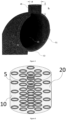
- Figs. 1 shows a capsule 5 having a toroidal shape which is intended for containing a PCM material 15 wherein the PCM have large latent heat of fusion and desirable melting, resp. freezing point that can store, resp. release large amounts of heat.
- Fig. 2 shows a groove pattern on the capsules 5, as visible in greater detail in Fig. 3 , that is remarkable by the incorporation of whole grooves 11, which are continuous and uninterrupted, and additionally partial grooves which are limited 12 in an alternating arrangement 11-12-11-12...11-12-11.... Said grooves 11, resp. 12 are particularly appropriate to increase the surface area of the capsule 5 and hence, heat transfer between the PCM 15 contained in the capsule 5 and the surrounding medium such as a heat transfer fluid 10.
- a set of grooves is thus incorporated on its surface to increase said heat transfer.
- said grooves are arranged on its surface in a radially extending plane. More preferably, said grooves are arranged as whole circular grooves 11 extending as successive uninterrupted circles orthogonally on its longitudinal axis l, circular as well, at a regular distance from each other.
- partial grooves 12 are provided additionally on its surface, also extending radially but as a fraction of circle line also orthogonally on said circular longitudinal axis l at an even distance between two successive adjacent whole circular grooves 11.
- Said fraction of circle line preferably extends over less than half the circle, more preferably at the outer perimeter area of the said toroidal capsules 5, where the distance between adjacent grooves is larger, thereby optimizing the heat transfer increase.
- Said groove pattern thus comprises partial and whole grooves 11, 12, which increases the effective surface and the heat transfer between the stored medium and the surrounding environment.
- the whole grooves 11 which are convolutional
- the partial grooves 12 which are intercalated between successive whole grooves 11 and further improve the heat transfer of the PCM filled capsules 5.
- the number of partial grooves 12 is a function of the ratio of the inner toroidal radius to the outer radius. After a specific ratio between these two, there is a limit of the whole grooves 11 that can be incorporated in the capsule 5.
- Said grooves have the same cross section, which is preferably constant, particularly U-shaped, more particularly square like as shown in Fig. 3 .
- Fig. 3 shows a half fraction of the toroidal capsule 5 with a tubular structure with a circular cross-section, with a cylindric diameter e.g. of 23 mm, further containing the PCM material.
- Said overall radius to diameter ratio is comprised in range between 1,5 and 3,5, preferably 1,7 and 1,9 , more preferably about 1,8 approximately.
- Fig. 9 & 10 show the need to further increase heat transfer at the outer perimeter of the toroidal capsule 5. Since there is a manufacturing limit preventing from placing solely whole grooves 11 on the capsule 5, partial grooves 12 are placed between consecutive whole grooves 11, at the outer perimeter of the capsule's surface. Said partial grooves 12 extend from the outer perimeter section 55 of said capsule 5 inwardly to said geometrical center thereof over a certain distance on said surface of the housing, in particular half or less of the path between said outer and inner perimeters, wherein said outer perimeter section 55 of the toroidal capsule has twice as much grooves, compared to the opposite inner perimeter section 56.
- the toroidal capsules 5 form container devices for PCM material packaged therein.
- the specific toroidal shape selected for the capsule 5 appears to be most appropriate since it allows to store or release heat rapidly, thanks to their larger surface-to-volume ratio, particularly when having a radius of e.g. 41,5 mm corresponding to an external diameter of 83 mm as shown in Fig. 2 . Because of their relatively small size, their manufacturing can be achieved through 3D-printing techniques in abundance and at small cost.
- the capsules are of metal materials, notably including copper, aluminum and stainless steel.
- said capsules are of non-metal materials, notably including polyvinyl chlorides (PVCs), thermoplastics such as low-density polyethylene, polyolefin and high-density polyethylene.
- PVCs polyvinyl chlorides
- thermoplastics such as low-density polyethylene, polyolefin and high-density polyethylene.
- the capsules 5 contain PCM phase change materials 15, which can be organic or inorganic, as well as eutectic materials. Green organic alternatives based on biobased PCMs can also be used.
- the PCM should preferably have a latent heat of fusion in excess of 200 kJ/kg.
- the PCM is filled in the capsule 5 through a socket 45 on the capsule as shown in Fig. 5 .
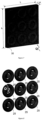
- Fig. 6 shows a thermally insulated thermal energy storage tank 20, including a multitude of toroidal capsules 5, acting as heat collection members.
- a surrounding space 10 is provided within said tank 20 including heat transfer means (air/liquid) to transfer heat from/to the toroidal macro-capsule 5, to/from the PCM material 15 stored in the capsule 5.
- a heat transfer fluid 10 is used that can be either in gas or liquid form.
- the heat transfer fluid can be air, water or any glycol-based mixture such as ethylene-glycol water or propylene glycol water mixtures.
- the process therefor is that the heat transfer fluid 10 is used to drive away the stored heat in the PCM at discharging or store heat at the colder PCM at charging.
- the PCM can therefore be in solid or liquid form.
- the capsules' placement and positioning based on their application are applied: first and foremost, as thermal energy storage represented in Fig. 6 constituents in a thermally insulated tank 20.
- the capsules can also be mainly placed randomly.
- a symmetrical orientation is applicable as shown in Fig. 6 .
- Fig. 7 the passive elements as shown in Fig. 7 , such as building wall envelopes 30 or smaller walls surrounding objects requiring thermal regulation through passive cooling/heating.
- Fig. 8 can be positioned around objects requiring passive heating/cooling as shown in Fig. 8 , such as electrical batteries 25 used in electric transportation.
- the reference packaging capsule 5 represented in fig. 11 has an overall length of e.g. 306 mm, whereas its thickness measured from its cross-section represented in fig. 12 is 43,1 mm. It is thus to be considered that the packaging capsule 5 has rather small dimensions in comparison with the reference corrugated pipe, Fig. 13 , in the known heat exchange device disclosed by this document.
- the global effect thereof is that the performance of the packaging capsules in terms of heat transfer characteristics is improved up to 40 % thanks to the significantly increased heat exchange surface of the extended amount of smaller capsules which are thus mutually added.
- the compact configuration of the packaging capsule according to the invention makes it more sustainable and robust compared to the known corresponding elongated, potentially spiral configuration as shown in fig. 13 .
- the phase change material PCM is stored in a system featured by two holes defining its inlet and outlet respectively, thus defining an open system.
- the encapsulated configuration of the packaging capsule according to the invention which is a closed system that is completely isolated from the surrounding space. It has an orifice yet, which is only used though for the filling of the capsule, and not doing the functioning thereof, when the capsule works.
- the present invention also relates to a process of carrying out a thermal energy storage tank, wherein a heat transfer fluid is introduced to circulate in said system to charge and discharge heat from the overall system to the said thermal energy storage tank and hence the content of the said toroidal capsule contained therein, after a phase change material is encapsulated in the housing through a feeding opening that is formed, wherein the feeding port is communicated with the inside of the packaging capsule and is used for filling the phase change material.
Landscapes
- Engineering & Computer Science (AREA)
- Physics & Mathematics (AREA)
- Thermal Sciences (AREA)
- Mechanical Engineering (AREA)
- General Engineering & Computer Science (AREA)
- Chemical & Material Sciences (AREA)
- Dispersion Chemistry (AREA)
- Packages (AREA)
Claims (19)
- Phasenwechselmaterial-Behältervorrichtung zum Speichern einer Menge eines Speicherungsmaterials, das aus einem Phasenwechselmaterial (phase change material - PCM) besteht, zum Funktionieren als ein Wärmekollektorelement, bestehend aus einer Verpackungskapsel (5), die einen umschließenden Mantel umfasst, der durch ein starres Gehäuse (51) gebildet wird, das eine Außenfläche (52) aufweist und einen befüllbaren Innenraum (54), zum Speichern des Phasenwechselmaterials (PCM) in demselben, umschließt, wobei die Außenfläche des Gehäuses (51) mit einer Wärmetauschervorrichtung (40) versehen ist, wobeidie Kapsel (5) eine kreisringförmige Ringform mit einer Längsachse (ℓ) aufweist unddie Verpackungskapsel (5) mit dem Phasenwechselmaterial (PCM) befüllt, das eine Befüllung (15) bildet, die in derselben verkapselt ist, und aus einem anderen Material als das Gehäuse (51) hergestellt ist, das sowohl chemisch als auch physikalisch von dem PCM-Material, das innerhalb der Kapsel (5) gespeichert wird, verschieden ist, dadurch gekennzeichnet, dass die Wärmetauschervorrichtung (40) aus einem Satz von Rillen (11, 12) besteht, die in der Außenfläche des Gehäuses (51) angeordnet sind,dadurch, dass der Satz von Rillen einen ersten Teilsatz von Rillen (11) umfasst, von denen jede in einer geschlossenen Schleife als eine einzelne Windung angeordnet ist, die sich quer um die Längsachse (ℓ) und durchgehend über den gesamten Querschnittsumfang des kreisringförmigen Gehäuses (51) erstreckt, in einer radialen Ebene, die durch den geometrischen Mittelpunkt (1) der Kapsel (5) hindurchgeht,wobei die Kapsel (5) ein röhrenförmiges Profil mit einem kreisförmigen Querschnitt aufweist, auf dem sich die ersten Rillen (11) als aufeinanderfolgende Kreise senkrecht auf der Längsachse (ℓ), insbes. abstandsgleich beabstandet, erstrecken, unddadurch, dass der Satz von Rillen einen zusätzlichen Teilsatz von Rillen (12) umfasst, der aus unvollständigen Rillen (12) besteht, die jeweils in einer offenen Schleife als nicht-gewundene, begrenzte Rille (12) zwischen aufeinanderfolgenden gewundenen Rillen (11), in einer abwechselnden Anordnung, angeordnet sind, wobei sie sich abstandsgleich an dem äußeren Umfang der Kapsel (5), senkrecht auf der Längsachse (ℓ), über einen Teil eines Kreises erstrecken.
- Behältervorrichtung nach Anspruch 1, dadurch gekennzeichnet, dass die Kapsel (5) ein Verhältnis ihres gesamten Radius zu dem Durchmesser ihres röhrenförmigen Teils aufweist, das in dem Bereich zwischen 1,5 und 3,5, vorzugsweise zwischen 1,7 und 1,9, insbes. annähernd 1,8, eingeschlossen ist, und/oder.
wobei der Radius von dem Mittelpunkt (1) der Kapsel (5) bis zu dem Mittelpunkt ihres röhrenförmigen Querschnitts zwischen 20 und 60 mm eingeschlossen ist und ein Radius des röhrenförmigen Querschnitts zwischen 12 und 18 mm, insbesondere, wobei der Durchmesser der Kapsel (5) < 100 mm, vorzugsweise < 90 mm, insbes. etwa 83 mm, beträgt und der Durchmesser des röhrenförmigen Querschnitts < 30 mm, insbes. etwa 23 mm, beträgt. - Behältervorrichtung nach Anspruch 1 oder 2, dadurch gekennzeichnet, dass sich die unvollständigen Rillen (12) über einen Teil eines Kreises von < ½ Umfang erstrecken, insbes., wobei die Anzahl von Rillen > 60, vorzugsweise > 70 jeweils für jede Kategorie (11, 12) beträgt,
ganz besonders, wobei die Rillen (11, 12) alle wechselseitig denselben Querschnitt, konstant und/oder U-förmig, aufweisen. - Behältervorrichtung nach einem der Ansprüche 1 bis 3, dadurch gekennzeichnet, dass Tüllenmittel (45) auf der Außenfläche des Gehäuses (51) angeordnet sind, die durch eine Öffnung (44) mit dem Innenraum (54) in Verbindung stehen, insbesondere, wobei die Tüllenmittel (45) und die Öffnung (44) auf der Außenfläche des Gehäuses (51) angeordnet sind, und dadurch, dass die Tüllenmittel ein Stutzenmittel (45) zum Befüllen der Kapseln (5) mit dem Speicherungsmaterial PCM (15) umfassen, insbesondere, wobei der Stutzen (45) ein prismatisches Profil entlang einer Achse (l) aufweist, die sich senkrecht von dem kreisringförmigen Gehäuse (51) aus erstreckt, insbes., wobei der Stutzen eine zylindrische Form aufweist, die sich über eine Höhe (h) erstreckt, die zwischen dem Radius (ρ) der Stutzensektion und ihrem Durchmesser (ϕ) eingeschlossen ist, insbesondere, wobei das Verhältnis zwischen der Höhe (h) und dem Radius zwischen 1 und 1,5, vorzugsweise zwischen 1,1 und 1,3, insbes. zwischen 1,15 und 1,2, eingeschlossen ist.
- Behältervorrichtung nach Anspruch 4, dadurch gekennzeichnet, dass der Stutzen (45) aus einem Stück mit dem Gehäuse (51) hergestellt ist, wobei die Kapsel (5) in einem einzigen Stück integriert ist.
- Behältervorrichtung nach einem der Ansprüche 1 bis 5, dadurch gekennzeichnet, dass die Kapsel (5), zumindest zeitweilig, abgedichtet ist, insbes. als eine geschlossene Einheit.
- Behältervorrichtung nach einem der Ansprüche 1 bis 6, dadurch gekennzeichnet, dass die Kapseln (5), insbes. ihr Gehäuse (51), aus Metallwerkstoffen, insbesondere Kupfer, Aluminium und/oder rostfreiem Stahl, hergestellt sind.
- Behältervorrichtung nach einem der Ansprüche 1 bis 7, dadurch gekennzeichnet, dass die PCM-Befüllung (15) aus Materialien mit einer großen latenten Schmelzwärme und einem wünschenswerten Schmelz-/Gefrierpunkt hergestellt ist, die große Wärmemengen speichern/freisetzen, insbes., wobei das PCM eine latente Schmelzwärme von über 200 kJ/kg aufweist.
- Behältervorrichtung nach einem der Ansprüche 1 bis 8, dadurch gekennzeichnet, dass die PCM-Befüllung (15) aus eutektischen Materialien, insbesondere eutektischen Fettsäuregemischen zusammen mit Hydratsalzen, hergestellt ist,
oder dadurch, dass das PCM-Material aus grünen organischen Alternativen auf Grundlage von biobasierten PCM, vor allem essbaren Ölen und Fett, tierischem Abfallfett, Pflanzenölen und Abfallspeiseöl, hergestellt ist. - Behältervorrichtung nach einem der Ansprüche 1 bis 8, dadurch gekennzeichnet, dass die PCM-Befüllung (15) aus organischen Materialien, insbesondere Paraffin und Fettsäuren, oder aus anorganischen Materialien, insbesondere hydratisierten Salzen, hergestellt ist.
- Wärmeenergie-Speicherungssystem zum Wärmemanagement mit kreisringförmiger Makroverkapselung, das eine Vielzahl von Phasenwechselmaterial-Behältervorrichtungen nach einem der vorhergehenden Ansprüche 1 bis 10 umfasst, dadurch gekennzeichnet, dass die Kapseln (5) einzeln und wechselseitig unverbunden enthalten sind, wobei sie eine einzelne Verpackungskapsel (5) bilden, ohne miteinander verbunden zu sein, wobei die kreisringförmigen Kapseln (5) in Verbindung mit einem Wärmeübertragungsfluid (10) arbeiten, das aus einem gasförmigen oder flüssigen Fluid besteht, zum Befördern von Wärme zwischen unterschiedlichen Punkten innerhalb des gesamten Systems, in dem sie enthalten sind, insbesondere, wobei das System angeordnet ist, um Wärmeenergie bei Temperaturen, höher als - 10 °C und niedriger als 80 °C, zu speichern und abzugeben.
- Wärmeenergie-Speicherungssystem mit kreisringförmiger Makroverkapselung, das in Verbindung mit einer Vielzahl von den kreisringförmigen PCM-befüllten Kapseln (5), die als Wärmesammlungselemente funktionieren, arbeitet, nach dem vorhergehenden Anspruch 11, dadurch gekennzeichnet, dass die Temperatur in einem Arbeitsbereich > - 10 °C und < + 4 °C und/oder zwischen + 10 °C und + 30 °C eingeschlossen ist.
- Wärmeenergie-Speicherungssystem nach Anspruch 11 oder 12, dadurch gekennzeichnet, dass es eine wärmeisolierte Umhüllung, einen Energiespeicherungstank (20), der eine Vielzahl von Kapseln (5), insbes. praktisch identischen, einschließt, wobei der Wärmeaustausch durch das Wärmeübertragungsfluid (10) ausgeführt wird, das in den Tank (20) eingeleitet wird, um alle von der Vielzahl von Kapseln (5), welche die Wärmeregulierung erfordern, darin zu umschließen, um in dem Tank (20) im Umlauf zu sein, um Wärme von dem gesamten System zu laden und abzugeben an den Wärmeenergie-Speicherungstank (10) und folglich den Inhalt der Kapseln (5), die darin enthalten sind,
insbesondere, wobei das Wärmeübertragungsfluid (10) ausschließlich Wasser oder ein 50:50-Wasser-Glykol-Gemisch nach Gewicht ist, das in dem Tank (20) und folglich den PCM-befüllten Kapseln (5) in Umlauf ist, wobei es entweder die erzeugten Wärmelasten der warmen Speicherung wegleitet oder die Wärmelasten in dem gekühlten Speicherungstank speichert, ganz besonders, wobei die PCM-befüllten Kapseln (5) symmetrisch innerhalb des Tanks (20) angeordnet sind. - Wärmeenergie-Speicherungssystem nach einem der Ansprüche 11 bis 13, dadurch gekennzeichnet, dass die Kapsel (5) zumindest zeitweilig abgedichtet ist, um das verkapselte PCM zu enthalten, insbesondere, wobei die Positionierung der kreisringförmigen Kapseln in einer Festbett-Konfiguration bereitgestellt wird, die aus einer großen Anzahl von kreisringförmigen Kapseln besteht, die einzeln angeordnet sind.
- Wärmeenergie-Speicherungssystem nach Anspruch 11 oder 12, dadurch gekennzeichnet, dass die Kapseln (5') in passiven Elementen, insbesondere Gebäudehüllen (30) oder kleineren Wänden, eingebettet sind, die Objekte zur Wärmeregulierung durch passive Kühlung und Heizung umschließen, wobei die Kapseln als ein passives Element angeordnet sind, das aus der Gebäudewandhülle besteht, wobei die PCM-befüllten Kapseln (5') innerhalb der Gebäudewände als passive Elemente angeordnet sind, um einen Gebäudeenergieverbrauch zu verringen und eine Innenraumumgebung zu verbessern, wobei die Wände, welche die kreisringförmigen Kapseln (5') einschließen, entsprechend dem Betrieb als die Wärmesenken/-quellen funktionieren,
insbesondere, wobei, wenn die Temperatur des Raums, der innerhalb der Hüllenwände eingeschlossen ist, die Phasenwechseltemperatur überschreitet, die kreisringförmigen PCM-befüllten Kapseln (5') als Wärmesenken funktionieren, wobei sie die zusätzliche Wärme des Raums absorbieren, wobei sie die Temperatur auf spezifischen Temperaturniveaus aufrechterhalten, beziehungsweise, wobei, wenn die Temperatur des eingeschlossenen Raums unter ein bestimmtes Temperaturniveau herabgesetzt wird, die kreisringförmigen Kapseln, die PCM-Material umfassen, die Wärme freisetzen und die Temperatur des Raums konstant aufrechterhalten, insbesondere, wobei das Wärmeübertragungsfluid Luft ist, die entweder auf eine natürliche Weise genutzt wird - was dann einer schwerkraftbasierten Konvektion entspricht, ganz besonders, wobei ein sekundäres Lüftungssystem enthalten ist, durch welches das Wärmeübertragungsfluid (10) dann in einer Zwangskonvektion verwendet wird. - Wärmeenergie-Speicherungssystem nach Anspruch 11 oder 12, dadurch gekennzeichnet, dass die Positionierung der kreisringförmigen Kapseln (5") auf eine ausgerichtete Weise um zylindrische Objekte, insbesondere Batterien zu hybrid-elektrischen Beförderung, bereitgestellt wird,
wobei es auf einem passiven Kühlungs-/Heizungsvorgang beruht, wobei die kreisringförmige Kapsel Teil eines Kühlungs-/Heizungssystems eines Objekts, insbesondere einer elektrischen Batterie, ist, wobei die durch das Objekt erzeugte/absorbierte Wärme durch das PCM-Material absorbiert/bereitgestellt wird, um die Temperatur des Objekts innerhalb seiner Betriebstemperaturgrenzen aufrechtzuerhalten, wobei dies die Nutzungsdauer der gekühlten/geheizten Objekte steigert, die Gesamtkosten des Systems, wo die Objekte platziert sind, verringert, wobei das Wärmeübertragungsfluid aus der Umgebungsluft besteht, ganz besonders, wobei ein zweites Kühlungssystem auf Grundlage eines flüssigen Kühlmittels verwendet wird, um die Wärmelasten des Objekts, wie beispielsweise der Batterie, wegzuleiten. - Verwendung eines Wärmeenergie-Speicherungssystems nach einem der Ansprüche 11 bis 16 durch Bereitstellen einer aktiven oder passiven Kühlung für Systeme, wie beispielsweise Energieerzeugung, Gebäudehüllen, und um Objekte, die eine Wärmeregulierung in einem spezifischen Betriebstemperaturbereich erfordern, insbesondere elektrische Batterien zur hybrid-elektrischen Beförderung.
- Verfahren zum Herstellen einer Phasenwechselmaterial-Behältervorrichtung nach einem der Ansprüche 1 bis 10 zur Verwendung in einem Wärmeenergie-Speicherungssystem nach einem der Ansprüche 11 bis 16, dadurch gekennzeichnet, dass die Kapseln durch 3D-Drucken erzeugt werden, um eine große Menge derselben hervorzubringen.
- Verfahren zum Betreiben eines Wärmeenergie-Speicherungssystems nach einem der Ansprüche 13 bis 17, dadurch gekennzeichnet, dass ein Wärmeübertragungsfluid (10) in dem System eingeleitet wird, um in dem System in Umlauf zu sein, um Wärme von dem gesamten System zu laden und abzugeben an den Wärmeenergie-Speicherungstank (20) und folglich den Inhalt der kreisringförmigen Kapsel (5), die darin enthalten ist, nachdem ein Phasenwechselmaterial (PCM) in dem Gehäuse (52) der kreisringförmigen Kapsel (5) verkapselt ist, durch eine Einspeisungsöffnung, die geformt ist, wobei der Einspeisungsanschluss mit der Innenseite der Verpackungskapsel (5) in Verbindung steht und zum Einfüllen des Phasenwechselmaterials (PCM) verwendet wird, insbesondere, wobei die Kapsel auf eine dauerhafte oder zeitweilige Weise mit dem PCM-Material befüllt wird, nachdem es durch einen Stutzen darin eingeschlossen wird.
Applications Claiming Priority (1)
| Application Number | Priority Date | Filing Date | Title |
|---|---|---|---|
| GR20220100448A GR1010488B (el) | 2022-05-30 | 2022-05-30 | Δοχειο ενθυλακωσης για συστημα αποθηκευσης θερμικης ενεργειας με μακροενθυλακωση |
Publications (3)
| Publication Number | Publication Date |
|---|---|
| EP4286783A1 EP4286783A1 (de) | 2023-12-06 |
| EP4286783C0 EP4286783C0 (de) | 2025-04-09 |
| EP4286783B1 true EP4286783B1 (de) | 2025-04-09 |
Family
ID=86609868
Family Applications (1)
| Application Number | Title | Priority Date | Filing Date |
|---|---|---|---|
| EP23175989.5A Active EP4286783B1 (de) | 2022-05-30 | 2023-05-30 | Kapselverpackungsvorrichtung für ein wärmeenergiespeichersystem mit makroverkapselung |
Country Status (2)
| Country | Link |
|---|---|
| EP (1) | EP4286783B1 (de) |
| GR (1) | GR1010488B (de) |
Family Cites Families (11)
| Publication number | Priority date | Publication date | Assignee | Title |
|---|---|---|---|---|
| US2525261A (en) * | 1946-09-30 | 1950-10-10 | James P Henderson | Refrigerated ball dispenser |
| US4205656A (en) * | 1978-06-06 | 1980-06-03 | Scarlata Robert W | Thermal storage reservoirs |
| AU1334395A (en) * | 1993-12-10 | 1995-06-27 | Store Heat And Produce Energy, Inc. | Thermal storage apparatus |
| JPH0921592A (ja) * | 1995-07-04 | 1997-01-21 | Fuji Electric Co Ltd | 潜熱蓄熱カプセル |
| JP2009520374A (ja) | 2005-12-20 | 2009-05-21 | コーニンクレッカ フィリップス エレクトロニクス エヌ ヴィ | 縦型相変化メモリセルおよびその製造方法 |
| US20120018116A1 (en) * | 2010-07-21 | 2012-01-26 | Terrafore, Inc | Thermal energy storage system comprising encapsulated phase change material |
| JP6248623B2 (ja) * | 2013-02-18 | 2017-12-20 | 株式会社リコー | 反応材及びケミカルヒートポンプ |
| CN104634152A (zh) * | 2015-02-11 | 2015-05-20 | 李渊 | 一种蓄能设备 |
| EP4290169A3 (de) * | 2017-09-25 | 2024-02-28 | Nostromo Ltd. | Wärmeenergiespeicheranordnung |
| JP7477180B2 (ja) * | 2018-09-25 | 2024-05-01 | ノストローモ リミテッド | 蓄熱容器内の流体の流れ |
| CN210374746U (zh) | 2019-05-30 | 2020-04-21 | 深圳市爱能森科技有限公司 | 一种相变材料封装结构及储热罐 |
-
2022
- 2022-05-30 GR GR20220100448A patent/GR1010488B/el active IP Right Grant
-
2023
- 2023-05-30 EP EP23175989.5A patent/EP4286783B1/de active Active
Also Published As
| Publication number | Publication date |
|---|---|
| GR1010488B (el) | 2023-06-16 |
| EP4286783C0 (de) | 2025-04-09 |
| EP4286783A1 (de) | 2023-12-06 |
Similar Documents
| Publication | Publication Date | Title |
|---|---|---|
| US9865907B2 (en) | Cooling mechanism for batteries using L-V phase change materials | |
| EP3523840B1 (de) | Batteriekasten für automobilbatterie-temperatur-management | |
| EP0330312A2 (de) | Verfahren und Vorrichtung zur thermischen Speicherung | |
| EP1979697B1 (de) | Wärmeenergiespeichervorrichtung | |
| US4355627A (en) | Thermal storage system | |
| US11764422B2 (en) | Thermal management of energy storage devices via oscillating heat pipes | |
| CN101932898A (zh) | 改进的潜热储存设备 | |
| EP2942591B1 (de) | Wärmeenergie-speichersystem mit einem wärmeempfindlichen feststoffmaterial und einem phasenwechselmaterial | |
| KR20120139704A (ko) | 열 에너지 저장 | |
| KR20120104182A (ko) | 수소 및/또는 열을 저장하고 방출하는 탱크 | |
| US20190003781A1 (en) | A thermal storage system and temperature controlled container comprising the same | |
| US20130105106A1 (en) | Systems And Methods For Thermal Energy Storage | |
| US20100051227A1 (en) | Thermal energy storage | |
| KR102228996B1 (ko) | 상변화물질을 이용한 이중관 열교환기 | |
| GB2532485A (en) | An apparatus for storage of sensible heat | |
| EP4286783B1 (de) | Kapselverpackungsvorrichtung für ein wärmeenergiespeichersystem mit makroverkapselung | |
| Ismail et al. | Numerical investigation of fin geometries on the effectiveness of passive, phase-change material− based thermal management systems for lithium-ion batteries | |
| EP2976588B1 (de) | Isolierter speichertank für geschmolzene salze | |
| CN216120476U (zh) | 一种具有相变蓄热液冷式电池组散热装置 | |
| JP3873229B2 (ja) | 温蓄熱装置 | |
| CN114935273B (zh) | 一种多级相变球蓄热装置 | |
| EP4294655B1 (de) | Hybrider speicher mit mehreren quellen | |
| CN222783983U (zh) | 相变蓄热器 | |
| KR200246702Y1 (ko) | 수소저장합금 수소저장탱크 | |
| EP3976500B1 (de) | Wärmerohrgekühlter palettenverlader |
Legal Events
| Date | Code | Title | Description |
|---|---|---|---|
| PUAI | Public reference made under article 153(3) epc to a published international application that has entered the european phase |
Free format text: ORIGINAL CODE: 0009012 |
|
| STAA | Information on the status of an ep patent application or granted ep patent |
Free format text: STATUS: THE APPLICATION HAS BEEN PUBLISHED |
|
| AK | Designated contracting states |
Kind code of ref document: A1 Designated state(s): AL AT BE BG CH CY CZ DE DK EE ES FI FR GB GR HR HU IE IS IT LI LT LU LV MC ME MK MT NL NO PL PT RO RS SE SI SK SM TR |
|
| STAA | Information on the status of an ep patent application or granted ep patent |
Free format text: STATUS: REQUEST FOR EXAMINATION WAS MADE |
|
| 17P | Request for examination filed |
Effective date: 20240527 |
|
| RBV | Designated contracting states (corrected) |
Designated state(s): AL AT BE BG CH CY CZ DE DK EE ES FI FR GB GR HR HU IE IS IT LI LT LU LV MC ME MK MT NL NO PL PT RO RS SE SI SK SM TR |
|
| GRAP | Despatch of communication of intention to grant a patent |
Free format text: ORIGINAL CODE: EPIDOSNIGR1 |
|
| STAA | Information on the status of an ep patent application or granted ep patent |
Free format text: STATUS: GRANT OF PATENT IS INTENDED |
|
| INTG | Intention to grant announced |
Effective date: 20241126 |
|
| GRAS | Grant fee paid |
Free format text: ORIGINAL CODE: EPIDOSNIGR3 |
|
| GRAA | (expected) grant |
Free format text: ORIGINAL CODE: 0009210 |
|
| STAA | Information on the status of an ep patent application or granted ep patent |
Free format text: STATUS: THE PATENT HAS BEEN GRANTED |
|
| AK | Designated contracting states |
Kind code of ref document: B1 Designated state(s): AL AT BE BG CH CY CZ DE DK EE ES FI FR GB GR HR HU IE IS IT LI LT LU LV MC ME MK MT NL NO PL PT RO RS SE SI SK SM TR |
|
| REG | Reference to a national code |
Ref country code: GB Ref legal event code: FG4D |
|
| REG | Reference to a national code |
Ref country code: CH Ref legal event code: EP |
|
| REG | Reference to a national code |
Ref country code: DE Ref legal event code: R096 Ref document number: 602023002798 Country of ref document: DE |
|
| REG | Reference to a national code |
Ref country code: IE Ref legal event code: FG4D |
|
| U01 | Request for unitary effect filed |
Effective date: 20250410 |
|
| U07 | Unitary effect registered |
Designated state(s): AT BE BG DE DK EE FI FR IT LT LU LV MT NL PT RO SE SI Effective date: 20250416 |
|
| PGFP | Annual fee paid to national office [announced via postgrant information from national office to epo] |
Ref country code: GR Payment date: 20250526 Year of fee payment: 3 |
|
| REG | Reference to a national code |
Ref country code: GR Ref legal event code: EP Ref document number: 20250400916 Country of ref document: GR Effective date: 20250613 |
|
| PG25 | Lapsed in a contracting state [announced via postgrant information from national office to epo] |
Ref country code: ES Free format text: LAPSE BECAUSE OF FAILURE TO SUBMIT A TRANSLATION OF THE DESCRIPTION OR TO PAY THE FEE WITHIN THE PRESCRIBED TIME-LIMIT Effective date: 20250409 |
|
| PG25 | Lapsed in a contracting state [announced via postgrant information from national office to epo] |
Ref country code: NO Free format text: LAPSE BECAUSE OF FAILURE TO SUBMIT A TRANSLATION OF THE DESCRIPTION OR TO PAY THE FEE WITHIN THE PRESCRIBED TIME-LIMIT Effective date: 20250709 |
|
| PG25 | Lapsed in a contracting state [announced via postgrant information from national office to epo] |
Ref country code: PL Free format text: LAPSE BECAUSE OF FAILURE TO SUBMIT A TRANSLATION OF THE DESCRIPTION OR TO PAY THE FEE WITHIN THE PRESCRIBED TIME-LIMIT Effective date: 20250409 |
|
| PG25 | Lapsed in a contracting state [announced via postgrant information from national office to epo] |
Ref country code: HR Free format text: LAPSE BECAUSE OF FAILURE TO SUBMIT A TRANSLATION OF THE DESCRIPTION OR TO PAY THE FEE WITHIN THE PRESCRIBED TIME-LIMIT Effective date: 20250409 |
|
| PG25 | Lapsed in a contracting state [announced via postgrant information from national office to epo] |
Ref country code: RS Free format text: LAPSE BECAUSE OF FAILURE TO SUBMIT A TRANSLATION OF THE DESCRIPTION OR TO PAY THE FEE WITHIN THE PRESCRIBED TIME-LIMIT Effective date: 20250709 |
|
| PG25 | Lapsed in a contracting state [announced via postgrant information from national office to epo] |
Ref country code: IS Free format text: LAPSE BECAUSE OF FAILURE TO SUBMIT A TRANSLATION OF THE DESCRIPTION OR TO PAY THE FEE WITHIN THE PRESCRIBED TIME-LIMIT Effective date: 20250809 |
|
| U21 | Renewal fee for the european patent with unitary effect paid with additional fee |
Year of fee payment: 3 Effective date: 20251117 |
|
| PG25 | Lapsed in a contracting state [announced via postgrant information from national office to epo] |
Ref country code: SM Free format text: LAPSE BECAUSE OF FAILURE TO SUBMIT A TRANSLATION OF THE DESCRIPTION OR TO PAY THE FEE WITHIN THE PRESCRIBED TIME-LIMIT Effective date: 20250409 |
|
| PG25 | Lapsed in a contracting state [announced via postgrant information from national office to epo] |
Ref country code: CZ Free format text: LAPSE BECAUSE OF FAILURE TO SUBMIT A TRANSLATION OF THE DESCRIPTION OR TO PAY THE FEE WITHIN THE PRESCRIBED TIME-LIMIT Effective date: 20250409 |
|
| PGFP | Annual fee paid to national office [announced via postgrant information from national office to epo] |
Ref country code: IE Payment date: 20251128 Year of fee payment: 3 |
|
| PG25 | Lapsed in a contracting state [announced via postgrant information from national office to epo] |
Ref country code: SK Free format text: LAPSE BECAUSE OF FAILURE TO SUBMIT A TRANSLATION OF THE DESCRIPTION OR TO PAY THE FEE WITHIN THE PRESCRIBED TIME-LIMIT Effective date: 20250409 |
|
| PG25 | Lapsed in a contracting state [announced via postgrant information from national office to epo] |
Ref country code: MC Free format text: LAPSE BECAUSE OF FAILURE TO SUBMIT A TRANSLATION OF THE DESCRIPTION OR TO PAY THE FEE WITHIN THE PRESCRIBED TIME-LIMIT Effective date: 20250409 |
|
| PLBE | No opposition filed within time limit |
Free format text: ORIGINAL CODE: 0009261 |
|
| STAA | Information on the status of an ep patent application or granted ep patent |
Free format text: STATUS: NO OPPOSITION FILED WITHIN TIME LIMIT |
|
| REG | Reference to a national code |
Ref country code: CH Ref legal event code: L10 Free format text: ST27 STATUS EVENT CODE: U-0-0-L10-L00 (AS PROVIDED BY THE NATIONAL OFFICE) Effective date: 20260218 |
|
| 26N | No opposition filed |
Effective date: 20260112 |