EP4286750A1 - Extraction device, combination appliance and method for operating an extraction device or a combination appliance - Google Patents
Extraction device, combination appliance and method for operating an extraction device or a combination appliance Download PDFInfo
- Publication number
- EP4286750A1 EP4286750A1 EP22176878.1A EP22176878A EP4286750A1 EP 4286750 A1 EP4286750 A1 EP 4286750A1 EP 22176878 A EP22176878 A EP 22176878A EP 4286750 A1 EP4286750 A1 EP 4286750A1
- Authority
- EP
- European Patent Office
- Prior art keywords
- air
- extraction device
- operating mode
- filter
- exhaust opening
- Prior art date
- Legal status (The legal status is an assumption and is not a legal conclusion. Google has not performed a legal analysis and makes no representation as to the accuracy of the status listed.)
- Pending
Links
- 238000000605 extraction Methods 0.000 title claims abstract description 106
- 238000000034 method Methods 0.000 title claims abstract description 30
- 238000010411 cooking Methods 0.000 claims description 78
- 239000003517 fume Substances 0.000 claims description 17
- 238000004887 air purification Methods 0.000 claims description 15
- 230000004913 activation Effects 0.000 claims description 12
- 239000004519 grease Substances 0.000 claims description 6
- 238000011144 upstream manufacturing Methods 0.000 claims description 6
- 239000012530 fluid Substances 0.000 claims description 5
- 239000002241 glass-ceramic Substances 0.000 claims description 4
- 239000000428 dust Substances 0.000 claims description 3
- 230000001960 triggered effect Effects 0.000 claims description 3
- 239000003570 air Substances 0.000 description 145
- 239000012855 volatile organic compound Substances 0.000 description 6
- 239000003610 charcoal Substances 0.000 description 4
- 239000002245 particle Substances 0.000 description 4
- 230000000694 effects Effects 0.000 description 3
- 238000010586 diagram Methods 0.000 description 2
- 230000006698 induction Effects 0.000 description 2
- 230000000977 initiatory effect Effects 0.000 description 2
- 238000009434 installation Methods 0.000 description 2
- 238000012423 maintenance Methods 0.000 description 2
- 238000005259 measurement Methods 0.000 description 2
- 238000012986 modification Methods 0.000 description 2
- 230000004048 modification Effects 0.000 description 2
- 238000000746 purification Methods 0.000 description 2
- 238000004378 air conditioning Methods 0.000 description 1
- 239000012080 ambient air Substances 0.000 description 1
- 238000005452 bending Methods 0.000 description 1
- 238000007664 blowing Methods 0.000 description 1
- 230000003111 delayed effect Effects 0.000 description 1
- 238000013461 design Methods 0.000 description 1
- 230000002349 favourable effect Effects 0.000 description 1
- 238000001914 filtration Methods 0.000 description 1
- 238000000926 separation method Methods 0.000 description 1
- 230000008054 signal transmission Effects 0.000 description 1
- 230000000391 smoking effect Effects 0.000 description 1
- 239000000126 substance Substances 0.000 description 1
Images




Classifications
-
- F—MECHANICAL ENGINEERING; LIGHTING; HEATING; WEAPONS; BLASTING
- F24—HEATING; RANGES; VENTILATING
- F24C—DOMESTIC STOVES OR RANGES ; DETAILS OF DOMESTIC STOVES OR RANGES, OF GENERAL APPLICATION
- F24C15/00—Details
- F24C15/20—Removing cooking fumes
- F24C15/2042—Devices for removing cooking fumes structurally associated with a cooking range e.g. downdraft
Definitions
- the present invention relates to an extraction device comprising an air channel system, an air transportation means and a filter unit according to the preamble of claim 1.
- the present invention also relates to a combination appliance comprising a cooking hob and an extraction device according to the preamble of claim 13.
- the present invention further relates to a method for operating an extraction device or a combination appliance according to the preamble of claim 14.
- an extraction device particularly an extractor hood
- Said extraction device is operated in parallel to the cooking hob, thereby sucking in those cooking vapours in order to filter out particles and tiny droplets from the vapours and/or to blow the vapours to the outside of the building.
- Such an extractor hood may be arranged above the cooking area or it may be included in a combination appliance, which is a configuration of an entity including the extractor hood and the cooking hob.
- Such kind of extraction device is usually arranged as an extraction unit below a worktop of the related cooking hob and it comprises at least one fan for sucking air from the cooking area through an opening arranged in the worktop, which air flows through an air channel system, in which a filter unit is arranged for a removal of cooking fumes, to an exhaust outlet.
- Respective devices are known for air conditioning and air purification, which devices are equipped with different types of fluids or air filters providing a removal of pollution from the indoor air.
- CN109323311A discloses an integrated stove, which is capable of performing an extraction of cooking vapours according to a first functionality and of performing an air purification according to a second functionality.
- a common inlet opening is provided and, after passing a common filter unit, the conveyed air is forwarded to a smoking box and, consecutively, to an air duct system.
- the air duct system splits up into a main end pipe for an outdoor exhausting of cooking fumes and an auxiliary end pipe for a recirculation of purified room air.
- a switching assembly is included for selectively opening and closing passages to the main and auxiliary pipes.
- An extraction device comprises an air channel system for air conveyance with at least one suction opening and at least one exhaust opening, an air transportation means, in particular an air blower, and a filter unit comprising at least one first filter element.
- the extraction device is configured to be operated in a first operating mode and in a second operating mode.
- the air channel system comprises a branch or junction.
- the air channel system further comprises at least one shut-off means, which provides access to at least a second air conduit, when the extraction device is operated in the second operating mode.
- the shut-off means is in particular at least one shut-off valve, preferably an electrical shut-off valve.
- the air channel system further comprises a changeover means with a first outlet and a second outlet for guiding at least a portion of the conveyed air either through the first outlet to a first air conduit or to the at least one exhaust opening, or through the second outlet to a second air conduit.
- Said conveyed air or conveyed air portion is guided to the first air conduit or to the at least one exhaust opening, when the extraction device is operated in the first operating mode.
- the at least a portion of the conveyed air is guided to the second air conduit, when the extraction device is operated in the second operating mode.
- the branch or junction and the changeover means are arranged at a first end of the first air conduit and at a first end of the second air conduit.
- the branch or junction and the changeover means or the shut-off means are arranged downstream of the air transportation means.
- at least one air treatment means is arranged in the second air conduit.
- the at least one air treatment means impinges on the air guided through the second air conduit.
- Said changeover means may be a changeover valve, preferably an electrical changeover valve. With such air treatment means the air may be treated in a particular manner, especially in addition to the filtering effect performed by the filter unit comprising the at least one first filter element.
- a preferred embodiment of the present invention is characterized in that the filter unit, which comprises the at least one first filter element, is a first filter device, and in that the air treatment means is or comprises a second filter device, which particularly comprises a second filter element.
- the first operating mode may be a cooking fumes extraction mode, in which the air transportation means aspirates air comprising cooking fumes from an area above a cooking zone.
- the second operating mode may be an air purifying mode, in which the air transportation means aspirates air from a space, in which the extraction device is arranged.
- the at least one air treatment means which is particularly the second filter device, comprises an air purifying filter means.
- the air purifying filter means preferably includes an odour and/or a dust filter unit, especially a VOC or TVOC filter unit eliminating any kind of volatile organic compounds. More specifically, the air purifying means particularly comprises at least one of a HEPA filter, a PECO filter, an Ulpa filter, and a fluid filter means.
- the extraction device favourably comprises a common suction opening, which is provided for the operation of the extraction device both in the first operating mode and in the second operating mode.
- the common suction opening is preferably arranged or arrangeable on a cooktop of a cooking hob, which is assigned to the extraction device.
- the common suction opening is arranged or arrangeable in a centre zone of the cooktop, which particularly is a glass ceramic cooktop.
- a first exhaust opening is arranged at a second end of the first air conduit, and a second exhaust opening is arranged at a second end of the second air conduit.
- the second exhaust opening is arranged or arrangeable on a cooktop, particularly a glass ceramic cooktop, of a cooking hob, which cooking hob is assigned to the extraction device.
- the second exhaust opening is arranged or arrangeable on a worktop of a kitchen cabinet, in which the extraction device is mounted or mountable.
- the second exhaust opening may be arranged in a bottom area of a cabinet, in which the extraction device may be arranged or arrangeable.
- first exhaust opening that includes at least a first first exhaust opening and a second first exhaust opening, which first first and second first exhaust openings are spaced from one another and/or which are spaced from the suction opening.
- first and second exhaust openings that are arranged that way, i. e. spaced from one another and/or spaced from the suction opening.
- at least one of the first and second exhaust openings may comprise orientable air guiding means, e. g. flaps, in order to avoid short-circuit air recirculation causing exhaust air to be directly aspirated through the suction opening.
- the filter unit which comprises the at least one first filter element, may be arranged downstream, in particular directly downstream, of the suction opening and/or it may be accessible through the suction opening.
- Said filter unit is particularly the first filter device, which preferably comprises a grease filter element and/or an odour filter element.
- the at least one air treatment means may be arranged upstream, in particular directly upstream, of the exhaust opening, which is particularly the second exhaust opening, and/or it may be accessible through the exhaust opening. More specifically, the exhaust opening is the second exhaust opening.
- the at least one air treatment means may comprise the second filter device and/or the second filter element.
- the first operating mode which is particularly the cooking fumes extraction mode, is a recirculation mode, i. e. the air is conveyed in a recirculated flow.
- a recirculation mode i. e. the air is conveyed in a recirculated flow.
- the at least one suction opening and the at least one exhaust opening are arranged in the same room or space, in particular a kitchen room.
- said first operating mode is an exterior release mode. According to that, provisions may be made that the at least one suction opening and the at least one exhaust opening are arranged in different rooms or spaces.
- the at least one exhaust opening, in particular the first exhaust opening is preferably arranged outside of the building.
- the second operating mode which is particularly said air purifying mode, is preferably a recirculation mode.
- the at least one suction opening and the at least one exhaust opening, in particular the second exhaust opening are arranged in the same room or space.
- Such recirculation especially in a nearly enclosed space, may provide for a gradually purified room atmosphere.
- both the first air conduit and the second air conduit merge into a common exhaust opening. That way, only one opening outlet has to be provided, which may also reduce the effort for the installation of the extraction device in a kitchenette.
- both the first air conduit and the second air conduit may merge into a common air channel end section. Accordingly, the common air channel end section may open into said common exhaust opening for an air outlet.
- an air conduit closing means is included configured for closing at least a second end of the second air conduit, when the extraction device is operated or operable in the first operating mode, which may be the cooking fumes extraction mode.
- the second end of the second air conduit is arranged downstream of the air treatment means.
- said air closing means is particularly a second changeover valve having a first inlet and a second inlet. With said air closing means any return flow of air into the second air conduit via its second end may be preventable, and the second air conduit may be closed off from its both ends.
- the second operating mode in particular the air purifying mode, may be an operating mode, in which the air transportation means is operated with low power and/or with low conveying capacity. This may increase the purification effect, what means that the respective air treatment means may operate in an optimized way, when the air throughput is reduced.
- the second operating mode is performed at the end of a cooking process or on a user's specific selection.
- a combination appliance which comprises a cooking hob for performing cooking processes and an extraction device according to anyone of the herein disclosed embodiments.
- the combination appliance is configured to be electively operated in a first operating mode, which may be a cooking fumes extraction mode, or in a second operating mode, which may be an air purifying mode.
- the operation of the combination appliance, and particularly of the included extraction device is preferably performed based on a user's selection and/or by automated activation by means of a software application.
- Said software application may include a routine of receiving an input of a timer and/or of a sensor signal, and the operation of the extraction device is particularly triggered by said timer and/or sensor signal.
- a method for operating an extraction device or a combination appliance is operable by a first operating mode, in which cooking fumes are removed from a cooking zone or area, and by a second operating mode, in which air is aspirated from a space, where the extraction device or the combination appliance is arranged.
- the second operating mode is provided for an air purification, in particular of ambient air, more specifically of the air in the room, e. g. a kitchen, forming the installation location of the extraction device or the combination appliance.
- the method is determined by air being sucked in through at least one suction opening and being conveyed in an air channel system from the at least one suction opening to at least one exhaust opening of the air channel.
- shut-off means at least to a second air conduit, when the extraction device is operated in the second operating mode.
- a changeover means may be implemented.
- said at least a portion of the conveyed air may be guided at the branch or junction to a first air conduit or to a second conduit.
- said changeover means comprises a first outlet and a second outlet, and the changeover means causes the air either to take the way to a first air conduit or to at least one of the at least one exhaust opening via the first outlet, or to take the way to a second air conduit via the second outlet.
- the first outlet is accessible to the airflow, when the extraction device is operated in the first operating mode, and the second outlet is accessible, when the extraction device is operated in the second operating mode.
- Each one of the first air conduit and the second air conduit opens into at least one of the at least one exhaust opening, which may mean either that the first and second air conduit open into a common space or chamber that forms or is arranged upstream of a common exhaust opening, or that at least one first exhaust opening allocated to the first air conduit and at least one second exhaust outlet allocated to the second air conduit are provided.
- at least one air treatment means impinges on the air for the purpose of air purification, when the extraction device or the combination appliance is operated in the second operating mode. During said second operating mode the air is particularly guided through the second air conduit.
- said air treatment means may be an air purifying filter means, which preferably includes an odour and/or a dust filter unit, especially a VOC or TVOC filter unit eliminating any kind of volatile organic compounds. More specifically, the air purifying means particularly comprises at least an air treatment filter, particularly at least a HEPA filter, a PECO filter, an Ulpa filter, and/or a fluid filter means.
- shut-off means preferably being a shut-off valve
- the shut-off means is switched between an open state and a closed state by means of an electrical control signal.
- a changeover means is implemented instead of a shut-off means, which changeover means is preferably a changeover valve, it is switched from the first outlet to the second outlet or vice versa, i. e. from the second outlet to the first outlet, by means of an electrical control signal.
- the control signal is based on a user's manual activation or on an automatic activation. In case of the manual activation, the user selects at least one of the first operating mode or the second operating mode.
- Said manual activation is particularly performed on a control device of the extraction device or the combination appliance or on an input means of a smart device, such as a smart phone or a tablet computer.
- a smart device such as a smart phone or a tablet computer.
- a wireless connection is used for signal transmission.
- a specific algorithm implemented in a software application may be provided for controlling the selection of at least one of the first and second operating modes. The selection may be based on a timer signal and/or on a sensor signal, which sensor signal detects at least one status value of the conveyed air.
- the status value is particularly at least one of a humidity value, a temperature value and/or a VOC value.
- the method may be established such that a user can selectively chose either the first operating mode or the second operating mode, i. e. the changeover means may be switched to either the first outlet or to the second outlet.
- the changeover means may be switched to either the first outlet or to the second outlet.
- a related power level and/or air flow quantity may be selectable by a respective user input.
- the operation may be immediately started or means for a delayed start may be provided.
- the method may be established that a software application can selectively trigger either the first operating mode or the second operating mode.
- the operation of the extraction device may be triggered by a specific hob control signal, e. g. based on a selected power level of an operated cooking zone or based on a specific cooking program selected by the user.
- a timer and/or a sensor signal may not only trigger the second operating mode to be selected, but also any parameters for the operation of the extraction device may be chosen and/or set.
- the method described herein, particularly the air functionalities, may be operated and/or controlled on a remote basis, especially by means of a software application, wherein any known connectivity means, e. g. mobile and/or wireless connectivity solutions, may be used.
- any known connectivity means e. g. mobile and/or wireless connectivity solutions
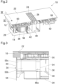
- Fig. 1 illustrates a combination appliance 10 comprising a cooking hob 12 and a downdraft extraction device 14 installed in a kitchen cabinet 16.
- the cooking hob 12 is installed in a cut-out of a kitchen countertop 18 forming a top cover plate of the kitchen cabinet 16.
- the downdraft extraction device 14 is configured to take away cooking vapours generated during cooking processes, in particular when cooking with uncovered cookware.
- the cooking hob 12 comprises cooking regions 20a, 20b arranged on a left half and a right half of a worktop 22 of the cooking hob 12, which left and right halves are separated from each other by a suction opening 24 for an intake of the cooking vapours, the suction opening 24 being arranged alongside a worktop centreline.
- the suction opening 24 is covered by a cover grid 26 for preventing items, e. g. cookware, to fall into the suction opening 24.
- a casing 28 of the extraction device 14 is shown in Fig. 1 in transparent illustration.
- Said casing 28 provides a closed outer shell or first channel section for a flow of the sucked-in air including the cooking vapours on their way from the suction opening 24 to an exhaust opening 30 in a base area 32 of the kitchen cabinet 16.
- Said exhaust opening 30 is also covered, specifically by an outlet grille 34.
- the flow of the sucked-in air through the extraction device 14 is driven by the operation of an extraction fan 36 arranged inside of the casing 28.
- Said extraction fan 36 comprises a bottom-sided intake opening 38 for sucking the conveyed air from the interior space of the casing 28.
- the air duct 44 forms a second channel section arranged downstream the previously mentioned first channel section.
- an air duct bending by 90 degrees is implemented, which redirects the air flow from horizontal to vertical downwards.
- the air duct 44 may be guided alongside a rear side of the kitchen cabinet 16 and may be bent again by 90 degrees close to a rear lower edge of the kitchen cabinet 16 in order to direct the airflow towards exhaust opening 30 in the base area 32 of the kitchen cabinet 16. Accordingly, the second end of the air duct 44 is connected to the exhaust opening 30.
- the embodiment illustrated in Fig. 1 shows a solution of the air duct 44 with an inclined section of its downwardly directed portion, directed slightly to the right. Naturally, a solution with said portion arranged in an exact vertical direction is considerable as well.
- the course of the cooking vapours from the cooking area through the extraction device 14 to a re-entry into room air is illustrated in Fig. 1 by dotted arrows 46 1 to 46 5 .
- the cooking vapours pass through a filter device 48, which is arranged downstream directly behind the suction opening 24.
- Said filter device 48 is adapted to filter particles and droplets, in particular grease particles and droplets as well as moisture and odorous substances, out of the cooking vapours, in that purifying the cooking vapours in order to feed filtered air back to the room air.
- the cross-sectional view of Fig. 2 further shows two power boards 50, one for the left cooking region 20a and one for the right cooking region 20b, the power boards 50 providing cooking zones in the left and right cooking regions 20a, 20b with electrical power.
- the cooking hob 12 is an induction cooking hob and the cooking zones are defined by induction coils (not shown) that are arranged below the worktop 22 of the cooking hob 12. Attached to the bottom side of the power board 50 assigned to the right cooking region 20b, a further circuit board is arranged forming a control electronics 52 for the combination appliance 10.
- the downdraft extraction device 14 is further configured to take away pollution from the indoor air of the room, more specifically a kitchen space, in which the combination appliance 10 is arranged.
- This type of air purification functionality forms a second operating mode performable by the combination appliance 10, more specifically by the extraction device 14, while the above-described first functionality of removal of cooking fumes forms a first operating mode.
- First and second operating modes will be described in more detail further down below.
- Fig. 3 illustrates a cross-sectional view of a detail of the combination appliance 10, which detail is arranged at a rear side showing particularly an exhaust outlet tubing 56, including a first element 56a for a connection to the fan outlet 54, a second element 56b, which can be cut to length depending on the mounting conditions provided by the kitchen cabinet 16, and a third element comprising a flange for a fixation on cabinet rear wall 58, which shall be provided with a passage opening 60 in the area of fixation of said flange. That way, an exhaust opening or outlet 30 is provided, which is positioned differently to that one of the embodiment of Fig. 1 . With such exhaust outlet tubing 56, an elaborate arrangement of an air duct 44 as with the embodiment of Fig. 1 is avoided. Instead, the exhaust air is blown into the space between the cabinet rear wall 58 and a kitchen wall.
- an exhaust outlet tubing 56 including a first element 56a for a connection to the fan outlet 54, a second element 56b, which can be cut to length depending on the mounting conditions
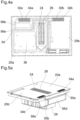
- FIG. 4 and 5 Another different exhaust outlet tubing 56 is presented with Figs. 4 and 5 , also including the previously described first and second elements 56a, 56b of the exhaust outlet tubing 56.
- the airflow is redirected two times by 90 degrees at the rear side of the combination appliance 10 by tubing elements 56d, 56e towards an exhaust opening 30 arranged at the rear side of the worktop 22 of the cooking hob 12 as an extension of the suction opening 24.
- Both the suction opening 24 and the exhaust opening 30 of this embodiment are arranged on the middle axis of the worktop 22 in axisymmetric way, but their longitudinal axes are arranged orthogonally to each other.
- This solution too, is equipped with an outlet grille 34 preventing items to fall into the exhaust opening 30.
- FIGs. 4a and 5a An alternative solution, which may be preferred over the previous one, is presented with Figs. 4a and 5a .
- two exhaust openings 30a, 30b with allocated outlet grilles 34a, 34b are arranged close to the rear edge of the worktop 22 of the combination appliance 10.
- the two exhaust openings 30a, 30b may be arranged symmetrically to the central axis of the combination appliance 10, as illustrated in Figs.
- a first one 30a of the exhaust openings may directly communicate with tubing element 56d and a second one 30b may communicate with tubing element 56e.
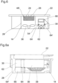
- Fig. 6 shows schematically a longitudinal section and Fig. 6a a real embodiment with transparent casing of a combination appliance 10 similar to the embodiments of Figs. 1 to 5 , illustrating a first example of an air channel system provided for an operation of the combination appliance 10 in a first operating mode, in which cooking fumes are sucked from the cooking regions 20a, 20b, as well as in a second operating mode, in which the air inside of the kitchen room is purified, which first and second operating modes are usually operated at different times.
- the embodiment according to Fig. 6 differs from the previously described embodiments in that the filter device 48' is merely equipped with a grease filter element, while an odour filter element, which in the present example is a charcoal filter 62, is arranged downstream of the fan 36 and upstream of the exhaust opening 30.
- the channel section between fan outlet 54 and exhaust opening 30, which houses the charcoal filter 62 forms a main channel section, which is passed through in both the first operating mode and in the second operating mode.
- an auxiliary channel section is provided, which is only passed through by an airflow in the second operating mode, i. e. the air purifying mode.
- an air purifying filter element more specifically a HEPA filter element 66, is arranged.
- the air purifying subsystem is not working during the first operating mode, i. e. the cooking fumes extraction mode.
- the auxiliary channel section in which this air purifying subsystem is arranged, is disconnected from the airflow.
- This disconnection is performed by inlet and outlet valves 64, 64', which are configured to selectively open and close the auxiliary channel section.
- the structure of the embodiment according to Fig. 6a differs from that one of Fig. 6 in a horizontally mirrored design (i. e. with vertical mirror axis), as well as the charcoal filter 62 being positioned above the HEPA filter element 66.
- inlet and outlet valves 64, 64' are not shown in detail in Fig. 6a , but only indicated.
- Fig. 7 illustrates a combination appliance 10 analogous to the embodiment of Fig. 6 , but the embodiment of Fig. 7 comprises a second example of an air channel system.
- the grease and odour filter elements are again combined and housed in the filter device 48.
- the auxiliary channel section opens out into an auxiliary outlet 72, which is an outlet opening separate from the exhaust opening 30.
- shut-off valves 68 are implemented, which allow the airflow either to pass through the exhaust opening 30, or to take a way through the auxiliary channel section with passing through the HEPA filter element 66.
- the third example of an air channel system is similar to that one as illustrated in Fig. 7 .
- the auxiliary outlet 72 of the second example is arranged on the top side of the combination appliance 10, in particular in the worktop 22 of the cooking hob 12, similar to what is shown in Figs. 4 and 5
- the auxiliary outlet 72 of the third example is arranged in the plinth area, similar to what is shown by exhaust opening 30 in Fig. 1 . Due to the extended length of the auxiliary channel section of the third example, an arrangement of two air purifying filters is possible, either by using two HEPA filters 66 in series, as shown, or by using a combination with another type of an air purifying filter element (e. g. a PECO, an Ulpa or a fluid filter means) instead.
- an air purifying filter element e. g. a PECO, an Ulpa or a fluid filter means
- FIG. 9 a flow diagram of an algorithm for an automated control of an extraction device 14 for its operation in an air purifying mode is shown.
- the user selects, whether the extraction device 14 generally shall perform an air purification operation, at decision step “B” selection has to be made, whether by selection “m” the user wants to manually initiate this kind of operation or whether the control electronics 52 by selection "a” shall trigger an automatic activation. If the manual initiation by "m” is chosen, the user has to initiate the operation by process step “C” with setting at least one parameter, in particular setting a timer value, i. e. entering a time interval, how long the air purification shall be performed.
- a timer value i. e. entering a time interval
- a related input to an air purification board which may be a part of the circuit of the control electronics 52, is provided and by process step “D” an implemented valve 64, 64', 68, 70, depending on the previously described example embodiment, is opened for providing access to the auxiliary channel section.
- the fan 36 is started to perform a "breeze mode", which is an operation with low conveying capacity. If the automatic activation by selection "a” is chosen, the user further has to select at decision step “e”, whether the automatically initiated air purification operation shall be based on a timer value, by setting selection "t”, so that the control electronics 52 will initiate the operation as soon as a down counter provides a signal to have reached value "zero".
- a sensor signal is awaited, which indicates a measuring incidence.
- Decision steps “F” and “G” are program loops, with which the respective occurrence, i. e. timer value "zero” or set sensor value measured, is awaited. After entry of the awaited occurrence the algorithm is continued with previously described process step "D".
- Said sensor value is the result of a measurement of the air quality level, and it may be anyone of the measurement results of receiving a predetermined humidity level and/or a predetermined value of a temperature and/or volatile organic compound (TVOC).
- a program loop by decision step "H” is started, which awaits anyone of the incidences (i) “timer reached predetermined operation time", (ii) "sensor signal below predetermined reference signal” or “iii” "user interface input signal for operating a cooking program”.
- the valve 64, 64', 68, 70 is closed by process step “I” and the fan 36 is either switched off or, in the event of the user selected the start of a cooking program, see incidence "i", the fan 36 is operated with a respective higher power level.
- the algorithm for air purification process is finalized at process end "J".
Landscapes
- Engineering & Computer Science (AREA)
- Chemical & Material Sciences (AREA)
- Combustion & Propulsion (AREA)
- Mechanical Engineering (AREA)
- General Engineering & Computer Science (AREA)
- Ventilation (AREA)
- Filtering Of Dispersed Particles In Gases (AREA)
Abstract
Description
- The present invention relates to an extraction device comprising an air channel system, an air transportation means and a filter unit according to the preamble of claim 1. The present invention also relates to a combination appliance comprising a cooking hob and an extraction device according to the preamble of claim 13. The present invention further relates to a method for operating an extraction device or a combination appliance according to the preamble of
claim 14. - During the performance of cooking activities under use of a cooking hob, cooking vapours are generated, which are distributed over the cooking area. In order to avoid these cooking vapours to be spread throughout the entire kitchen space, an arrangement of an extraction device, particularly an extractor hood, is common. Said extraction device is operated in parallel to the cooking hob, thereby sucking in those cooking vapours in order to filter out particles and tiny droplets from the vapours and/or to blow the vapours to the outside of the building. Such an extractor hood may be arranged above the cooking area or it may be included in a combination appliance, which is a configuration of an entity including the extractor hood and the cooking hob. Such kind of extraction device is usually arranged as an extraction unit below a worktop of the related cooking hob and it comprises at least one fan for sucking air from the cooking area through an opening arranged in the worktop, which air flows through an air channel system, in which a filter unit is arranged for a removal of cooking fumes, to an exhaust outlet.
- On the other hand, in order to increase the home comfort, there is a nascent trend towards a steady improvement of the indoor air quality in residential buildings. Respective devices are known for air conditioning and air purification, which devices are equipped with different types of fluids or air filters providing a removal of pollution from the indoor air.
- It is also known to include both said task performances, i. e. both the extraction of cooking fumes and the purification of indoor air, in only one unit. In particular,
CN109323311A discloses an integrated stove, which is capable of performing an extraction of cooking vapours according to a first functionality and of performing an air purification according to a second functionality. To this end, a common inlet opening is provided and, after passing a common filter unit, the conveyed air is forwarded to a smoking box and, consecutively, to an air duct system. The air duct system splits up into a main end pipe for an outdoor exhausting of cooking fumes and an auxiliary end pipe for a recirculation of purified room air. In order to control the airflow direction, a switching assembly is included for selectively opening and closing passages to the main and auxiliary pipes. - It is an object of the present invention to provide an extraction device and/or a combination appliance performing an improved air purification without the need of an increased maintenance effort. Further, a method for operating an extraction device or a combination appliance shall be provided, which support said improved air purification performance of the extraction device and/or of the combination appliance compared with a need of only limited maintenance effort to be performed by a user.
- The object is achieved for an extraction device according to the preamble of claim 1 by the features of the characterizing part of claim 1.
- An extraction device comprises an air channel system for air conveyance with at least one suction opening and at least one exhaust opening, an air transportation means, in particular an air blower, and a filter unit comprising at least one first filter element. The extraction device is configured to be operated in a first operating mode and in a second operating mode. The air channel system comprises a branch or junction. The air channel system further comprises at least one shut-off means, which provides access to at least a second air conduit, when the extraction device is operated in the second operating mode. The shut-off means is in particular at least one shut-off valve, preferably an electrical shut-off valve. As an alternative to the shut-off means, the air channel system further comprises a changeover means with a first outlet and a second outlet for guiding at least a portion of the conveyed air either through the first outlet to a first air conduit or to the at least one exhaust opening, or through the second outlet to a second air conduit. Said conveyed air or conveyed air portion is guided to the first air conduit or to the at least one exhaust opening, when the extraction device is operated in the first operating mode. On the other hand, the at least a portion of the conveyed air is guided to the second air conduit, when the extraction device is operated in the second operating mode. The branch or junction and the changeover means are arranged at a first end of the first air conduit and at a first end of the second air conduit. Preferably, the branch or junction and the changeover means or the shut-off means are arranged downstream of the air transportation means. According to the present invention, at least one air treatment means is arranged in the second air conduit. Additionally, or alternatively, the at least one air treatment means impinges on the air guided through the second air conduit. Said changeover means may be a changeover valve, preferably an electrical changeover valve. With such air treatment means the air may be treated in a particular manner, especially in addition to the filtering effect performed by the filter unit comprising the at least one first filter element.
- A preferred embodiment of the present invention is characterized in that the filter unit, which comprises the at least one first filter element, is a first filter device, and in that the air treatment means is or comprises a second filter device, which particularly comprises a second filter element.
- The first operating mode may be a cooking fumes extraction mode, in which the air transportation means aspirates air comprising cooking fumes from an area above a cooking zone. Moreover, the second operating mode may be an air purifying mode, in which the air transportation means aspirates air from a space, in which the extraction device is arranged.
- According to an embodiment, the at least one air treatment means, which is particularly the second filter device, comprises an air purifying filter means. The air purifying filter means preferably includes an odour and/or a dust filter unit, especially a VOC or TVOC filter unit eliminating any kind of volatile organic compounds. More specifically, the air purifying means particularly comprises at least one of a HEPA filter, a PECO filter, an Ulpa filter, and a fluid filter means.
- The extraction device favourably comprises a common suction opening, which is provided for the operation of the extraction device both in the first operating mode and in the second operating mode. The common suction opening is preferably arranged or arrangeable on a cooktop of a cooking hob, which is assigned to the extraction device. According to an even more preferred embodiment, the common suction opening is arranged or arrangeable in a centre zone of the cooktop, which particularly is a glass ceramic cooktop.
- According to embodiments, a first exhaust opening is arranged at a second end of the first air conduit, and a second exhaust opening is arranged at a second end of the second air conduit. In particular, the second exhaust opening is arranged or arrangeable on a cooktop, particularly a glass ceramic cooktop, of a cooking hob, which cooking hob is assigned to the extraction device. Alternatively, the second exhaust opening is arranged or arrangeable on a worktop of a kitchen cabinet, in which the extraction device is mounted or mountable. As a further alternative, the second exhaust opening may be arranged in a bottom area of a cabinet, in which the extraction device may be arranged or arrangeable. Another, alternative or additional, particular embodiment provides for a first exhaust opening that includes at least a first first exhaust opening and a second first exhaust opening, which first first and second first exhaust openings are spaced from one another and/or which are spaced from the suction opening. Other specific, additional or alternative, implementations provide for first and second exhaust openings that are arranged that way, i. e. spaced from one another and/or spaced from the suction opening. In addition, or as an alternative to the spaced positioning, at least one of the first and second exhaust openings may comprise orientable air guiding means, e. g. flaps, in order to avoid short-circuit air recirculation causing exhaust air to be directly aspirated through the suction opening.
- One specifically preferred embodiment is characterized in that the suction opening and at least one of the first and second exhaust openings are arranged on a common surface, particularly on the cooktop of the cooking hob. Such kind of joint positioning may be favourable with respect to an easy-to-install solution. The filter unit, which comprises the at least one first filter element, may be arranged downstream, in particular directly downstream, of the suction opening and/or it may be accessible through the suction opening. Said filter unit is particularly the first filter device, which preferably comprises a grease filter element and/or an odour filter element. Moreover, the at least one air treatment means may be arranged upstream, in particular directly upstream, of the exhaust opening, which is particularly the second exhaust opening, and/or it may be accessible through the exhaust opening. More specifically, the exhaust opening is the second exhaust opening. The at least one air treatment means may comprise the second filter device and/or the second filter element.
- In some implementations, the first operating mode, which is particularly the cooking fumes extraction mode, is a recirculation mode, i. e. the air is conveyed in a recirculated flow. This may also include, that the at least one suction opening and the at least one exhaust opening are arranged in the same room or space, in particular a kitchen room. In some other implementations, said first operating mode is an exterior release mode. According to that, provisions may be made that the at least one suction opening and the at least one exhaust opening are arranged in different rooms or spaces. The at least one exhaust opening, in particular the first exhaust opening, is preferably arranged outside of the building.
- On the other hand, the second operating mode, which is particularly said air purifying mode, is preferably a recirculation mode. Accordingly, the at least one suction opening and the at least one exhaust opening, in particular the second exhaust opening, are arranged in the same room or space. Such recirculation, especially in a nearly enclosed space, may provide for a gradually purified room atmosphere.
- Another embodiment is characterized in that both the first air conduit and the second air conduit merge into a common exhaust opening. That way, only one opening outlet has to be provided, which may also reduce the effort for the installation of the extraction device in a kitchenette. In the same spirit, but with a different structure, both the first air conduit and the second air conduit may merge into a common air channel end section. Accordingly, the common air channel end section may open into said common exhaust opening for an air outlet. Preferably, an air conduit closing means is included configured for closing at least a second end of the second air conduit, when the extraction device is operated or operable in the first operating mode, which may be the cooking fumes extraction mode. According to a preferred embodiment, the second end of the second air conduit is arranged downstream of the air treatment means. Moreover, said air closing means is particularly a second changeover valve having a first inlet and a second inlet. With said air closing means any return flow of air into the second air conduit via its second end may be preventable, and the second air conduit may be closed off from its both ends.
- The second operating mode, in particular the air purifying mode, may be an operating mode, in which the air transportation means is operated with low power and/or with low conveying capacity. This may increase the purification effect, what means that the respective air treatment means may operate in an optimized way, when the air throughput is reduced. Advantageously, the second operating mode is performed at the end of a cooking process or on a user's specific selection.
- The object is achieved for a combination appliance according to the preamble of claim 13 by the characterizing features of claim 13.
- According to a further aspect of the invention, a combination appliance is provided, which comprises a cooking hob for performing cooking processes and an extraction device according to anyone of the herein disclosed embodiments. The combination appliance is configured to be electively operated in a first operating mode, which may be a cooking fumes extraction mode, or in a second operating mode, which may be an air purifying mode. The operation of the combination appliance, and particularly of the included extraction device, is preferably performed based on a user's selection and/or by automated activation by means of a software application. Said software application may include a routine of receiving an input of a timer and/or of a sensor signal, and the operation of the extraction device is particularly triggered by said timer and/or sensor signal.
- It shall be noted, that all herein disclosed embodiments, in particular the disclosed features and components, related to an extraction device shall be understood to also relate to a combination appliance, in particular when reference is made to any features and/or functionalities of a cooking hob.
- Finally, the object is achieved for a method for operating an extraction device or a combination appliance according to the preamble of
claim 14 by the characterizing features ofclaim 14. - A method for operating an extraction device or a combination appliance according to anyone of the embodiments as disclosed herein is operable by a first operating mode, in which cooking fumes are removed from a cooking zone or area, and by a second operating mode, in which air is aspirated from a space, where the extraction device or the combination appliance is arranged. The second operating mode is provided for an air purification, in particular of ambient air, more specifically of the air in the room, e. g. a kitchen, forming the installation location of the extraction device or the combination appliance. The method is determined by air being sucked in through at least one suction opening and being conveyed in an air channel system from the at least one suction opening to at least one exhaust opening of the air channel. Further provision is made for at least a portion of the conveyed air being guided at a branch or junction, according to a first aspect, by opening and/or closing at least one shut-off means at least to a second air conduit, when the extraction device is operated in the second operating mode. In contrast to this implementation of a shut-off means, a changeover means may be implemented. In this case, said at least a portion of the conveyed air may be guided at the branch or junction to a first air conduit or to a second conduit. In order to achieve this guidance, said changeover means comprises a first outlet and a second outlet, and the changeover means causes the air either to take the way to a first air conduit or to at least one of the at least one exhaust opening via the first outlet, or to take the way to a second air conduit via the second outlet. The first outlet is accessible to the airflow, when the extraction device is operated in the first operating mode, and the second outlet is accessible, when the extraction device is operated in the second operating mode. Each one of the first air conduit and the second air conduit opens into at least one of the at least one exhaust opening, which may mean either that the first and second air conduit open into a common space or chamber that forms or is arranged upstream of a common exhaust opening, or that at least one first exhaust opening allocated to the first air conduit and at least one second exhaust outlet allocated to the second air conduit are provided. According to the present invention, at least one air treatment means impinges on the air for the purpose of air purification, when the extraction device or the combination appliance is operated in the second operating mode. During said second operating mode the air is particularly guided through the second air conduit. Moreover, said air treatment means may be an air purifying filter means, which preferably includes an odour and/or a dust filter unit, especially a VOC or TVOC filter unit eliminating any kind of volatile organic compounds. More specifically, the air purifying means particularly comprises at least an air treatment filter, particularly at least a HEPA filter, a PECO filter, an Ulpa filter, and/or a fluid filter means.
- One embodiment of the method is characterized in that the shut-off means, preferably being a shut-off valve, is switched between an open state and a closed state by means of an electrical control signal. If a changeover means is implemented instead of a shut-off means, which changeover means is preferably a changeover valve, it is switched from the first outlet to the second outlet or vice versa, i. e. from the second outlet to the first outlet, by means of an electrical control signal. The control signal is based on a user's manual activation or on an automatic activation. In case of the manual activation, the user selects at least one of the first operating mode or the second operating mode. Said manual activation is particularly performed on a control device of the extraction device or the combination appliance or on an input means of a smart device, such as a smart phone or a tablet computer. For signal transmission, preferably a wireless connection is used. In the alternative, i. e. in the case of an automatic activation, a specific algorithm implemented in a software application may be provided for controlling the selection of at least one of the first and second operating modes. The selection may be based on a timer signal and/or on a sensor signal, which sensor signal detects at least one status value of the conveyed air. The status value is particularly at least one of a humidity value, a temperature value and/or a VOC value.
- The method may be established such that a user can selectively chose either the first operating mode or the second operating mode, i. e. the changeover means may be switched to either the first outlet or to the second outlet. In case of selection of the first operating mode, also a related power level and/or air flow quantity may be selectable by a respective user input. In case of selection of the second operating mode, the operation may be immediately started or means for a delayed start may be provided.
- On the other hand, the method may be established that a software application can selectively trigger either the first operating mode or the second operating mode. In case of automatic selection of the first operating mode, the operation of the extraction device may be triggered by a specific hob control signal, e. g. based on a selected power level of an operated cooking zone or based on a specific cooking program selected by the user. In case of an automatic selection of the second operating mode, a timer and/or a sensor signal may not only trigger the second operating mode to be selected, but also any parameters for the operation of the extraction device may be chosen and/or set.
- The method described herein, particularly the air functionalities, may be operated and/or controlled on a remote basis, especially by means of a software application, wherein any known connectivity means, e. g. mobile and/or wireless connectivity solutions, may be used.
- Novel and inventive features of the present invention are set forth in the appended claims.
- The present invention will be described in further detail with reference to the drawings, in which
- Fig. 1
- is a perspective view of a combination appliance comprising a cooking hob and a downdraft extraction device installed in a kitchen cabinet;
- Fig. 2
- is a cross-sectional perspective view of the disassembled combination appliance of
Fig. 1 with a frontal surface cut away and including a removable filter device; - Fig. 3
- is a cross-sectional view of a detail of the combination appliance of
Figs. 1 and2 , indicated by III - III inFig. 2 ; - Fig. 4
- is a top view of the combination appliance of
Fig. 1 with transparent cooktop; - Fig. 4a
- is a top view of the combination appliance of
Fig. 4 , but with two exhaust openings; - Fig. 5
- is a perspective view of the rear side of the combination appliance according to
Fig. 4 ; - Fig. 5a
- is a non-transparent perspective view of the rear side of the combination appliance according to
Fig. 4a ; - Fig. 6
- shows schematically a longitudinal section of a combination appliance similar to the embodiment of
Figs. 1 to 5 , illustrating a first example of an air channel system; - Fig. 6a
- is an illustration of a real embodiment similar to the schematic combination appliance of
Fig. 6 ; - Fig. 7
- is a schematic illustration analogous to
Fig. 6 , but illustrating a second example of an air channel system; - Fig. 8
- is a schematic illustration analogous to
Fig. 6 , but illustrating a third example of an air channel system; - Fig. 8a
- is a side view of a partly transparent combination appliance similar to the schematic illustration according to
Fig. 8 ; - Fig. 8b
- is a perspective view of the combination appliance of
Fig. 8a in a non-transparent illustration; and - Fig. 9
- illustrates a flow diagram of an algorithm for an automated control of an extraction device for its operation in an air purifying mode.
- In all figures the same or equivalent part are marked with the same reference numbers.
-
Fig. 1 illustrates acombination appliance 10 comprising acooking hob 12 and adowndraft extraction device 14 installed in akitchen cabinet 16. Thecooking hob 12 is installed in a cut-out of akitchen countertop 18 forming a top cover plate of thekitchen cabinet 16. According to a first functionality of thecombination appliance 10, thedowndraft extraction device 14 is configured to take away cooking vapours generated during cooking processes, in particular when cooking with uncovered cookware. Thecooking hob 12 comprisescooking regions worktop 22 of thecooking hob 12, which left and right halves are separated from each other by asuction opening 24 for an intake of the cooking vapours, thesuction opening 24 being arranged alongside a worktop centreline. Thesuction opening 24 is covered by acover grid 26 for preventing items, e. g. cookware, to fall into thesuction opening 24. - A
casing 28 of theextraction device 14 is shown inFig. 1 in transparent illustration. Said casing 28 provides a closed outer shell or first channel section for a flow of the sucked-in air including the cooking vapours on their way from thesuction opening 24 to anexhaust opening 30 in abase area 32 of thekitchen cabinet 16. Saidexhaust opening 30 is also covered, specifically by anoutlet grille 34. - The flow of the sucked-in air through the
extraction device 14 is driven by the operation of anextraction fan 36 arranged inside of thecasing 28. Saidextraction fan 36 comprises a bottom-sided intake opening 38 for sucking the conveyed air from the interior space of thecasing 28. - The conveyed air exits the
extraction fan 36 at anoutlet 54 at the fan rear side, whichoutlet 54 is connected to a first end of anair duct 44 designed as a rectangular tube. Theair duct 44 forms a second channel section arranged downstream the previously mentioned first channel section. Directly at the passage from thefan outlet 54 to theair duct 44, an air duct bending by 90 degrees is implemented, which redirects the air flow from horizontal to vertical downwards. Theair duct 44 may be guided alongside a rear side of thekitchen cabinet 16 and may be bent again by 90 degrees close to a rear lower edge of thekitchen cabinet 16 in order to direct the airflow towards exhaust opening 30 in thebase area 32 of thekitchen cabinet 16. Accordingly, the second end of theair duct 44 is connected to theexhaust opening 30. The embodiment illustrated inFig. 1 shows a solution of theair duct 44 with an inclined section of its downwardly directed portion, directed slightly to the right. Naturally, a solution with said portion arranged in an exact vertical direction is considerable as well. - The course of the cooking vapours from the cooking area through the
extraction device 14 to a re-entry into room air is illustrated inFig. 1 by dottedarrows 461 to 465. On their way through theextraction device 14, the cooking vapours pass through afilter device 48, which is arranged downstream directly behind thesuction opening 24. Saidfilter device 48 is adapted to filter particles and droplets, in particular grease particles and droplets as well as moisture and odorous substances, out of the cooking vapours, in that purifying the cooking vapours in order to feed filtered air back to the room air. - The cross-sectional view of
Fig. 2 further shows twopower boards 50, one for theleft cooking region 20a and one for theright cooking region 20b, thepower boards 50 providing cooking zones in the left andright cooking regions cooking hob 12 is an induction cooking hob and the cooking zones are defined by induction coils (not shown) that are arranged below theworktop 22 of thecooking hob 12. Attached to the bottom side of thepower board 50 assigned to theright cooking region 20b, a further circuit board is arranged forming acontrol electronics 52 for thecombination appliance 10. - According to a second functionality of the
combination appliance 10, thedowndraft extraction device 14 is further configured to take away pollution from the indoor air of the room, more specifically a kitchen space, in which thecombination appliance 10 is arranged. This type of air purification functionality forms a second operating mode performable by thecombination appliance 10, more specifically by theextraction device 14, while the above-described first functionality of removal of cooking fumes forms a first operating mode. First and second operating modes will be described in more detail further down below. -
Fig. 3 illustrates a cross-sectional view of a detail of thecombination appliance 10, which detail is arranged at a rear side showing particularly an exhaust outlet tubing 56, including afirst element 56a for a connection to thefan outlet 54, asecond element 56b, which can be cut to length depending on the mounting conditions provided by thekitchen cabinet 16, and a third element comprising a flange for a fixation on cabinetrear wall 58, which shall be provided with apassage opening 60 in the area of fixation of said flange. That way, an exhaust opening oroutlet 30 is provided, which is positioned differently to that one of the embodiment ofFig. 1 . With such exhaust outlet tubing 56, an elaborate arrangement of anair duct 44 as with the embodiment ofFig. 1 is avoided. Instead, the exhaust air is blown into the space between the cabinetrear wall 58 and a kitchen wall. - Another different exhaust outlet tubing 56 is presented with
Figs. 4 and 5 , also including the previously described first andsecond elements Fig. 3 , the airflow is redirected two times by 90 degrees at the rear side of thecombination appliance 10 bytubing elements exhaust opening 30 arranged at the rear side of theworktop 22 of thecooking hob 12 as an extension of thesuction opening 24. Both thesuction opening 24 and theexhaust opening 30 of this embodiment are arranged on the middle axis of theworktop 22 in axisymmetric way, but their longitudinal axes are arranged orthogonally to each other. This solution, too, is equipped with anoutlet grille 34 preventing items to fall into theexhaust opening 30. - An alternative solution, which may be preferred over the previous one, is presented with
Figs. 4a and 5a . Instead of the only oneexhaust opening 30 according toFigs. 4 and 5 , positioned in close proximity to thesuction opening 24 and specifically on and symmetrically to the central axis of thecombination appliance 10, twoexhaust openings outlet grilles worktop 22 of thecombination appliance 10. Also the twoexhaust openings combination appliance 10, as illustrated inFigs. 4a and 5a , but they are spaced from said central axis, and hence spaced from thesuction opening 24, so that a short-circuit air recirculation is avoided. A first one 30a of the exhaust openings may directly communicate withtubing element 56d and a second one 30b may communicate withtubing element 56e. -
Fig. 6 shows schematically a longitudinal section andFig. 6a a real embodiment with transparent casing of acombination appliance 10 similar to the embodiments ofFigs. 1 to 5 , illustrating a first example of an air channel system provided for an operation of thecombination appliance 10 in a first operating mode, in which cooking fumes are sucked from thecooking regions - The embodiment according to
Fig. 6 differs from the previously described embodiments in that the filter device 48' is merely equipped with a grease filter element, while an odour filter element, which in the present example is acharcoal filter 62, is arranged downstream of thefan 36 and upstream of theexhaust opening 30. The channel section betweenfan outlet 54 andexhaust opening 30, which houses thecharcoal filter 62, forms a main channel section, which is passed through in both the first operating mode and in the second operating mode. In parallel to this main channel section, an auxiliary channel section is provided, which is only passed through by an airflow in the second operating mode, i. e. the air purifying mode. In this auxiliary channel section, an air purifying filter element, more specifically aHEPA filter element 66, is arranged. In order to avoid a short time saturation of thisHEPA filter element 66 due to grease particles comprised in the airflow, the air purifying subsystem is not working during the first operating mode, i. e. the cooking fumes extraction mode. Hence, the auxiliary channel section, in which this air purifying subsystem is arranged, is disconnected from the airflow. This disconnection is performed by inlet andoutlet valves 64, 64', which are configured to selectively open and close the auxiliary channel section. The structure of the embodiment according toFig. 6a differs from that one ofFig. 6 in a horizontally mirrored design (i. e. with vertical mirror axis), as well as thecharcoal filter 62 being positioned above theHEPA filter element 66. Moreover, inlet andoutlet valves 64, 64' are not shown in detail inFig. 6a , but only indicated. -
Fig. 7 illustrates acombination appliance 10 analogous to the embodiment ofFig. 6 , but the embodiment ofFig. 7 comprises a second example of an air channel system. In this second example, the grease and odour filter elements are again combined and housed in thefilter device 48. In contrast to the first example, the auxiliary channel section opens out into anauxiliary outlet 72, which is an outlet opening separate from theexhaust opening 30. In accordance with this separation of theexhaust outlets valves 68 are implemented, which allow the airflow either to pass through theexhaust opening 30, or to take a way through the auxiliary channel section with passing through theHEPA filter element 66. - The third example of an air channel system, presented with
Figs. 8 ,8a and 8b in different formats of presentation, is similar to that one as illustrated inFig. 7 . However, while theauxiliary outlet 72 of the second example is arranged on the top side of thecombination appliance 10, in particular in theworktop 22 of thecooking hob 12, similar to what is shown inFigs. 4 and 5 , theauxiliary outlet 72 of the third example is arranged in the plinth area, similar to what is shown byexhaust opening 30 inFig. 1 . Due to the extended length of the auxiliary channel section of the third example, an arrangement of two air purifying filters is possible, either by using two HEPA filters 66 in series, as shown, or by using a combination with another type of an air purifying filter element (e. g. a PECO, an Ulpa or a fluid filter means) instead. - Finally, by
Fig. 9 a flow diagram of an algorithm for an automated control of anextraction device 14 for its operation in an air purifying mode is shown. Starting at symbol "A", where the user selects, whether theextraction device 14 generally shall perform an air purification operation, at decision step "B" selection has to be made, whether by selection "m" the user wants to manually initiate this kind of operation or whether thecontrol electronics 52 by selection "a" shall trigger an automatic activation. If the manual initiation by "m" is chosen, the user has to initiate the operation by process step "C" with setting at least one parameter, in particular setting a timer value, i. e. entering a time interval, how long the air purification shall be performed. After user's respective selection, a related input to an air purification board, which may be a part of the circuit of thecontrol electronics 52, is provided and by process step "D" an implementedvalve fan 36 is started to perform a "breeze mode", which is an operation with low conveying capacity. If the automatic activation by selection "a" is chosen, the user further has to select at decision step "e", whether the automatically initiated air purification operation shall be based on a timer value, by setting selection "t", so that thecontrol electronics 52 will initiate the operation as soon as a down counter provides a signal to have reached value "zero". In the alternative, if the user chooses selection "s", a sensor signal is awaited, which indicates a measuring incidence. Decision steps "F" and "G" are program loops, with which the respective occurrence, i. e. timer value "zero" or set sensor value measured, is awaited. After entry of the awaited occurrence the algorithm is continued with previously described process step "D". Said sensor value is the result of a measurement of the air quality level, and it may be anyone of the measurement results of receiving a predetermined humidity level and/or a predetermined value of a temperature and/or volatile organic compound (TVOC). Independently from a manual or an automatic initiation of the air purification process, after its start by process step "D" a program loop by decision step "H" is started, which awaits anyone of the incidences (i) "timer reached predetermined operation time", (ii) "sensor signal below predetermined reference signal" or "iii" "user interface input signal for operating a cooking program". With occurrence of anyone of "i" to "iii", thevalve fan 36 is either switched off or, in the event of the user selected the start of a cooking program, see incidence "i", thefan 36 is operated with a respective higher power level. The algorithm for air purification process is finalized at process end "J". - Although illustrative embodiments of the present invention have been described herein with reference to the accompanying drawings, it is to be understood that the present invention is not limited to these precise embodiments, and that various other changes and modifications may be affected therein by one skilled in the art without departing from the scope or spirit of the invention. All such changes and modifications are intended to be included within the scope of the invention as defined by the appended claims.
- Moreover, features which are described in the context of separate aspects and embodiments of the invention may be used together and/or be interchangeable. Similarly, features described in the context of a single embodiment may also be provided separately or in any suitable sub-combination.
-
- 10
- combination appliance
- 12
- cooking hob
- 14
- downdraft extraction device
- 16
- kitchen cabinet
- 18
- kitchen countertop
- 20a,20b
- cooking regions
- 22
- worktop
- 24
- suction opening
- 26
- cover grid
- 28
- casing
- 28a,28b
- first and second casing parts
- 30,30a,30b
- exhaust openings/outlets
- 32
- base area
- 34,34a,34b
- outlet grilles
- 36
- extraction fan
- 38
- intake opening
- 42
- fan housing
- 44
- air duct
- 461 to 5
- arrows indicating air flow
- 48,48'
- filter device
- 50
- power boards
- 52
- control electronics
- 54
- fan outlet
- 56
- exhaust outlet tubing
- 56a,56b,56c, 56d, 56e
- tubing elements
- 58
- cabinet rear wall
- 60
- passage opening
- 62
- charcoal filter
- 64,64'
- inlet valve, outlet valve
- 66
- HEPA filter
- 68
- shut-off valves
- 70
- changeover valve
- 72
- auxiliary outlet
- A
- process start
- B,E,F,G,H
- decision step
- C,D,I
- process step
- J
- process end
- a,m,s,t
- selections
- n
- result "no"
- y
- result "yes"
Claims (15)
- An extraction device (14) comprising- an air channel system for air conveyance with at least one suction opening (24) and at least one exhaust opening (30, 30a, 30b, 72),- an air transportation means (36), in particular an air blower,- a filter unit (48, 48') comprising at least one first filter element,
wherein the extraction device (14) is configured to be operated in a first operating mode and in a second operating mode, wherein the air channel system comprises a branch or junction and- at least one shut-off means (64, 64', 68), in particular at least one shut-off valve, preferably an electrical shut-off valve, the at least one shut-off means (64, 64', 68) providing access to at least a second air conduit, when the extraction device (14) is operated in the second operating mode,
or- a changeover means (70), in particular a changeover valve, preferably an electrical changeover valve, the changeover means (70) having a first outlet and a second outlet for guiding at least a portion of the conveyed air either through the first outlet to a first air conduit or to the at least one exhaust opening (30, 30a, 30b), when the extraction device (14) is operated in the first operating mode, or through the second outlet to a second air conduit, when the extraction device (14) is operated in the second operating mode, and wherein the branch or junction and the changeover means (70) are arranged at a first end of the second air conduit and particularly at a first end of the first air conduit,the branch or junction and the shut-off (64, 64', 68) or changeover (70) means preferably being arranged downstream of the air transportation means (36),
characterized in that
at least one air treatment means (66) is arranged in the second air conduit and/or impinges on the air guided through the second air conduit. - The extraction device (14) according to claim 1,
characterized in that
the filter unit (48, 48') comprising the at least one first filter element is a first filter device and the air treatment means (66) is or comprises a second filter device, which particularly comprises a second filter element. - The extraction device (14) according to claim 1 or 2,
characterized in that
the first operating mode is a cooking fumes extraction mode, in which the air transportation means (36) aspirates air comprising cooking fumes from an area above a cooking zone or area (20a, 20b), and the second operating mode is an air purifying mode, in which the air transportation means (36) aspirates air from a space, in which the extraction device (14) is arranged. - The extraction device (14) according to anyone of the preceding claims,
characterized in that
the at least one air treatment means (66), in particular the second filter device, comprises an air purifying filter means, which preferably includes an odour and/or a dust filter unit, specifically a VOC filter, in particular an air treatment filter, preferably at least- a HEPA filter,- a PECO filter,- an Ulpa filter, and/or- a fluid filter means. - The extraction device (14) according to anyone of the preceding claims,
characterized in that
a common suction opening (24), which is preferably arranged or arrangeable on a cooktop (22), more preferably in a centre zone of the cooktop (22), particularly a glass ceramic cooktop, of a cooking hob (12), which is assigned to the extraction device (14), is provided for the operation of the extraction device (14) in each of the first and second operating modes. - The extraction device (14) according to anyone of the preceding claims,
characterized in that
a first exhaust opening (30, 30a, 30b) is arranged at a second end of the first air conduit, and a second exhaust opening (72) is arranged at a second end of the second air conduit, wherein particularly the first exhaust opening (30)i. includes at least a first first exhaust opening (30a) and a second first exhaust opening (30b), which are spaced from one another and/or which are spaced from the suction opening (24),
and/orii. is arranged or arrangeable- on a cooktop (22), particularly a glass ceramic cooktop, of a cooking hob (12), which is assigned to the extraction device (14),
or- on a worktop (18) of a kitchen cabinet (16), in which the extraction device (14) is mounted or mountable,
or- in a bottom area (32) of a cabinet (16). - The extraction device (14) according to anyone of the preceding claims,
characterized in thatthe filter unit (48, 48') comprising the at least one first filter element, in particular the first filter device, which first filter device preferably comprises a grease filter element and/or an odour filter element, is arranged downstream, in particular directly downstream, of the suction opening (24) and/or is accessible through the suction opening (24), and in thatthe at least one air treatment means (66), in particular comprising the second filter device and/or the second filter element, is arranged upstream, in particular directly upstream, of the exhaust opening (30, 30a, 30b, 72), in particular the second exhaust opening (72), and/or is accessible through the exhaust opening (30, 30a, 30b, 72), in particular the second exhaust opening (72). - The extraction device (14) according to anyone of the preceding claims,
characterized in that
the first operating mode, in particular the cooking fumes extraction mode,- is a recirculation mode, wherein the at least one suction opening (24) and the at least one exhaust opening (30, 30a, 30b, 72) are arranged in the same room or space,
or- is an exterior release mode, wherein the at least one suction opening (24) and the at least one exhaust opening (30, 30a, 30b, 72) are arranged in different rooms or spaces, the at least one exhaust opening (30, 30a, 30b, 72), in particular the first exhaust opening (30, 30a, 30b), preferably being arranged outside of the building. - The extraction device (14) according to anyone of the preceding claims,
characterized in that
the second operating mode, in particular the air purifying mode, is a recirculation mode, wherein the at least one suction opening (24) and the at least one exhaust opening (30, 30a, 30b, 72), in particular the second exhaust opening (72), are arranged in the same room or space. - The extraction device (14) according to anyone of the claims 1 to 5,
characterized in that
both the first air conduit and the second air conduit merge into a common exhaust opening (30, 30a, 30b). - The extraction device (14) according to claim 1 to 5,
characterized in that
both the first air conduit and the second air conduit merge into a common air channel end section, wherein preferably an air conduit closing means (64'), in particular a second changeover valve having a first inlet and a second inlet, is included configured for closing at least a second end of the second air conduit, when the extraction device (14) is operated or operable in the first operating mode, the second end of the second air conduit preferably being arranged downstream of the air treatment means (66). - The extraction device (14) according to anyone of the preceding claims,
characterized in that
the second operating mode, in particular the air purifying mode, is an operating mode, in which the air transportation means (36) is operated with low power and/or with low conveying capacity, the second operating mode preferably being performed at the end of a cooking process or on a user's specific selection. - A combination appliance (10) comprising a cooking hob (12) for performing cooking processes and an extraction device (14) according to anyone of the preceding claims, the combination appliance (10) being configured to be electively operated in a first operating mode, in particular a cooking fumes extraction mode, or in a second operating mode, in particular an air purifying mode, preferably based on a user's selection and/or by automated activation by means of software application, particularly triggered by a timer and/or a sensor signal.
- A method for operating an extraction device (14) according to anyone of the claims 1 to 12 or a combination appliance (10) according to claim 13, which extraction device (14) or combination appliance (10) is operable in a first operating mode, in which cooking fumes are removed from a cooking zone or area (20a, 20b), and by a second operating mode, in which air is aspirated from a space, where the extraction device (14) or the combination appliance (10) is arranged, for an air purification,- wherein air is sucked in through at least one suction opening (24) and conveyed in an air channel system from the at least one suction opening (24) to at least one exhaust opening (30, 30a, 30b, 72),- wherein at least a portion of the conveyed air is guided at a branch or junctiona. by opening and/or closing at least one shut-off means (64, 68) at least to a second air conduit, when the extraction device (14) is operated in the second operating mode,
orb. by a changeover means (70), which comprises a first outlet and a second outlet, either through the first outlet to a first air conduit or to the at least one exhaust opening (30, 30a, 30b), when the extraction device (14) is operated in the first operating mode, or through the second outlet to a second air conduit, when the extraction device (14) is operated in the second operating mode,- and wherein each one of the first air conduit and the second air conduit opens into at least one of the at least one exhaust opening (30, 30a, 30b, 72),characterized in that
at least one air treatment means (66), in particular an air purifying filter means, impinges on the air for the purpose of air purification, when the extraction device (14) or the combination appliance (10) is operated in the second operating mode, in particular when the air is guided through the second air conduit. - The method according to claim 14,
characterized in thata. the shut-off means (64, 64', 68), preferably being a shut-off valve, is switched between an open state and a closed state,
orb. the changeover means (70), preferably being a changeover valve, is switched between the first outlet and the second outlet
by means of an electrical control signal- based on a user's manual activation selecting at least one of the first operating mode or the second operating mode, the manual activation particularly being performed on a control device of the extraction device (14) or the combination appliance (10) or on an input means of a smart device, preferably using a wireless connection,
or- based on automatic activation using a software application, in particular based on a timer signal and/or on a sensor signal detecting at least one status value of the conveyed air, in particular a humidity value, a temperature value and/or a VOC value.
Priority Applications (5)
| Application Number | Priority Date | Filing Date | Title |
|---|---|---|---|
| EP22176878.1A EP4286750A1 (en) | 2022-06-02 | 2022-06-02 | Extraction device, combination appliance and method for operating an extraction device or a combination appliance |
| EP23727844.5A EP4532989A1 (en) | 2022-06-02 | 2023-05-15 | Extraction device, combination appliance and method for operating an extraction device or a combination appliance |
| CN202380042958.4A CN119278339A (en) | 2022-06-02 | 2023-05-15 | Extraction device, combination tool, and method for operating an extraction device or combination tool |
| PCT/EP2023/063015 WO2023232455A1 (en) | 2022-06-02 | 2023-05-15 | Extraction device, combination appliance and method for operating an extraction device or a combination appliance |
| AU2023279053A AU2023279053A1 (en) | 2022-06-02 | 2023-05-15 | Extraction device, combination appliance and method for operating an extraction device or a combination appliance |
Applications Claiming Priority (1)
| Application Number | Priority Date | Filing Date | Title |
|---|---|---|---|
| EP22176878.1A EP4286750A1 (en) | 2022-06-02 | 2022-06-02 | Extraction device, combination appliance and method for operating an extraction device or a combination appliance |
Publications (1)
| Publication Number | Publication Date |
|---|---|
| EP4286750A1 true EP4286750A1 (en) | 2023-12-06 |
Family
ID=81878238
Family Applications (2)
| Application Number | Title | Priority Date | Filing Date |
|---|---|---|---|
| EP22176878.1A Pending EP4286750A1 (en) | 2022-06-02 | 2022-06-02 | Extraction device, combination appliance and method for operating an extraction device or a combination appliance |
| EP23727844.5A Pending EP4532989A1 (en) | 2022-06-02 | 2023-05-15 | Extraction device, combination appliance and method for operating an extraction device or a combination appliance |
Family Applications After (1)
| Application Number | Title | Priority Date | Filing Date |
|---|---|---|---|
| EP23727844.5A Pending EP4532989A1 (en) | 2022-06-02 | 2023-05-15 | Extraction device, combination appliance and method for operating an extraction device or a combination appliance |
Country Status (4)
| Country | Link |
|---|---|
| EP (2) | EP4286750A1 (en) |
| CN (1) | CN119278339A (en) |
| AU (1) | AU2023279053A1 (en) |
| WO (1) | WO2023232455A1 (en) |
Citations (5)
| Publication number | Priority date | Publication date | Assignee | Title |
|---|---|---|---|---|
| GB1137904A (en) * | 1965-10-28 | 1968-12-27 | Jan Prosvic | Air purifiers |
| JPH0225648A (en) * | 1988-07-13 | 1990-01-29 | Matsushita Electric Ind Co Ltd | Flue gas purifying device |
| EP0722071A2 (en) * | 1995-01-12 | 1996-07-17 | TURBOAIR S.p.A. | Suction and/or filtration hood, with improved flow deflection means |
| CN109323311A (en) | 2018-09-19 | 2019-02-12 | 浙江欧琳生活健康科技有限公司 | An integrated stove that can purify the air |
| CN114263944A (en) * | 2020-09-15 | 2022-04-01 | 佛山市顺德区美的洗涤电器制造有限公司 | Range hood, control method and medium |
Family Cites Families (1)
| Publication number | Priority date | Publication date | Assignee | Title |
|---|---|---|---|---|
| KR920003767B1 (en) * | 1988-06-28 | 1992-05-14 | 마쓰시다 덴끼 산교오 가부시끼가이샤 | Flue gas purification device |
-
2022
- 2022-06-02 EP EP22176878.1A patent/EP4286750A1/en active Pending
-
2023
- 2023-05-15 WO PCT/EP2023/063015 patent/WO2023232455A1/en not_active Ceased
- 2023-05-15 CN CN202380042958.4A patent/CN119278339A/en active Pending
- 2023-05-15 AU AU2023279053A patent/AU2023279053A1/en active Pending
- 2023-05-15 EP EP23727844.5A patent/EP4532989A1/en active Pending
Patent Citations (5)
| Publication number | Priority date | Publication date | Assignee | Title |
|---|---|---|---|---|
| GB1137904A (en) * | 1965-10-28 | 1968-12-27 | Jan Prosvic | Air purifiers |
| JPH0225648A (en) * | 1988-07-13 | 1990-01-29 | Matsushita Electric Ind Co Ltd | Flue gas purifying device |
| EP0722071A2 (en) * | 1995-01-12 | 1996-07-17 | TURBOAIR S.p.A. | Suction and/or filtration hood, with improved flow deflection means |
| CN109323311A (en) | 2018-09-19 | 2019-02-12 | 浙江欧琳生活健康科技有限公司 | An integrated stove that can purify the air |
| CN114263944A (en) * | 2020-09-15 | 2022-04-01 | 佛山市顺德区美的洗涤电器制造有限公司 | Range hood, control method and medium |
Also Published As
| Publication number | Publication date |
|---|---|
| EP4532989A1 (en) | 2025-04-09 |
| WO2023232455A1 (en) | 2023-12-07 |
| CN119278339A (en) | 2025-01-07 |
| AU2023279053A1 (en) | 2024-10-31 |
Similar Documents
| Publication | Publication Date | Title |
|---|---|---|
| US11732901B2 (en) | Ventilation apparatus and ventilation system including the same | |
| US5713346A (en) | Apparatus and method for removing fumes from the space above a cooking appliance | |
| US10816219B2 (en) | Modular vent hood blower kit for in-line or external application | |
| US10480798B2 (en) | Recirculating downdraft system for a cooking appliance | |
| US6820609B2 (en) | Low-profile ventilation hood | |
| KR102093869B1 (en) | Range hood with an integrated air purifier | |
| CN1194354A (en) | Microwave oven | |
| US3328560A (en) | Recirculating venting system for domestic oven | |
| KR100946802B1 (en) | Range hood assembly | |
| KR101532225B1 (en) | Withdrawal type range hood installed suction pipes | |
| CN114729754B (en) | Mobile recirculating grill with variable fan drive | |
| EP1843100A2 (en) | Apparatus and method for exhausting smoke with air outlet connected to a central mechanical ventilation system | |
| US11739943B2 (en) | Tabletop cooking assembly | |
| KR100551488B1 (en) | Wall-mounted Microwave | |
| EP4532989A1 (en) | Extraction device, combination appliance and method for operating an extraction device or a combination appliance | |
| KR20060087209A (en) | Exhaust system for cookware | |
| CN116529533A (en) | Combined appliance comprising a cooking hob and a drawing device | |
| US20160131366A1 (en) | Oven range ventilator with microwave compartment | |
| JPH0439550A (en) | Heating and cooking device | |
| EP4198401A1 (en) | Cooking hob and combination appliance comprising a cooking hob | |
| CN115405953A (en) | Integrated cooker, control method thereof and computer-readable storage medium | |
| CN219550616U (en) | Fume exhauster | |
| EP4368899A1 (en) | Fume extraction system and method for operating an extraction device | |
| CN215863629U (en) | Fume exhaust fan | |
| US20250172296A1 (en) | Cooking appliance having a downdraft ventilation system with a deflection blade |
Legal Events
| Date | Code | Title | Description |
|---|---|---|---|
| PUAI | Public reference made under article 153(3) epc to a published international application that has entered the european phase |
Free format text: ORIGINAL CODE: 0009012 |
|
| STAA | Information on the status of an ep patent application or granted ep patent |
Free format text: STATUS: THE APPLICATION HAS BEEN PUBLISHED |
|
| AK | Designated contracting states |
Kind code of ref document: A1 Designated state(s): AL AT BE BG CH CY CZ DE DK EE ES FI FR GB GR HR HU IE IS IT LI LT LU LV MC MK MT NL NO PL PT RO RS SE SI SK SM TR |
|
| STAA | Information on the status of an ep patent application or granted ep patent |
Free format text: STATUS: REQUEST FOR EXAMINATION WAS MADE |
|
| 17P | Request for examination filed |
Effective date: 20240606 |
|
| RBV | Designated contracting states (corrected) |
Designated state(s): AL AT BE BG CH CY CZ DE DK EE ES FI FR GB GR HR HU IE IS IT LI LT LU LV MC MK MT NL NO PL PT RO RS SE SI SK SM TR |