EP4198401A1 - Cooking hob and combination appliance comprising a cooking hob - Google Patents
Cooking hob and combination appliance comprising a cooking hob Download PDFInfo
- Publication number
- EP4198401A1 EP4198401A1 EP21216160.8A EP21216160A EP4198401A1 EP 4198401 A1 EP4198401 A1 EP 4198401A1 EP 21216160 A EP21216160 A EP 21216160A EP 4198401 A1 EP4198401 A1 EP 4198401A1
- Authority
- EP
- European Patent Office
- Prior art keywords
- cooling
- air
- cooking hob
- opening
- cooking
- Prior art date
- Legal status (The legal status is an assumption and is not a legal conclusion. Google has not performed a legal analysis and makes no representation as to the accuracy of the status listed.)
- Pending
Links
Images


Classifications
-
- F—MECHANICAL ENGINEERING; LIGHTING; HEATING; WEAPONS; BLASTING
- F24—HEATING; RANGES; VENTILATING
- F24C—DOMESTIC STOVES OR RANGES ; DETAILS OF DOMESTIC STOVES OR RANGES, OF GENERAL APPLICATION
- F24C15/00—Details
- F24C15/20—Removing cooking fumes
- F24C15/2042—Devices for removing cooking fumes structurally associated with a cooking range e.g. downdraft
-
- F—MECHANICAL ENGINEERING; LIGHTING; HEATING; WEAPONS; BLASTING
- F24—HEATING; RANGES; VENTILATING
- F24C—DOMESTIC STOVES OR RANGES ; DETAILS OF DOMESTIC STOVES OR RANGES, OF GENERAL APPLICATION
- F24C15/00—Details
- F24C15/006—Arrangements for circulation of cooling air
-
- F—MECHANICAL ENGINEERING; LIGHTING; HEATING; WEAPONS; BLASTING
- F24—HEATING; RANGES; VENTILATING
- F24C—DOMESTIC STOVES OR RANGES ; DETAILS OF DOMESTIC STOVES OR RANGES, OF GENERAL APPLICATION
- F24C15/00—Details
- F24C15/10—Tops, e.g. hot plates; Rings
- F24C15/101—Tops, e.g. hot plates; Rings provisions for circulation of air
Definitions
- the present invention relates to a cooking hob comprising a casing, at least one heating system and a cooling system, according to the preamble of claim 1.
- the present invention further relates to a combination appliance comprising a cooking hob and an extraction device according to claim 9.
- the present invention relates to a method for controlling an airflow in a cooking hob or in a combination appliance according to claims 13 and 14.
- a cooling system is implemented in such an appliance.
- the performance of the cooling system can be suboptimal, notably if said cooking hob is a built-in cooking hob.
- Such kind of underper-forming cooling system capacity results in a reduced performance efficiency of the cooking hob, particularly during an executed cooking process.
- disturbances e. g.
- a protective device or unit is implemented, which generally reduces the power of a heating unit compared to a user's selection.
- a typical reason for such kind of underperformance of the cooling system is the fact that the cooling air that is heated up during the cooling process by the components to be cooled and the heated air is returned to the cooling process due to the installation conditions, e. g. by sucking it back by means of a respective ventilation unit, so that the cooling capacity of the cooling air gradually decreases due to a reduction of its absorption capacity of thermal energy.
- Such kind of a cooking hob is particularly known from EP 3 334 248 A1 , which cooking hob includes two power boards including power electronics and a related cooling system.
- the cooling system comprises a cooling element operating as a heat sink for power electronic components.
- a cooling fan for each one of the two power boards is blowing cooling air along the cooling element and the heated air is leaving the cooking hob at its two lateral sides, which include outlet openings.
- air guides are implemented for leading the heated air towards the outlet openings.
- there is no defined air inlet provided so that the heated air that has left the cooking hob housing may be returned to the inlet of the cooling fans, as previously described.
- EP 3 396 255 A1 discloses a combination appliance including an induction cooking hob and an extraction device for cooking fumes.
- the extraction device comprises a downdraft channel section arranged immediately downstream of an inlet opening of the extraction device.
- Heat sink units for power electronic elements of power boards of the cooking hob are attached to outer wall areas of the channel section.
- the heat sink units are cooled using heat conduction through the channel walls, which themselves are cooled by the airflow of the extraction device guided alongside the inner walls of the downdraft channel.
- the airflow arises from a cooking process and, therefore, comprises heated cooking fumes, which results in a reduced cooling performance.
- a cooking hob comprises a casing, a heating system for at least one cooking zone, and a cooling system for heat dissipation from at least a part and/or at least one component of the heating system.
- the cooking hob may be an induction cooking hob.
- the heating system particularly comprises at least one induction heating module and/or the at least one component may be a power electronic component.
- At least a part of the cooling system is arranged in the casing and the cooling system comprises means for providing a flow of cooling air.
- Said means include at least one first inlet opening for an inlet of first inlet air, air transportation and/or air guiding means, and at least one first outlet opening for an outlet of first exhaust air.
- the cooking hob in particular the cooling system of the cooking hob, is configured to let out, particularly to blow out, the first exhaust air through the first outlet opening into a first space or chamber and to take in the first inlet air through the first inlet opening from a second space or chamber.
- the invention further provides that the second space or chamber is separated from the first space or chamber.
- the second space or chamber is the interior of a building or a room and the first chamber is the exterior of the building or the room.
- the cooking hob is designed such that at least one of the following is applicable:
- the kitchen furniture is a kitchenette or a kitchen cabinet.
- the casing may be a single casing or housing including or configured to include the entire heating system, particularly being applicable also for the case of a heating system that has a modular structure and comprises a plurality of heating modules.
- the casing may be understood as a plurality of separate casings, more specifically comprising at least one individual casing for any kind of module in such a modular structure.
- a plurality of first inlet openings may be provided as well, notably a specific first inlet opening may be allocated to each heating module.
- a cooking hob according to a third aspect of the invention which may be an alternative solution for a cooking hob according to the present invention or it may be a specific embodiment of the cooking hob as previously described with reference to claim 1.
- a cooking hob comprises a casing, a heating system for at least one cooking zone, and a cooling system for heat dissipation from at least a part and/or at least one component of the heating system.
- the cooking hob may be an induction cooking hob.
- the heating system particularly comprises at least one induction heating module and/or the at least one component may be a power electronic component.
- At least a part of the cooling system is arranged in the casing and the cooling system comprises means for providing a flow of cooling air.
- Said means include at least one first inlet opening for an inlet of first inlet air, air transportation and/or air guiding means, and at least one first outlet opening for an outlet of first exhaust air.
- the cooking hob is configured for an installation in an installation surface and is designed in such a way that the installed cooking hob provides an intake of first inlet air through a first inlet opening arranged or arrangeable on a top side of the installation surface and an outlet, which may be a blowing out, of first exhaust air through a first outlet opening arranged or arrangeable below a bottom side of the installation surface.
- a specific embodiment for the installation surface is a worktop of a kitchen furniture.
- One particular embodiment, more specifically defining the cooking hob according to anyone of the first, second or third aspects, is characterized in that the first outlet opening is arranged at an end section of a channel.
- the first outlet opening is arrangeable distant from the first inlet opening, so that the exhaust air is blown out in sufficient distance so as not to be returned to the cooling process.
- at least a section of the channel is arranged or arrangeable in a bottom area of a kitchen furniture. Said bottom area is preferably a plinth area.
- a cooking hob according to a fourth aspect of the invention which may be an alternative solution for a cooking hob according to the present invention or it may be specific embodiment of the cooking hob as previously described with reference to claim 1.
- a cooking hob comprises a casing, a heating system for at least one cooking zone, and a cooling system for heat dissipation from at least a part and/or at least one component of the heating system.
- the cooking hob may be an induction cooking hob.
- the heating system particularly comprises at least one induction heating module and/or the at least one component may be a power electronic component.
- At least a part of the cooling system is arranged in the casing and the cooling system comprises means for providing a flow of cooling air.
- Said means include at least one first inlet opening for an inlet of first inlet air, air transportation and/or air guiding means, and at least one first outlet opening for an outlet of first exhaust air.
- a channel is provided to spatially separate first intake opening and first outlet opening from one another. More specifically, the channel ensures that the first inlet opening and the first outlet opening are arranged at a distance from each other. Said distance is particularly at least 15 cm, more particularly at least 30 cm, even more particularly at least 50 cm.
- the first outlet opening is arranged at an end section of the channel, wherein particularly at least a section of the channel, more particularly at least the end section, is arranged or arrangeable in a bottom area, preferably in a plinth area, of a kitchen furniture, in which the cooking hob is mountable or mounted. Accordingly, the first outlet opening is arrangeable in such a distance to the first inlet opening that advantageously an air return is excluded at least to a great extent.
- the channel is preferably led through an opening in said partition wall.
- the cooking hob may comprise a heating system, which includes at least a first and a second heating unit.
- Said first and second heating units may be first and second induction heating modules.
- the cooling system is configured to act on at least a part and/or at least one component of each of the at least first and second heating units. More specifically, said at least one component is a power electronic component. Further, the cooling system is configured to provide the first heating unit with a first cooling airflow and the second heating unit with a second cooling airflow.
- a collection space or chamber is provided for receiving the first and second cooling airflows, which collection space or chamber is preferably arranged upstream of the first outlet opening. More specifically, the collection space or chamber may be arranged upstream of the channel.
- the air transportation means is arranged downstream of the heating system.
- Said air transportation means particularly comprises at least one first air blower.
- the air transportation means may be arranged in the collection space or chamber or downstream thereof.
- the air transportation means may also be positioned at or close to the first outlet opening.
- an arrangement upstream of the channel may be favourable. It is to be noted that in this setup the conveyance of the cooling air is caused by means of a suction effect as a result of negative pressure that occurs on the suction side of a ventilation unit, particularly of the first air blower.
- the collection space or chamber comprises at least one passage opening for receiving the first and second cooling airflows.
- at least one passage opening for each one of the first and second airflows is considered.
- at least one of the at least one passage opening is closable by a closing means or a cross-sectional area of the at least one passage opening is reduceable providing a reduced air throughput.
- Said closing means is specifically a valve or a flap, which may be operable by any type of driving means, e. g. an actuating motor, a wax motor, or the like.
- Another specific embodiment is characterized by an air transportation means, which is arranged upstream of the collection space or chamber.
- a heating system which comprises at least one air blower.
- the heating system comprising first and second heating units, each one thereof may be provided with an air blower.
- at least one air blower is assigned to or arranged in each one of the at least first and second heating units.
- This type of air blower related to the heating system, specifically to the first and second heating units may be a second air blower.
- the cooking hob may be configured to be mounted in an installation surface such that the first inlet opening is arranged below a bottom side of the installation surface.
- An arrangement of the first inlet opening on a side wall or a bottom wall of the casing is a preferred solution. That way, any spillage of liquid on a top side of the installation surface will not be able to enter the interior of the heating system.
- each one of a plurality of heating units having its own casing may include an allocated first inlet opening.
- An alternative solution for the cooking hob according to the present invention is characterized in that an at least one first inlet opening is provided, which is arranged at a lateral and/or rear and/or front side of the cooking hob.
- the first inlet opening is preferably positioned in such a way as to be arranged or arrangeable above an installation surface for the cooking hob, which installation surface may be a worktop particularly of a kitchenette or a kitchen cabinet.
- the first inlet opening may have an orientation in a way that the direction of the intake of the first inlet air is at least approximately parallel to the installation surface and/or to the cooktop of the cooking hob. Due to the positioning above the installation surface, a protection means for avoiding spillage of liquid to enter the at least one first inlet opening may be considered, e. g. any kind of liquid discharge trap.
- a combination appliance which comprises a cooking hob according to anyone of the previously described embodiments and an extraction device.
- the extraction device comprises a second inlet opening for taking in second inlet air and a second outlet opening for blowing out second exhaust air.
- the second inlet air particularly comprises cooking fumes generated during a cooking process, which can be performed on the cooking hob.
- the second inlet opening is preferably positioned on a cooktop of the cooking hob, wherein a central positioning may be considered.
- the combination appliance more specifically the extraction device, preferably further comprises a separation and/or filtering device for filtration and/or separation of particles and/or odours from the conveyed air.
- the separation and/or filtering device may be positioned downstream, preferably directly downstream, of the second inlet opening of the extraction device.
- a preferred solution for the combination appliance is characterized in that the first and second outlet openings form a common outlet opening. This solution may avoid a provision of a plurality of components or devices, so that costs may be kept down.
- a common collection space or chamber is provided, which is configured for receiving the cooling air, in particular the first and second cooling airflows, and the second inlet air, particularly the air comprising cooking fumes.
- the common collection space or chamber is preferably arranged upstream of the first outlet opening and/or the second outlet opening.
- the combination appliance is configured to be mounted in an installation surface such that the first and second inlet openings are arranged or arrangeable above the installation surface of the combination appliance and/or above a cooktop of the cooking hob.
- the first inlet opening is configured or designed to take in the first inlet air in a direction towards a central zone of the cooktop, wherein the first inlet air preferably flows through the first inlet opening in a horizontal direction.
- the second inlet opening is configured or designed to take in the second inlet air in an at least approximately top-down direction.
- the common collection space or chamber comprises at least one passage opening for receiving the first and second cooling airflows, which at least one passage opening opens into the common collection space or chamber by establishing an airflow oriented in downward direction.
- at least one passage opening is provided for each one of the first and second airflows.
- Such passage opening which is directed downwards, avoids hot fumes to enter the area of the heating system, even in the case when no air transportation means is operated.
- a more advanced embodiment is formed by at least one passage opening, which comprises a closing means, or cross-sectional area reducing means, respectively, which may provide an even more effective avoidance of cooking fumes entering a heating system area.
- a valve or a flap may be one option for such kind of closing means.
- another control of the ratio between the volumes of first inlet air and second inlet air may be achieved by providing means for a reduction of the cross-sectional area or for a closure of the second inlet opening. That way, a reduced intake of an air comprising cooking fumes sucked in through the second inlet opening may cause a booster effect for the cooling of the heating system.
- sensor means for a control of the temperature inside the heating system, particularly of the power electronic components may be considered.
- the state of the closing means or the means for controlling a cross-sectional area related to the passage opening and/or to the second inlet opening may be controllable dependent on the measured temperature, particularly of the power electronic components.
- a further measure for receiving an increased cooling effect is provided by an arrangement of cooling means, specifically of at least one heat sink unit, attached to the channel wall or to the wall of the common collection space or chamber. This specific measure results in thermal conduction through this wall for a further increased heat dissipation, supporting the cooling effect performed by the cooling airflow.
- the cooling air is guided to pass through the filter device of the extraction device in order to filter the cooling airflow.
- the cooling air passes an odour and/or VOC filter device, which may be favourable for receiving a pleasant room atmosphere.
- the object is achieved for a method for operating a cooking hob according to the preamble of claim 13 by the features of the characterizing part of claim 13.
- a method for operating a cooking hob in particular the cooking hob according to anyone of the herein disclosed cooking hob embodiments, is provided.
- the method is related to a cooking hob, which comprises a heating system with at least a first heating unit and a second heating unit for at least two cooking zones and a cooling system for heat dissipation from at least a part and/or at least one component, particularly a power electronic component, of each one of the first and the second heating units.
- Said first and second heating units may be at least a first induction heating module and a second induction heating module.
- a first cooling airflow is driven over the at least a part and/or at least one component of the first heating unit and a second cooling airflow is driven over the at least a part and/or at least one component of the second heating unit towards at least one outlet opening.
- the first cooling airflow enters a collection space or chamber through a first passage opening and the second cooling airflow enters the collection space or chamber through a second passage opening.
- Said collection space or chamber is configured for receiving, and it receives, said first and second cooling airflows.
- at least one cooling control means controls the first cooling airflow and/or the second cooling airflow
- At least one of the first and second airflows may be adjustable in its intensity and any reduction of one airflow may result in a booster effect for the other airflow. This may result in an adjusted cooling intensity depending on the different heating power values provided to the different heating units and/or cooking zones.
- a method for operating a combination appliance in particular the combination appliance according to anyone of the herein disclosed combination appliance embodiments, is provided.
- the method relates to a combination appliance comprising a heating system with at least one heating unit, in particular at least one induction heating module, for at least one cooking zone and further comprising a cooling system for heat dissipation from at least a part and/or at least one component, particularly a power electronic component, of the heating system.
- a cooling airflow is driven over the at least a part and/or at least one component of the heating system towards at least one first outlet opening.
- an airflow comprising cooking fumes is conveyed through an extraction device of the combination appliance by means of an extraction device air transportation means from an inlet opening to at least one second outlet opening.
- a common collection space or chamber receives the cooling airflow and the airflow comprising cooking fumes.
- the cooling airflow enters the common collection space or chamber through a passage opening, and the airflow comprising cooking fumes enters the common collection space or chamber through a second inlet opening, e. g. a suction opening, which is preferably an exhaust inlet opening or cooking fumes inlet opening, arranged in a cooktop of the cooking hob.
- At least one cooling control means controls the cooling airflow and/or the airflow comprising cooking fumes by controlling the cross-sectional area of the passage opening and/or the cross-sectional area of the suction opening. Additionally, or alternatively, the at least one cooling control means controls the cooling airflow and/or the airflow comprising cooking fumes by controlling the conveying capacity of the extraction device air transportation means and/or the conveying capacity of a cooling air transportation means arranged in or allocated to, in particular solely allocate to, the heating system.
- the method related to the combination appliance may be further characterized in that the cooling air transportation means is at least operated, in particular with a high conveying capacity, when the extraction device air transportation means is not operated or operated with only a low conveying capacity. Additionally, or alternatively, the method may make provisions for the cooling air transportation means being operated with only a low conveying capacity or not being operated, when or while the extraction device air transportation means is operated with at least a medium conveying capacity.
- At least one of said measures related to the at least one passage opening and the second inlet opening may be adjustable in its intensity and any reduction of one airflow may result in a booster effect for the other airflow.
- This may not only be related to the airflow ratio between cooling airflow and cooking fumes airflow, but also between differently operated first and second heating zones and related first and second heating units, if the heating system of the combination appliance comprises at least a first and a second heating unit with respectively allocated first and/or second passage openings towards the common collection space or chamber.
- Afore-mentioned control operations are preferably supported by at least one sensor, which is included in the cooking hob or the combination appliance.
- the sensor which may be or may include a sensor, for example a temperature sensor, may provide information for the respective cooling control means, so that depending on the current operational mode of the combination appliance, and particularly the number and distribution of operated cooking zones, best possible performance for both cooling effect and cooking fumes extraction effect is configurable.
- closing means or cross-sectional area reducing means and/or related cooling air transportation means may be activated or operated in such way that only this specific heating unit is cooled by a cooling airflow, which is currently driving or operating a cooking zone.
- Fig. 1 illustrates a cross-sectional view of an induction heating unit 2 of an induction cooking hob 1, which is known from the prior art.
- the induction heating unit 2 comprises a power board 3 for supplying an induction coil (not shown in Fig. 1 ) with electrical energy, thereby defining a cooking zone of the induction cooking hob 1.
- the power board 3 comprises a circuit with electronic components, including power electronics, which is not illustrated in Fig. 1 due to its schematic nature. Said power electronics are heated up during their operation and need to be cooled down in order not to lose performance or even to avoid their damage.
- the power electronic components specifically fast power switching components such as IG-BTs, are positioned on or attached to a heat sink 4, which is adapted for heat absorption.
- cooling air is guided alongside the heat sink 4 by means of a cooling fan 5.
- the induction heating unit 2 is included in a housing 7, which is covered on its top side by a cooktop 6, usually a glass ceramics cooktop, which forms a cooking surface for placing cookware for a cooking process thereon.
- a cooktop 6 usually a glass ceramics cooktop, which forms a cooking surface for placing cookware for a cooking process thereon.
- arrows 8, 8' circulation of cooling air is indicated, which is generated by the cooling fan 5 blowing the conveyed air towards the heat sink 4.
- Arrow 8 illustrates that, due to a substantially closed system formed by housing 7 and covering cooktop 6, only a portion of the conveyed cooling air is taken from an unheated space, while according to arrow 8' another portion is formed by a recirculated airflow returning from the air convection process and having been heated up already during cooling down the heat sink 4. It is readily understood that the cooling capacity of a warmed airflow is reduced and the longer the cooling process, the lower the cooling capacity due to a constantly increasing temperature of the conveyed cooling air.
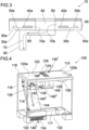
- a cooking hob 10 comprises two cooking regions 20a, 20b arranged on left-hand and right-hand sides of the cooking hob 10.
- the top view illustration of Fig. 2 shows the cooktop 60 in a transparent visualization in order to offer view onto two power boards 30a, 30b, each one thereof being associated with one of the two cooking regions 20a, 20b.
- each power board 30a, 30b includes a circuit with electronic components, including power electronics, which is not illustrated in Fig. 2 due to the schematic nature thereof.
- the power electronics of the two power boards 30a, 30b are positioned on or attached to heat sinks 40a, 40b for heat absorption from the power electronic components.
- cooling air is guided alongside the heat sinks 40a, 40b by means of associated cooling fans 50a, 50b for a further increase of the cooling effect on the electronic system.
- the exhaust air of the cooling process is guided away from the power board area and led to collection chamber 80, as indicated by arrows 70a, 70b.
- the exhaust system for the exhaust air 70a, 70b is generally visible in Fig. 3 being a schematic cross-sectional view of the cooking hob 10 as indicated by III - III in the illustrative view according to Fig. 2 .
- the individual exhaust air portions 70a, 70b leaving the related areas of power boards 30a, 30b are collected to form one single exhaust airstream 70 within the collection chamber 80, from where the exhaust airstream 70 is forwarded to an exhaust channel 90, which is arranged in a vertical orientation downwards from a bottom side of the cooking hob 10 in the area below the left-hand side cooking region 20a.
- the exhaust channel 90 is connected with the open base of the collection chamber 80 by a horizontal duct connection 90', so that the exhaust airstream 70 at first takes an S-shaped course.
- the exhaust air 70 leaves the exhaust channel 90 at an outlet opening at an end section, where it is blown out to ambient air.
- the exhaust channel 90 and an outlet opening may be designed similarly to the embodiment according to Fig. 4 , which is described in more detail further down below.
- the cooking hob of Figs 2 and 3 further includes two cooling air inlets 95a, 95b arranged in a bottom wall of the cooking hob casing 65 close to the suction openings of the cooling fans 50a, 50b.
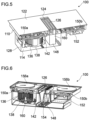
- Fig. 4 illustrates a combination appliance 100 comprising a cooking hob 110 and a downdraft extraction device 114 installed in a kitchen cabinet 116.
- the cooking hob 110 is installed in a cutout of a kitchen countertop 118 forming a top cover plate of the kitchen cabinet 116.
- the downdraft extraction device 114 is configured to take away cooking vapours occurring during cooking processes, in particular when cooking with uncovered cookware.
- the cooking hob 112 comprises cooking regions 120a, 120b arranged on a left half and a right half of a cooktop 122 of the cooking hob 110, which left and right halves are separated from each other by a suction opening 124 for an intake of the cooking vapours, the suction opening 124 being arranged alongside a cooktop centreline.
- the suction opening 124 is covered by a cover grid 126 for preventing items, e. g. cookware, to fall into the suction opening 124.
- a casing 128 of the extraction device 114 is shown in Fig. 4 in transparent illustration.
- Said casing 128 provides a closed outer shell or first channel for a flow of the sucked-in air including the cooking vapours on their way from the suction opening 124 to an exhaust opening 130 in a base area 132 of the kitchen cabinet 116 below a base wall 117 of the kitchen cabinet 116.
- Said exhaust opening 130 is also covered, specifically by an outlet grille 134.
- the flow of the sucked-in air through the extraction device 114 is driven by the operation of an extraction fan 136 arranged inside of the casing 128.
- Said extraction fan 136 comprises a bottom-sided intake opening 138 for sucking the conveyed air from the interior space of the casing 128.
- the conveyed air exits the extraction fan 136 at an outlet (not shown) at the fan rear side, which outlet is connected to a first end of an air duct 144 designed as a rectangular tube.
- the air duct 144 forms a second channel arranged downstream the above-mentioned first channel.
- an air duct bending by 90 degrees is implemented, which redirects the air flow from horizontal to vertical downwards.
- the air duct 144 may be guided alongside a rear side of the kitchen cabinet 116 and may be bent again by 90 degrees close to a rear lower edge of the kitchen cabinet 116 in order to direct the airflow towards exhaust opening 130 in the base area 132 of the kitchen cabinet 116.
- the second end of the air duct 144 is connected to the exhaust opening 130.
- the embodiment illustrated in Fig. 4 shows a solution of the air duct 144 with an inclined section of its downwardly directed portion, directed slightly to the right. Naturally, a solution with said portion arranged in an exact vertical direction is considerable as well.
- the course of the cooking vapours from the cooking area through the extraction device 114 to a re-entry into room air is illustrated in Fig. 4 by dotted arrows 146 1 to 146 5 .
- the cooking vapours pass through a filter device 148, which is arranged downstream directly behind the suction opening 124.
- Said filter device 148 is adapted to filter particles and droplets, in particular grease particles and droplets as well as moisture and odorous substances, out of the cooking vapours, in that purifying the cooking vapours in order to feed filtered air back to the room air.
- the cross-sectional view of Fig. 5 further shows two power boards 150a, 150b, one for the left cooking region 120a and one for the right cooking region 120b, the power boards 150a, 150b providing cooking zones in the left and right cooking regions 120a, 120b with electrical power.
- the cooking hob 110 is an induction cooking hob and the cooking zones are defined by induction coils 156a, 156b that are arranged below the cooktop 122 of the cooking hob 110.
- a further circuit board is arranged forming a control electronics 152 for the combination appliance 100.
- the extraction fan 136 comprises a cylindrical fan propeller with a plurality of fan blades arranged along a cylinder shell surface, the fan propeller rotating around a vertical axis 160.
- a central cross-section through the filter device 148 is also provided by Fig. 6 , which illustrates the arrangement of the filter 154 in the filter device 148.
- Fig. 7 shows an enlarged detail view similar to the cross-sectional presentation of the combination appliance 100 of Fig. 6 but in front view illustration. Contrary to the embodiment of Fig. 6 , the combination appliance 100 of Fig. 7 has a mirrored arrangement of the extraction device 114, i. e. the extraction fan 136 is positioned beneath the right-hand side cooking region 120b. As previously described, the extraction fan 136 is provided for extraction of cooking vapours from the top side of the cooktop 122. In addition, the extraction fan 136 may be also configured to produce the cooling airflows 170a, 170b, which are generated by the negative pressure occurring on the suction side of the extraction fan 136, i. e. in the interior of the common collection chamber 180.
- the extraction fan 136 may be also configured to produce the cooling airflows 170a, 170b, which are generated by the negative pressure occurring on the suction side of the extraction fan 136, i. e. in the interior of the common collection chamber 180.
- the common collection chamber 180 is connected to the area of the power boards 150a, 150b by passage openings 158a, 158b, which allow the cooling airflows 170a, 170b to pass through.
- the negative pressure generated by the extraction fan 136 takes effect directly at the passage openings 158a, 158b, so that it also takes effect onto the areas of the power boards 150a, 150b. Consequently, airstream is generated taking the path from the cooling air inlets 95a, 95b through the passage openings 158a, 158b towards the intake opening 138 of the extraction fan 136, in that forming the cooling airflows 170a, 170b.
- the cooling airflows 170a, 170b may be supported or produced by cooling fans (not shown) provided and arranged in the same or a similar way as by cooling fans 50a, 50b of the embodiment according to Figs. 2 and 3 .
- Both each one the cooling fans and the extraction fan 136 are individually controllable, which means that they are separately operable with adjustable speeds and/or conveying capacities. Thanks to these properties, both each one of the cooling airflows 170a, 170b as well as airflow including cooking vapours are adjustable in that way that the volume of the cooling airflows 170a, 170b can be set to a most efficient and/or best performance value.
- Fig. 8 illustrates a modification of the combination appliance 100 according to Fig. 7 , which modification is schematically shown with removed filter device 148. Contrary to the embodiment of Fig. 7 , the arrangement of Fig. 8 provides a valve 185a, 185b at each passage opening 158a, 158b between the areas of the power boards 150a, 150b and the common collection chamber 180.
- the valves 185a, 185b are controllable by the control electronics 152, and according to the operational state of the cooking regions 120a, 120b, the valves are open, partly closed or fully closed, which may depend on the temperature in each area of the power boards 150a, 150b issued from number and level(s) of operated cooking zone(s).
- valve 185a, 185b may be closed and a cooling airflow may only be performed through the other valve 185a, 185b.
- This functionality and operation of the valves 185a, 185b may replace or support the previously described functionality and operation of the cooling fans and extraction fan 136 for the adjustment of intensity of the individual cooling airflows 170a, 170b.
- the combination appliance 100 includes a common collection chamber 180 receiving in addition the cooking air through the suction opening 124 and filtered by the filter device 148.
- the confluence of cooling airflows and sucked cooking air is conveyed by the extraction fan 136 and blown out from the combination appliance 100 through exhaust channel 90 and exhaust opening 130, thereby returned to the ambient air in the kitchen room.
Abstract
The present invention concerns a cooking hob (10, 110), which comprises a casing (65, 128), a heating system for at least one cooking zone (20a, 20b, 120a, 120b), and a cooling system for heat dissipation from at least a part and/or at least one component of the heating system. At least a part of the cooling system is arranged in the casing (65, 128) and the cooling system comprises means for providing a flow of cooling air. Said means include at least one first inlet opening (95a, 95b) for an inlet of first inlet air, air transportation and/or air guiding means (50a, 50b, 136), and at least one first outlet opening (130) for an outlet of first exhaust air. According to a first aspect of the invention, the cooking hob (10, 110) is configured to let out the first exhaust air through the first outlet opening (130) into a first space or chamber and to take in the first inlet air through the first inlet opening (95a, 95b) from a second space or chamber. The second space or chamber is separated from the first space or chamber. According to a second, alternative aspect, the cooking hob (10, 110) is designed such that it includes at least one of
- the first inlet opening (95a, 95b) and the first outlet opening (130) are arranged at a distance from each other, which distance is particularly at least 15 cm;
- the blow-out direction of the first exhaust air is oriented away from the first inlet opening (95a, 95b);
- a partition wall is arranged between the first inlet opening (95a, 95b) and the first outlet opening (130);
- the cooking hob (10, 110) is configured to be installed in a kitchen furniture (116) and means are provided for an arrangement of the first outlet opening (130) in such a way that a partition wall (117) separates the first outlet opening (130) from the first inlet opening (95a, 95b);
- the cooking hob (10, 110) is configured to be mounted in an installation surface, the installation surface (118) forming a partition wall between the first inlet opening (95a, 95b) and the first outlet opening (130).
Further disclosed are a combination appliance (100) comprising a cooking hob (110) and an extraction device (114), as well as a method for controlling an airflow (70a, 70b, 170a, 170b) in a cooking hob (10, 110) or in a combination appliance (100).
Description
- The present invention relates to a cooking hob comprising a casing, at least one heating system and a cooling system, according to the preamble of claim 1. The present invention further relates to a combination appliance comprising a cooking hob and an extraction device according to claim 9. Finally, the present invention relates to a method for controlling an airflow in a cooking hob or in a combination appliance according to claims 13 and 14.
- During food preparation activities, specifically cooking of food on a cooking hob, for example on an induction cooking hob, not only the desired heating of cookware is performed, but also an unintended heating of components of the cooking hob or adjacent units or devices takes place. This effect is at least unfavourable and even may become dangerous in particular cases. In order to prevent such situations of overheating, generally a cooling system is implemented in such an appliance. However, the performance of the cooling system can be suboptimal, notably if said cooking hob is a built-in cooking hob. Such kind of underper-forming cooling system capacity results in a reduced performance efficiency of the cooking hob, particularly during an executed cooking process. Moreover, in order to avoid disturbances, e. g. in electronic systems, or even destructions of components due to overheating, a protective device or unit is implemented, which generally reduces the power of a heating unit compared to a user's selection. A typical reason for such kind of underperformance of the cooling system is the fact that the cooling air that is heated up during the cooling process by the components to be cooled and the heated air is returned to the cooling process due to the installation conditions, e. g. by sucking it back by means of a respective ventilation unit, so that the cooling capacity of the cooling air gradually decreases due to a reduction of its absorption capacity of thermal energy.
- Such kind of a cooking hob is particularly known from
EP 3 334 248 A1 -
EP 3 396 255 A1 - It is an object of the present invention to provide a cooking hob and/or a combination appliance with an improved heat dissipation for an enhanced cooling effect in order to increase the performance of the heating system. According to a further object, methods for supporting an improved cooling effect for the heating system both of the cooking hob and of the combination appliance shall be provided.
- The object is achieved for a cooking hob according to the preamble of claim 1 by the features of the characterizing part of claim 1.
- A cooking hob comprises a casing, a heating system for at least one cooking zone, and a cooling system for heat dissipation from at least a part and/or at least one component of the heating system. The cooking hob may be an induction cooking hob. The heating system particularly comprises at least one induction heating module and/or the at least one component may be a power electronic component. At least a part of the cooling system is arranged in the casing and the cooling system comprises means for providing a flow of cooling air. Said means include at least one first inlet opening for an inlet of first inlet air, air transportation and/or air guiding means, and at least one first outlet opening for an outlet of first exhaust air. According to a first aspect of the present invention, the cooking hob, in particular the cooling system of the cooking hob, is configured to let out, particularly to blow out, the first exhaust air through the first outlet opening into a first space or chamber and to take in the first inlet air through the first inlet opening from a second space or chamber. The invention further provides that the second space or chamber is separated from the first space or chamber. In particular, the second space or chamber is the interior of a building or a room and the first chamber is the exterior of the building or the room. According to a second aspect, which constitutes an alternative solution to the first aspect above, the cooking hob is designed such that at least one of the following is applicable:
- the first inlet opening and the first outlet opening are arranged or arrangeable at a distance from each other. Said distance is particularly at least 15 cm, more particularly at least 30 cm, even more particularly at least 50 cm;
- the blow-out direction of the first exhaust air goes away from the first inlet opening. The orientation of the exhaust air may be in an at least approximately opposite direction to the flow direction of the first inlet air;
- a partition wall is arranged between the first inlet opening and the first outlet opening;
- the cooking hob is configured to be installed in a kitchen furniture and the cooking hob comprises means for an arrangement of the first outlet opening such that, in the mounting position of the cooking hob, a partition wall separates the first outlet opening from the first inlet opening, the partition wall in particular being a bottom wall of the kitchen furniture;
- the cooking hob is configured to be mounted in an installation surface, which forms a partition wall between the first inlet opening and the first outlet opening. The installation surface may be a worktop of a kitchen furniture.
- More specifically, the kitchen furniture is a kitchenette or a kitchen cabinet. Moreover, the casing may be a single casing or housing including or configured to include the entire heating system, particularly being applicable also for the case of a heating system that has a modular structure and comprises a plurality of heating modules. Alternatively, the casing may be understood as a plurality of separate casings, more specifically comprising at least one individual casing for any kind of module in such a modular structure. In said situation of a plurality of casings, particularly if each heating module has its own casing, a plurality of first inlet openings may be provided as well, notably a specific first inlet opening may be allocated to each heating module.
- The object is further achieved for a cooking hob according to a third aspect of the invention, which may be an alternative solution for a cooking hob according to the present invention or it may be a specific embodiment of the cooking hob as previously described with reference to claim 1.
- A cooking hob comprises a casing, a heating system for at least one cooking zone, and a cooling system for heat dissipation from at least a part and/or at least one component of the heating system. The cooking hob may be an induction cooking hob. The heating system particularly comprises at least one induction heating module and/or the at least one component may be a power electronic component. At least a part of the cooling system is arranged in the casing and the cooling system comprises means for providing a flow of cooling air. Said means include at least one first inlet opening for an inlet of first inlet air, air transportation and/or air guiding means, and at least one first outlet opening for an outlet of first exhaust air. According to the third aspect of the invention, the cooking hob is configured for an installation in an installation surface and is designed in such a way that the installed cooking hob provides an intake of first inlet air through a first inlet opening arranged or arrangeable on a top side of the installation surface and an outlet, which may be a blowing out, of first exhaust air through a first outlet opening arranged or arrangeable below a bottom side of the installation surface. A specific embodiment for the installation surface is a worktop of a kitchen furniture.
- One particular embodiment, more specifically defining the cooking hob according to anyone of the first, second or third aspects, is characterized in that the first outlet opening is arranged at an end section of a channel. As a result, by means of said channel, the first outlet opening is arrangeable distant from the first inlet opening, so that the exhaust air is blown out in sufficient distance so as not to be returned to the cooling process. In particular, at least a section of the channel, more specifically at least the end section of the channel, is arranged or arrangeable in a bottom area of a kitchen furniture. Said bottom area is preferably a plinth area.
- The object is further achieved for a cooking hob according to a fourth aspect of the invention, which may be an alternative solution for a cooking hob according to the present invention or it may be specific embodiment of the cooking hob as previously described with reference to claim 1.
- A cooking hob comprises a casing, a heating system for at least one cooking zone, and a cooling system for heat dissipation from at least a part and/or at least one component of the heating system. The cooking hob may be an induction cooking hob. The heating system particularly comprises at least one induction heating module and/or the at least one component may be a power electronic component. At least a part of the cooling system is arranged in the casing and the cooling system comprises means for providing a flow of cooling air. Said means include at least one first inlet opening for an inlet of first inlet air, air transportation and/or air guiding means, and at least one first outlet opening for an outlet of first exhaust air. According to the fourth aspect of the invention, a channel is provided to spatially separate first intake opening and first outlet opening from one another. More specifically, the channel ensures that the first inlet opening and the first outlet opening are arranged at a distance from each other. Said distance is particularly at least 15 cm, more particularly at least 30 cm, even more particularly at least 50 cm.
- More specifically, the first outlet opening is arranged at an end section of the channel, wherein particularly at least a section of the channel, more particularly at least the end section, is arranged or arrangeable in a bottom area, preferably in a plinth area, of a kitchen furniture, in which the cooking hob is mountable or mounted. Accordingly, the first outlet opening is arrangeable in such a distance to the first inlet opening that advantageously an air return is excluded at least to a great extent. In order to have the first outlet opening, which is specifically arranged at the channel end section, separated from the first inlet opening by a partition wall, e. g. the bottom wall of the kitchen furniture, the channel is preferably led through an opening in said partition wall.
- In the following, specific embodiments of at least one of the previously presented general solutions of the cooking hob according to one of the four aspects of the present invention are described.
- The cooking hob may comprise a heating system, which includes at least a first and a second heating unit. Said first and second heating units may be first and second induction heating modules. The cooling system is configured to act on at least a part and/or at least one component of each of the at least first and second heating units. More specifically, said at least one component is a power electronic component. Further, the cooling system is configured to provide the first heating unit with a first cooling airflow and the second heating unit with a second cooling airflow. Moreover, a collection space or chamber is provided for receiving the first and second cooling airflows, which collection space or chamber is preferably arranged upstream of the first outlet opening. More specifically, the collection space or chamber may be arranged upstream of the channel.
- In some implementations, the air transportation means is arranged downstream of the heating system. Said air transportation means particularly comprises at least one first air blower. The air transportation means may be arranged in the collection space or chamber or downstream thereof. The air transportation means may also be positioned at or close to the first outlet opening. On the other hand, an arrangement upstream of the channel may be favourable. It is to be noted that in this setup the conveyance of the cooling air is caused by means of a suction effect as a result of negative pressure that occurs on the suction side of a ventilation unit, particularly of the first air blower.
- According to embodiments, the collection space or chamber comprises at least one passage opening for receiving the first and second cooling airflows. In order to provide an efficient cooling for the at least first and second heating units, preferably at least one passage opening for each one of the first and second airflows is considered. In particular, at least one of the at least one passage opening is closable by a closing means or a cross-sectional area of the at least one passage opening is reduceable providing a reduced air throughput. For example, such reduction of cooling airflow performed for a first one of the first and second heating units may result in an increased air transportation effect for the other heating unit, i. e. the second one of the first and second heating units. Said closing means is specifically a valve or a flap, which may be operable by any type of driving means, e. g. an actuating motor, a wax motor, or the like.
- Another specific embodiment is characterized by an air transportation means, which is arranged upstream of the collection space or chamber. Some particular implementations are characterized by a heating system, which comprises at least one air blower. In the preferred embodiment of the heating system comprising first and second heating units, each one thereof may be provided with an air blower. In particular, at least one air blower is assigned to or arranged in each one of the at least first and second heating units. This type of air blower related to the heating system, specifically to the first and second heating units, may be a second air blower.
- The cooking hob may be configured to be mounted in an installation surface such that the first inlet opening is arranged below a bottom side of the installation surface. An arrangement of the first inlet opening on a side wall or a bottom wall of the casing is a preferred solution. That way, any spillage of liquid on a top side of the installation surface will not be able to enter the interior of the heating system. More specifically, each one of a plurality of heating units having its own casing may include an allocated first inlet opening.
- An alternative solution for the cooking hob according to the present invention is characterized in that an at least one first inlet opening is provided, which is arranged at a lateral and/or rear and/or front side of the cooking hob. The first inlet opening is preferably positioned in such a way as to be arranged or arrangeable above an installation surface for the cooking hob, which installation surface may be a worktop particularly of a kitchenette or a kitchen cabinet. The first inlet opening may have an orientation in a way that the direction of the intake of the first inlet air is at least approximately parallel to the installation surface and/or to the cooktop of the cooking hob. Due to the positioning above the installation surface, a protection means for avoiding spillage of liquid to enter the at least one first inlet opening may be considered, e. g. any kind of liquid discharge trap.
- The object is further achieved for a combination appliance according to the preamble of claim 9 by the features of the characterizing part of claim 9.
- According to yet another aspect of the invention, a combination appliance is provided, which comprises a cooking hob according to anyone of the previously described embodiments and an extraction device. The extraction device comprises a second inlet opening for taking in second inlet air and a second outlet opening for blowing out second exhaust air. The second inlet air particularly comprises cooking fumes generated during a cooking process, which can be performed on the cooking hob. The second inlet opening is preferably positioned on a cooktop of the cooking hob, wherein a central positioning may be considered. The combination appliance, more specifically the extraction device, preferably further comprises a separation and/or filtering device for filtration and/or separation of particles and/or odours from the conveyed air. The separation and/or filtering device may be positioned downstream, preferably directly downstream, of the second inlet opening of the extraction device.
- A preferred solution for the combination appliance is characterized in that the first and second outlet openings form a common outlet opening. This solution may avoid a provision of a plurality of components or devices, so that costs may be kept down.
- According to embodiments, a common collection space or chamber is provided, which is configured for receiving the cooling air, in particular the first and second cooling airflows, and the second inlet air, particularly the air comprising cooking fumes. The common collection space or chamber is preferably arranged upstream of the first outlet opening and/or the second outlet opening.
- One specific solution for the combination appliance according to the present invention is characterized in that the combination appliance is configured to be mounted in an installation surface such that the first and second inlet openings are arranged or arrangeable above the installation surface of the combination appliance and/or above a cooktop of the cooking hob. The first inlet opening is configured or designed to take in the first inlet air in a direction towards a central zone of the cooktop, wherein the first inlet air preferably flows through the first inlet opening in a horizontal direction. Moreover, the second inlet opening is configured or designed to take in the second inlet air in an at least approximately top-down direction.
- Advantageously, the common collection space or chamber comprises at least one passage opening for receiving the first and second cooling airflows, which at least one passage opening opens into the common collection space or chamber by establishing an airflow oriented in downward direction. Preferably, at least one passage opening is provided for each one of the first and second airflows. Such passage opening, which is directed downwards, avoids hot fumes to enter the area of the heating system, even in the case when no air transportation means is operated. A more advanced embodiment, however, is formed by at least one passage opening, which comprises a closing means, or cross-sectional area reducing means, respectively, which may provide an even more effective avoidance of cooking fumes entering a heating system area. A valve or a flap may be one option for such kind of closing means.
- On the other hand, another control of the ratio between the volumes of first inlet air and second inlet air may be achieved by providing means for a reduction of the cross-sectional area or for a closure of the second inlet opening. That way, a reduced intake of an air comprising cooking fumes sucked in through the second inlet opening may cause a booster effect for the cooling of the heating system.
- Moreover, sensor means for a control of the temperature inside the heating system, particularly of the power electronic components, may be considered. The state of the closing means or the means for controlling a cross-sectional area related to the passage opening and/or to the second inlet opening may be controllable dependent on the measured temperature, particularly of the power electronic components.
- In some implementations, a further measure for receiving an increased cooling effect is provided by an arrangement of cooling means, specifically of at least one heat sink unit, attached to the channel wall or to the wall of the common collection space or chamber. This specific measure results in thermal conduction through this wall for a further increased heat dissipation, supporting the cooling effect performed by the cooling airflow.
- According to one embodiment, the cooling air is guided to pass through the filter device of the extraction device in order to filter the cooling airflow. In particular, the cooling air passes an odour and/or VOC filter device, which may be favourable for receiving a pleasant room atmosphere.
- The object is achieved for a method for operating a cooking hob according to the preamble of claim 13 by the features of the characterizing part of claim 13.
- According to yet another aspect of the present invention, a method for operating a cooking hob, in particular the cooking hob according to anyone of the herein disclosed cooking hob embodiments, is provided. The method is related to a cooking hob, which comprises a heating system with at least a first heating unit and a second heating unit for at least two cooking zones and a cooling system for heat dissipation from at least a part and/or at least one component, particularly a power electronic component, of each one of the first and the second heating units. Said first and second heating units may be at least a first induction heating module and a second induction heating module. A first cooling airflow is driven over the at least a part and/or at least one component of the first heating unit and a second cooling airflow is driven over the at least a part and/or at least one component of the second heating unit towards at least one outlet opening. According to the invention, the first cooling airflow enters a collection space or chamber through a first passage opening and the second cooling airflow enters the collection space or chamber through a second passage opening. Said collection space or chamber is configured for receiving, and it receives, said first and second cooling airflows. Moreover, at least one cooling control means controls the first cooling airflow and/or the second cooling airflow
- by controlling the cross-sectional area of the first passage opening and/or the cross-sectional area of the second passage opening;
and/or - by controlling the conveying capacity of a first air transportation means of the first heating unit and/or the conveying capacity of a second air transportation means of the second heating unit.
- By taking at least one of said measures related to the first and/or second passage openings, additionally or alternatively related to the first and/or second air transportation means, at least one of the first and second airflows may be adjustable in its intensity and any reduction of one airflow may result in a booster effect for the other airflow. This may result in an adjusted cooling intensity depending on the different heating power values provided to the different heating units and/or cooking zones.
- Finally, the object is achieved for a method for operating a combination appliance according to the preamble of claim 14 by the features of the characterizing part of claim 14.
- According to yet another aspect of the present invention, a method for operating a combination appliance, in particular the combination appliance according to anyone of the herein disclosed combination appliance embodiments, is provided. The method relates to a combination appliance comprising a heating system with at least one heating unit, in particular at least one induction heating module, for at least one cooking zone and further comprising a cooling system for heat dissipation from at least a part and/or at least one component, particularly a power electronic component, of the heating system. A cooling airflow is driven over the at least a part and/or at least one component of the heating system towards at least one first outlet opening. Moreover, an airflow comprising cooking fumes is conveyed through an extraction device of the combination appliance by means of an extraction device air transportation means from an inlet opening to at least one second outlet opening. According to the invention, a common collection space or chamber receives the cooling airflow and the airflow comprising cooking fumes. The cooling airflow enters the common collection space or chamber through a passage opening, and the airflow comprising cooking fumes enters the common collection space or chamber through a second inlet opening, e. g. a suction opening, which is preferably an exhaust inlet opening or cooking fumes inlet opening, arranged in a cooktop of the cooking hob. At least one cooling control means controls the cooling airflow and/or the airflow comprising cooking fumes by controlling the cross-sectional area of the passage opening and/or the cross-sectional area of the suction opening. Additionally, or alternatively, the at least one cooling control means controls the cooling airflow and/or the airflow comprising cooking fumes by controlling the conveying capacity of the extraction device air transportation means and/or the conveying capacity of a cooling air transportation means arranged in or allocated to, in particular solely allocate to, the heating system.
- The method related to the combination appliance may be further characterized in that the cooling air transportation means is at least operated, in particular with a high conveying capacity, when the extraction device air transportation means is not operated or operated with only a low conveying capacity. Additionally, or alternatively, the method may make provisions for the cooling air transportation means being operated with only a low conveying capacity or not being operated, when or while the extraction device air transportation means is operated with at least a medium conveying capacity.
- By taking at least one of said measures related to the at least one passage opening and the second inlet opening, additionally or alternatively related to the extraction device air transportation means and/or the cooling air transportation means, at least one of the related airflows may be adjustable in its intensity and any reduction of one airflow may result in a booster effect for the other airflow. This may not only be related to the airflow ratio between cooling airflow and cooking fumes airflow, but also between differently operated first and second heating zones and related first and second heating units, if the heating system of the combination appliance comprises at least a first and a second heating unit with respectively allocated first and/or second passage openings towards the common collection space or chamber.
- Anyone of the methods related to the cooking hob or to the combination appliance may provide for an alternating and/or a temporary closure or cross-sectional area manipulation of any passage opening or openings. The same may apply for any kind of control of any air transportation means, which, again, may be performed alternatively or in combination with the passage opening control.
- Afore-mentioned control operations are preferably supported by at least one sensor, which is included in the cooking hob or the combination appliance. The sensor, which may be or may include a sensor, for example a temperature sensor, may provide information for the respective cooling control means, so that depending on the current operational mode of the combination appliance, and particularly the number and distribution of operated cooking zones, best possible performance for both cooling effect and cooking fumes extraction effect is configurable.
- With respect to a specific example of a combination appliance, which has at least a first heating unit that is cooled by a first cooling airflow, and a second heating unit that is cooled by a second cooling airflow, closing means or cross-sectional area reducing means and/or related cooling air transportation means may be activated or operated in such way that only this specific heating unit is cooled by a cooling airflow, which is currently driving or operating a cooking zone.
- Novel and inventive features of the present invention are set forth in the appended claims.
- The present invention will be described in further detail with reference to the drawings, in which
- Fig. 1
- is a schematic cross-sectional view of an induction heating unit for an induction cooking hob according to a prior art solution;
- Fig. 2
- is a schematic illustration of an induction cooking hob according to a first embodiment of the present invention including two induction boards in top view;
- Fig. 3
- is a schematic cross-sectional view indicated by III - III in the illustrative view according to
Fig. 2 ; - Fig. 4
- is a perspective view of a combination appliance comprising a cooking hob and an extraction device, illustrating a second embodiment of the present invention, installed in a kitchen cabinet;
- Fig. 5
- is a cross-sectional perspective view of the disassembled combination appliance of
Fig. 4 with frontal surface cut away; - Fig. 6
- is a combination appliance slightly different from that one of
Fig. 5 with transparent cooktop in a central cross-sectional view and shown from another perspective; - Fig. 7
- is a section of a cross-sectional side view of a combination appliance similar to
Fig. 6 , but with mirrored arrangement of the extraction device; and - Fig. 8
- illustrates a modification of the combination appliance according to
Fig. 7 , but additionally with a filter unit left away. -
Fig. 1 illustrates a cross-sectional view of aninduction heating unit 2 of an induction cooking hob 1, which is known from the prior art. Theinduction heating unit 2 comprises apower board 3 for supplying an induction coil (not shown inFig. 1 ) with electrical energy, thereby defining a cooking zone of the induction cooking hob 1. Thepower board 3 comprises a circuit with electronic components, including power electronics, which is not illustrated inFig. 1 due to its schematic nature. Said power electronics are heated up during their operation and need to be cooled down in order not to lose performance or even to avoid their damage. To this end, the power electronic components, specifically fast power switching components such as IG-BTs, are positioned on or attached to aheat sink 4, which is adapted for heat absorption. In order to further increase the cooling effect on the electronic system, cooling air is guided alongside theheat sink 4 by means of a cooling fan 5. Theinduction heating unit 2 is included in ahousing 7, which is covered on its top side by acooktop 6, usually a glass ceramics cooktop, which forms a cooking surface for placing cookware for a cooking process thereon. Byarrows 8, 8' circulation of cooling air is indicated, which is generated by the cooling fan 5 blowing the conveyed air towards theheat sink 4.Arrow 8 illustrates that, due to a substantially closed system formed byhousing 7 and coveringcooktop 6, only a portion of the conveyed cooling air is taken from an unheated space, while according to arrow 8' another portion is formed by a recirculated airflow returning from the air convection process and having been heated up already during cooling down theheat sink 4. It is readily understood that the cooling capacity of a warmed airflow is reduced and the longer the cooling process, the lower the cooling capacity due to a constantly increasing temperature of the conveyed cooling air. - In order to avoid the afore-described recirculation of cooling air and a resulting heating up of cooling air, the exhaust air of the cooling process is taken away from the area from which the cooling fan takes in the air to be conveyed. This will be described in detail with reference to the schematic illustrations of
Fig. 2 andFig. 3 . As can be seen inFig. 2 , acooking hob 10 comprises twocooking regions cooking hob 10. The top view illustration ofFig. 2 shows thecooktop 60 in a transparent visualization in order to offer view onto twopower boards cooking regions Fig. 1 , eachpower board Fig. 2 due to the schematic nature thereof. The power electronics of the twopower boards heat sinks heat sinks fans Fig. 1 , the exhaust air of the cooling process is guided away from the power board area and led tocollection chamber 80, as indicated byarrows - The exhaust system for the
exhaust air Fig. 3 being a schematic cross-sectional view of thecooking hob 10 as indicated by III - III in the illustrative view according toFig. 2 . The individualexhaust air portions power boards single exhaust airstream 70 within thecollection chamber 80, from where theexhaust airstream 70 is forwarded to anexhaust channel 90, which is arranged in a vertical orientation downwards from a bottom side of thecooking hob 10 in the area below the left-handside cooking region 20a. Theexhaust channel 90 is connected with the open base of thecollection chamber 80 by a horizontal duct connection 90', so that theexhaust airstream 70 at first takes an S-shaped course. As not shown inFig. 3 , theexhaust air 70 leaves theexhaust channel 90 at an outlet opening at an end section, where it is blown out to ambient air. In a somehow different arrangement, theexhaust channel 90 and an outlet opening may be designed similarly to the embodiment according toFig. 4 , which is described in more detail further down below. The cooking hob ofFigs 2 and3 further includes two coolingair inlets cooking hob casing 65 close to the suction openings of the coolingfans - The previously described
cooking hob 10 forms a first general example of a cooking appliance with a combined exhaust air outlet. In the following, a second general example with a combined exhaust air outlet is presented.Fig. 4 illustrates acombination appliance 100 comprising acooking hob 110 and adowndraft extraction device 114 installed in akitchen cabinet 116. Thecooking hob 110 is installed in a cutout of akitchen countertop 118 forming a top cover plate of thekitchen cabinet 116. Thedowndraft extraction device 114 is configured to take away cooking vapours occurring during cooking processes, in particular when cooking with uncovered cookware. The cooking hob 112 comprisescooking regions cooktop 122 of thecooking hob 110, which left and right halves are separated from each other by asuction opening 124 for an intake of the cooking vapours, thesuction opening 124 being arranged alongside a cooktop centreline. Thesuction opening 124 is covered by acover grid 126 for preventing items, e. g. cookware, to fall into thesuction opening 124. - A
casing 128 of theextraction device 114 is shown inFig. 4 in transparent illustration. Said casing 128 provides a closed outer shell or first channel for a flow of the sucked-in air including the cooking vapours on their way from thesuction opening 124 to anexhaust opening 130 in abase area 132 of thekitchen cabinet 116 below abase wall 117 of thekitchen cabinet 116. Saidexhaust opening 130 is also covered, specifically by anoutlet grille 134. - The flow of the sucked-in air through the
extraction device 114 is driven by the operation of anextraction fan 136 arranged inside of thecasing 128. Saidextraction fan 136 comprises a bottom-sided intake opening 138 for sucking the conveyed air from the interior space of thecasing 128. - The conveyed air exits the
extraction fan 136 at an outlet (not shown) at the fan rear side, which outlet is connected to a first end of anair duct 144 designed as a rectangular tube. Theair duct 144 forms a second channel arranged downstream the above-mentioned first channel. Directly at the passage from the fan outlet to theair duct 144, an air duct bending by 90 degrees is implemented, which redirects the air flow from horizontal to vertical downwards. Theair duct 144 may be guided alongside a rear side of thekitchen cabinet 116 and may be bent again by 90 degrees close to a rear lower edge of thekitchen cabinet 116 in order to direct the airflow towards exhaust opening 130 in thebase area 132 of thekitchen cabinet 116. Accordingly, the second end of theair duct 144 is connected to theexhaust opening 130. The embodiment illustrated inFig. 4 shows a solution of theair duct 144 with an inclined section of its downwardly directed portion, directed slightly to the right. Naturally, a solution with said portion arranged in an exact vertical direction is considerable as well. - The course of the cooking vapours from the cooking area through the
extraction device 114 to a re-entry into room air is illustrated inFig. 4 by dottedarrows 1461 to 1465. On their way through theextraction device 114, the cooking vapours pass through afilter device 148, which is arranged downstream directly behind thesuction opening 124. Saidfilter device 148 is adapted to filter particles and droplets, in particular grease particles and droplets as well as moisture and odorous substances, out of the cooking vapours, in that purifying the cooking vapours in order to feed filtered air back to the room air. - The cross-sectional view of
Fig. 5 further shows twopower boards left cooking region 120a and one for theright cooking region 120b, thepower boards right cooking regions cooking hob 110 is an induction cooking hob and the cooking zones are defined byinduction coils cooktop 122 of thecooking hob 110. Attached to the bottom side of thepower board 150b assigned to theright cooking region 120b, a further circuit board is arranged forming acontrol electronics 152 for thecombination appliance 100. - As can be seen in
Fig. 6 , which is also a cross-sectional illustration of thecombination appliance 100, but with a section plane in a centre region (lengthwise related to the rectangular design of the cooking hob 110), theextraction fan 136 comprises a cylindrical fan propeller with a plurality of fan blades arranged along a cylinder shell surface, the fan propeller rotating around avertical axis 160. Further, a central cross-section through thefilter device 148 is also provided byFig. 6 , which illustrates the arrangement of thefilter 154 in thefilter device 148. -
Fig. 7 shows an enlarged detail view similar to the cross-sectional presentation of thecombination appliance 100 ofFig. 6 but in front view illustration. Contrary to the embodiment ofFig. 6 , thecombination appliance 100 ofFig. 7 has a mirrored arrangement of theextraction device 114, i. e. theextraction fan 136 is positioned beneath the right-handside cooking region 120b. As previously described, theextraction fan 136 is provided for extraction of cooking vapours from the top side of thecooktop 122. In addition, theextraction fan 136 may be also configured to produce thecooling airflows extraction fan 136, i. e. in the interior of thecommon collection chamber 180. Thecommon collection chamber 180 is connected to the area of thepower boards passage openings cooling airflows extraction fan 136 takes effect directly at thepassage openings power boards air inlets passage openings intake opening 138 of theextraction fan 136, in that forming thecooling airflows cooling airflows fans Figs. 2 and3 . Both each one the cooling fans and theextraction fan 136 are individually controllable, which means that they are separately operable with adjustable speeds and/or conveying capacities. Thanks to these properties, both each one of thecooling airflows cooling airflows -
Fig. 8 illustrates a modification of thecombination appliance 100 according toFig. 7 , which modification is schematically shown with removedfilter device 148. Contrary to the embodiment ofFig. 7 , the arrangement ofFig. 8 provides avalve passage opening power boards common collection chamber 180. Thevalves control electronics 152, and according to the operational state of thecooking regions power boards cooking regions related valve other valve valves extraction fan 136 for the adjustment of intensity of theindividual cooling airflows - It is to be noted that even though the designs of the first and the second examples are different, the functionality with respect a combined exhaust cooling air outlet is similar. Different to the
cooking hob 10 according toFigs. 2 and3 comprising acollection chamber 80 for receiving thecooling airflows common airflow 70, thecombination appliance 100 according toFigs. 4 to 8 includes acommon collection chamber 180 receiving in addition the cooking air through thesuction opening 124 and filtered by thefilter device 148. The confluence of cooling airflows and sucked cooking air is conveyed by theextraction fan 136 and blown out from thecombination appliance 100 throughexhaust channel 90 andexhaust opening 130, thereby returned to the ambient air in the kitchen room. - Although illustrative embodiments of the present invention have been described herein with reference to the accompanying drawings, it is to be understood that the present invention is not limited to these precise embodiments, and that various other changes and modifications may be affected therein by one skilled in the art without departing from the scope or spirit of the invention. All such changes and modifications are intended to be included within the scope of the invention as defined by the appended claims.
-
- 1,10
- cooking hob
- 2,20a,20b
- cooking zones/regions
- 3,30a,30b
- power boards
- 4,40a,40b
- heat sinks
- 5,50a,50b
- cooling fans
- 6,60
- cooktop
- 7,65
- housing
- 8,8',70,70a,70b
- airflows
- 80
- collection chamber
- 90
- exhaust channel
- 90'
- duct connection
- 95a,95b
- cooling air inlets
- 100
- combination appliance
- 110
- cooking hob
- 114
- downdraft extraction device
- 116
- kitchen cabinet
- 117
- base wall
- 118
- kitchen countertop
- 120a,120b
- cooking zones/regions
- 122
- cooktop
- 124
- suction opening
- 126
- cover grid
- 128
- casing
- 130
- exhaust opening
- 132
- base area
- 134
- outlet grille
- 136
- extraction fan
- 138
- intake opening
- 142
- fan housing
- 144
- air duct
- 1461 to 5
- arrows indicating air flow
- 148
- filter device
- 150a,150b
- power boards
- 152
- control electronics
- 154
- filter
- 156a,156b
- induction coils
- 158a,158b
- passage openings
- 160
- vertical axis
- 170a,170b
- airflows
- 180
- common collection chamber
- 185a,185b
- valves
Claims (15)
- A cooking hob (10, 110), in particular an induction cooking hob, comprising- a casing (65, 128),- a heating system, in particular comprising at least one induction heating module (30a, 30b, 150a, 150b, 156a, 156b), for at least one cooking zone (20a, 20b, 120a, 120b), and- a cooling system for heat dissipation from at least a part and/or at least one component, particularly a power electronic component, of the heating system,wherein at least a part of the cooling system is arranged in the casing (65, 128) and wherein the cooling system comprises means for providing a flow of cooling air, which means include at least one first inlet opening (95a, 95b) for an inlet of first inlet air, air transportation and/or air guiding means (50a, 50b, 136), and at least one first outlet opening (130) for an outlet of first exhaust air,
characterized in thata. the cooking hob (10, 110), in particular the cooling system of the cooking hob (10, 110), is configured to let out the first exhaust air through the first outlet opening (130) into a first space or chamber and to take in the first inlet air through the first inlet opening (95a, 95b) from a second space or chamber, wherein the second space or chamber is separated from the first space or chamber, in particular the second space or chamber being the interior of a building or a room and the first chamber being the exterior of the building or the room,
or in thatb. the cooking hob (10, 110) is designed such that it includes at least one of- the first inlet opening (95a, 95b) and the first outlet opening (130) are arranged at a distance from each other, which distance is particularly at least 15 cm, more particularly at least 30 cm, even more particularly at least 50 cm;- the blow-out direction of the first exhaust air is oriented away from the first inlet opening (95a, 95b), in particular at least approximately in opposite direction to the flow direction of the first inlet air;- a partition wall is arranged between the first inlet opening (95a, 95b) and the first outlet opening (130);- the cooking hob (10, 110) is configured to be installed in a kitchen furniture (116) and means are provided for an arrangement of the first outlet opening (130) in such a way that a partition wall (117) separates the first outlet opening (130) from the first inlet opening (95a, 95b), the partition wall in particular being a bottom wall (117) of the kitchen furniture (116);- the cooking hob (10, 110) is configured to be mounted in an installation surface, preferably in a worktop (118) of a kitchen furniture (116), the installation surface (118) forming a partition wall between the first inlet opening (95a, 95b) and the first outlet opening (130). - The cooking hob (10, 110) according to claim 1,
characterized in that
the first outlet opening (130) is arranged at an end section of a channel (90, 144), wherein particularly at least a section of the channel (90, 144), more particularly at least the end section, is arranged or arrangeable in a bottom area (132), preferably in a plinth area, of a kitchen furniture (116) . - The cooking hob (10, 110) according to claim 1 or 2,
characterized in that
the heating system comprises at least a first and a second heating unit, in particular at least a first and a second induction heating module (30a, 30b, 150a, 150b, 156a, 156b),- wherein the cooling system is configured to act on at least a part and/or at least one component, particularly a power electronic component, of each of the at least first and second heating units (30a, 30b, 150a, 150b, 156a, 156b),- wherein the cooling system is configured to provide the first heating unit (30a, 150a, 156a) with a first cooling airflow (70a, 170a) and the second heating unit (30b, 150b, 156b) with a second cooling airflow (70b, 170b),- and wherein a collection space or chamber (80, 180) is provided for receiving the first and second cooling airflows (70a, 70b, 170a, 170b), which collection space or chamber (80, 180) is particularly arranged upstream of the first outlet opening (130), more particularly upstream of the channel (90, 144). - The cooking hob (10, 110) according to anyone of the preceding claims,
characterized in that
the air transportation means (50a, 50b, 136), in particular comprising at least one first air blower, is arranged downstream of the heating system, particularly in or downstream of the collection space or chamber (80, 180), more particularly upstream of the channel (90, 144). - The cooking hob (10, 110) according to claim 3 or 4, characterized in that
the collection space or chamber (80, 180) comprises at least one passage opening (158a, 158b) for receiving the first and second cooling airflows (70a, 70b, 170a, 170b), preferably at least one passage opening for each one of the first and second airflows (70a, 70b, 170a, 170b), in particular at least one of the at least one passage opening (158a, 158b) is closable by a closing means (185a, 185b), particularly a valve or a flap, or a cross-sectional area of the at least one passage opening (158a, 158b) is reduceable. - The cooking hob (10, 110) according to anyone of the preceding claims,
characterized in that
the heating system, preferably each one of the at least a first and a second heating unit of the heating system, comprises at least one air blower (50a, 50b), in particular at least one second air blower. - The cooking hob (10, 110) according to anyone of the preceding claims,
characterized in that
the cooking hob (10, 110) is configured to be mounted in an installation surface (118) such that the at least one first inlet opening (95a, 95b) is arranged below a bottom side of the installation surface (118), the first inlet opening (95a, 95b) preferably being arranged on a side wall or a bottom wall of the casing (65). - The cooking hob (10, 110) according to anyone of the claims 1 to 6,
characterized in that
the at least one first inlet opening is arranged at a lateral and/or rear and/or front side of the cooking hob (10, 110), preferably positioned in such a way as to be arranged or arrangeable above an installation surface (118) for the cooking hob (10, 110), wherein the direction of the intake of the first inlet air is particularly at least approximately parallel to the installation surface (118) and/or the cooktop (60, 122) of the cooking hob (10, 110). - A combination appliance (100) comprising a cooking hob (110) according to anyone of the preceding claims and an extraction device (114), the extraction device (114) comprising- a second inlet opening (124) for taking in second inlet air, the second inlet air particularly comprising cooking fumes, the second inlet opening (124) preferably being positioned, particularly centrally, on a cooktop (122) of the cooking hob (110),- a second outlet opening (130) for blowing out second exhaust air,- particularly a separation and/or filtering device (148), the separation and/or filtering device (148) in particular being positioned downstream, preferably directly downstream, of the second inlet opening (130) of the extraction device (114),the first and second outlet openings (130) preferably forming a common outlet opening (130).
- The combination appliance (100) according to claim 9, characterized by
a common collection space or chamber (180) for receiving the cooling air, in particular the first and second cooling airflows (70a, 70b, 170a, 170b), and the second inlet air, particularly the air comprising cooking fumes, wherein the common collection space or chamber (180) is preferably arranged upstream of the first outlet opening (130) and/or the second outlet opening (130). - The combination appliance (100) according to claim 9 or 10, characterized in that
the combination appliance (100) is configured to be mounted in an installation surface (118) such that the first and second inlet openings (124) are arranged or arrangeable above the installation surface (118) and/or above a cooktop (122) of the cooking hob (110), the first inlet opening being configured or designed to take in the first inlet air in a direction towards a central zone of the cooktop (122), preferably in a horizontal direction, and the second inlet opening (124) being configured or designed to take in the second inlet air in an at least approximately top-down direction. - The combination appliance (100) according to anyone of the claims 9 to 11,
characterized in that
the common collection space or chamber (180) comprises at least one passage opening (158a, 158b) for receiving the first and second cooling airflows (70a, 70b, 170a, 170b), preferably at least one passage opening (158a, 158b) for each one of the first and second airflows (70a, 70b, 170a, 170b), which at least one passage opening (158a, 158b) opens into the common collection space or chamber (180) by establishing an airflow oriented in downward direction. - A method for controlling an airflow in a cooking hob (10, 110), in particular in the cooking hob (10, 110) according to anyone of the claims 1 to 8, the cooking hob (10, 110) comprising a heating system with at least a first heating unit and a second heating unit, in particular at least a first induction heating module (30a, 150a, 156a) and a second induction heating module (30b, 150b, 156b), for at least two cooking zones (20a, 20b, 120a, 120b) and a cooling system for heat dissipation from at least a part and/or at least one component, particularly a power electronic component, of each one of the first and the second heating units, wherein- a first cooling airflow (70a, 170a) is driven over the at least a part and/or at least one component of the first heating unit and- a second cooling airflow (70b, 170b) is driven over the at least a part and/or at least one component of the second heating unittowards at least one outlet opening (130),
characterized in that
the first cooling airflow (70a, 170a) enters a collection space or chamber (80, 180) for first and second cooling airflows (70a, 70b, 170a, 170b) through a first passage opening (158a) and the second cooling airflow (70b, 170b) enters the collection space or chamber (80, 180) through a second passage opening (158b), wherein at least one cooling control means controls the first cooling airflow (70a, 170a) and/or the second cooling airflow (70b, 170b)- by controlling the cross-sectional area of the first passage opening (158a) and/or the cross-sectional area of the second passage opening (158b);
and/or- by controlling the conveying capacity of a first air transportation means (50a) of the first heating unit and/or the conveying capacity of a second air transportation means (50b) of the second heating unit. - A method for controlling an airflow in a combination appliance (100), in particular in the combination appliance according to anyone of the claims 9 to 12, the combination appliance (100) comprising a heating system with at least one heating unit, in particular at least one induction heating module (150a, 150b, 156a, 156b), for at least one cooking zone (120a, 120b) and a cooling system for heat dissipation from at least a part and/or at least one component, particularly a power electronic component, of the heating system,- wherein a cooling airflow (170a, 170b) is driven over the at least a part and/or at least one component of the heating system towards at least one first outlet opening (130),- and wherein an airflow comprising cooking fumes is conveyed through an extraction device (114) of the combination appliance (100) by means of an extraction device air transportation means (136) from an inlet opening (124), particularly a second inlet opening, to at least one second outlet opening (130),characterized in that
a common collection space or chamber (180) is provided for receiving the cooling airflow (170a, 170b) and the airflow comprising cooking fumes, wherein the cooling airflow (170a, 170b) enters the common collection space or chamber (180) through a passage opening (158a, 158b) and the airflow comprising cooking fumes enters the common collection space or chamber (180) through a suction opening (124) or second inlet opening, preferably an exhaust inlet opening arranged in a cooktop (122) of the cooking hob (110), wherein at least one cooling control means controls the cooling airflow (170a, 170b) and/or the airflow comprising cooking fumes- by controlling the cross-sectional area of the passage opening (158a, 158b) and/or the cross-sectional area of the second inlet opening or suction opening (124);
and/or- by controlling the conveying capacity of the extraction device air transportation means (136) and/or the conveying capacity of a cooling air transportation means (50a, 50b) arranged in the heating system. - The method according to claim 14,
characterized in that
the cooling air transportation means (50a, 50b) is at least operated, in particular with a high conveying capacity, when the extraction device air transportation means (136) is not operated or operated with only a low conveying capacity, and/or the cooling air transportation means (50a, 50b) is not operated or operated with only a low conveying capacity, when the extraction device air transportation means (136) is operated with at least a medium conveying capacity.
Priority Applications (1)
| Application Number | Priority Date | Filing Date | Title |
|---|---|---|---|
| EP21216160.8A EP4198401A1 (en) | 2021-12-20 | 2021-12-20 | Cooking hob and combination appliance comprising a cooking hob |
Applications Claiming Priority (1)
| Application Number | Priority Date | Filing Date | Title |
|---|---|---|---|
| EP21216160.8A EP4198401A1 (en) | 2021-12-20 | 2021-12-20 | Cooking hob and combination appliance comprising a cooking hob |
Publications (1)
| Publication Number | Publication Date |
|---|---|
| EP4198401A1 true EP4198401A1 (en) | 2023-06-21 |
Family
ID=78957911
Family Applications (1)
| Application Number | Title | Priority Date | Filing Date |
|---|---|---|---|
| EP21216160.8A Pending EP4198401A1 (en) | 2021-12-20 | 2021-12-20 | Cooking hob and combination appliance comprising a cooking hob |
Country Status (1)
| Country | Link |
|---|---|
| EP (1) | EP4198401A1 (en) |
Citations (8)
| Publication number | Priority date | Publication date | Assignee | Title |
|---|---|---|---|---|
| US4431892A (en) * | 1981-07-17 | 1984-02-14 | Jenn-Air Corporation | Ventilated modular cooktop cartridge |
| US4899028A (en) * | 1986-12-11 | 1990-02-06 | Matsushita Electric Industrial Co., Ltd. | Suction and exhaust system of a heat cooking apparatus |
| JP5202922B2 (en) * | 2007-10-11 | 2013-06-05 | パナソニック株式会社 | Built-in equipment |
| EP3267116A1 (en) * | 2016-07-04 | 2018-01-10 | BSH Hausgeräte GmbH | Hotplate device |
| EP3334248A1 (en) | 2016-12-12 | 2018-06-13 | Electrolux Appliances Aktiebolag | Induction cooking hob with cooling system |
| EP3396255A1 (en) | 2017-04-26 | 2018-10-31 | Electrolux Appliances Aktiebolag | Induction cooking hob with integrated down-draft hood |
| DE102017213582A1 (en) * | 2017-08-04 | 2019-02-07 | E.G.O. Elektro-Gerätebau GmbH | Fan device for an electrical appliance, electrical appliance and method for controlling the same |
| KR102213160B1 (en) * | 2019-07-30 | 2021-02-05 | (주)쿠첸 | Cooking apparatus including hood |
-
2021
- 2021-12-20 EP EP21216160.8A patent/EP4198401A1/en active Pending
Patent Citations (8)
| Publication number | Priority date | Publication date | Assignee | Title |
|---|---|---|---|---|
| US4431892A (en) * | 1981-07-17 | 1984-02-14 | Jenn-Air Corporation | Ventilated modular cooktop cartridge |
| US4899028A (en) * | 1986-12-11 | 1990-02-06 | Matsushita Electric Industrial Co., Ltd. | Suction and exhaust system of a heat cooking apparatus |
| JP5202922B2 (en) * | 2007-10-11 | 2013-06-05 | パナソニック株式会社 | Built-in equipment |
| EP3267116A1 (en) * | 2016-07-04 | 2018-01-10 | BSH Hausgeräte GmbH | Hotplate device |
| EP3334248A1 (en) | 2016-12-12 | 2018-06-13 | Electrolux Appliances Aktiebolag | Induction cooking hob with cooling system |
| EP3396255A1 (en) | 2017-04-26 | 2018-10-31 | Electrolux Appliances Aktiebolag | Induction cooking hob with integrated down-draft hood |
| DE102017213582A1 (en) * | 2017-08-04 | 2019-02-07 | E.G.O. Elektro-Gerätebau GmbH | Fan device for an electrical appliance, electrical appliance and method for controlling the same |
| KR102213160B1 (en) * | 2019-07-30 | 2021-02-05 | (주)쿠첸 | Cooking apparatus including hood |
Similar Documents
| Publication | Publication Date | Title |
|---|---|---|
| US4786774A (en) | Combination compact microwave oven and ventilator system | |
| US6643123B2 (en) | Switchgear cabinet with at least one cabinet door and a fan-assisted air circulation on an interior | |
| US5918589A (en) | Low moisture/closed door broil oven ventilation system | |
| US10900665B2 (en) | Combination appliance having a cooktop and steam extraction device | |
| US20120255539A1 (en) | Overhead ventilation system incorporating a downwardly configured rear supply plenum with upward configured directional outlet and including baffle plates and dampeners incorporated into the plenum for evenly distributing an inlet airflow through the plenum outlet | |
| US7193195B2 (en) | Wall mounted microwave oven having a top vent with filter system | |
| KR20090055329A (en) | A vent grill | |
| KR20130054722A (en) | Ventilation apparatus and ventilation system having the same | |
| CN1102219C (en) | Microwave oven | |
| EP2918917B1 (en) | Home cooking appliance | |
| US11313564B2 (en) | Home cooking appliance having an air channel | |
| GB2389895A (en) | Vent hood and exhaust system for a kitchen stove | |
| US20230280045A1 (en) | Combination appliance | |
| US10119706B2 (en) | Home cooking appliance having a rear exhaust louver | |
| CN113646588A (en) | Combination device with a hood device and a cooking hob | |
| US7019272B2 (en) | Wall mounted microwave oven having an exhaust ventilation system | |
| KR20130036415A (en) | Microwave oven having hood | |
| EP4198401A1 (en) | Cooking hob and combination appliance comprising a cooking hob | |
| KR20110012038U (en) | Apparatus for rangehood having subsidiary inhale hole in kitchen | |
| KR20190004684A (en) | Ventilation apparatus and ventilation system having the same | |
| US20080092874A1 (en) | Overhead ventilation system incorporating a downwardly configured rear supply plenum with upward configured and reverse bended directional outlet | |
| CN112944416A (en) | Cooking device | |
| US20230175702A1 (en) | Extractor apparatus, and kitchen arrangement having a hob and an extractor apparatus | |
| EP3684141B1 (en) | Cooking device | |
| US20090183728A1 (en) | Overhead ventilation system incorporating a downwardly configured rear supply plenum with upward configured directional outlet and including baffle plates and dampeners incorporated into the plenum for evenly distributing an inlet airflow through the plenum outlet |
Legal Events
| Date | Code | Title | Description |
|---|---|---|---|
| PUAI | Public reference made under article 153(3) epc to a published international application that has entered the european phase |
Free format text: ORIGINAL CODE: 0009012 |
|
| STAA | Information on the status of an ep patent application or granted ep patent |
Free format text: STATUS: THE APPLICATION HAS BEEN PUBLISHED |
|
| AK | Designated contracting states |
Kind code of ref document: A1 Designated state(s): AL AT BE BG CH CY CZ DE DK EE ES FI FR GB GR HR HU IE IS IT LI LT LU LV MC MK MT NL NO PL PT RO RS SE SI SK SM TR |