EP4286673A2 - Verfahren zur steuerung des deflagrationsverbrennungsprozesses in einer kolbenlosen brennkammer - Google Patents
Verfahren zur steuerung des deflagrationsverbrennungsprozesses in einer kolbenlosen brennkammer Download PDFInfo
- Publication number
- EP4286673A2 EP4286673A2 EP23203129.4A EP23203129A EP4286673A2 EP 4286673 A2 EP4286673 A2 EP 4286673A2 EP 23203129 A EP23203129 A EP 23203129A EP 4286673 A2 EP4286673 A2 EP 4286673A2
- Authority
- EP
- European Patent Office
- Prior art keywords
- combustion chamber
- combustor
- pistonless
- input
- air
- Prior art date
- Legal status (The legal status is an assumption and is not a legal conclusion. Google has not performed a legal analysis and makes no representation as to the accuracy of the status listed.)
- Pending
Links
Images


Classifications
-
- F—MECHANICAL ENGINEERING; LIGHTING; HEATING; WEAPONS; BLASTING
- F02—COMBUSTION ENGINES; HOT-GAS OR COMBUSTION-PRODUCT ENGINE PLANTS
- F02C—GAS-TURBINE PLANTS; AIR INTAKES FOR JET-PROPULSION PLANTS; CONTROLLING FUEL SUPPLY IN AIR-BREATHING JET-PROPULSION PLANTS
- F02C5/00—Gas-turbine plants characterised by the working fluid being generated by intermittent combustion
- F02C5/12—Gas-turbine plants characterised by the working fluid being generated by intermittent combustion the combustion chambers having inlet or outlet valves, e.g. Holzwarth gas-turbine plants
-
- F—MECHANICAL ENGINEERING; LIGHTING; HEATING; WEAPONS; BLASTING
- F23—COMBUSTION APPARATUS; COMBUSTION PROCESSES
- F23R—GENERATING COMBUSTION PRODUCTS OF HIGH PRESSURE OR HIGH VELOCITY, e.g. GAS-TURBINE COMBUSTION CHAMBERS
- F23R7/00—Intermittent or explosive combustion chambers
-
- F—MECHANICAL ENGINEERING; LIGHTING; HEATING; WEAPONS; BLASTING
- F23—COMBUSTION APPARATUS; COMBUSTION PROCESSES
- F23C—METHODS OR APPARATUS FOR COMBUSTION USING FLUID FUEL OR SOLID FUEL SUSPENDED IN A CARRIER GAS OR AIR
- F23C6/00—Combustion apparatus characterised by the combination of two or more combustion chambers or combustion zones, e.g. for staged combustion
- F23C6/04—Combustion apparatus characterised by the combination of two or more combustion chambers or combustion zones, e.g. for staged combustion in series connection
- F23C6/045—Combustion apparatus characterised by the combination of two or more combustion chambers or combustion zones, e.g. for staged combustion in series connection with staged combustion in a single enclosure
- F23C6/047—Combustion apparatus characterised by the combination of two or more combustion chambers or combustion zones, e.g. for staged combustion in series connection with staged combustion in a single enclosure with fuel supply in stages
-
- F—MECHANICAL ENGINEERING; LIGHTING; HEATING; WEAPONS; BLASTING
- F23—COMBUSTION APPARATUS; COMBUSTION PROCESSES
- F23N—REGULATING OR CONTROLLING COMBUSTION
- F23N1/00—Regulating fuel supply
- F23N1/02—Regulating fuel supply conjointly with air supply
- F23N1/022—Regulating fuel supply conjointly with air supply using electronic means
-
- F—MECHANICAL ENGINEERING; LIGHTING; HEATING; WEAPONS; BLASTING
- F23—COMBUSTION APPARATUS; COMBUSTION PROCESSES
- F23N—REGULATING OR CONTROLLING COMBUSTION
- F23N5/00—Systems for controlling combustion
- F23N5/20—Systems for controlling combustion with a time program acting through electrical means, e.g. using time-delay relays
- F23N5/203—Systems for controlling combustion with a time program acting through electrical means, e.g. using time-delay relays using electronic means
-
- F—MECHANICAL ENGINEERING; LIGHTING; HEATING; WEAPONS; BLASTING
- F23—COMBUSTION APPARATUS; COMBUSTION PROCESSES
- F23R—GENERATING COMBUSTION PRODUCTS OF HIGH PRESSURE OR HIGH VELOCITY, e.g. GAS-TURBINE COMBUSTION CHAMBERS
- F23R3/00—Continuous combustion chambers using liquid or gaseous fuel
- F23R3/002—Wall structures
-
- F—MECHANICAL ENGINEERING; LIGHTING; HEATING; WEAPONS; BLASTING
- F23—COMBUSTION APPARATUS; COMBUSTION PROCESSES
- F23R—GENERATING COMBUSTION PRODUCTS OF HIGH PRESSURE OR HIGH VELOCITY, e.g. GAS-TURBINE COMBUSTION CHAMBERS
- F23R3/00—Continuous combustion chambers using liquid or gaseous fuel
- F23R3/02—Continuous combustion chambers using liquid or gaseous fuel characterised by the air-flow or gas-flow configuration
- F23R3/04—Air inlet arrangements
- F23R3/06—Arrangement of apertures along the flame tube
-
- F—MECHANICAL ENGINEERING; LIGHTING; HEATING; WEAPONS; BLASTING
- F23—COMBUSTION APPARATUS; COMBUSTION PROCESSES
- F23R—GENERATING COMBUSTION PRODUCTS OF HIGH PRESSURE OR HIGH VELOCITY, e.g. GAS-TURBINE COMBUSTION CHAMBERS
- F23R3/00—Continuous combustion chambers using liquid or gaseous fuel
- F23R3/28—Continuous combustion chambers using liquid or gaseous fuel characterised by the fuel supply
- F23R3/286—Continuous combustion chambers using liquid or gaseous fuel characterised by the fuel supply having fuel-air premixing devices
-
- F—MECHANICAL ENGINEERING; LIGHTING; HEATING; WEAPONS; BLASTING
- F23—COMBUSTION APPARATUS; COMBUSTION PROCESSES
- F23R—GENERATING COMBUSTION PRODUCTS OF HIGH PRESSURE OR HIGH VELOCITY, e.g. GAS-TURBINE COMBUSTION CHAMBERS
- F23R3/00—Continuous combustion chambers using liquid or gaseous fuel
- F23R3/28—Continuous combustion chambers using liquid or gaseous fuel characterised by the fuel supply
- F23R3/34—Feeding into different combustion zones
- F23R3/343—Pilot flames, i.e. fuel nozzles or injectors using only a very small proportion of the total fuel to insure continuous combustion
-
- F—MECHANICAL ENGINEERING; LIGHTING; HEATING; WEAPONS; BLASTING
- F23—COMBUSTION APPARATUS; COMBUSTION PROCESSES
- F23R—GENERATING COMBUSTION PRODUCTS OF HIGH PRESSURE OR HIGH VELOCITY, e.g. GAS-TURBINE COMBUSTION CHAMBERS
- F23R3/00—Continuous combustion chambers using liquid or gaseous fuel
- F23R3/42—Continuous combustion chambers using liquid or gaseous fuel characterised by the arrangement or form of the flame tubes or combustion chambers
- F23R3/58—Cyclone or vortex type combustion chambers
-
- F—MECHANICAL ENGINEERING; LIGHTING; HEATING; WEAPONS; BLASTING
- F05—INDEXING SCHEMES RELATING TO ENGINES OR PUMPS IN VARIOUS SUBCLASSES OF CLASSES F01-F04
- F05D—INDEXING SCHEME FOR ASPECTS RELATING TO NON-POSITIVE-DISPLACEMENT MACHINES OR ENGINES, GAS-TURBINES OR JET-PROPULSION PLANTS
- F05D2240/00—Components
- F05D2240/35—Combustors or associated equipment
-
- F—MECHANICAL ENGINEERING; LIGHTING; HEATING; WEAPONS; BLASTING
- F23—COMBUSTION APPARATUS; COMBUSTION PROCESSES
- F23C—METHODS OR APPARATUS FOR COMBUSTION USING FLUID FUEL OR SOLID FUEL SUSPENDED IN A CARRIER GAS OR AIR
- F23C2205/00—Pulsating combustion
- F23C2205/10—Pulsating combustion with pulsating fuel supply
Definitions
- the present invention relates to a combustor and especially to a pistonless combustor.
- Gas turbine combustion systems conventionally operate on a steady and continuous manner.
- Compressor supplies a continuous flow of air to the combustor.
- fuel is added to the airflow, and consequently ignited.
- As the combustion air needs to be driven through the combustor there is a loss of total pressure of around 3-5% over the combustion chamber. The loss of pressure is shown as diminished pressure at the turbine entry, detracting from the turbine's ability to generate mechanical power, therefore taking away of the total thermal efficiency of the gas turbine.
- Gas turbine companies make a lot of effort to improve efficiency, in order to cut fuel consumption and carbon dioxide (C02) emissions;
- the main method used to improve gas turbine efficiency is by increasing overall pressure ratio and enabling a higher turbine inlet temperature by targeted cooling, as well as by development of materials with higher resistance to high temperature environment, and furthermore, by optimizing the aerodynamic efficiencies of the compressor and turbine components.
- An object of the present invention is to provide a device which eliminates or alleviates the disadvantages disclosed in paragraph background of the invention.
- the object of the invention is achieved by a pistonless combustor which is characterized by what is stated in claim 1.
- the preferred embodiments of the invention are disclosed in the dependent claims.
- the invention is based on the idea of eccentric alignment of inputs in a combustion chamber which alignment can produce a self-preserving flow pattern in a pistonless combustor.
- An advantage of the device of the invention is that the flow pattern is produced within the combustor and pressure can rise even in case of an open output. A significant pressure gain can be achieved with the device of the invention which optimises velocity of heat release.
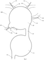
- a pistonless combustor 100 comprises a first combustion chamber 10, a second combustion chamber 11 and preferably a pre-combustion chamber 12.
- the pre-combustion chamber 12 forms a cavity or a protrusion on the periphery or wall of the first combustion chamber 10.
- the volume of the pre-combustion chamber 12 is at most 10 % of the volume of the first combustion chamber 10.
- the pre-combustion chamber has a semi-open configuration in which there is a line of sight to each point in an inner wall of the pre-combustion chamber 12 from an opening connecting the pre-combustion chamber to the first combustion chamber.
- the pre-combustion chamber preferably comprises an ignition device 64 for igniting a fuel-air mixture within the pre-combustion chamber.
- the ignition device can be for example a spark plug, or a microwave, plasma or laser ignition system.
- the pre-combustion chamber 12 can be a pre-chamber or a torch ignition device known from prior art internal combustion piston engines.
- the first combustion chamber can have a shaped wall section 13 for aligning one or more input valves, such as a first input valve 21, a second input valve 31 or a fifth input valve 41.
- the shaped wall section 13 is used for aligning the fifth input valve 41.
- a passage 14 connects the first combustion chamber 10 to the second combustion chamber. Fluids, such as air, exhaust gas and fuel can flow freely through the passage 14 between the first combustion chamber and the second combustion chamber. The flow of fluids through the passage is preferably not controlled by any valves.
- the exhaust gas and any other remaining fluids exit the pistonless combustor through output channel 15 which is preferably in connection with the second combustion chamber 11.
- the pistonless combustor 100 comprises only one combustion chamber, i.e.
- the passage 14 is positioned asymmetrically to the inlets and input valves, and the passage has a kidney-shaped cross-section. In general, an asymmetric positioning of the passage 14 compared to the input valves 21, 22, 31,32, 41, 42 has been found preferable.
- the output channel 15 is preferably located opposite to the passage 14 such that flow from the passage 14 is directed away from the output channel 15. Such direction of flow hinders the flow from the passage 14 to the output channel 15 thereby creating a third flow component 93 within the second combustion chamber and allows for any remaining fuel to be combusted in the second combustion chamber 11. Aligning the output channel 15 to a direction opposite to the direction of the third flow component 93 further hinders the flow leaving the second combustion chamber 11 through the output channel 11 but at the same time it reduces efficiency of scavenging.
- the second combustion chamber 11 does not have any fuel inputs and the purpose of the second combustion chamber is only to combust any remaining fuel in an air-rich environment.
- the second combustion chamber enables an increased burn rate, an improved pressure gain capability and it can be used to reduce NOx emissions.
- the first combustion chamber 10 preferably has a spherical inner wall having minor deviations such as input valves 21, 31, 41, 61, the pre-combustion chamber 12, the shaped wall section 13 and the passage 14.
- the first combustion chamber 10 has a toroidal inner wall having minor deviations such as input valves 21, 31, 41, 61, the pre-combustion chamber 12, the shaped wall section 13 and the passage 14.
- the first combustion chamber 10 has a cylindrical inner wall having minor deviations such as input valves 21, 31, 41, 61, the pre-combustion chamber 12, the shaped wall section 13 and the passage 14.
- the second combustion chamber 11 preferably has a spherical inner wall having minor deviations such as the passage 14 and the output channel 15.
- the second combustion chamber 11 has a toroidal inner wall having minor deviations such as the passage 14 and the output channel 15.
- the second combustion chamber 11 has a cylindrical inner wall having minor deviations such as the passage 14 and the output channel 15.
- a number of inlets 23, 33, 43 lead to the first combustion chamber and the inlets are controlled with valves 21, 31, 43.
- a first inlet 23 controlled by a first input valve 21 can be used for scavenging the first combustion chamber 10 and the second combustion chamber 11.
- An input flow of air can be provided through the first inlet 23 which flows through the first combustion chamber and the second combustion chamber thereby scavenging the pistonless combustor 100.
- the scavenging fills the combustion chambers with air while forcing exhaust gas to output channel 15.
- Positioning and aligning of the first inlet 23 and the first input valve 21 are designed to facilitate scavenging of the pistonless combustor.
- the first combustion chamber can comprise also a third inlet 24 controlled by a third input valve 22 for the same function.
- the positioning and alignment of the third inlet and the third input valve is similar to the first inlet and the first input valve, and in addition they are positioned and aligned symmetrically or asymmetrically compared to each other. Asymmetric positioning and alignment both increase possibilities to adjust the flows within the first combustion chamber.
- a second inlet 33 controlled by a second input valve 31 can be used for input of air, fuel or air-fuel mixture to the first combustion chamber 10.
- the second inlet 33 and the second input valve 31 are positioned and aligned to produce a first flow component 91 into the first combustion chamber 10.
- the second inlet 33 and the second input valve 31 are positioned and aligned to produce an eccentric flow, i.e. a flow directed a certain distance off from a center off the first combustion chamber.
- the second inlet 33 and the second input valve 31 are also positioned and aligned to produce an eccentric flow a certain distance off from the passage 14, or a certain distance off from the output channel 15 in case of a pistonless combustor having a single combustion chamber.
- the first combustion chamber can comprise also a fourth inlet 34 controlled by a fourth input valve 32 for the same function.
- the positioning and alignment of the fourth inlet and the fourth input valve can be similar to the second inlet and the second input valve but the size of the valve is different - or vice versa. This can create a second flow component 92 in the first combustion chamber. Preferably, in addition they are positioned and aligned symmetrically or asymmetrically compared to each other. Asymmetric positioning and alignment both increase possibilities to adjust the flows within the first combustion chamber.
- the second inlet and input valves, or both the second and fourth inlets and input valves can also provide the air for scavenging, and in that case the first and third inlets and input valves can be omitted.
- a fifth inlet 43 controlled by a fifth input valve 41 can be used for input of air, fuel or air-fuel mixture to the first combustion chamber 10.
- the input is provided in a form of a high-speed jet.
- the jet has an initial velocity of at least 0,1 Mach, preferably at least 0,2 Mach.
- the fifth inlet 43 and the fifth input valve 41 are positioned and aligned to either produce or strengthen a second flow component 92 into the first combustion chamber 10, or to increase turbulence in the first combustion chamber.
- the second flow component is not parallel to the first flow component 91.
- the fifth inlet 43 and the fifth input valve 41 are positioned and aligned to produce an eccentric flow, i.e. a flow directed a certain distance off from a center off the first combustion chamber.
- the fifth inlet 43 and the fifth input valve 41 are also positioned and aligned to produce an eccentric flow a certain distance off from the passage 14, or a certain distance off from the output channel 15 in case of a pistonless combustor having a single combustion chamber.
- the fifth inlet 43 and the fifth input valve 41 are positioned on the shaped wall section 13 of the first combustion chamber 10.
- the shaped wall section can be for example a planar wall section or a wall section having a different curvature than the majority of the first combustion chamber.
- the first combustion chamber can comprise also a sixth inlet 44 controlled by a sixth input valve 42 for the same function.
- the positioning and alignment of the sixth inlet and the sixth input valve is similar to the fifth inlet and the fifth input valve, and in addition they are positioned and aligned symmetrically or asymmetrically compared to each other. Asymmetric positioning and alignment both increase possibilities to adjust the flows within the first combustion chamber.
- both the fifth input valve 41 and the sixth input valve 43 are positioned on the shaped wall section 13 and a distance 51 of the fifth inlet 42 from a center line 50 of the first combustion chamber is different than a distance 52 of the sixth inlet 44 from the center line 50 of the first combustion chamber.
- the fifth and sixth inlet channel can be air channels and the fifth and sixth input valves can be air valves.
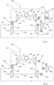
- Figures 2A to 2D disclose four different examples of systems where the pistonless combustor 100 is used to generate electric energy.
- an air input 101 is provided for a low-pressure compressor 121.
- the low-pressure compressor has a common shaft 122 with a low-pressure turbine 120 and a low-pressure generator 125.
- the output 123 from the low-pressure compressor flows to a first heat exchanger 140 which cools the compressed air.
- the cooled compressed air is an input 109 for a high-pressure compressor 111.
- the high-pressure compressor has a common shaft 112 with a high-pressure turbine 110 and a high-pressure generator 115.
- An output from the high-pressure compressor 111 is divided into an input 113 to the pistonless combustor 100 and into a high-pressure bypass flow 114. Any embodiment of the pistonless combustor 100 presented in the present disclosure can be used.
- the pistonless combustor uses the high-pressure air input and fuel input to produce an output 116 which is directed to the high-pressure turbine 110 which rotates the shaft 112 which in turn rotates the high-pressure generator 115 to generate electric energy.
- the output 119 from the high-pressure turbine is directed to the low-pressure turbine 120 which rotates the shaft 122 which in turn rotates the low-pressure generator 125 to generate electric energy.
- An output 139 from the low-pressure generator is directed to a second heat exchanger 141 which removes heat from the output flow 139 and the cooled output flow 143 is released from the system through exhaust.
- a flow from an external heat source can be arranged to the second heat exchanger, the first heat exchanger or both of them either in parallel or in series.
- the high-pressure bypass flow 114 from the high-pressure compressor 111 is divided into an input 117 to the first heat exchanger 140 and a flow 118 to the second heat exchanger 141.
- the division can either be controlled, e.g. with one or more valves, or uncontrolled, i.e. based on pressure differences.
- the input 117 to the first heat exchanger is heated in the first heat exchanger 140 using the heat extracted from the output 123 from the low-pressure compressor 121.
- the heated output 142 from the first heat exchanger 140 is combined to the flow 118 to the second heat exchanger 141, thereby creating an input 149 to the second heat exchanger 141.
- the second heat exchanger heats the input 149 using the heat extracted from the output 139 of the low-pressure turbine 120.
- the heated output 129 of the second heat exchanger 141 is directed to an auxiliary turbine 130 rotating an auxiliary generator 135 with a shaft 132.
- an input 102 from an external source can be combined to the high-pressure bypass flow 114.
- the input 102 can be direct to the first heat exchanger, the second heat exchanger, or both together with the high-pressure bypass flow 114.
- the external source is preferably an output of a wastegate of a turbocharger of an external combustion engine, but also other high temperature, high pressure sources can be utilized.
- an air input 201 is provided for a low-pressure compressor 221.
- the low-pressure compressor has a common shaft 222 with a low-pressure turbine 220 and a low-pressure generator 225.
- the output 223 from the low-pressure compressor flows to a first heat exchanger 240 which cools the compressed air.
- the cooled compressed air is an input 209 for a high-pressure compressor 211.
- the high-pressure compressor has a common shaft 212 with a high-pressure turbine 210 and a high-pressure generator 215.
- An output from the high-pressure compressor 211 is divided into an input 213 to the pistonless combustor 100 and into a high-pressure bypass flow 214. Any embodiment of the pistonless combustor 100 presented in the present disclosure can be used.
- the pistonless combustor uses the high-pressure air input and fuel input to produce an output 216 which is directed to the high-pressure turbine 210 which rotates the shaft 212 which in turn rotates the high-pressure generator 215 to generate electric energy.
- the output 219 from the high-pressure turbine is directed to the low-pressure turbine 220 which rotates the shaft 222 which in turn rotates the low-pressure generator 225 to generate electric energy.
- An output from the low-pressure generator is released from the system through exhaust.
- the high-pressure bypass flow 214 from the high-pressure compressor 211 is directed into an input 217 to the first heat exchanger 240.
- an input 202 from an external source can be combined to the high-pressure bypass flow 214.
- the external source is preferably an output of a wastegate of a turbocharger of an external combustion engine, but also other high temperature, high pressure sources can be utilized.
- the high-pressure bypass flow 214 optionally combined with the input 202 is the input 217 to the first heat exchanger which is heated in the first heat exchanger 240 using the heat extracted from the output 223 from the low-pressure compressor 221.
- the heated output 242 from the first heat exchanger 240 is directed to an auxiliary turbine 230 rotating an auxiliary generator 235 with a shaft 232.
- an air input 301 is provided for a low-pressure compressor 321.
- the low-pressure compressor has a common shaft 322 with a low-pressure turbine 320 and a low-pressure generator 325.
- the output from the low-pressure compressor is an input 309 for a high-pressure compressor 311.
- the high-pressure compressor has a common shaft 312 with a high-pressure turbine 310 and a high-pressure generator 315.
- An output from the high-pressure compressor 311 is divided into an input 313 to the pistonless combustor 100 and into a high-pressure bypass flow 314. Any embodiment of the pistonless combustor 100 presented in the present disclosure can be used.
- the pistonless combustor uses the high-pressure air input and fuel input to produce an output 316 which is directed to the high-pressure turbine 310 which rotates the shaft 312 which in turn rotates the high-pressure generator 315 to generate electric energy.
- the output 319 from the high-pressure turbine is directed to the low-pressure turbine 320 which rotates the shaft 322 which in turn rotates the low-pressure generator 325 to generate electric energy.
- An output 339 from the low-pressure generator is directed to a second heat exchanger 341 which removes heat from the output flow 339 and the cooled output flow 343 is released from the system through exhaust.
- a flow from an external heat source can be arranged to the second heat exchanger.
- the high-pressure bypass flow 314 from the high-pressure compressor 311 is directed to the second heat exchanger 341.
- an input 302 from an external source can be combined to the high-pressure bypass flow 314.
- the external source is preferably an output of a wastegate of a turbocharger of an external combustion engine, but also other high temperature, high pressure sources can be utilized.
- the high-pressure bypass flow 314 optionally combined with the input 302 is the input 349 to the second heat exchanger 341.
- the second heat exchanger heats the input 349 using the heat extracted from the output 339 of the low-pressure turbine 320.
- the heated output 329 of the second heat exchanger 341 is directed to an auxiliary turbine 330 rotating an auxiliary generator 335 with a shaft 332.
- a high-pressure input 402 from an external source, such as a turbocharger of an external combustion engine is an input to the pistonless combustor 100.
- Any embodiment of the pistonless combustor 100 presented in the present disclosure can be used.
- the pistonless combustor uses the high-pressure input 402 and fuel input to produce an output 416 which is directed to the high-pressure turbine 410 which rotates a shaft 412 which in turn rotates a high-pressure generator 415 to generate electric energy.
- the output 419 from the high-pressure turbine is directed to a low-pressure turbine 420 which rotates a shaft 422 which in turn rotates a low-pressure generator 425 to generate electric energy.
- An output 439 from the low-pressure generator is released from the system through exhaust.
- each of the first heat exchanger and the second heat exchanger can be a single heat exchanger or two or more heat exchanger connected in series or in parallel.
- the input from a wastegate 102, 202, 302, 402 of an external turbo charger could also be an input directly from an external turbocharger.
- An aspect of the invention is a pistonless combustor 100 (also referred as “the combustor") comprising at least one input channel 33, 34, 43, 44, 63 for air and fuel, an output channel 15, and a first combustion chamber 10.
- the combustor is a deflagration combustor where detonation combustion is avoided.
- Said at least one input channel 33, 34, 43, 44, 63 is controlled with a valve 31, 32, 41, 42, 61.
- the output channel 15 is constantly open to the first combustion chamber 10.
- one or more of the at least one input channel 33, 34, 43, 44, 63 has an eccentric alignment configured to produce an eccentric input flow of air creating a self-preserving flow pattern 91, 92 of a fuel-air mixture within the first combustion chamber 10.
- fuel is mixed with air within one or more of the at least one input channel to produce a fuel-air mixture.
- two or more of the at least one input channel 33, 34, 43, 44, 63 has an eccentric alignment configured to produce an eccentric input flow of air creating a self-preserving flow pattern of a fuel-air mixture within the first combustion chamber 10.
- the self-preserving flow pattern preferably comprises combined swirl flow and tumble flow.
- the swirl flow is initiated by one input channel and the tumble flow is initiated by another input channel.
- the eccentric input flow has a ratio e/r of at least 0,1 and at most 0,3, where e is a distance 51, 52 between a centre of the first combustion chamber and a line of alignment of the one or more of the at least one input channel, and where r is a distance 53 between the centre of the combustion chamber and an inner surface of an exterior wall of the first combustion chamber.
- the geometry of the first combustion 10 chamber facilitates maintaining of the combined swirl flow and tumble flow by means of the first combustion chamber having an internal shape that is at least substantially one of the following: toroidal, spherical and cylindrical.
- the pistonless combustor further comprises an air channel controlled by an air valve and having an eccentric alignment, the air channel being configured to supply air or fuel-air mixture into the combustion chamber for maintaining the combined swirl flow and tumble flow within the first combustion chamber.
- the combustor comprises a pre-combustion chamber 12 having smaller volume than the first combustion chamber.
- the pre-combustion chamber 12 forms a cavity or a protrusion on the periphery of the first combustion chamber 10.
- the volume of the pre-combustion chamber is at most 10 % of the volume of the first combustion chamber.
- the pre-combustion chamber has a semi-open configuration in which there is a line of sight to each point in an inner wall of the pre-combustion chamber from an opening connecting the pre-combustion chamber to the first combustion chamber.
- the passage 14 connects the first combustion chamber 10 to a second combustion chamber 11 and the output channel 15 is in connection with the second combustion chamber.
- the passage 14 is configured to be constantly open between the first combustion chamber and the second combustion chamber.
- the combustor is configured to produce a flow pattern which enables use of an open passage but of course a valve controlled passage can also be used.
- the second combustion chamber 11 has a volume larger than the first combustion chamber but smaller than three times the volume of the first combustion chamber 10.
- the second combustion chamber 11 has a volume smaller than the first combustion chamber but larger than 25% of the volume of the first combustion chamber 10.
- the second combustion chamber 11 has a volume larger than a quarter of the first combustion chamber but smaller than three times the volume of the first combustion chamber 10.
- the output channel 15 connects the first combustion chamber to a pressure wave charger.
- the output channel is configured to be constantly open between the first combustion chamber and the pressure wave charger, i.e. the pressure wave charger replaces the second combustion chamber 11 presented in some embodiments of the present disclosure.
- the pistonless combustor is configured to produce a flow pattern which enables use of an open output channel 15 but of course a valve-controlled output channel can also be used.
- the pistonless combustor comprises at least one input channel (23, 24) for air only, at least one input channel (33, 34, 43, 44) for air which may include fuel and at least one input channel (33, 34, 43, 44, 63) for fuel which may include air.
- the pistonless combustor (100) preferably comprises also at least one air input channel (43, 44) configured to input air jets having initial air velocity at least Mach 0,2.
- a combustion system comprises a single pistonless combustor 100 and a source of compressed air, such as a compressor 111, and a turbine 110 configured to received combustion products from the combustor and generate electric energy by rotating a generator 115.
- a source of compressed air such as a compressor 111
- a turbine 110 configured to received combustion products from the combustor and generate electric energy by rotating a generator 115.
- a combustion system comprises one or more pistonless combustors and a source of compressed air, such as a compressor, and a turbine configured to received combustion products from the combustor and generate electric energy by rotating a generator.
- a portion of air from compressor output is led to the combustor to cool down the combustor.
- Said portion of air is heated by the combustor and the system is configured to direct the flow of heated air to the turbine or to an auxiliary turbine configured to operate the compressor or the generator or an auxiliary generator.
- the combustion system is configured to direct the flow from the turbine to a heat exchanger.
- Said heat exchanger transfers heat from an external heat source and/or the heat released from the heated air flow coming from the turbine into a flow or air coming from the compressor.
- This flow heated by the heat exchanger is directed to the turbine or to the auxiliary turbine configured to operate the compressor or the generator or the auxiliary generator.
- Water or steam, or both water and steam can be introduced to said heated flow from the compressor in a controlled manner using one or more valves.
- Said one or more valves can be e.g. rotating valves or electrically controlled valves.
- the flow of heated air to the turbine or to the auxiliary turbine can be configured to flow through narrow passages.
- the pistonless combustor in general can also in a method where timing of air and fuel inputs to a combustor is used for initiating and maintaining a flow pattern having two flow components to achieve fast deflagration combustion in a pistonless combustor.
- the embodiments of the pistonless combustor 100 of the present disclosure can also be used in the method.
- An advantage of the method is that the flow pattern (91, 92, 93) is maintained within the combustor and pressure can rise even in case of an open output. A significant pressure gain can be achieved with the combustion process by optimising velocity of heat release with the method.
- FIG. 6 an example of a timing diagram is disclosed.
- the diagram shows a time slot for each input valve and each input valve is opened and closed in each cycle within the respective time slot.
- One working cycle of the pistonless combustor is divided to time units from 0 to 1000 and Figure 6 shows a single cycle starting from 0 units and ending to 1000 time units, the latter marking a reference point 600.
- a time slot 601 for the first input valve starts from 750 units before the reference point and ends at the reference point.
- the first input valve 21 can be used for e.g. input of air for scavenging the pistonless combustor.
- a time slot 602 for the second input valve starts from 450 time units before the reference point and ends at the reference point.
- the second input valve 31 can be used for e.g. input of fuel and air.
- Figure 6 does not show a time slot for the third input valve 22 but in an embodiment, the third input valve 22 is also used for scavenging the pistonless combustor with air like the first input valve 21 and a similar time slot could be used for the third input valve as is used for the first input valve.
- Figure 6 does not show a time slot for the fourth input valve 32 but in an embodiment, the fourth input valve 32 is also used for input of fuel and air like the second input valve 31 and a similar time slot could be used for the fourth input valve 32 as is used for the second input valve 31.
- a time slot 605 for the fifth input valve 41 starts from 170 time units before the reference point and ends 100 time units after the reference points.
- the fifth input valve 41 can be used for e.g. input of fuel and air.
- a time slot 610 for ignition is shown and it starts from 70 time units before the reference point and ends at 60 time units after the reference point 600. The ignition takes place within the time slot 610.
- FIG. 7 shows a time slot for each input valve and each input valve is opened and closed in each cycle within the respective time slot.
- One working cycle of the pistonless combustor is divided to time units from 0 to 1000 and Figure 7 shows a single cycle starting from 0 units and ending to 1000 time units, the latter marking a reference point 600.
- a time slot 601 for the first input valve starts from 750 units before the reference point and ends at the reference point.
- the first input valve 21 can be used for e.g. input of air for scavenging the pistonless combustor.
- a time slot 602 for the second input valve 31 starts from 450 time units before the reference point and ends at the reference point.
- the second input valve 31 can be used for e.g. input of fuel and air.
- Figure 7 does not show a time slot for the third input valve 22 but in an embodiment, the third input valve is also used for scavenging the pistonless combustor with air like the first input valve and a similar time slot could be used for the third input valve as is used for the first input valve.
- Figure 7 does not show a time slot for the fourth input valve 32 but in an embodiment, the fourth input valve 32 is also used for input of fuel and air like the second input valve 31 and a similar time slot could be used for the fourth input valve 32 as is used for the second input valve 31.
- a time slot 605 for the fifth input valve 41 starts from 170 time units before the reference point and ends 100 time units after the reference points.
- the fifth input valve 41 can be used for e.g. input of fuel and air.
- a time slot 607 for the seventh input valve 61 starts from 160 time units before the reference point and end 65 time units after the reference.
- the seventh input valve 61 can be used for e.g. input of fuel and air to e.g. an ignition area such as the pre-combustion chamber 12.
- a time slot 610 for ignition is shown and it starts from 70 time units before the reference point and ends at 60 time units after the reference point 600. The ignition takes place within the time slot 610.
- An aspect of the invention is a method of controlling a deflagration combustion process in a pistonless combustor.
- the combustion process consists of repeating working cycles divided to equally long time units, e.g. from 0 to 1000.
- the division to time units is artificial and any number of time units can be used to divide a single cycle.
- the method comprises a step of opening a first input valve 21 and introducing air into the first combustion chamber 10 of the pistonless combustor 100.
- a purpose of this air input is to scavenge combustion products of a previous cycle from the pistonless combustor.
- the first input valve is preferably opened at earliest 750 time units before a reference point 600 and preferably closed at latest at the reference point 600.
- the first input valve can be a single valve 21 or a set of valves 21, 23, such as a combination of two or more valves.
- the size, shape and other physical properties may or may not vary between the set of valves. Timing between the valves of the set of valves can be adjusted individually.
- the first input valve 21 can be opened at earliest 600, 680 or 800 time units before the reference point 600.
- the reference point 600 is a closing event of a second input valve 31.
- the reference point could be any other defined point in a cycle.
- the reference point is merely an anchor to which timings of all events are tied to.
- the method further comprises a step of opening a second input valve 31 after opening the first input valve 21 and introducing air into the combustor.
- the input of air via the second input valve thereby preferably initiates a flow pattern having a first flow component 91 within the first combustion chamber 10.
- the second input valve is preferably opened at earliest 450 time units before a reference point and closed at the reference point.
- the closing event of the second input valve defines the reference point.
- the second input valve can be a single valve 31 or a set of valves 31, 33, such as a combination of two or more valves.
- the size, shape and other physical properties may or may not vary between the set of valves. Timing between the valves of the set of valves can be adjusted individually.
- the second input valve 31 can be opened at earliest 300, 350 or 400 time units before the reference point.
- the method also comprises a step opening a fifth input valve 41 after opening the second input valve 31 and introducing air into the combustor.
- the air input of the fifth input valve is in a nonparallel angle in relation to the input through the second input valve thereby creating a second flow component to the flow pattern within the combustor for increasing speed of combustion propagation.
- the fifth input valve is preferably opened at earliest 170 time units before a reference point and the fifth input valve is preferably closed at latest 100 time units after the reference point.
- the fifth input valve 41 can be a single valve or a set of valves, such as a combination of two or more valves, such as the fifth input valve 41 and the sixth input valve 42.
- the size, shape and other physical properties may or may not vary between the set of valves. Timing between the valves of the set of valves can be adjusted individually.
- the fifth input valve can be opened at earliest 150, 160 or 200 time units before the reference point.
- the method further comprises a step of introducing fuel from any input valve opening after the opening of the first input valve 21, wherein the fuel is mixed into the air creating a fuel-air mixture flowing within the flow pattern.
- a step of introducing fuel from any input valve opening after the opening of the first input valve 21, wherein the fuel is mixed into the air creating a fuel-air mixture flowing within the flow pattern Preferably an input of fuel-air mixture through either the second input valve 31, the fourth input valve 33, the fifth input valve 41, the sixth input valve 43, the seventh input valve 61, or any combination of them or even all of them, is used instead of pure air input.
- the method still comprises a step of igniting the fuel-air mixture within the pistonless combustor thereby increasing pressure within the pistonless combustor.
- the ignition is performed preferably at earliest 40 units before the reference point and preferably at latest 60 units after the reference point,
- the method further comprises a step of opening a seventh input valve 61 and introducing fuel-air mixture into an ignition area.
- Ignition area is a space within the combustor in which said ignition step takes place and an additional fuel-air mixture input facilitates ignition of the whole content of the combustor.
- the ignition are is a pre-combustion chamber 12 as disclosed in the present disclosure.
- the seventh input valve 61 is preferably opened at earliest 160 time units before the reference point and closed preferably at latest 65 units after the reference point.
- the seventh input valve can be a single valve or a set of valves, such as a combination of two or more valves. The size, shape and other physical properties may or may not vary between the set of valves. Timing between the valves of the set of valves can be adjusted individually.
- the seventh input valve can be opened at earliest 150, 160 or 200 time units before the reference point.
- the second input valve 31, the fifth input valve 41 or both of them have an eccentric alignment producing an eccentric input flow of air for initiating and maintaining the flow pattern of the fuel-air mixture within the combustor.
- the eccentric alignment means that the input is directed off-center, i.e. directed to miss the center point of the combustor.
- the eccentric alignment together with shaping of the combustor can create the flow pattern 91, 92 within the combustor.
- the first flow component 91 is a swirl flow and the second flow component 92 is a tumble flow.
- the first flow component is a tumble flow and the second flow component is a swirl flow.
- the first flow component and the second flow component are two vortices non-parallel between each other.
- geometry of the combustor facilitates maintaining of the combined swirl flow and tumble flow. This is achieved by means of the combustor having an internal shape that is at least substantially one of the following: toroidal, spherical and cylindrical.
- the pistonless combustor has an output channel 15 that is constantly open.
- the flow pattern within the combustor enables use of the constantly open output channel 15.
- an output channel controlled with an output valve can also be used but it is not essential and it leads to a more complicated solution.
- a second aspect of the present disclosure is a method of controlling deflagration combustion process in a pistonless combustor.
- the second aspect relates to controlling of a deflagration combustion process in a pistonless combustor.
- An object of the second aspect is thus to provide a method which eliminates or alleviates the above disadvantages.
- the object of the invention is achieved by a method which is characterized by what is stated in embodiment A below.
- the preferred embodiments of the second aspect are disclosed in embodiments B-K below.
- the second aspect is based on the idea of timing air and fuel inputs to a combustor to initiate and maintain a flow pattern having two flow components to achieve fast deflagration combustion in a pistonless combustor.
- An advantage of the method of the second aspect of the invention is that the flow pattern is maintained within the combustor and pressure can rise even in case of an open output. A significant pressure gain can be achieved with the combustion process by optimising velocity of heat release with the method of the second aspect.
- Example 1 based on prototype.
- Example 1 Combustor volume 1 liter Operating frequency 17 Hz Liquid fuel, gasoline Open Close Input 1 438 811 Input 2 734 1000 Input 5 842 942 Input 7 892 942 Spark 974 974 Table 2.
- Example 2 based on simulation.
- Example 2 Combustor volume 22 litres Operating frequency 15 Hz Liquid fuel, kerosene Open Close Input 1 300 736 Input 2 697 1000 Input 5 902 1000 Input 7 905 961 Spark 961 961 Table 3.
- Example 3 based on simulation.
- Example 3 Combustor volume 500 litres Operating frequency 5 Hz Gaseous fuel, methane Open Close Input 1 388 744 Input 2 677 1000 Input 5 859 957 Input 7 905 961 Spark 975 975
Landscapes
- Engineering & Computer Science (AREA)
- Chemical & Material Sciences (AREA)
- Combustion & Propulsion (AREA)
- Mechanical Engineering (AREA)
- General Engineering & Computer Science (AREA)
- Fluidized-Bed Combustion And Resonant Combustion (AREA)
- Combustion Methods Of Internal-Combustion Engines (AREA)
Applications Claiming Priority (4)
| Application Number | Priority Date | Filing Date | Title |
|---|---|---|---|
| FI20195488A FI129141B (en) | 2019-06-09 | 2019-06-09 | A method for controlling a deflagration combustion process in a piston-free combustion chamber |
| FI20195487A FI129140B (en) | 2019-06-09 | 2019-06-09 | Combustion chamber without piston |
| PCT/FI2020/050398 WO2020249862A1 (en) | 2019-06-09 | 2020-06-08 | Method of controlling deflagration combustion process in pistonless combustor |
| EP20758262.8A EP3980693B1 (de) | 2019-06-09 | 2020-06-08 | Verfahren zur steuerung des deflagrationsverbrennungsprozesses in einer kolbenlosen brennkammer |
Related Parent Applications (1)
| Application Number | Title | Priority Date | Filing Date |
|---|---|---|---|
| EP20758262.8A Division EP3980693B1 (de) | 2019-06-09 | 2020-06-08 | Verfahren zur steuerung des deflagrationsverbrennungsprozesses in einer kolbenlosen brennkammer |
Publications (2)
| Publication Number | Publication Date |
|---|---|
| EP4286673A2 true EP4286673A2 (de) | 2023-12-06 |
| EP4286673A3 EP4286673A3 (de) | 2024-02-21 |
Family
ID=72148163
Family Applications (2)
| Application Number | Title | Priority Date | Filing Date |
|---|---|---|---|
| EP23203129.4A Pending EP4286673A3 (de) | 2019-06-09 | 2020-06-08 | Verfahren zur steuerung des deflagrationsverbrennungsprozesses in einer kolbenlosen brennkammer |
| EP20758262.8A Active EP3980693B1 (de) | 2019-06-09 | 2020-06-08 | Verfahren zur steuerung des deflagrationsverbrennungsprozesses in einer kolbenlosen brennkammer |
Family Applications After (1)
| Application Number | Title | Priority Date | Filing Date |
|---|---|---|---|
| EP20758262.8A Active EP3980693B1 (de) | 2019-06-09 | 2020-06-08 | Verfahren zur steuerung des deflagrationsverbrennungsprozesses in einer kolbenlosen brennkammer |
Country Status (4)
| Country | Link |
|---|---|
| US (2) | US12241407B2 (de) |
| EP (2) | EP4286673A3 (de) |
| CN (2) | CN118129189A (de) |
| WO (1) | WO2020249862A1 (de) |
Families Citing this family (2)
| Publication number | Priority date | Publication date | Assignee | Title |
|---|---|---|---|---|
| EP4113008A1 (de) * | 2021-07-01 | 2023-01-04 | Siemens Energy Global GmbH & Co. KG | Wasserstoffbefeuertes brennkammersystem, verfahren und anlage |
| FI130655B1 (en) * | 2022-12-20 | 2024-01-08 | Finno Exergy Oy | Method for controlling a deflagration combustion process in a combustion chamber without a piston |
Family Cites Families (37)
| Publication number | Priority date | Publication date | Assignee | Title |
|---|---|---|---|---|
| US1346509A (en) * | 1918-09-14 | 1920-07-13 | Ernst J Ohnell | Explosion gas-turbine |
| US1982665A (en) * | 1928-04-30 | 1934-12-04 | Holzwarth Gas Turbine Co | Explosion turbine |
| US2010823A (en) * | 1930-12-11 | 1935-08-13 | Holzwarth Gas Turbine Company | Method of and apparatus for supercharging explosion chambers |
| US2054081A (en) * | 1931-06-12 | 1936-09-15 | Holzwarth Gas Turbine Co | Explosion gas turbine and method of operating same |
| DE638234C (de) * | 1932-04-28 | 1936-11-12 | E H Hans Holzwarth Dr Ing | Verfahren zum Betriebe von Verpuffungskammern, insbesondere fuer Brennkraftturbinen |
| US2049446A (en) * | 1932-08-23 | 1936-08-04 | Holzwarth Gas Turbine Co | Explosion turbine with full admission high speed rotor |
| US2399394A (en) * | 1940-12-07 | 1946-04-30 | Bbc Brown Boveri & Cie | Pressure exchanger |
| CH233945A (de) * | 1942-12-29 | 1944-08-31 | Sulzer Ag | Verfahren zur Erzeugung von Treibgasen mittels schwingender Gase und Gaskolben-Treibgaserzeuger zur Ausübung des Verfahrens. |
| US2614387A (en) * | 1946-09-17 | 1952-10-21 | Ingersoll Rand Co | Intermittent explosion unit for gas turbine plants |
| US2480626A (en) * | 1947-11-03 | 1949-08-30 | Jr Albert G Bodine | Resonant wave pulse engine and process |
| US3043368A (en) * | 1958-04-21 | 1962-07-10 | Midland Ross Corp | Method of high speed heating |
| GB1274728A (en) * | 1969-09-26 | 1972-05-17 | Rolls Royce | Combustion equipment |
| GB1275119A (en) * | 1969-10-27 | 1972-05-24 | Rolls Royce | Combustion equipment |
| DE2232025A1 (de) * | 1972-06-30 | 1974-01-17 | Motoren Turbinen Union | Gasturbinenanlage, insbesondere triebwerk mit gleichraumverbrennung |
| US4138842A (en) * | 1975-11-05 | 1979-02-13 | Zwick Eugene B | Low emission combustion apparatus |
| US4218426A (en) * | 1976-04-09 | 1980-08-19 | Continental Carbon Company | Method and apparatus for the combustion of waste gases |
| DE2844095C2 (de) * | 1978-10-10 | 1984-10-31 | Ludwig Dipl.-Ing. Dr.-Ing. 7000 Stuttgart Huber | Schwingfeuergerät |
| JPS6093211A (ja) * | 1983-10-28 | 1985-05-25 | Toshiba Corp | パルス燃焼装置 |
| US4651712A (en) * | 1985-10-11 | 1987-03-24 | Arkansas Patents, Inc. | Pulsing combustion |
| US4856981A (en) * | 1988-05-24 | 1989-08-15 | Gas Research Institute | Mixing rate controlled pulse combustion burner |
| JPH01310204A (ja) * | 1988-06-06 | 1989-12-14 | Paloma Ind Ltd | パルス燃焼器の燃焼室 |
| US4928481A (en) * | 1988-07-13 | 1990-05-29 | Prutech Ii | Staged low NOx premix gas turbine combustor |
| US5025622A (en) * | 1988-08-26 | 1991-06-25 | Sol-3- Resources, Inc. | Annular vortex combustor |
| US5158445A (en) * | 1989-05-22 | 1992-10-27 | Institute Of Gas Technology | Ultra-low pollutant emission combustion method and apparatus |
| JP3517957B2 (ja) * | 1994-06-10 | 2004-04-12 | マツダ株式会社 | エンジンの吸気ポート構造およびその設定方法 |
| US7621118B2 (en) * | 2002-07-03 | 2009-11-24 | Rolls-Royce North American Technologies, Inc. | Constant volume combustor having a rotating wave rotor |
| KR100830316B1 (ko) * | 2002-08-09 | 2008-05-19 | 제이에프이 스틸 가부시키가이샤 | 관상화염버너, 그 연소제어방법 및 장치 |
| US6920761B2 (en) * | 2003-01-03 | 2005-07-26 | Dennis A. Laper | High efficiency low hydrocarbon emmisson hybrid power plant using operational aspects of both internal combustion and jet engines |
| US6931862B2 (en) * | 2003-04-30 | 2005-08-23 | Hamilton Sundstrand Corporation | Combustor system for an expendable gas turbine engine |
| JP2005120995A (ja) * | 2003-10-20 | 2005-05-12 | Nissan Motor Co Ltd | 吸気ポート用の仕切り板、吸気ポート成形用砂中子およびシリンダヘッド |
| ITTO20031041A1 (it) * | 2003-12-24 | 2005-06-25 | Fiat Ricerche | Combustore rotativo, e generatore elettrico comprendente un tale combustore. |
| US9140456B2 (en) * | 2011-12-01 | 2015-09-22 | General Electric Company | Variable initiation location system for pulse detonation combustor |
| BR112015010472A2 (pt) * | 2012-11-07 | 2017-07-11 | Exponential Tech Inc | aparelho e método de combustão de ganho de pressão |
| WO2015159956A1 (ja) * | 2014-04-18 | 2015-10-22 | 大石 光江 | 燃焼ガスを駆動力として噴出するエンジン |
| US20160102609A1 (en) * | 2014-10-09 | 2016-04-14 | United Technologies Corporation | Pulse detonation combustor |
| FI127178B (en) * | 2016-02-09 | 2017-12-29 | Finno Energy Oy | A combustion chamber arrangement and a system comprising said arrangement |
| WO2019122514A1 (en) * | 2017-12-22 | 2019-06-27 | Finno Energy Oy | System and method for generating power |
-
2020
- 2020-06-08 EP EP23203129.4A patent/EP4286673A3/de active Pending
- 2020-06-08 CN CN202410387950.8A patent/CN118129189A/zh active Pending
- 2020-06-08 CN CN202080054147.2A patent/CN114207356B/zh active Active
- 2020-06-08 WO PCT/FI2020/050398 patent/WO2020249862A1/en not_active Ceased
- 2020-06-08 EP EP20758262.8A patent/EP3980693B1/de active Active
- 2020-06-08 US US17/617,373 patent/US12241407B2/en active Active
-
2025
- 2025-01-27 US US19/037,773 patent/US20250179959A1/en active Pending
Also Published As
| Publication number | Publication date |
|---|---|
| EP3980693A1 (de) | 2022-04-13 |
| EP3980693B1 (de) | 2023-11-22 |
| CN118129189A (zh) | 2024-06-04 |
| US20250179959A1 (en) | 2025-06-05 |
| WO2020249862A1 (en) | 2020-12-17 |
| CN114207356B (zh) | 2024-04-19 |
| CN114207356A (zh) | 2022-03-18 |
| US20220252005A1 (en) | 2022-08-11 |
| US12241407B2 (en) | 2025-03-04 |
| EP4286673A3 (de) | 2024-02-21 |
Similar Documents
| Publication | Publication Date | Title |
|---|---|---|
| US20250179959A1 (en) | Method of controlling deflagration combustion process in pistonless combustor | |
| CN104153884B (zh) | 一种旋转爆震燃气轮机 | |
| US3877219A (en) | Constant volume combustion gas turbine with intermittent flows | |
| US20070033945A1 (en) | Gas turbine system and method of operation | |
| AU2009287383B2 (en) | Combustion turbine in which combustion is intermittent | |
| CN204082338U (zh) | 一种旋转爆震燃气轮机 | |
| US20260104006A1 (en) | Rotating internal combustion engine | |
| CN205190043U (zh) | 燃气涡轮发动机 | |
| Akbari et al. | Numerical simulation and design of a combustion wave rotor for deflagrative and detonative propagation | |
| US10240794B2 (en) | Thermal and thrust management in dynamic pressure exchangers | |
| FI129141B (en) | A method for controlling a deflagration combustion process in a piston-free combustion chamber | |
| FI129140B (en) | Combustion chamber without piston | |
| US20260117975A1 (en) | Method of controlling deflagration combustion process in pistonless combustor | |
| CN106337738B (zh) | 连续旋转爆震坦克 | |
| CN206205998U (zh) | 连续旋转爆震坦克 | |
| CN107084049B (zh) | 一种基于旋转爆轰燃烧的船用三轴燃气轮机 | |
| US11286866B2 (en) | Intermittent injection system for a gas turbine combustor | |
| CN116291873A (zh) | 一种带补燃爆震燃烧室的燃气轮机 | |
| CN106895439A (zh) | 一种高效低污染核心机 | |
| CN107100735B (zh) | 一种基于组合式燃烧室的船用燃气轮机 | |
| KR101984397B1 (ko) | 로터, 터빈 및 이를 포함하는 가스터빈 | |
| JP2025009603A (ja) | 背圧を下げ、推力を下げず、最高温度を下げるターボファンサイクル | |
| CN107313859A (zh) | 一种基于组合式燃烧室的发电燃气轮机 |
Legal Events
| Date | Code | Title | Description |
|---|---|---|---|
| PUAI | Public reference made under article 153(3) epc to a published international application that has entered the european phase |
Free format text: ORIGINAL CODE: 0009012 |
|
| STAA | Information on the status of an ep patent application or granted ep patent |
Free format text: STATUS: REQUEST FOR EXAMINATION WAS MADE |
|
| 17P | Request for examination filed |
Effective date: 20231012 |
|
| AC | Divisional application: reference to earlier application |
Ref document number: 3980693 Country of ref document: EP Kind code of ref document: P |
|
| AK | Designated contracting states |
Kind code of ref document: A2 Designated state(s): AL AT BE BG CH CY CZ DE DK EE ES FI FR GB GR HR HU IE IS IT LI LT LU LV MC MK MT NL NO PL PT RO RS SE SI SK SM TR |
|
| REG | Reference to a national code |
Ref country code: DE Ref legal event code: R079 Free format text: PREVIOUS MAIN CLASS: F02C0005120000 Ipc: F23R0007000000 |
|
| PUAL | Search report despatched |
Free format text: ORIGINAL CODE: 0009013 |
|
| STAA | Information on the status of an ep patent application or granted ep patent |
Free format text: STATUS: EXAMINATION IS IN PROGRESS |
|
| AK | Designated contracting states |
Kind code of ref document: A3 Designated state(s): AL AT BE BG CH CY CZ DE DK EE ES FI FR GB GR HR HU IE IS IT LI LT LU LV MC MK MT NL NO PL PT RO RS SE SI SK SM TR |
|
| RIC1 | Information provided on ipc code assigned before grant |
Ipc: F23R 3/58 20060101ALI20240118BHEP Ipc: F02C 5/12 20060101ALI20240118BHEP Ipc: F23N 5/20 20060101ALI20240118BHEP Ipc: F23R 7/00 20060101AFI20240118BHEP |
|
| 17Q | First examination report despatched |
Effective date: 20240219 |
|
| RBV | Designated contracting states (corrected) |
Designated state(s): AL AT BE BG CH CY CZ DE DK EE ES FI FR GB GR HR HU IE IS IT LI LT LU LV MC MK MT NL NO PL PT RO RS SE SI SK SM TR |
|
| GRAP | Despatch of communication of intention to grant a patent |
Free format text: ORIGINAL CODE: EPIDOSNIGR1 |
|
| STAA | Information on the status of an ep patent application or granted ep patent |
Free format text: STATUS: GRANT OF PATENT IS INTENDED |