EP4286598A1 - Fuel feeding guide and work machine - Google Patents
Fuel feeding guide and work machine Download PDFInfo
- Publication number
- EP4286598A1 EP4286598A1 EP21923246.9A EP21923246A EP4286598A1 EP 4286598 A1 EP4286598 A1 EP 4286598A1 EP 21923246 A EP21923246 A EP 21923246A EP 4286598 A1 EP4286598 A1 EP 4286598A1
- Authority
- EP
- European Patent Office
- Prior art keywords
- fuel supply
- support member
- body member
- fuel
- groove
- Prior art date
- Legal status (The legal status is an assumption and is not a legal conclusion. Google has not performed a legal analysis and makes no representation as to the accuracy of the status listed.)
- Granted
Links
Images







Classifications
-
- E—FIXED CONSTRUCTIONS
- E02—HYDRAULIC ENGINEERING; FOUNDATIONS; SOIL SHIFTING
- E02F—DREDGING; SOIL-SHIFTING
- E02F9/00—Component parts of dredgers or soil-shifting machines, not restricted to one of the kinds covered by groups E02F3/00 - E02F7/00
- E02F9/08—Superstructures; Supports for superstructures
- E02F9/0858—Arrangement of component parts installed on superstructures not otherwise provided for, e.g. electric components, fenders, air-conditioning units
- E02F9/0883—Tanks, e.g. oil tank, urea tank, fuel tank
-
- E—FIXED CONSTRUCTIONS
- E02—HYDRAULIC ENGINEERING; FOUNDATIONS; SOIL SHIFTING
- E02F—DREDGING; SOIL-SHIFTING
- E02F3/00—Dredgers; Soil-shifting machines
- E02F3/04—Dredgers; Soil-shifting machines mechanically-driven
- E02F3/28—Dredgers; Soil-shifting machines mechanically-driven with digging tools mounted on a dipper- or bucket-arm, i.e. there is either one arm or a pair of arms, e.g. dippers, buckets
- E02F3/30—Dredgers; Soil-shifting machines mechanically-driven with digging tools mounted on a dipper- or bucket-arm, i.e. there is either one arm or a pair of arms, e.g. dippers, buckets with a dipper-arm pivoted on a cantilever beam, i.e. boom
- E02F3/32—Dredgers; Soil-shifting machines mechanically-driven with digging tools mounted on a dipper- or bucket-arm, i.e. there is either one arm or a pair of arms, e.g. dippers, buckets with a dipper-arm pivoted on a cantilever beam, i.e. boom working downwardly and towards the machine, e.g. with backhoes
- E02F3/325—Backhoes of the miniature type
-
- B—PERFORMING OPERATIONS; TRANSPORTING
- B60—VEHICLES IN GENERAL
- B60K—ARRANGEMENT OR MOUNTING OF PROPULSION UNITS OR OF TRANSMISSIONS IN VEHICLES; ARRANGEMENT OR MOUNTING OF PLURAL DIVERSE PRIME-MOVERS IN VEHICLES; AUXILIARY DRIVES FOR VEHICLES; INSTRUMENTATION OR DASHBOARDS FOR VEHICLES; ARRANGEMENTS IN CONNECTION WITH COOLING, AIR INTAKE, GAS EXHAUST OR FUEL SUPPLY OF PROPULSION UNITS IN VEHICLES
- B60K15/00—Arrangement in connection with fuel supply of combustion engines or other fuel consuming energy converters, e.g. fuel cells; Mounting or construction of fuel tanks
- B60K15/03—Fuel tanks
- B60K15/04—Tank inlets
-
- B—PERFORMING OPERATIONS; TRANSPORTING
- B60—VEHICLES IN GENERAL
- B60K—ARRANGEMENT OR MOUNTING OF PROPULSION UNITS OR OF TRANSMISSIONS IN VEHICLES; ARRANGEMENT OR MOUNTING OF PLURAL DIVERSE PRIME-MOVERS IN VEHICLES; AUXILIARY DRIVES FOR VEHICLES; INSTRUMENTATION OR DASHBOARDS FOR VEHICLES; ARRANGEMENTS IN CONNECTION WITH COOLING, AIR INTAKE, GAS EXHAUST OR FUEL SUPPLY OF PROPULSION UNITS IN VEHICLES
- B60K15/00—Arrangement in connection with fuel supply of combustion engines or other fuel consuming energy converters, e.g. fuel cells; Mounting or construction of fuel tanks
- B60K15/03—Fuel tanks
- B60K15/063—Arrangement of tanks
-
- F—MECHANICAL ENGINEERING; LIGHTING; HEATING; WEAPONS; BLASTING
- F02—COMBUSTION ENGINES; HOT-GAS OR COMBUSTION-PRODUCT ENGINE PLANTS
- F02M—SUPPLYING COMBUSTION ENGINES IN GENERAL WITH COMBUSTIBLE MIXTURES OR CONSTITUENTS THEREOF
- F02M37/00—Apparatus or systems for feeding liquid fuel from storage containers to carburettors or fuel-injection apparatus; Arrangements for purifying liquid fuel specially adapted for, or arranged on, internal-combustion engines
-
- B—PERFORMING OPERATIONS; TRANSPORTING
- B60—VEHICLES IN GENERAL
- B60K—ARRANGEMENT OR MOUNTING OF PROPULSION UNITS OR OF TRANSMISSIONS IN VEHICLES; ARRANGEMENT OR MOUNTING OF PLURAL DIVERSE PRIME-MOVERS IN VEHICLES; AUXILIARY DRIVES FOR VEHICLES; INSTRUMENTATION OR DASHBOARDS FOR VEHICLES; ARRANGEMENTS IN CONNECTION WITH COOLING, AIR INTAKE, GAS EXHAUST OR FUEL SUPPLY OF PROPULSION UNITS IN VEHICLES
- B60K15/00—Arrangement in connection with fuel supply of combustion engines or other fuel consuming energy converters, e.g. fuel cells; Mounting or construction of fuel tanks
- B60K15/03—Fuel tanks
-
- B—PERFORMING OPERATIONS; TRANSPORTING
- B60—VEHICLES IN GENERAL
- B60K—ARRANGEMENT OR MOUNTING OF PROPULSION UNITS OR OF TRANSMISSIONS IN VEHICLES; ARRANGEMENT OR MOUNTING OF PLURAL DIVERSE PRIME-MOVERS IN VEHICLES; AUXILIARY DRIVES FOR VEHICLES; INSTRUMENTATION OR DASHBOARDS FOR VEHICLES; ARRANGEMENTS IN CONNECTION WITH COOLING, AIR INTAKE, GAS EXHAUST OR FUEL SUPPLY OF PROPULSION UNITS IN VEHICLES
- B60K15/00—Arrangement in connection with fuel supply of combustion engines or other fuel consuming energy converters, e.g. fuel cells; Mounting or construction of fuel tanks
- B60K15/03—Fuel tanks
- B60K2015/03118—Multiple tanks, i.e. two or more separate tanks
-
- B—PERFORMING OPERATIONS; TRANSPORTING
- B60—VEHICLES IN GENERAL
- B60K—ARRANGEMENT OR MOUNTING OF PROPULSION UNITS OR OF TRANSMISSIONS IN VEHICLES; ARRANGEMENT OR MOUNTING OF PLURAL DIVERSE PRIME-MOVERS IN VEHICLES; AUXILIARY DRIVES FOR VEHICLES; INSTRUMENTATION OR DASHBOARDS FOR VEHICLES; ARRANGEMENTS IN CONNECTION WITH COOLING, AIR INTAKE, GAS EXHAUST OR FUEL SUPPLY OF PROPULSION UNITS IN VEHICLES
- B60K15/00—Arrangement in connection with fuel supply of combustion engines or other fuel consuming energy converters, e.g. fuel cells; Mounting or construction of fuel tanks
- B60K15/03—Fuel tanks
- B60K2015/03118—Multiple tanks, i.e. two or more separate tanks
- B60K2015/03151—Mechanical connection between the tanks
-
- B—PERFORMING OPERATIONS; TRANSPORTING
- B60—VEHICLES IN GENERAL
- B60K—ARRANGEMENT OR MOUNTING OF PROPULSION UNITS OR OF TRANSMISSIONS IN VEHICLES; ARRANGEMENT OR MOUNTING OF PLURAL DIVERSE PRIME-MOVERS IN VEHICLES; AUXILIARY DRIVES FOR VEHICLES; INSTRUMENTATION OR DASHBOARDS FOR VEHICLES; ARRANGEMENTS IN CONNECTION WITH COOLING, AIR INTAKE, GAS EXHAUST OR FUEL SUPPLY OF PROPULSION UNITS IN VEHICLES
- B60K15/00—Arrangement in connection with fuel supply of combustion engines or other fuel consuming energy converters, e.g. fuel cells; Mounting or construction of fuel tanks
- B60K15/03—Fuel tanks
- B60K2015/03184—Exchangeable tanks, i.e. the empty tank is replaced by refilled tank
-
- B—PERFORMING OPERATIONS; TRANSPORTING
- B60—VEHICLES IN GENERAL
- B60K—ARRANGEMENT OR MOUNTING OF PROPULSION UNITS OR OF TRANSMISSIONS IN VEHICLES; ARRANGEMENT OR MOUNTING OF PLURAL DIVERSE PRIME-MOVERS IN VEHICLES; AUXILIARY DRIVES FOR VEHICLES; INSTRUMENTATION OR DASHBOARDS FOR VEHICLES; ARRANGEMENTS IN CONNECTION WITH COOLING, AIR INTAKE, GAS EXHAUST OR FUEL SUPPLY OF PROPULSION UNITS IN VEHICLES
- B60K15/00—Arrangement in connection with fuel supply of combustion engines or other fuel consuming energy converters, e.g. fuel cells; Mounting or construction of fuel tanks
- B60K15/03—Fuel tanks
- B60K2015/03328—Arrangements or special measures related to fuel tanks or fuel handling
-
- B—PERFORMING OPERATIONS; TRANSPORTING
- B60—VEHICLES IN GENERAL
- B60K—ARRANGEMENT OR MOUNTING OF PROPULSION UNITS OR OF TRANSMISSIONS IN VEHICLES; ARRANGEMENT OR MOUNTING OF PLURAL DIVERSE PRIME-MOVERS IN VEHICLES; AUXILIARY DRIVES FOR VEHICLES; INSTRUMENTATION OR DASHBOARDS FOR VEHICLES; ARRANGEMENTS IN CONNECTION WITH COOLING, AIR INTAKE, GAS EXHAUST OR FUEL SUPPLY OF PROPULSION UNITS IN VEHICLES
- B60K15/00—Arrangement in connection with fuel supply of combustion engines or other fuel consuming energy converters, e.g. fuel cells; Mounting or construction of fuel tanks
- B60K15/03—Fuel tanks
- B60K15/04—Tank inlets
- B60K2015/0458—Details of the tank inlet
- B60K2015/0496—Details of the tank inlet the fuel inlet being arranged on the top of the fuel tank
-
- B—PERFORMING OPERATIONS; TRANSPORTING
- B60—VEHICLES IN GENERAL
- B60K—ARRANGEMENT OR MOUNTING OF PROPULSION UNITS OR OF TRANSMISSIONS IN VEHICLES; ARRANGEMENT OR MOUNTING OF PLURAL DIVERSE PRIME-MOVERS IN VEHICLES; AUXILIARY DRIVES FOR VEHICLES; INSTRUMENTATION OR DASHBOARDS FOR VEHICLES; ARRANGEMENTS IN CONNECTION WITH COOLING, AIR INTAKE, GAS EXHAUST OR FUEL SUPPLY OF PROPULSION UNITS IN VEHICLES
- B60K15/00—Arrangement in connection with fuel supply of combustion engines or other fuel consuming energy converters, e.g. fuel cells; Mounting or construction of fuel tanks
- B60K15/03—Fuel tanks
- B60K15/063—Arrangement of tanks
- B60K2015/0638—Arrangement of tanks the fuel tank is arranged in the rear of the vehicle
-
- B—PERFORMING OPERATIONS; TRANSPORTING
- B60—VEHICLES IN GENERAL
- B60Y—INDEXING SCHEME RELATING TO ASPECTS CROSS-CUTTING VEHICLE TECHNOLOGY
- B60Y2200/00—Type of vehicle
- B60Y2200/40—Special vehicles
- B60Y2200/41—Construction vehicles, e.g. graders, excavators
-
- B—PERFORMING OPERATIONS; TRANSPORTING
- B60—VEHICLES IN GENERAL
- B60Y—INDEXING SCHEME RELATING TO ASPECTS CROSS-CUTTING VEHICLE TECHNOLOGY
- B60Y2200/00—Type of vehicle
- B60Y2200/40—Special vehicles
- B60Y2200/41—Construction vehicles, e.g. graders, excavators
- B60Y2200/412—Excavators
Definitions
- the present invention relates to a fuel supply guide and a working machine including the fuel supply guide.
- the working machine disclosed in PTL 1 includes a fuel tank mounted on a machine body.
- the fuel tank has a tank body for storing a fuel, and a fuel supply port provided on the upper side of the tank body.
- an object of the present invention is to ease work of transferring a fuel from a fuel supply tank to a fuel tank.
- a fuel supply guide to be used to supply a fuel by using a fuel supply tank to a fuel tank that includes a tank body for storing the fuel and a fuel supply port on an upper side of the tank body.
- the fuel supply guide includes a support member provided on an upper portion of the fuel tank; and a body member projecting from the support member in a direction away from the fuel supply port as the body member extends upward and projecting higher than the fuel supply port.
- the body member is capable of receiving the fuel supply tank by an upper portion thereof to support the fuel supply tank.
- the body member is attachable to and detachable from the support member.
- the support member includes a first support member closer to a first vertical surface of the fuel tank extending in an up-down direction, and a second support member closer to a second vertical surface of the fuel tank opposite to the first vertical surface.
- the body member includes a first member inserted into the first support member in an insertable/extractable manner, a second member inserted into the second support member in an insertable/extractable manner, and a coupling member to couple the first member and the second member to each other.
- the body member is supported by the support member to be shiftable between a usage position for placing the fuel supply tank thereon and a storage position in which the body member faces a surface of the fuel tank extending in an up-down direction.
- the support member has a guide groove along a vertical surface of the fuel tank extending in the up-down direction.
- the guide groove guides the body member to be shiftable between the usage position and the storage position.
- the body member includes a main member formed of a long material, a first engagement portion provided at an intermediate portion in a longitudinal direction of the main member, and a second engagement portion provided closer to an end in the longitudinal direction of the main member.
- the body member is disposed with the longitudinal direction of the main member coinciding with the up-down direction such that the second engagement portion is positioned below the first engagement portion in a state of being in the storage position.
- the guide groove has a first groove to guide the first engagement portion and the second engagement portion to be movable in the up-down direction, and a second groove branched from an intermediate portion of the first groove to guide the second engagement portion.
- the main member is shifted from the storage position to the usage position by moving the first engagement portion and the second engagement portion upward along the first groove, and then moving the second engagement portion along the second groove by rotating the main member around the first engagement portion.
- the guide groove has a third groove to hold the main member in the usage position as a result of the second engagement portion being fitted to the third groove when the main member is in the usage position.
- the body member is supported by the support member to be shiftable between a usage position for placing the fuel supply tank thereon and a storage position in which the body member is in a position at an upper portion of the fuel tank and extends in a horizontal direction.
- the fuel supply guide includes a lock member to lock the body member.
- the support member is disposed at an upper portion of the fuel tank in the horizontal direction.
- the body member includes a pivotally supported portion pivotably supported by one end portion of the support member in the horizontal direction. The body member is shiftable between the usage position and the storage position by being rotated around the pivotally supported portion.
- the lock member is bridged over the body member and the support member and locks the body member in the usage position when the body member is in the usage position.
- the support member has a first locking groove formed to be spaced from the pivotally supported portion toward another end of the support member in the horizontal direction, a second locking groove formed to be spaced from the first locking groove toward the other end, and a third locking groove formed to be spaced from the second locking groove toward the other end.
- the body member includes a first locking portion provided at an end portion thereof opposite to an end portion thereof provided with the pivotally supported portion.
- the lock member includes a pivotally attached portion provided closer to one end thereof and pivotally attached to an intermediate portion of the body member, and a second locking portion provided closer to another end thereof and to be fitted to the first locking groove to lock the body member in the usage position when the body member is in the usage position.
- a working machine includes the fuel supply guide.
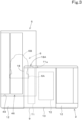
- FIG. 1 is a schematic plan view illustrating an overall configuration of a working machine 1 according to the present embodiment.
- FIG. 2 is a schematic side view of the working machine 1.
- FIG. 3 is a rear view of the working machine 1.
- a backhoe which is a swiveling work machine, is presented as an example of the working machine 1.
- the working machine 1 includes a machine body (swivel base) 2, a traveling device 3, and a working device 4.
- a cabin 5 is mounted on the machine body 2.
- An operator's seat (seat) 6 on which a driver (operator) is to sit is provided in the interior of the cabin 5.
- the operator's seat 6 is mounted on the machine body 2, and the cabin 5 surrounds the operator's seat 6.
- the operator's seat 6 includes a seat portion 6A that is a portion for a driver to sit thereon, and a back portion 6B that is a portion for receiving the back of the driver.
- the direction (the arrow A1 direction in FIG. 1 and FIG. 2 ) toward the front of a driver (operator) sitting on the operator's seat 6 of the working machine 1 will be described as forward
- the direction (the arrow A2 direction in FIG. 1 and FIG. 2 ) toward the rear of the driver will be described as rearward
- the arrow K1 direction in FIG. 1 and FIG. 2 will be described as the front-rear direction
- leftward (the arrow B1 direction in FIG. 1 ) of the driver will be described as leftward
- rightward (the arrow B2 direction in FIG. 1 ) of the driver will be described as rightward.
- machine-body width direction K2 (the width direction of the machine body 2).
- a direction from a central portion of the machine body 2 in the width direction toward a right portion or a left portion thereof will be described as machine-body-outward (outward in the machine-body width direction K2).
- machine-body-outward is a direction that is in the machine-body width direction K2 and that is away from the center of the machine body 2 in the width direction.
- a direction opposite to the machine-body-outward will be described as machine-body-inward (inward in the machine-body width direction K2).
- machine-body-inward is a direction that is in the machine-body width direction K2 and that is toward the center of the machine body 2 in the width direction.
- the traveling device 3 is a crawler traveling device that supports the machine body 2 so as to be capable of traveling.
- the traveling device 3 includes a travel frame 3A, a first traveling device 3L provided leftward of the travel frame 3A, and a second traveling device 3R provided rightward of the travel frame 3A.
- the first traveling device 3L is driven by a first traveling motor M1
- the second traveling device 3R is driven by a second traveling motor M2.
- a dozer device 7 is mounted on a front portion of the traveling device 3.
- the machine body 2 is supported on the travel frame 3A via a swivel bearing 8 so as to be capable of swiveling around a swiveling axis X1.
- the machine body 2 is driven to swivel by a swivel motor M3.
- the machine body 2 includes a base (hereinafter referred to as the swiveling base) 9 supported by the swivel bearing 8 to be capable of swiveling around the swiveling axis X1.
- the swiveling base 9 is formed of a steel sheet or the like and constitutes a bottom portion of the machine body 2.
- a vertical rib 9A which is a reinforcing member, is provided from a front portion to a rear portion of the upper surface of the swiveling base 9.
- a support member or the like that supports a mounted object, such as a device mounted on the machine body 2 is provided on the swiveling base 9.
- a swiveling frame that serves as the framework of the machine body 2 is thereby formed. The periphery of the swiveling frame in the horizontal direction is covered by a swiveling cover 12.
- a fuel tank T1 for storing a fuel of a prime mover E1 and a hydraulic fluid tank T2 for storing a hydraulic fluid are disposed adjacent to each other in the machine-body width direction K2 on a rear portion of the machine body 2.
- the fuel tank T1 is disposed rearward of the cabin 5 and the operator's seat 6.
- the fuel tank T1 is attached to an attachment member fixed at a lower portion thereof to the swiveling base 9, and projects upward from the swiveling base 9 (a lower portion of the machine body 2).
- a weight 10 is disposed rearward of the fuel tank T1 and the hydraulic fluid tank T2 to face the fuel tank T1 and the hydraulic fluid tank T2 in the front-rear direction K1.
- the upper end of the fuel tank T1 is at a height position that is substantially identical to the height position of the upper end of the weight 10.
- the fuel tank T1 has a shape (vertically elongated shape) whose height is relatively high and sectional area in the horizontal direction is relatively small. Specifically, the fuel tank T1 has a shape whose height in the up-down direction is larger than the width thereof in the machine-body width direction K2 and the width thereof in the front-rear direction.
- a space 46 is provided rearward of the cabin 5.
- the space 46 is formed, rearward of the cabin 5, machine-body-outward.
- the space 46 is defined by the right side surface of a cover member 18 covering the fuel tank T1, the right side surface of the weight 10, the back surface of the cabin 5, and a step (floor surface) 49 forming the lower surface of the space 46.
- the space 46 is open upward, rearward, and leftward.
- the upper wall of the cover member 18 includes an openable lid 18A that openably closes a housing space for the fuel tank T1.
- the openable lid 18A is pivotably supported at a front end portion thereof by a hinge or the like and is capable of opening a portion above the fuel tank T1 (a portion above the housing space for the fuel tank T1) by being upwardly swung around the front end portion as indicated by the two-dot-chain line in FIG. 2 .
- the step 49 is provided at a position near a lower end portion of the cabin 5 and forms the upper surface of the machine body 2 to allow an operator to step thereon.
- the fuel tank T1 is disposed in the vicinity of the step 49. Therefore, when supplying a fuel to the fuel tank T1, it is possible for an operator to perform work of supplying the fuel to the fuel tank T1 in a state in which the openable lid 18A of the cover member 18 is opened and in which the operator is on the step 49.
- the cabin 5 is mounted on one side portion (left side portion) of the machine body 2 in the width direction K2.
- the prime mover E1 is mounted on the other side portion (right side portion) of the machine body 2 in the width direction K2.
- the prime mover E1 is a diesel engine.
- the prime mover E1 may be a gasoline engine and may be of a hybrid type including an engine and an electric motor.
- a rear portion of the prime mover E1 is provided with a hydraulic pump P1.
- the hydraulic pump P1 is driven by the prime mover E1 to pressurize and deliver a hydraulic fluid that is to be used for a hydraulic driver.
- a radiator R1 that cools cooling water of the prime mover E1, an oil cooler O1 that cools a hydraulic fluid, and a condenser D1 that cools refrigerant of an air conditioning apparatus (air-conditioner) mounted on the working machine 1 are disposed forward of the prime mover E1.
- a swivel joint S1 is provided at the position of the swiveling axis X1.
- the swivel joint S 1 is a rotating joint (rotary joint) that causes a hydraulic fluid to flow between a hydraulic machine on the machine body 2 and a hydraulic machine on the traveling device 3.
- a control valve V1 is disposed rearward of the swivel joint S1.
- the control valve V1 is a hydraulic machine in which control valves that control hydraulic actuators of a hydraulic cylinder, a hydraulic motor, and the like mounted on the working machine 1 are integrated.
- a swing bracket 21 is attached to a front portion of a support bracket 20 via a swing shaft 26 so as to be swingable around a vertical axis.
- the working device 4 is attached to the swing bracket 21.
- the working device 4 includes a boom 22, an arm 23, and a bucket (working tool) 24.
- a base portion 22A of the boom 22 is pivotally attached to an upper portion of the swing bracket 21 via a boom pivot 27 so as to be rotatable around a lateral axis (an axis extending in the machine-body width direction K2).
- the arm 23 is pivotally attached to the distal end of the boom 22 so as to be rotatable around the lateral axis.
- the bucket 24 is provided at the distal end of the arm 23 to be capable of shoveling and dumping.
- Shoveling is an operation of swinging the bucket 24 in a direction toward the boom 22 and is, for example, an operation of scooping earth and sand, or the like.
- Dumping is an operation of swinging the bucket 24 in a direction away from the boom 22 and is, for example, an operation of dropping (discharging) scooped earth and sand, or the like.
- a different working tool (hydraulic attachment) drivable by a hydraulic actuator can be mounted on the working machine 1.
- the different working tool are a hydraulic breaker, a hydraulic crusher, an angle broom, an earth auger, a pallet fork, a sweeper, a mower, a snow blower, and the like.
- the swing bracket 21 can be swung by the extension and contraction of a swing cylinder C2 included in the machine body 2.
- the boom 22 can be swung by the extension and contraction of a boom cylinder C3.
- the arm 23 can be swung by the extension and contraction of an arm cylinder C4.
- the bucket 24 can be caused to shovel and dump by the extension and contraction of a bucket cylinder (working tool cylinder) C5.
- the swing cylinder C2, the boom cylinder C3, the arm cylinder C4, and the bucket cylinder C5 are each constituted by a hydraulic cylinder.
- a manipulator 41 is provided in the interior of the cabin 5.
- the manipulator 41 is provided forward of the operator's seat 6.
- An operation unit 42 for operating (manipulating the machine body 2, the traveling device 3, the working device 4, the swing bracket 21, and the like) the working machine 1 includes the operator's seat 6 and the manipulator 41.
- the fuel tank T1 includes a tank body T1A for storing a fuel, and a fuel supply port T1a for inputting the fuel into the tank body T1A.
- the tank body T1A has a quadrangular column-like outer shape and has an upper surface 51, a bottom surface 52, and four vertical surfaces 53 (a first vertical surface 53a, a second vertical surface 53b, a third vertical surface 53c, and a fourth vertical surface 53d) extending in the up-down direction.
- the first vertical surface 53a is the left surface of the tank body T1A
- the second vertical surface 53b is the right surface of the tank body T1A
- the third vertical surface 53c is the front surface of the tank body T1A
- the fourth vertical surface 53d is the rear surface of the tank body T1A.
- the fuel supply port T1a is provided on the upper surface 51 of the tank body T1A.
- the fuel supply port T1a is provided at a central portion of the upper surface 51 of the tank body T1A in the machine-body width direction K2 to be rearward from a central portion of the upper surface 51 in the front-rear direction.
- a fuel supply guide 55 that is to be used to supply a fuel to the fuel tank T1 by using a fuel supply tank 54 (for example, a jerry can) is mounted in the present embodiment.
- the fuel supply guide 55 is used to reduce the operator's load of work of transferring a fuel from the fuel supply tank 54 to the fuel tank T1 when the fuel is to be supplied to the fuel tank T1 by using the fuel supply tank 54.
- the fuel supply guide 55 is provided on an upper portion of the fuel tank T1 and is used when a fuel is supplied to the fuel tank T1 from above by lifting the fuel supply tank 54 above the fuel tank T1.
- FIG. 4 , FIG. 5 , and FIG. 6 illustrate a first embodiment of the fuel supply guide 55.
- the fuel supply guide 55 includes a support member 56 provided on an upper portion of the fuel tank T1, and a body member 57 projecting in an inclined direction in which the body member 57 is shifted in a direction away from the fuel supply port T1a as the body member 57 extends upward from the support member 56.
- the body member 57 projects higher than the fuel supply port T1a and is capable of receiving the fuel supply tank 54 by an upper portion thereof and supporting the fuel supply tank 54. It is thus possible, when inserting a distal end portion of a fuel supply nozzle 54A connected to the fuel supply tank 54 into the fuel supply port T1a with one hand, to place the fuel supply tank 54 on the upper portion of the body member 57 and support the fuel supply tank 54 with the other hand while the weight of the fuel supply tank 54 is received by the fuel supply guide 55.
- the side of the fuel supply port T1a of the fuel supply tank 54 is tilted downward while the weight of the fuel supply tank 54 is received by the fuel supply guide 55, to thereby supply a fuel from the fuel supply tank 54 to the fuel tank T1. Consequently, it is possible to reduce the operator's load of work of transferring the fuel from the fuel supply tank 54 to the fuel tank T1. That is, it is also possible to reduce an operator's load during insertion of the distal end portion of the fuel supply nozzle 54A into the fuel supply port T1a and during supplying of the fuel.
- the support member 56 includes a first support member 56L closer to the first vertical surface 53a, and a second support member 56R closer to the second vertical surface 53b opposite to the first vertical surface 53a.
- the first support member 56L and the second support member 56R are each formed of a cylinder member having a bottomed cylindrical shape closed at one end thereof in the axial direction and opening at the other end thereof.
- the first support member 56L is disposed leftward of an upper portion of the first vertical surface 53a
- the second support member 56R is disposed rightward of an upper portion of the second vertical surface 53b.
- the support member 56 (the first support member 56L and the second support member 56R) is inclined to shift upward as the support member 56 extends rearward such that the opening side thereof is the upper side.
- the support member 56 (the first support member 56L and the second support member 56R) is disposed such that an upper portion thereof is at a position that is forward of the fourth vertical surface 53d (rear surface) of the fuel tank T1 and that corresponds to the fuel supply port T1a in a side view.
- the first support member 56L and the second support member 56R are attached to and supported by the fuel tank T1 or a member around the fuel tank T1.
- FIG. 5 illustrates an example in which the first support member 56L and the second support member 56R are attached to a bracket member 58 fixed to the fuel tank T1.
- the first support member 56L and the second support member 56R are, however, not limited thereto and may be attached to a member on the machine body 2, for example, to a bracket member extending from the cover member 18, the weight 10, the swiveling frame, or the like.
- the body member 57 includes a first member 57L, a second member 57R, and a coupling member 59.
- the first member 57L, the second member 57R, and the coupling member 59 are each formed of a bar member (round bar member).
- the first member 57L, the second member 57R, and the coupling member 59 are not each limited to a bar member.
- the first member 57L and the second member 57R are disposed parallel to each other with a space therebetween. A distance between the axes of the first member 57L and the second member 57R coincides with a distance between the axes of the first support member 56L and the second support member 56R.
- the coupling member 59 includes a first coupling rod 59A that couples one end portions of the first support member 56L and the second support member 56R to each other, and a second coupling rod 59B that couples intermediate portions of the first support member 56L and the second support member 56R to each other.
- first member 57L on the other end side in the axial direction is inserted into the first support member 56L.
- a portion of the second member 57R on the other end side in the axial direction is inserted into the second support member 56R.
- the portion of each of the first member 57L and the second member 57R on the other end side in the axial direction constitutes an insertion portion 57a inserted into the support member 56 in an insertable/extractable manner.
- the body member 57 can be attached to and detached from the support member 56 by inserting and extracting the insertion portion 57a into/from the support member 56.
- the body member 57 of the fuel supply guide 55 is mounted on the support member 56 when a fuel is to be supplied to the fuel tank T1 by using the fuel supply tank 54. When a fuel is not to be supplied to the fuel tank T1, the body member 57 can be dismounted from the support member 56 and stored in a storage space in the vicinity of the fuel tank T1.
- Each of the first member 57L and the second member 57R is not limited to a round bar and may be formed of a square bar or a plate material.
- the first support member 56L and the second support member 56R are formed in cylindrical shapes corresponding to the sectional shapes of the first member 57L and the second member 57R, respectively.
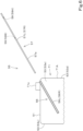
- FIG. 7A , FIG. 7B , FIG. 8 , and FIG. 9 illustrate a second embodiment of the fuel supply guide 55.
- the fuel supply guide 55 also includes the support member 56 disposed near an upper portion of the fuel tank T1, and a body member 57 projecting in an inclined direction in which the body member 57 is shifted in a direction (rearward) away from the fuel supply port T1a as the body member 57 extends upward from the support member 56.
- the body member 57 is supported by the support member 56 to be shiftable between a usage position Y1 (refer to FIG. 7A and FIG. 7B ) for placing the fuel supply tank 54 thereon and a storage position Y2 (refer to FIG. 9 ) in which the body member 57 extends along the side surfaces (vertical surfaces 53) of the fuel tank T1 extending in the up-down direction.
- the body member 57 is in the usage position Y1 when the fuel supply guide 55 is used, and the body member 57 is in the storage position Y2 when the fuel supply guide 55 is not used.
- the support member 56 is disposed along the vertical surfaces 53 of the fuel tank T1 to extend in the up-down direction.
- the support member 56 includes a first support member 60L disposed near and leftward of a rear portion of the first vertical surface 53a to extend along the first vertical surface 53a, and a second support member 60R disposed near and rightward of a rear portion of the first vertical surface 53a to extend along the second vertical surface 53b.
- the first support member 60L and the second support member 60R are each formed of a plate material.
- the first support member 60L includes a first portion 60a extending in the up-down direction, a second portion 60b extending in the up-down direction and positioned rearward of the first portion 60a with a space therebetween, a third portion 60c connecting lower end portions of the first portion 60a and the second portion 60b to each other, and a fourth portion 60d projecting forward from an upper portion of the first portion 60a.
- the second support member 60R is formed similarly to the first support member 60L. That is, the second support member 60R also includes the first portion 60a, the second portion 60b, the third portion 60c, and the fourth portion 60d that are the same as those of the first support member 60L.
- the first support member 60L and the second support member 60R are coupled to each other by a plurality of coupling members 61 (a first coupling plate 61A, a second coupling plate 61B, a third coupling plate 61C, and fourth coupling plate 61D).
- the first coupling plate 61A to the fourth coupling plate 61D are each formed of a band plate material extending in the machine-body width direction K2.
- the first coupling plate 61A couples upper portions of the first portion 60a of the first support member 60L and the first portion 60a of the second support member 60R to each other.
- the second coupling plate 61B couples upper portions of the second portion 60b of the first support member 60L and the second portion 60b of the second support member 60R to each other.
- the third coupling plate 61C couples, below the fourth portion 60d, intermediate portions of the first portion 60a of the first support member 60L and the first portion 60a of the second support member 60R to each other.
- the fourth coupling plate 61D couples lower end portions of the first support member 60L and the second support member 60R to each other.
- the support member 56 (the first support member 60L and the second support member 60R) has a guide groove 62 that guides the body member 57 so as to be shiftable between the usage position Y1 and the storage position Y2.
- the guide groove 62 has a first groove 62a, a second groove 62b, and a third groove 62c.
- the first groove 62a is a linear groove including the first portion 60a, the second portion 60b, and the third portion 60c and extending in the up-down direction.
- the first groove 62a is open to both sides in the machine-body width direction K2. Upper portions of the first portion 60a and the second portion 60b are not connected to each other. In other words, the first groove 62a is open upward. A bottom portion of the first groove 62a is closed by the third portion 60c.
- the second groove 62b is formed at the fourth portion 60d.
- the second groove 62b is an arc-shaped groove branched from an intermediate portion of the first groove 62a in the up-down direction. Specifically, the second groove 62b is an arc-shaped groove curved downward in a protruding shape. One end of the second groove 62b is continuous (in communication) with the first groove 62a.
- the second groove 62b has an inclined shape in which the second groove 62b is shifted upward as the second groove 62b extends forward from one end to the other end thereof.
- the third groove 62c is formed continuously from the other end of the second groove 62b. Specifically, the third groove 62c is formed to extend downward from the other end (upper end) of the second groove 62b, and the connection portion between the second groove 62b and the third groove 62c protrudes upward.
- the body member 57 includes a main member 64 formed of a long plate material (long material), a first engagement portion 65 provided at an intermediate portion in the longitudinal direction of the main member 64, and a second engagement portion 66 provided closer to an end in the longitudinal direction of the main member 64.
- the main member 64 includes a first member 64L supported by the first support member 60L, and a second member 64R supported by the second support member 60R.
- the first member 64L is disposed on the fuel tank T1 side (the right surface side) of the first support member 60L.
- the second member 64R is disposed on the fuel tank T1 side (the left surface side) of the second support member 60R.
- the first member 64L and the second member 64R are disposed parallel to each other with a space therebetween.
- One end portions of the first member 64L and the second member 64R in the longitudinal direction are coupled to each other by a first coupling rod 67A (coupling member 67) that serves as a placement portion for placing the fuel supply tank 54 thereon.
- Intermediate portions of the first member 64L and the second member 64R in the longitudinal direction are coupled to each other by a second coupling rod 67B (coupling member 67).
- the first engagement portion 65 includes a first projecting portion 65L, which is a portion of the second coupling rod 67B projecting from the first member 64L, and a second projecting portion 65R, which is a portion of the second coupling rod 67B projecting from the second member 64R.
- the second engagement portion 66 includes a first pin 66L fixed to the other end side of the first member 64L in the longitudinal direction, and a second pin 66R fixed the other end side of the second member 64R in the longitudinal direction.
- the body member 57 (main member 64) in the storage position Y2 is disposed to extend (such that the longitudinal direction thereof coincides with the up-down direction) along the first groove 62a in the up-down direction.
- an end portion 67a of the first coupling rod 67A, the first engagement portion 65, and the second engagement portion 66 are fitted to the first groove 62a and movable in the up-down direction in the first groove 62a.
- the end portion of the first coupling rod 67A is positioned at an upper portion of the first groove 62a
- the first engagement portion 65 is positioned at an intermediate portion of the first groove 62a and below the second groove 62b
- the second engagement portion 66 is positioned at the lower end of the first groove 62a.
- the main member 64 (body member 57) is shifted from the storage position Y2 to the usage position Y1 by moving the first engagement portion 65 and the second engagement portion 66 upward along the first groove 62a and then moving the second engagement portion 66 along the second groove 62b by rotating the main member 64 around the first engagement portion 65.
- the fuel tank T1 and the weight 10 are disposed with a sufficient space therebetween in the front-rear direction K1 to an extent that the support member 56 can be disposed rearward of the fuel tank T1.
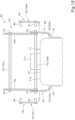
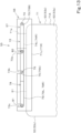
- FIG. 10 to FIG. 14 illustrate a third embodiment of the fuel supply guide 55.
- the fuel supply guide 55 also includes the support member 56 provided on an upper portion of the fuel tank T1, and a body member 57 projecting from the support member 56 in an inclined direction in which the body member 57 is shifted in a direction (rearward) away from the fuel supply port T1a as the body member 57 extends upward.
- the body member 57 is supported by the support member 56 to be shiftable between the usage position Y1 (refer to FIG. 10 ) for placing the fuel supply tank 54 thereon and the storage position Y2 (refer to FIG. 13 ) in which the body member 57 is in a position at an upper portion of the fuel tank T1 and extends in the horizontal direction.
- the support member 56 is formed of a plate material and is disposed at an upper portion of the fuel tank T1 to extend in the front-rear direction K1 (horizontal direction).
- the body member 57 includes a pivotally supported portion 70 pivotably supported by a rear portion (one end portion in the horizontal direction) of the support member 56 in the front-rear direction K1.
- the body member 57 is shiftable between the usage position Y1 and the storage position Y2 by rotating the body member 57 around the pivotally supported portion 70.
- the support member 56 includes a first support member 71L disposed leftward of an upper portion of the first vertical surface 53a of the fuel tank T1 to extend in the front-rear direction K1, and a second support member 71R disposed rightward of an upper portion of the second vertical surface 53b of the fuel tank T1 to extend in the front-rear direction K1.
- the support member 56 (the first support member 71L and the second support member 71R) has a first locking groove 73a, a second locking groove 73b, and a third locking groove 73c.
- the first locking groove 73a, the second locking groove 73b, and the third locking groove 73c are formed to extend downward from the upper end of the support member 56 to an intermediate portion of the support member 56 in the up-down direction. That is, the first locking groove 73a, the second locking groove 73b, and the third locking groove 73c are grooves that open upward and open to both sides in the machine-body width direction K2.
- the first locking groove 73a is formed to be spaced forward (toward the other end of the support member 56 in the horizontal direction) from the pivotally supported portion 70.
- the second locking groove 73b is formed to be spaced forward from the first locking groove 73a.
- the third locking groove 73c is formed to be spaced forward from the second locking groove 73b.
- the body member 57 includes a first member 74L pivotably supported by the first support member 71L, a second member 74R pivotably supported by the second support member 71R, and a coupling member 75 that couples the first member 74L and the second member 74R to each other.
- the first member 74L and the second member 74R are each formed of a long plate material (long material).
- the first member 74L and the second member 74R are disposed parallel to each other with a space therebetween.
- the coupling member 75 includes a first coupling rod 75A that couples one end portions of the first member 74L and the second member 74R in the longitudinal direction to each other, and a second coupling rod 75B that couples the other end portions of the first member 74L and the second member 74R in the longitudinal direction to each other.
- Each end portion of the second coupling rod 75B serves as the pivotally supported portion 70 that pivotably supports the body member 57 at the support member 56.
- one end portion of the second coupling rod 75B serves as the pivotally supported portion 70 that pivotably supports the first member 74L at the first support member 71L
- the other end portion of the second coupling rod 75B serves as the pivotally supported portion 70 that pivotably supports the second member 74R at the second support member 71R
- the first coupling rod 75A is a placement portion for placing the fuel supply tank 54 thereon.
- One end portion and the other end portion of the first coupling rod 75A each serve as a first locking portion 76 that can be fitted to the second locking groove 73b.
- the first locking portion 76 is provided at an end portion of the body member 57 opposite to an end portion thereof provided with the pivotally supported portion 70.
- the fuel supply guide 55 includes a lock member 78 that locks the body member 57 in the usage position Y1.
- the lock member 78 is bridged over the body member 57 and the support member 56 and locks the body member 57 in the usage position Y1.
- the lock member 78 includes a body plate 79 formed of a long plate material, a pivotally attached portion 80 provided at one end portion of the body plate 79 in the longitudinal direction, and a second locking portion 81 provided at the other end portion of the body plate 79 in the longitudinal direction.
- the pivotally attached portion 80 and the second locking portion 81 are each formed of a pin.
- the pivotally attached portion 80 is pivotally attached to an intermediate portion of the body member 57 in the longitudinal direction. The lock member 78 is thus rotatable around the pivotally attached portion 80 with respect to the body member 57.
- the body plate 79 of the lock member 78 includes a first plate member 79L pivotally attached to the first member 74L, and a second plate member 79R pivotally attached to the second member 74R.
- the first plate member 79L and the second plate member 79R are each provided with the pivotally attached portion 80 and the second locking portion 81.
- the body member 57 when the body member 57 is in the storage position Y2, the body member 57 is disposed in a state of extending, between the first support member 71L and the second support member 71R, along the support member 56 in the front-rear direction K1.
- the first locking portion 76 is fitted to the second locking groove 73b.
- the first locking portion 76 of the first member 74L is fitted to the second locking groove 73b of the first support member 71L
- the first locking portion 76 of the second member 74R is fitted to the second locking groove 73b of the second support member 71R. Consequently, the body member 57 is held in the storage position Y2.
- the lock member 78 is disposed at the same height position as the height position of the body member 57 to extend in the front-rear direction K1.
- the pivotally attached portion 80 is fitted to the first locking groove 73a, and the second locking portion 81 is fitted to the third locking groove 73c.
- the pivotally attached portion 80 of the first plate member 79L is fitted to the first locking groove 73a of the first support member 71L, and the second locking portion 81 of the first plate member 79L is fitted to the third locking groove 73c of the first support member 71L.
- the pivotally attached portion 80 of the second plate member 79R is fitted to the first locking groove 73a of the second support member 71R, and the second locking portion 81 of the second plate member 79R is fitted to the third locking groove 73c of the second support member 71R.
- the body member 57 To shift the body member 57 from the storage position Y2 to the usage position Y1, first, from the state in which the body member 57 is in the storage position Y2, the body member 57 is rotated upward as indicated by the solid lines in FIG. 14 around the pivotally supported portion 70, the pivotally attached portion 80 is disengaged from the first locking groove 73a, and the second locking portion 81 is disengaged from the third locking groove 73c.
- the body member 57 is rotated to a position (usage position Y1) in which the second locking portion 81 is fitted to the first locking groove 73a, and the second locking portion 81 is fitted to the first locking groove 73a in the state in which the body member 57 is in the usage position Y1.
- usage position Y1 a position in which the second locking portion 81 is fitted to the first locking groove 73a
- the second locking portion 81 is fitted to the first locking groove 73a in the state in which the body member 57 is in the usage position Y1.
- the second locking portion 81 being fitted to the first locking groove 73a, the rotation of the body member 57 around the pivotally supported portion 70 is restricted, and the body member 57 is locked in the usage position Y1.
- the first vertical surface 53a of the fuel tank T1 is the left surface
- the second vertical surface 53b thereof is the right surface.
- the first vertical surface 53a and the second vertical surface 53b of the fuel tank T1 may be the front surface and the rear surface, respectively
- the first vertical surface 53a and the second vertical surface 53b thereof may be the rear surface and the front surface, respectively
- the first vertical surface 53a and the second vertical surface 53b thereof may be the right surface and the left surface, respectively.
- the direction in which the fuel supply guide 55 projects is rearward in the present embodiment
- the direction in which the fuel supply guide 55 projects may be forward, leftward, or rightward depending on a place where the fuel tank T1 is installed.
- the aforementioned fuel supply guide 55 is to be used to supply a fuel by using the fuel supply tank 54 to the fuel tank T1 that includes the tank body T1A for storing the fuel and the fuel supply port T1a on the upper side of the tank body T1A.
- the fuel supply guide 55 includes the support member 56 provided on an upper portion of the fuel tank T1, and the body member 57 that projects from the support member 56 in a direction away from the fuel supply port T1a as the body member 57 extends upward and that projects higher than the fuel supply port T1a.
- the body member 57 is capable of receiving the fuel supply tank 54 by an upper portion thereof to support the fuel supply tank 54.
- the body member 57 is attachable to and detachable from the support member 56.
- the body member 57 can be dismounted and stored when not in use.
- the support member 56 includes the first support member 56L closer to the first vertical surface 53a of the fuel tank T1 extending in the up-down direction, and the second support member 56R closer to the second vertical surface 53b of the fuel tank T1 opposite to the first vertical surface 53a.
- the body member 57 includes the first member 57L inserted into the first support member 56L in an insertable/extractable manner, the second member 57R inserted into the second support member 56R in an insertable/extractable manner, and the coupling member 59 coupling the first member 57L and the second member 57R to each other.
- the body member 57 is supported by the support member 56 to be shiftable between the usage position Y1 for placing the fuel supply tank 54 thereon and the storage position Y2 in which the body member 57 faces a surface of the fuel tank T1 extending in the up-down direction.
- the body member 57 can be compactly stored when not in use.
- the support member 56 has the guide groove 62 along the vertical surfaces 53 of the fuel tank T1 extending in the up-down direction.
- the guide groove 62 guides the body member 57 to be shiftable between the usage position Y1 and the storage position Y2.
- the body member 57 includes the main member 64 formed of a long material, the first engagement portion 65 provided at an intermediate portion in the longitudinal direction of the main member 64, and the second engagement portion 66 provided closer to an end in the longitudinal direction of the main member 64.
- the body member 57 is disposed with the longitudinal direction of the main member 64 coinciding with the up-down direction such that the second engagement portion 66 is positioned below the first engagement portion 65.
- the guide groove 62 has the first groove 62a that guides the first engagement portion 65 and the second engagement portion 66 so as to be movable in the up-down direction, and the second groove 62b that is branched from an intermediate portion of the first groove 62a to guide the second engagement portion 66.
- the main member 64 is shifted to the usage position Y1 from the storage position Y2 by moving the first engagement portion 65 and the second engagement portion 66 upward along the first groove 62a and then moving the second engagement portion 66 along the second groove 62b by rotating the main member 64 around the first engagement portion 65.
- the guide groove 62 has the third groove 62c that holds the main member 64 in the usage position Y1 as a result of the second engagement portion 66 being fitted to the third groove 62c when the main member 64 is in the usage position Y1.
- the body member 57 is supported by the support member 56 to be shiftable between the usage position Y1 for placing the fuel supply tank 54 thereon and the storage position Y2 in which the body member 57 is in a position at an upper portion of the fuel tank T1 and extends in the horizontal direction.
- the body member 57 can be compactly stored when not in use.
- the lock member 78 that locks the body member 57 is included.
- the support member 56 is disposed at an upper portion of the fuel tank T1 to extend in the horizontal direction.
- the body member 57 includes the pivotally supported portion 70 pivotably supported by one end portion of the support member 56 in the horizontal direction.
- the body member 57 is shiftable between the usage position Y1 and the storage position Y2 by rotating the body member 57 around the pivotally supported portion 70.
- the lock member 78 is bridged over the body member 57 and the support member 56 and locks the body member 57 in the usage position Y1.
- the support member 56 has the first locking groove 73a formed to be spaced from the pivotally supported portion 70 toward the other end of the support member 56 in the horizontal direction, the second locking groove 73b formed to be spaced from the first locking groove 73a toward the other end, and the third locking groove 73c formed to be spaced from the second locking groove 73b toward the other end.
- the body member 57 includes the first locking portion 76 provided at an end portion thereof opposite to an end portion thereof provided with the pivotally supported portion 70.
- the lock member 78 includes the pivotally attached portion 80 that is provided closer to one end thereof and that is pivotally attached to an intermediate portion of the body member 57, and the second locking portion 81 that is provided closer to the other end thereof and that is to be fitted to the first locking groove 73a when the body member 57 is in the usage position Y1 to lock the body member 57 in the usage position Y1.
- the pivotally attached portion 80 is fitted to the first locking groove 73a
- the first locking portion 76 is fitted to the second locking groove 73b
- the second locking portion 81 is fitted to the third locking groove 73c.
Landscapes
- Engineering & Computer Science (AREA)
- Mechanical Engineering (AREA)
- Combustion & Propulsion (AREA)
- General Engineering & Computer Science (AREA)
- Chemical & Material Sciences (AREA)
- Transportation (AREA)
- Life Sciences & Earth Sciences (AREA)
- Sustainable Energy (AREA)
- Mining & Mineral Resources (AREA)
- Civil Engineering (AREA)
- Sustainable Development (AREA)
- Structural Engineering (AREA)
- Cooling, Air Intake And Gas Exhaust, And Fuel Tank Arrangements In Propulsion Units (AREA)
- Component Parts Of Construction Machinery (AREA)
Abstract
Description
- The present invention relates to a fuel supply guide and a working machine including the fuel supply guide.
- The working machine disclosed in
PTL 1 has been known. - The working machine disclosed in
PTL 1 includes a fuel tank mounted on a machine body. The fuel tank has a tank body for storing a fuel, and a fuel supply port provided on the upper side of the tank body. - PTL 1:
Japanese Unexamined Patent Application Publication No. 2019-19570 - When a fuel supply tank is used to supply a fuel to a fuel tank, of the operation transferring the fuel while lifting the fuel supply tank that is heavy is a difficult operation.
- In consideration of the aforementioned problem, an object of the present invention is to ease work of transferring a fuel from a fuel supply tank to a fuel tank.
- In one aspect of the present invention, a fuel supply guide to be used to supply a fuel by using a fuel supply tank to a fuel tank that includes a tank body for storing the fuel and a fuel supply port on an upper side of the tank body. The fuel supply guide includes a support member provided on an upper portion of the fuel tank; and a body member projecting from the support member in a direction away from the fuel supply port as the body member extends upward and projecting higher than the fuel supply port. The body member is capable of receiving the fuel supply tank by an upper portion thereof to support the fuel supply tank.
- The body member is attachable to and detachable from the support member.
- The support member includes a first support member closer to a first vertical surface of the fuel tank extending in an up-down direction, and a second support member closer to a second vertical surface of the fuel tank opposite to the first vertical surface. The body member includes a first member inserted into the first support member in an insertable/extractable manner, a second member inserted into the second support member in an insertable/extractable manner, and a coupling member to couple the first member and the second member to each other.
- The body member is supported by the support member to be shiftable between a usage position for placing the fuel supply tank thereon and a storage position in which the body member faces a surface of the fuel tank extending in an up-down direction.
- The support member has a guide groove along a vertical surface of the fuel tank extending in the up-down direction. The guide groove guides the body member to be shiftable between the usage position and the storage position.
- The body member includes a main member formed of a long material, a first engagement portion provided at an intermediate portion in a longitudinal direction of the main member, and a second engagement portion provided closer to an end in the longitudinal direction of the main member. The body member is disposed with the longitudinal direction of the main member coinciding with the up-down direction such that the second engagement portion is positioned below the first engagement portion in a state of being in the storage position. The guide groove has a first groove to guide the first engagement portion and the second engagement portion to be movable in the up-down direction, and a second groove branched from an intermediate portion of the first groove to guide the second engagement portion. The main member is shifted from the storage position to the usage position by moving the first engagement portion and the second engagement portion upward along the first groove, and then moving the second engagement portion along the second groove by rotating the main member around the first engagement portion.
- The guide groove has a third groove to hold the main member in the usage position as a result of the second engagement portion being fitted to the third groove when the main member is in the usage position.
- The body member is supported by the support member to be shiftable between a usage position for placing the fuel supply tank thereon and a storage position in which the body member is in a position at an upper portion of the fuel tank and extends in a horizontal direction.
- The fuel supply guide includes a lock member to lock the body member. The support member is disposed at an upper portion of the fuel tank in the horizontal direction. The body member includes a pivotally supported portion pivotably supported by one end portion of the support member in the horizontal direction. The body member is shiftable between the usage position and the storage position by being rotated around the pivotally supported portion. The lock member is bridged over the body member and the support member and locks the body member in the usage position when the body member is in the usage position.
- The support member has a first locking groove formed to be spaced from the pivotally supported portion toward another end of the support member in the horizontal direction, a second locking groove formed to be spaced from the first locking groove toward the other end, and a third locking groove formed to be spaced from the second locking groove toward the other end. The body member includes a first locking portion provided at an end portion thereof opposite to an end portion thereof provided with the pivotally supported portion. The lock member includes a pivotally attached portion provided closer to one end thereof and pivotally attached to an intermediate portion of the body member, and a second locking portion provided closer to another end thereof and to be fitted to the first locking groove to lock the body member in the usage position when the body member is in the usage position. When the body member is in the storage position, the pivotally attached portion is fitted to the first locking groove, the first locking portion is fitted to the second locking groove, and the second locking portion is fitted to the third locking groove.
- A working machine according to one aspect of the present invention includes the fuel supply guide.
- According the aforementioned fuel supply guide, it is possible, when transferring a fuel from the fuel supply tank to the fuel tank, to perform work of supplying the fuel while the fuel supply tank is received by the body member of the fuel supply guide. Consequently, it is possible to ease the work of transferring the fuel.
-
- [
FIG. 1] FIG. 1 is a schematic plan view of a working machine. - [
FIG. 2] FIG. 2 is a schematic side view of the working machine. - [
FIG. 3] FIG. 3 is a schematic rear view of the working machine. - [
FIG. 4] FIG. 4 is a side view of a fuel supply guide according to a first embodiment. - [
FIG. 5] FIG. 5 is a rear view of the fuel supply guide according to the first embodiment. - [
FIG. 6] FIG. 6 is an exploded side view of the fuel supply guide according to the first embodiment. - [
FIG. 7A] FIG. 7A is a side view of a fuel supply guide in a usage position according to a second embodiment. - [
FIG. 7B] FIG. 7B is an enlarged side view of the fuel supply guide in the usage position according to the second embodiment. - [
FIG. 8] FIG. 8 is a rear view of the fuel supply guide in the usage position according to the second embodiment. - [
FIG. 9] FIG. 9 is a side view of the fuel supply guide in a storage position according to the second embodiment. - [
FIG. 10] FIG. 10 is a side view of a fuel supply guide in a usage position according to a third embodiment. - [
FIG. 11] FIG. 11 is a rear view of the fuel supply guide in the usage position according to the third embodiment. - [
FIG. 12] FIG. 12 is an exploded rear view of the fuel supply guide according to the third embodiment. - [
FIG. 13] FIG. 13 is a side view of the fuel supply guide in a storage position according to the third embodiment. - [
FIG. 14] FIG. 14 is a side view of the fuel supply guide in a position between the storage position and the usage position according to the third embodiment. - Hereinafter, one embodiment according to the present invention will be described with reference to the drawings, as appropriate.
-
FIG. 1 is a schematic plan view illustrating an overall configuration of aworking machine 1 according to the present embodiment.FIG. 2 is a schematic side view of theworking machine 1.FIG. 3 is a rear view of theworking machine 1. In the present embodiment, a backhoe, which is a swiveling work machine, is presented as an example of the workingmachine 1. - As illustrated in
FIG. 1 andFIG. 2 , the workingmachine 1 includes a machine body (swivel base) 2, a travelingdevice 3, and a workingdevice 4. Acabin 5 is mounted on themachine body 2. An operator's seat (seat) 6 on which a driver (operator) is to sit is provided in the interior of thecabin 5. In other words, the operator'sseat 6 is mounted on themachine body 2, and thecabin 5 surrounds the operator'sseat 6. The operator'sseat 6 includes aseat portion 6A that is a portion for a driver to sit thereon, and aback portion 6B that is a portion for receiving the back of the driver. - In the present embodiment, the direction (the arrow A1 direction in
FIG. 1 andFIG. 2 ) toward the front of a driver (operator) sitting on the operator'sseat 6 of the workingmachine 1 will be described as forward, the direction (the arrow A2 direction inFIG. 1 andFIG. 2 ) toward the rear of the driver will be described as rearward, the arrow K1 direction inFIG. 1 andFIG. 2 will be described as the front-rear direction, leftward (the arrow B1 direction inFIG. 1 ) of the driver will be described as leftward, and rightward (the arrow B2 direction inFIG. 1 ) of the driver will be described as rightward. - As illustrated in
FIG. 1 , the horizontal direction, which is a direction orthogonal to the front-rear direction K1, will be described as a machine-body width direction K2 (the width direction of the machine body 2). A direction from a central portion of themachine body 2 in the width direction toward a right portion or a left portion thereof will be described as machine-body-outward (outward in the machine-body width direction K2). In other words, machine-body-outward is a direction that is in the machine-body width direction K2 and that is away from the center of themachine body 2 in the width direction. A direction opposite to the machine-body-outward will be described as machine-body-inward (inward in the machine-body width direction K2). In other words, machine-body-inward is a direction that is in the machine-body width direction K2 and that is toward the center of themachine body 2 in the width direction. - As illustrated in
FIG. 1 andFIG. 2 , the travelingdevice 3 is a crawler traveling device that supports themachine body 2 so as to be capable of traveling. The travelingdevice 3 includes atravel frame 3A, afirst traveling device 3L provided leftward of thetravel frame 3A, and asecond traveling device 3R provided rightward of thetravel frame 3A. Thefirst traveling device 3L is driven by a first traveling motor M1, and thesecond traveling device 3R is driven by a second traveling motor M2. Adozer device 7 is mounted on a front portion of the travelingdevice 3. - As illustrated in
FIG. 2 , themachine body 2 is supported on thetravel frame 3A via a swivel bearing 8 so as to be capable of swiveling around a swiveling axis X1. Themachine body 2 is driven to swivel by a swivel motor M3. Themachine body 2 includes a base (hereinafter referred to as the swiveling base) 9 supported by the swivel bearing 8 to be capable of swiveling around the swiveling axis X1. The swivelingbase 9 is formed of a steel sheet or the like and constitutes a bottom portion of themachine body 2. Avertical rib 9A, which is a reinforcing member, is provided from a front portion to a rear portion of the upper surface of the swivelingbase 9. In addition to thevertical rib 9A, a support member or the like that supports a mounted object, such as a device mounted on themachine body 2, is provided on the swivelingbase 9. A swiveling frame that serves as the framework of themachine body 2 is thereby formed. The periphery of the swiveling frame in the horizontal direction is covered by a swivelingcover 12. - As illustrated in
FIG. 1 andFIG. 2 , a fuel tank T1 for storing a fuel of a prime mover E1 and a hydraulic fluid tank T2 for storing a hydraulic fluid are disposed adjacent to each other in the machine-body width direction K2 on a rear portion of themachine body 2. - The fuel tank T1 is disposed rearward of the
cabin 5 and the operator'sseat 6. The fuel tank T1 is attached to an attachment member fixed at a lower portion thereof to the swivelingbase 9, and projects upward from the swiveling base 9 (a lower portion of the machine body 2). Aweight 10 is disposed rearward of the fuel tank T1 and the hydraulic fluid tank T2 to face the fuel tank T1 and the hydraulic fluid tank T2 in the front-rear direction K1. The upper end of the fuel tank T1 is at a height position that is substantially identical to the height position of the upper end of theweight 10. The fuel tank T1 has a shape (vertically elongated shape) whose height is relatively high and sectional area in the horizontal direction is relatively small. Specifically, the fuel tank T1 has a shape whose height in the up-down direction is larger than the width thereof in the machine-body width direction K2 and the width thereof in the front-rear direction. - As illustrated in
FIG. 1 ,FIG. 2 , andFIG. 3 , aspace 46 is provided rearward of thecabin 5. Thespace 46 is formed, rearward of thecabin 5, machine-body-outward. Thespace 46 is defined by the right side surface of acover member 18 covering the fuel tank T1, the right side surface of theweight 10, the back surface of thecabin 5, and a step (floor surface) 49 forming the lower surface of thespace 46. Thespace 46 is open upward, rearward, and leftward. - As illustrated in
FIG. 2 , the upper wall of thecover member 18 includes anopenable lid 18A that openably closes a housing space for the fuel tank T1. Theopenable lid 18A is pivotably supported at a front end portion thereof by a hinge or the like and is capable of opening a portion above the fuel tank T1 (a portion above the housing space for the fuel tank T1) by being upwardly swung around the front end portion as indicated by the two-dot-chain line inFIG. 2 . - The
step 49 is provided at a position near a lower end portion of thecabin 5 and forms the upper surface of themachine body 2 to allow an operator to step thereon. The fuel tank T1 is disposed in the vicinity of thestep 49. Therefore, when supplying a fuel to the fuel tank T1, it is possible for an operator to perform work of supplying the fuel to the fuel tank T1 in a state in which theopenable lid 18A of thecover member 18 is opened and in which the operator is on thestep 49. - As illustrated in
FIG. 1 , thecabin 5 is mounted on one side portion (left side portion) of themachine body 2 in the width direction K2. The prime mover E1 is mounted on the other side portion (right side portion) of themachine body 2 in the width direction K2. The prime mover E1 is a diesel engine. The prime mover E1 may be a gasoline engine and may be of a hybrid type including an engine and an electric motor. - A rear portion of the prime mover E1 is provided with a hydraulic pump P1. The hydraulic pump P1 is driven by the prime mover E1 to pressurize and deliver a hydraulic fluid that is to be used for a hydraulic driver. A radiator R1 that cools cooling water of the prime mover E1, an oil cooler O1 that cools a hydraulic fluid, and a condenser D1 that cools refrigerant of an air conditioning apparatus (air-conditioner) mounted on the working
machine 1 are disposed forward of the prime mover E1. - A swivel joint S1 is provided at the position of the swiveling axis X1. The swivel
joint S 1 is a rotating joint (rotary joint) that causes a hydraulic fluid to flow between a hydraulic machine on themachine body 2 and a hydraulic machine on the travelingdevice 3. A control valve V1 is disposed rearward of the swivel joint S1. The control valve V1 is a hydraulic machine in which control valves that control hydraulic actuators of a hydraulic cylinder, a hydraulic motor, and the like mounted on the workingmachine 1 are integrated. - As illustrated in
FIG. 1 andFIG. 2 , aswing bracket 21 is attached to a front portion of asupport bracket 20 via aswing shaft 26 so as to be swingable around a vertical axis. The workingdevice 4 is attached to theswing bracket 21. - As illustrated in
FIG. 2 , the workingdevice 4 includes aboom 22, anarm 23, and a bucket (working tool) 24. Abase portion 22A of theboom 22 is pivotally attached to an upper portion of theswing bracket 21 via aboom pivot 27 so as to be rotatable around a lateral axis (an axis extending in the machine-body width direction K2). - The
arm 23 is pivotally attached to the distal end of theboom 22 so as to be rotatable around the lateral axis. Thebucket 24 is provided at the distal end of thearm 23 to be capable of shoveling and dumping. Shoveling is an operation of swinging thebucket 24 in a direction toward theboom 22 and is, for example, an operation of scooping earth and sand, or the like. Dumping is an operation of swinging thebucket 24 in a direction away from theboom 22 and is, for example, an operation of dropping (discharging) scooped earth and sand, or the like. - Instead of or in addition to the
bucket 24, a different working tool (hydraulic attachment) drivable by a hydraulic actuator can be mounted on the workingmachine 1. Examples of the different working tool are a hydraulic breaker, a hydraulic crusher, an angle broom, an earth auger, a pallet fork, a sweeper, a mower, a snow blower, and the like. - The
swing bracket 21 can be swung by the extension and contraction of a swing cylinder C2 included in themachine body 2. Theboom 22 can be swung by the extension and contraction of a boom cylinder C3. Thearm 23 can be swung by the extension and contraction of an arm cylinder C4. Thebucket 24 can be caused to shovel and dump by the extension and contraction of a bucket cylinder (working tool cylinder) C5. The swing cylinder C2, the boom cylinder C3, the arm cylinder C4, and the bucket cylinder C5 are each constituted by a hydraulic cylinder. - A
manipulator 41 is provided in the interior of thecabin 5. Themanipulator 41 is provided forward of the operator'sseat 6. Anoperation unit 42 for operating (manipulating themachine body 2, the travelingdevice 3, the workingdevice 4, theswing bracket 21, and the like) the workingmachine 1 includes the operator'sseat 6 and themanipulator 41. - As illustrated in
FIG. 4 andFIG. 5 , the fuel tank T1 includes a tank body T1A for storing a fuel, and a fuel supply port T1a for inputting the fuel into the tank body T1A. The tank body T1A has a quadrangular column-like outer shape and has anupper surface 51, abottom surface 52, and four vertical surfaces 53 (a firstvertical surface 53a, a secondvertical surface 53b, a thirdvertical surface 53c, and a fourthvertical surface 53d) extending in the up-down direction. In the present embodiment, the firstvertical surface 53a is the left surface of the tank body T1A, the secondvertical surface 53b is the right surface of the tank body T1A, the thirdvertical surface 53c is the front surface of the tank body T1A, and the fourthvertical surface 53d is the rear surface of the tank body T1A. The fuel supply port T1a is provided on theupper surface 51 of the tank body T1A. In the present embodiment, the fuel supply port T1a is provided at a central portion of theupper surface 51 of the tank body T1A in the machine-body width direction K2 to be rearward from a central portion of theupper surface 51 in the front-rear direction. - As illustrated in
FIG. 4 , afuel supply guide 55 that is to be used to supply a fuel to the fuel tank T1 by using a fuel supply tank 54 (for example, a jerry can) is mounted in the present embodiment. Thefuel supply guide 55 is used to reduce the operator's load of work of transferring a fuel from thefuel supply tank 54 to the fuel tank T1 when the fuel is to be supplied to the fuel tank T1 by using thefuel supply tank 54. Thefuel supply guide 55 is provided on an upper portion of the fuel tank T1 and is used when a fuel is supplied to the fuel tank T1 from above by lifting thefuel supply tank 54 above the fuel tank T1. -
FIG. 4 ,FIG. 5 , andFIG. 6 illustrate a first embodiment of thefuel supply guide 55. - As illustrated in
FIG. 4 andFIG. 5 , thefuel supply guide 55 includes asupport member 56 provided on an upper portion of the fuel tank T1, and abody member 57 projecting in an inclined direction in which thebody member 57 is shifted in a direction away from the fuel supply port T1a as thebody member 57 extends upward from thesupport member 56. - As illustrated in
FIG. 4 , thebody member 57 projects higher than the fuel supply port T1a and is capable of receiving thefuel supply tank 54 by an upper portion thereof and supporting thefuel supply tank 54. It is thus possible, when inserting a distal end portion of afuel supply nozzle 54A connected to thefuel supply tank 54 into the fuel supply port T1a with one hand, to place thefuel supply tank 54 on the upper portion of thebody member 57 and support thefuel supply tank 54 with the other hand while the weight of thefuel supply tank 54 is received by thefuel supply guide 55. After the distal end portion of thefuel supply nozzle 54A is inserted, the side of the fuel supply port T1a of thefuel supply tank 54 is tilted downward while the weight of thefuel supply tank 54 is received by thefuel supply guide 55, to thereby supply a fuel from thefuel supply tank 54 to the fuel tank T1. Consequently, it is possible to reduce the operator's load of work of transferring the fuel from thefuel supply tank 54 to the fuel tank T1. That is, it is also possible to reduce an operator's load during insertion of the distal end portion of thefuel supply nozzle 54A into the fuel supply port T1a and during supplying of the fuel. - As illustrated in
FIG. 5 andFIG. 6 , thesupport member 56 includes afirst support member 56L closer to the firstvertical surface 53a, and asecond support member 56R closer to the secondvertical surface 53b opposite to the firstvertical surface 53a. Thefirst support member 56L and thesecond support member 56R are each formed of a cylinder member having a bottomed cylindrical shape closed at one end thereof in the axial direction and opening at the other end thereof. Thefirst support member 56L is disposed leftward of an upper portion of the firstvertical surface 53a, and thesecond support member 56R is disposed rightward of an upper portion of the secondvertical surface 53b. The support member 56 (thefirst support member 56L and thesecond support member 56R) is inclined to shift upward as thesupport member 56 extends rearward such that the opening side thereof is the upper side. The support member 56 (thefirst support member 56L and thesecond support member 56R) is disposed such that an upper portion thereof is at a position that is forward of the fourthvertical surface 53d (rear surface) of the fuel tank T1 and that corresponds to the fuel supply port T1a in a side view. - The
first support member 56L and thesecond support member 56R (support member 56) are attached to and supported by the fuel tank T1 or a member around the fuel tank T1. For example,FIG. 5 illustrates an example in which thefirst support member 56L and thesecond support member 56R are attached to abracket member 58 fixed to the fuel tank T1. Thefirst support member 56L and thesecond support member 56R are, however, not limited thereto and may be attached to a member on themachine body 2, for example, to a bracket member extending from thecover member 18, theweight 10, the swiveling frame, or the like. - As illustrated in
FIG. 5 andFIG. 6 , thebody member 57 includes afirst member 57L, asecond member 57R, and acoupling member 59. In the present embodiment, thefirst member 57L, thesecond member 57R, and thecoupling member 59 are each formed of a bar member (round bar member). Thefirst member 57L, thesecond member 57R, and thecoupling member 59 are not each limited to a bar member. Thefirst member 57L and thesecond member 57R are disposed parallel to each other with a space therebetween. A distance between the axes of thefirst member 57L and thesecond member 57R coincides with a distance between the axes of thefirst support member 56L and thesecond support member 56R. Thecoupling member 59 includes afirst coupling rod 59A that couples one end portions of thefirst support member 56L and thesecond support member 56R to each other, and asecond coupling rod 59B that couples intermediate portions of thefirst support member 56L and thesecond support member 56R to each other. - As illustrated in
FIG. 5 , a portion of thefirst member 57L on the other end side in the axial direction is inserted into thefirst support member 56L. A portion of thesecond member 57R on the other end side in the axial direction is inserted into thesecond support member 56R. The portion of each of thefirst member 57L and thesecond member 57R on the other end side in the axial direction constitutes aninsertion portion 57a inserted into thesupport member 56 in an insertable/extractable manner. Thebody member 57 can be attached to and detached from thesupport member 56 by inserting and extracting theinsertion portion 57a into/from thesupport member 56. When thefuel supply tank 54 is to be placed on thebody member 57, thefuel supply tank 54 is placed on thefirst coupling rod 59A. Thefirst coupling rod 59A thus constitutes a placement portion for placing thefuel supply tank 54 thereon. - The
body member 57 of thefuel supply guide 55 according to the first embodiment is mounted on thesupport member 56 when a fuel is to be supplied to the fuel tank T1 by using thefuel supply tank 54. When a fuel is not to be supplied to the fuel tank T1, thebody member 57 can be dismounted from thesupport member 56 and stored in a storage space in the vicinity of the fuel tank T1. - Each of the
first member 57L and thesecond member 57R is not limited to a round bar and may be formed of a square bar or a plate material. In this case, thefirst support member 56L and thesecond support member 56R are formed in cylindrical shapes corresponding to the sectional shapes of thefirst member 57L and thesecond member 57R, respectively. -
FIG. 7A ,FIG. 7B ,FIG. 8 , andFIG. 9 illustrate a second embodiment of thefuel supply guide 55. - As illustrated in
FIG. 7A ,FIG. 7B , andFIG. 8 , thefuel supply guide 55 according to the second embodiment also includes thesupport member 56 disposed near an upper portion of the fuel tank T1, and abody member 57 projecting in an inclined direction in which thebody member 57 is shifted in a direction (rearward) away from the fuel supply port T1a as thebody member 57 extends upward from thesupport member 56. - In the second embodiment, the
body member 57 is supported by thesupport member 56 to be shiftable between a usage position Y1 (refer toFIG. 7A andFIG. 7B ) for placing thefuel supply tank 54 thereon and a storage position Y2 (refer toFIG. 9 ) in which thebody member 57 extends along the side surfaces (vertical surfaces 53) of the fuel tank T1 extending in the up-down direction. Thebody member 57 is in the usage position Y1 when thefuel supply guide 55 is used, and thebody member 57 is in the storage position Y2 when thefuel supply guide 55 is not used. - In the second embodiment, the
support member 56 is disposed along thevertical surfaces 53 of the fuel tank T1 to extend in the up-down direction. Specifically, thesupport member 56 includes afirst support member 60L disposed near and leftward of a rear portion of the firstvertical surface 53a to extend along the firstvertical surface 53a, and asecond support member 60R disposed near and rightward of a rear portion of the firstvertical surface 53a to extend along the secondvertical surface 53b. Thefirst support member 60L and thesecond support member 60R are each formed of a plate material. - The
first support member 60L includes afirst portion 60a extending in the up-down direction, asecond portion 60b extending in the up-down direction and positioned rearward of thefirst portion 60a with a space therebetween, athird portion 60c connecting lower end portions of thefirst portion 60a and thesecond portion 60b to each other, and afourth portion 60d projecting forward from an upper portion of thefirst portion 60a. - The
second support member 60R is formed similarly to thefirst support member 60L. That is, thesecond support member 60R also includes thefirst portion 60a, thesecond portion 60b, thethird portion 60c, and thefourth portion 60d that are the same as those of thefirst support member 60L. - The
first support member 60L and thesecond support member 60R are coupled to each other by a plurality of coupling members 61 (afirst coupling plate 61A, asecond coupling plate 61B, athird coupling plate 61C, andfourth coupling plate 61D). Thefirst coupling plate 61A to thefourth coupling plate 61D are each formed of a band plate material extending in the machine-body width direction K2. Thefirst coupling plate 61A couples upper portions of thefirst portion 60a of thefirst support member 60L and thefirst portion 60a of thesecond support member 60R to each other. Thesecond coupling plate 61B couples upper portions of thesecond portion 60b of thefirst support member 60L and thesecond portion 60b of thesecond support member 60R to each other. Thethird coupling plate 61C couples, below thefourth portion 60d, intermediate portions of thefirst portion 60a of thefirst support member 60L and thefirst portion 60a of thesecond support member 60R to each other. Thefourth coupling plate 61D couples lower end portions of thefirst support member 60L and thesecond support member 60R to each other. - As illustrated in
FIG. 7B andFIG. 9 , the support member 56 (thefirst support member 60L and thesecond support member 60R) has aguide groove 62 that guides thebody member 57 so as to be shiftable between the usage position Y1 and the storage position Y2. - The
guide groove 62 has afirst groove 62a, asecond groove 62b, and athird groove 62c. - The
first groove 62a is a linear groove including thefirst portion 60a, thesecond portion 60b, and thethird portion 60c and extending in the up-down direction. Thefirst groove 62a is open to both sides in the machine-body width direction K2. Upper portions of thefirst portion 60a and thesecond portion 60b are not connected to each other. In other words, thefirst groove 62a is open upward. A bottom portion of thefirst groove 62a is closed by thethird portion 60c. - The
second groove 62b is formed at thefourth portion 60d. Thesecond groove 62b is an arc-shaped groove branched from an intermediate portion of thefirst groove 62a in the up-down direction. Specifically, thesecond groove 62b is an arc-shaped groove curved downward in a protruding shape. One end of thesecond groove 62b is continuous (in communication) with thefirst groove 62a. Thesecond groove 62b has an inclined shape in which thesecond groove 62b is shifted upward as thesecond groove 62b extends forward from one end to the other end thereof. - The
third groove 62c is formed continuously from the other end of thesecond groove 62b. Specifically, thethird groove 62c is formed to extend downward from the other end (upper end) of thesecond groove 62b, and the connection portion between thesecond groove 62b and thethird groove 62c protrudes upward. - Also in the second embodiment, an example in which the
first support member 60L and thesecond support member 60R are attached to abracket member 63 fixed to the fuel tank T1 is presented. - As illustrated in
FIG. 7B andFIG. 8 , thebody member 57 includes amain member 64 formed of a long plate material (long material), afirst engagement portion 65 provided at an intermediate portion in the longitudinal direction of themain member 64, and asecond engagement portion 66 provided closer to an end in the longitudinal direction of themain member 64. Themain member 64 includes afirst member 64L supported by thefirst support member 60L, and asecond member 64R supported by thesecond support member 60R. Thefirst member 64L is disposed on the fuel tank T1 side (the right surface side) of thefirst support member 60L. Thesecond member 64R is disposed on the fuel tank T1 side (the left surface side) of thesecond support member 60R. Thefirst member 64L and thesecond member 64R are disposed parallel to each other with a space therebetween. One end portions of thefirst member 64L and thesecond member 64R in the longitudinal direction are coupled to each other by afirst coupling rod 67A (coupling member 67) that serves as a placement portion for placing thefuel supply tank 54 thereon. Intermediate portions of thefirst member 64L and thesecond member 64R in the longitudinal direction are coupled to each other by asecond coupling rod 67B (coupling member 67). - The
first engagement portion 65 includes a first projectingportion 65L, which is a portion of thesecond coupling rod 67B projecting from thefirst member 64L, and a second projectingportion 65R, which is a portion of thesecond coupling rod 67B projecting from thesecond member 64R. Thesecond engagement portion 66 includes afirst pin 66L fixed to the other end side of thefirst member 64L in the longitudinal direction, and asecond pin 66R fixed the other end side of thesecond member 64R in the longitudinal direction. - In the aforementioned second embodiment, as illustrated in
FIG. 9 , the body member 57 (main member 64) in the storage position Y2 is disposed to extend (such that the longitudinal direction thereof coincides with the up-down direction) along thefirst groove 62a in the up-down direction. When thebody member 57 is in the storage position Y2, anend portion 67a of thefirst coupling rod 67A, thefirst engagement portion 65, and thesecond engagement portion 66 are fitted to thefirst groove 62a and movable in the up-down direction in thefirst groove 62a. When thebody member 57 is in the storage position Y2, the end portion of thefirst coupling rod 67A is positioned at an upper portion of thefirst groove 62a, thefirst engagement portion 65 is positioned at an intermediate portion of thefirst groove 62a and below thesecond groove 62b, and thesecond engagement portion 66 is positioned at the lower end of thefirst groove 62a. - The main member 64 (body member 57) is shifted from the storage position Y2 to the usage position Y1 by moving the
first engagement portion 65 and thesecond engagement portion 66 upward along thefirst groove 62a and then moving thesecond engagement portion 66 along thesecond groove 62b by rotating themain member 64 around thefirst engagement portion 65. - The shift from the storage position Y2 to the usage position Y1 will be described in detail. First, when the body member 57 (main member 64) in a state of being in the storage position Y2 is pulled upward, by holding the
first coupling rod 67A, to move thesecond engagement portion 66 to a position near one end of thesecond groove 62b, theend portion 67a of thefirst coupling rod 67A is extracted upward from the upper end of thefirst groove 62a, and thefirst engagement portion 65 is positioned at an upper portion of thefirst groove 62a. In this state, when an upper portion of thebody member 57 is pulled rearward and downward, thesecond engagement portion 66 is inserted into thesecond groove 62b from one end. Consequently, rotation of thebody member 57 around thefirst engagement portion 65 is allowed. In other words, the body member 57 (main member 64) rotates around thefirst engagement portion 65. Next, when thesecond engagement portion 66 has reached the other end (upper end) of thesecond groove 62b, thesecond engagement portion 66 is fitted to thethird groove 62c by moving the body member 57 (main member 64) downward. Then, as illustrated inFIG. 7B , thebody member 57 is in the usage position Y1, and rotation of thebody member 57 around thefirst engagement portion 65 is restricted in the usage position Y1. Consequently, thebody member 57 is held (locked) in the usage position Y1 and can support thefuel supply tank 54 sufficiently even when thefuel supply tank 54 is placed on thebody member 57. - In the second embodiment, since the
first portion 60a and thesecond portion 60b of thesupport member 56 are positioned rearward from the fuel tank T1, the fuel tank T1 and theweight 10 are disposed with a sufficient space therebetween in the front-rear direction K1 to an extent that thesupport member 56 can be disposed rearward of the fuel tank T1. -
FIG. 10 to FIG. 14 illustrate a third embodiment of thefuel supply guide 55. - As illustrated in
FIG. 10 ,FIG. 11 , andFIG. 12 , thefuel supply guide 55 according to the third embodiment also includes thesupport member 56 provided on an upper portion of the fuel tank T1, and abody member 57 projecting from thesupport member 56 in an inclined direction in which thebody member 57 is shifted in a direction (rearward) away from the fuel supply port T1a as thebody member 57 extends upward. - In the third embodiment, the
body member 57 is supported by thesupport member 56 to be shiftable between the usage position Y1 (refer toFIG. 10 ) for placing thefuel supply tank 54 thereon and the storage position Y2 (refer toFIG. 13 ) in which thebody member 57 is in a position at an upper portion of the fuel tank T1 and extends in the horizontal direction. - As illustrated in
FIG. 10 andFIG. 13 , thesupport member 56 is formed of a plate material and is disposed at an upper portion of the fuel tank T1 to extend in the front-rear direction K1 (horizontal direction). Thebody member 57 includes a pivotally supportedportion 70 pivotably supported by a rear portion (one end portion in the horizontal direction) of thesupport member 56 in the front-rear direction K1. Thebody member 57 is shiftable between the usage position Y1 and the storage position Y2 by rotating thebody member 57 around the pivotally supportedportion 70. - The
support member 56 includes afirst support member 71L disposed leftward of an upper portion of the firstvertical surface 53a of the fuel tank T1 to extend in the front-rear direction K1, and asecond support member 71R disposed rightward of an upper portion of the secondvertical surface 53b of the fuel tank T1 to extend in the front-rear direction K1. - As illustrated in
FIG. 11 andFIG. 12 , an example in which thefirst support member 71L and thesecond support member 71R are attached to abracket member 72 fixed to the fuel tank T1 is presented also in the third embodiment. - As illustrated in
FIG. 10 , the support member 56 (thefirst support member 71L and thesecond support member 71R) has afirst locking groove 73a, asecond locking groove 73b, and athird locking groove 73c. Thefirst locking groove 73a, thesecond locking groove 73b, and thethird locking groove 73c are formed to extend downward from the upper end of thesupport member 56 to an intermediate portion of thesupport member 56 in the up-down direction. That is, thefirst locking groove 73a, thesecond locking groove 73b, and thethird locking groove 73c are grooves that open upward and open to both sides in the machine-body width direction K2. Thefirst locking groove 73a is formed to be spaced forward (toward the other end of thesupport member 56 in the horizontal direction) from the pivotally supportedportion 70. Thesecond locking groove 73b is formed to be spaced forward from thefirst locking groove 73a. Thethird locking groove 73c is formed to be spaced forward from thesecond locking groove 73b. - As illustrated in
FIG. 11 andFIG. 12 , thebody member 57 includes afirst member 74L pivotably supported by thefirst support member 71L, asecond member 74R pivotably supported by thesecond support member 71R, and acoupling member 75 that couples thefirst member 74L and thesecond member 74R to each other. Thefirst member 74L and thesecond member 74R are each formed of a long plate material (long material). Thefirst member 74L and thesecond member 74R are disposed parallel to each other with a space therebetween. - As illustrated in
FIG. 12 , thecoupling member 75 includes afirst coupling rod 75A that couples one end portions of thefirst member 74L and thesecond member 74R in the longitudinal direction to each other, and asecond coupling rod 75B that couples the other end portions of thefirst member 74L and thesecond member 74R in the longitudinal direction to each other. Each end portion of thesecond coupling rod 75B serves as the pivotally supportedportion 70 that pivotably supports thebody member 57 at thesupport member 56. Specifically, one end portion of thesecond coupling rod 75B serves as the pivotally supportedportion 70 that pivotably supports thefirst member 74L at thefirst support member 71L, and the other end portion of thesecond coupling rod 75B serves as the pivotally supportedportion 70 that pivotably supports thesecond member 74R at thesecond support member 71R. Thefirst coupling rod 75A is a placement portion for placing thefuel supply tank 54 thereon. One end portion and the other end portion of thefirst coupling rod 75A each serve as afirst locking portion 76 that can be fitted to thesecond locking groove 73b. Thefirst locking portion 76 is provided at an end portion of thebody member 57 opposite to an end portion thereof provided with the pivotally supportedportion 70. - As illustrated in
FIG. 10 , thefuel supply guide 55 according to the third embodiment includes alock member 78 that locks thebody member 57 in the usage position Y1. When thebody member 57 is in the usage position Y1, thelock member 78 is bridged over thebody member 57 and thesupport member 56 and locks thebody member 57 in the usage position Y1. - Specifically describing the
lock member 78, as illustrated inFIG. 10 ,FIG. 11 , andFIG. 12 , thelock member 78 includes abody plate 79 formed of a long plate material, a pivotally attachedportion 80 provided at one end portion of thebody plate 79 in the longitudinal direction, and asecond locking portion 81 provided at the other end portion of thebody plate 79 in the longitudinal direction. The pivotally attachedportion 80 and thesecond locking portion 81 are each formed of a pin. The pivotally attachedportion 80 is pivotally attached to an intermediate portion of thebody member 57 in the longitudinal direction. Thelock member 78 is thus rotatable around the pivotally attachedportion 80 with respect to thebody member 57. - As illustrated in
FIG. 11 andFIG. 12 , thebody plate 79 of thelock member 78 includes afirst plate member 79L pivotally attached to thefirst member 74L, and asecond plate member 79R pivotally attached to thesecond member 74R. Thefirst plate member 79L and thesecond plate member 79R are each provided with the pivotally attachedportion 80 and thesecond locking portion 81. - As illustrated in
FIG. 13 , when thebody member 57 is in the storage position Y2, thebody member 57 is disposed in a state of extending, between thefirst support member 71L and thesecond support member 71R, along thesupport member 56 in the front-rear direction K1. Thefirst locking portion 76 is fitted to thesecond locking groove 73b. Specifically, thefirst locking portion 76 of thefirst member 74L is fitted to thesecond locking groove 73b of thefirst support member 71L, and thefirst locking portion 76 of thesecond member 74R is fitted to thesecond locking groove 73b of thesecond support member 71R. Consequently, thebody member 57 is held in the storage position Y2. - The
lock member 78 is disposed at the same height position as the height position of thebody member 57 to extend in the front-rear direction K1. The pivotally attachedportion 80 is fitted to thefirst locking groove 73a, and thesecond locking portion 81 is fitted to thethird locking groove 73c. Specifically, the pivotally attachedportion 80 of thefirst plate member 79L is fitted to thefirst locking groove 73a of thefirst support member 71L, and thesecond locking portion 81 of thefirst plate member 79L is fitted to thethird locking groove 73c of thefirst support member 71L. The pivotally attachedportion 80 of thesecond plate member 79R is fitted to thefirst locking groove 73a of thesecond support member 71R, and thesecond locking portion 81 of thesecond plate member 79R is fitted to thethird locking groove 73c of thesecond support member 71R. - To shift the
body member 57 from the storage position Y2 to the usage position Y1, first, from the state in which thebody member 57 is in the storage position Y2, thebody member 57 is rotated upward as indicated by the solid lines inFIG. 14 around the pivotally supportedportion 70, the pivotally attachedportion 80 is disengaged from thefirst locking groove 73a, and thesecond locking portion 81 is disengaged from thethird locking groove 73c. Next, as indicated by the two-dot-chain lines, thebody member 57 is rotated to a position (usage position Y1) in which thesecond locking portion 81 is fitted to thefirst locking groove 73a, and thesecond locking portion 81 is fitted to thefirst locking groove 73a in the state in which thebody member 57 is in the usage position Y1. As illustrated inFIG. 10 , as a result of thesecond locking portion 81 being fitted to thefirst locking groove 73a, the rotation of thebody member 57 around the pivotally supportedportion 70 is restricted, and thebody member 57 is locked in the usage position Y1. - In the present embodiment, the first
vertical surface 53a of the fuel tank T1 is the left surface, and the secondvertical surface 53b thereof is the right surface. However, when the place where the fuel tank T1 is installed is different depending on a working machine on which the fuel tank T1 is mounted, the firstvertical surface 53a and the secondvertical surface 53b of the fuel tank T1 may be the front surface and the rear surface, respectively, the firstvertical surface 53a and the secondvertical surface 53b thereof may be the rear surface and the front surface, respectively, or the firstvertical surface 53a and the secondvertical surface 53b thereof may be the right surface and the left surface, respectively. In other words, although the direction in which the fuel supply guide 55 projects is rearward in the present embodiment, the direction in which the fuel supply guide 55 projects may be forward, leftward, or rightward depending on a place where the fuel tank T1 is installed. - The aforementioned
fuel supply guide 55 is to be used to supply a fuel by using thefuel supply tank 54 to the fuel tank T1 that includes the tank body T1A for storing the fuel and the fuel supply port T1a on the upper side of the tank body T1A. Thefuel supply guide 55 includes thesupport member 56 provided on an upper portion of the fuel tank T1, and thebody member 57 that projects from thesupport member 56 in a direction away from the fuel supply port T1a as thebody member 57 extends upward and that projects higher than the fuel supply port T1a. Thebody member 57 is capable of receiving thefuel supply tank 54 by an upper portion thereof to support thefuel supply tank 54. - According to this configuration, it is possible, when transferring a fuel from the
fuel supply tank 54 to the fuel tank T1, to perform work of supplying the fuel while thefuel supply tank 54 is received by thebody member 57 of thefuel supply guide 55. Consequently, it is possible to ease the work of transferring the fuel. - The
body member 57 is attachable to and detachable from thesupport member 56. - According to this configuration, the
body member 57 can be dismounted and stored when not in use. - The
support member 56 includes thefirst support member 56L closer to the firstvertical surface 53a of the fuel tank T1 extending in the up-down direction, and thesecond support member 56R closer to the secondvertical surface 53b of the fuel tank T1 opposite to the firstvertical surface 53a. Thebody member 57 includes thefirst member 57L inserted into thefirst support member 56L in an insertable/extractable manner, thesecond member 57R inserted into thesecond support member 56R in an insertable/extractable manner, and thecoupling member 59 coupling thefirst member 57L and thesecond member 57R to each other. - According to this configuration, it is possible to constitute the
fuel supply guide 55 with a simple configuration. - The
body member 57 is supported by thesupport member 56 to be shiftable between the usage position Y1 for placing thefuel supply tank 54 thereon and the storage position Y2 in which thebody member 57 faces a surface of the fuel tank T1 extending in the up-down direction. - According to this configuration, the
body member 57 can be compactly stored when not in use. - The
support member 56 has theguide groove 62 along thevertical surfaces 53 of the fuel tank T1 extending in the up-down direction. Theguide groove 62 guides thebody member 57 to be shiftable between the usage position Y1 and the storage position Y2. - According to this configuration, it is possible to shift the
body member 57 between the usage position Y1 and the storage position Y2 by operating thebody member 57 along theguide groove 62 and possible to easily shift thebody member 57. - The
body member 57 includes themain member 64 formed of a long material, thefirst engagement portion 65 provided at an intermediate portion in the longitudinal direction of themain member 64, and thesecond engagement portion 66 provided closer to an end in the longitudinal direction of themain member 64. In the state of being in the storage position Y2, thebody member 57 is disposed with the longitudinal direction of themain member 64 coinciding with the up-down direction such that thesecond engagement portion 66 is positioned below thefirst engagement portion 65. Theguide groove 62 has thefirst groove 62a that guides thefirst engagement portion 65 and thesecond engagement portion 66 so as to be movable in the up-down direction, and thesecond groove 62b that is branched from an intermediate portion of thefirst groove 62a to guide thesecond engagement portion 66. Themain member 64 is shifted to the usage position Y1 from the storage position Y2 by moving thefirst engagement portion 65 and thesecond engagement portion 66 upward along thefirst groove 62a and then moving thesecond engagement portion 66 along thesecond groove 62b by rotating themain member 64 around thefirst engagement portion 65. - According to this configuration, it is possible to easily change the position of the
body member 57 to the usage position Y1 by simply pulling thebody member 57 upward from the storage position Y2 and rotating thebody member 57. - The
guide groove 62 has thethird groove 62c that holds themain member 64 in the usage position Y1 as a result of thesecond engagement portion 66 being fitted to thethird groove 62c when themain member 64 is in the usage position Y1. - According to this configuration, it is possible to hold the
body member 57 in the usage position Y1. - The
body member 57 is supported by thesupport member 56 to be shiftable between the usage position Y1 for placing thefuel supply tank 54 thereon and the storage position Y2 in which thebody member 57 is in a position at an upper portion of the fuel tank T1 and extends in the horizontal direction. - According to this configuration, the
body member 57 can be compactly stored when not in use. - In addition, the
lock member 78 that locks thebody member 57 is included. Thesupport member 56 is disposed at an upper portion of the fuel tank T1 to extend in the horizontal direction. Thebody member 57 includes the pivotally supportedportion 70 pivotably supported by one end portion of thesupport member 56 in the horizontal direction. Thebody member 57 is shiftable between the usage position Y1 and the storage position Y2 by rotating thebody member 57 around the pivotally supportedportion 70. When thebody member 57 is in the usage position Y1, thelock member 78 is bridged over thebody member 57 and thesupport member 56 and locks thebody member 57 in the usage position Y1. - According to this configuration, by simply rotating the
body member 57 around the pivotally supportedportion 70, it is possible to easily shift thebody member 57 between the usage position Y1 and the storage position Y2. - The
support member 56 has thefirst locking groove 73a formed to be spaced from the pivotally supportedportion 70 toward the other end of thesupport member 56 in the horizontal direction, thesecond locking groove 73b formed to be spaced from thefirst locking groove 73a toward the other end, and thethird locking groove 73c formed to be spaced from thesecond locking groove 73b toward the other end. Thebody member 57 includes thefirst locking portion 76 provided at an end portion thereof opposite to an end portion thereof provided with the pivotally supportedportion 70. Thelock member 78 includes the pivotally attachedportion 80 that is provided closer to one end thereof and that is pivotally attached to an intermediate portion of thebody member 57, and thesecond locking portion 81 that is provided closer to the other end thereof and that is to be fitted to thefirst locking groove 73a when thebody member 57 is in the usage position Y1 to lock thebody member 57 in the usage position Y1. When thebody member 57 is in the storage position Y2, the pivotally attachedportion 80 is fitted to thefirst locking groove 73a, thefirst locking portion 76 is fitted to thesecond locking groove 73b, and thesecond locking portion 81 is fitted to thethird locking groove 73c. - According to this configuration, it is possible to compactly store the
body member 57 and thelock member 78. - While embodiments of the present invention have been described above, it should be considered that the embodiments disclosed here are presented as examples in all aspects and are not intended to limit the present invention. The scope of the present invention is indicated by the claims, not by the above description, and is intended to include significance equivalent to the claims, and all modifications within the scope.
-
- 53
- vertical surface
- 53a
- first vertical surface
- 53b
- second vertical surface
- 54
- fuel supply tank
- 55
- fuel supply guide
- 56
- support member
- 56L
- first support member
- 56R
- second support member
- 57
- body member
- 57L
- first member
- 57R
- second member
- 59
- coupling member
- 62
- guide groove
- 62a
- first groove
- 62b
- second groove
- 62c
- third groove
- 64
- main member
- 65
- first engagement portion
- 66
- second engagement portion
- 70
- pivotally supported portion
- 73a
- first locking groove
- 73b
- second locking groove
- 73c
- third locking groove
- 76
- first locking portion
- 78
- lock member
- 80
- pivotally attached portion
- 81
- second locking portion
- T1
- fuel tank
- T1A
- tank body
- T1a
- fuel supply port
- Y1
- usage position
- Y2
- storage position
Claims (11)
- A fuel supply guide to be used to supply a fuel by using a fuel supply tank to a fuel tank that includes a tank body for storing the fuel and a fuel supply port on an upper side of the tank body, the fuel supply guide comprising:a support member provided on an upper portion of the fuel tank; anda body member projecting from the support member in a direction away from the fuel supply port as the body member extends upward and projecting higher than the fuel supply port, the body member being capable of receiving the fuel supply tank at an upper portion thereof to support the fuel supply tank.
- The fuel supply guide according to claim 1, wherein the body member is attachable to and detachable from the support member.
- The fuel supply guide according to claim 1 or claim 2, whereinthe support member includes a first support member disposed closer to a first vertical surface of the fuel tank extending in an up-down direction, and a second support member closer to a second vertical surface of the fuel tank opposite to the first vertical surface, andthe body member includes a first member inserted into the first support member in an insertable/extractable manner, a second member inserted into the second support member in an insertable/extractable manner, and a coupling member to couple the first member and the second member to each other.
- The fuel supply guide according to claim 1, wherein the body member is supported by the support member to be shiftable between a usage position for placing the fuel supply tank thereon and a storage position in which the body member faces a surface of the fuel tank extending in an up-down direction.
- The fuel supply guide according to claim 4, wherein the support member has a guide groove along a vertical surface of the fuel tank extending in the up-down direction, the guide groove guiding the body member to be shiftable between the usage position and the storage position.
- The fuel supply guide according to claim 5, whereinthe body member includes a main member formed of a long material, a first engagement portion provided at an intermediate portion in a longitudinal direction of the main member, and a second engagement portion provided closer to an end in the longitudinal direction of the main member, and the body member is disposed with the longitudinal direction of the main member coinciding with the up-down direction such that the second engagement portion is positioned below the first engagement portion in a state of being in the storage position,the guide groove has a first groove to guide the first engagement portion and the second engagement portion to be movable in the up-down direction, and a second groove branched from an intermediate portion of the first groove to guide the second engagement portion, andthe main member is shifted from the storage position to the usage position by moving the first engagement portion and the second engagement portion upward along the first groove, and then moving the second engagement portion along the second groove by rotating the main member around the first engagement portion.
- The fuel supply guide according to claim 6, wherein the guide groove has a third groove to hold the main member in the usage position as a result of the second engagement portion being fitted to the third groove when the main member is in the usage position.
- The fuel supply guide according to claim 1, wherein the body member is supported by the support member to be shiftable between a usage position for placing the fuel supply tank thereon and a storage position in which the body member is in a position at an upper portion of the fuel tank and extends in a horizontal direction.
- The fuel supply guide according to claim 8, comprising:a lock member to lock the body member, whereinthe support member is disposed at an upper portion of the fuel tank in the horizontal direction,the body member includes a pivotally supported portion pivotably supported by one end portion of the support member in the horizontal direction, the body member being shiftable between the usage position and the storage position by being rotated around the pivotally supported portion, andthe lock member is bridged over the body member and the support member and locks the body member in the usage position when the body member is in the usage position.
- The fuel supply guide according to claim 9, whereinthe support member has a first locking groove formed to be spaced from the pivotally supported portion toward another end of the support member in the horizontal direction, a second locking groove formed to be spaced from the first locking groove toward the other end, and a third locking groove formed to be spaced from the second locking groove toward the other end,the body member includes a first locking portion provided at an end portion thereof opposite to an end portion thereof provided with the pivotally supported portion,the lock member includes a pivotally attached portion provided closer to one end thereof and pivotally attached to an intermediate portion of the body member, and a second locking portion provided closer to another end thereof and to be fitted to the first locking groove to lock the body member in the usage position when the body member is in the usage position, andwhen the body member is in the storage position, the pivotally attached portion is fitted to the first locking groove, the first locking portion is fitted to the second locking groove, and the second locking portion is fitted to the third locking groove.
- A working machine comprising the fuel supply guide according to any one of claims 1 to 10.
Applications Claiming Priority (2)
| Application Number | Priority Date | Filing Date | Title |
|---|---|---|---|
| JP2021011440 | 2021-01-27 | ||
| PCT/JP2021/047937 WO2022163243A1 (en) | 2021-01-27 | 2021-12-23 | Fuel feeding guide and work machine |
Publications (3)
| Publication Number | Publication Date |
|---|---|
| EP4286598A1 true EP4286598A1 (en) | 2023-12-06 |
| EP4286598A4 EP4286598A4 (en) | 2025-01-29 |
| EP4286598B1 EP4286598B1 (en) | 2026-01-28 |
Family
ID=82654380
Family Applications (1)
| Application Number | Title | Priority Date | Filing Date |
|---|---|---|---|
| EP21923246.9A Active EP4286598B1 (en) | 2021-01-27 | 2021-12-23 | Fuel feeding guide and work machine |
Country Status (4)
| Country | Link |
|---|---|
| US (1) | US12291844B2 (en) |
| EP (1) | EP4286598B1 (en) |
| JP (1) | JP7413573B2 (en) |
| WO (1) | WO2022163243A1 (en) |
Families Citing this family (2)
| Publication number | Priority date | Publication date | Assignee | Title |
|---|---|---|---|---|
| WO2020203569A1 (en) * | 2019-03-29 | 2020-10-08 | 株式会社クボタ | Swiveling work machine |
| JP7721587B2 (en) * | 2023-02-27 | 2025-08-12 | 株式会社竹内製作所 | Work vehicles |
Family Cites Families (20)
| Publication number | Priority date | Publication date | Assignee | Title |
|---|---|---|---|---|
| JPS5112335Y2 (en) * | 1971-11-27 | 1976-04-03 | ||
| JPS5652116Y2 (en) * | 1976-02-25 | 1981-12-04 | ||
| DE2611902C2 (en) | 1976-03-20 | 1986-02-20 | Basf Ag, 6700 Ludwigshafen | N- (fluorodichloromethylthio) -benzoic anilides, process for their preparation and fungicides containing them |
| JPS5748661Y2 (en) * | 1979-11-28 | 1982-10-25 | ||
| US4919301A (en) * | 1989-02-13 | 1990-04-24 | Environmental Water Technology, Inc. | Fluid reservoir structure for a fluid system |
| JP2000142129A (en) | 1998-11-10 | 2000-05-23 | Iseki & Co Ltd | Vehicle refueling equipment |
| US20040238707A1 (en) * | 2003-05-28 | 2004-12-02 | Yoakum Lester L. | Apparatus for securely retaining a removable container |
| US7931301B2 (en) | 2005-05-20 | 2011-04-26 | Yanmar Co., Ltd. | Traveling vehicle |
| JP4829760B2 (en) | 2006-12-04 | 2011-12-07 | 株式会社クボタ | Tractor |
| JP2009227213A (en) | 2008-03-25 | 2009-10-08 | Caterpillar Japan Ltd | Compartment and operating machine |
| JP2012056344A (en) | 2010-09-06 | 2012-03-22 | Mitsubishi Agricultural Machinery Co Ltd | Agricultural vehicle |
| JP5746600B2 (en) | 2011-11-16 | 2015-07-08 | ヤンマー株式会社 | Work vehicle |
| WO2016030935A1 (en) * | 2014-08-25 | 2016-03-03 | 株式会社小松製作所 | Working vehicle |
| JP2017093370A (en) | 2015-11-26 | 2017-06-01 | 井関農機株式会社 | Combine |
| JP6634999B2 (en) | 2016-10-13 | 2020-01-22 | 井関農機株式会社 | Walking cultivator |
| US20180297455A1 (en) * | 2017-04-14 | 2018-10-18 | Edward Ray Hale | Removable integrated door and removable chair system for vehicles |
| JP6877259B2 (en) | 2017-06-21 | 2021-05-26 | 株式会社クボタ | Harvester |
| JP6946091B2 (en) | 2017-07-18 | 2021-10-06 | 株式会社クボタ | Work machine |
| WO2019017188A1 (en) | 2017-07-18 | 2019-01-24 | 株式会社クボタ | CONSTRUCTION MACHINE |
| US20190283573A1 (en) * | 2018-03-16 | 2019-09-19 | Kwang Yang Motor Co., Ltd. | Tank holding device and a vehicle having the same |
-
2021
- 2021-12-23 JP JP2022578169A patent/JP7413573B2/en active Active
- 2021-12-23 WO PCT/JP2021/047937 patent/WO2022163243A1/en not_active Ceased
- 2021-12-23 EP EP21923246.9A patent/EP4286598B1/en active Active
-
2022
- 2022-12-13 US US18/080,364 patent/US12291844B2/en active Active
Also Published As
| Publication number | Publication date |
|---|---|
| US12291844B2 (en) | 2025-05-06 |
| JP7413573B2 (en) | 2024-01-15 |
| US20230114311A1 (en) | 2023-04-13 |
| CN116917156A (en) | 2023-10-20 |
| JPWO2022163243A1 (en) | 2022-08-04 |
| EP4286598B1 (en) | 2026-01-28 |
| EP4286598A4 (en) | 2025-01-29 |
| WO2022163243A1 (en) | 2022-08-04 |
Similar Documents
| Publication | Publication Date | Title |
|---|---|---|
| EP4286598B1 (en) | Fuel feeding guide and work machine | |
| CN101311430B (en) | Working machine | |
| US20030079925A1 (en) | Swivel type working vehicle | |
| EP3779056B1 (en) | Hydraulic shovel | |
| JP7293165B2 (en) | work machine | |
| JP2007211394A (en) | Battery arrangement structure of work vehicle | |
| JP4555095B2 (en) | Swivel construction machine | |
| JP3980912B2 (en) | Swivel work machine | |
| CN116917156B (en) | Fuel supply guide and working machine | |
| JP5579678B2 (en) | Construction machinery | |
| JP7843845B2 (en) | Work equipment | |
| JP6850758B2 (en) | Work vehicle | |
| JP4015979B2 (en) | Breaker device with gripping function and work machine having the same | |
| US12485747B2 (en) | Swivel working machine | |
| JPH08302746A (en) | Counterweight device for work equipment | |
| JP2024092772A (en) | Work Machine | |
| US20250297453A1 (en) | Working machine | |
| JP2007211395A (en) | Work vehicle | |
| JP6959890B2 (en) | Construction machinery | |
| JP2026053191A (en) | Construction machinery | |
| US12024848B2 (en) | Construction machine | |
| JP5124503B2 (en) | Cover device for swivel work machine | |
| JP3589595B2 (en) | Turning work machine | |
| JP4346428B2 (en) | Swivel work machine | |
| JP2005113426A (en) | Swivel work machine |
Legal Events
| Date | Code | Title | Description |
|---|---|---|---|
| STAA | Information on the status of an ep patent application or granted ep patent |
Free format text: STATUS: THE INTERNATIONAL PUBLICATION HAS BEEN MADE |
|
| PUAI | Public reference made under article 153(3) epc to a published international application that has entered the european phase |
Free format text: ORIGINAL CODE: 0009012 |
|
| STAA | Information on the status of an ep patent application or granted ep patent |
Free format text: STATUS: REQUEST FOR EXAMINATION WAS MADE |
|
| 17P | Request for examination filed |
Effective date: 20221214 |
|
| AK | Designated contracting states |
Kind code of ref document: A1 Designated state(s): AL AT BE BG CH CY CZ DE DK EE ES FI FR GB GR HR HU IE IS IT LI LT LU LV MC MK MT NL NO PL PT RO RS SE SI SK SM TR |
|
| DAV | Request for validation of the european patent (deleted) | ||
| DAX | Request for extension of the european patent (deleted) | ||
| A4 | Supplementary search report drawn up and despatched |
Effective date: 20250108 |
|
| RIC1 | Information provided on ipc code assigned before grant |
Ipc: B60K 15/063 20060101ALI20241223BHEP Ipc: F02M 37/00 20060101ALI20241223BHEP Ipc: B60K 15/04 20060101ALI20241223BHEP Ipc: E02F 9/00 20060101AFI20241223BHEP |
|
| GRAP | Despatch of communication of intention to grant a patent |
Free format text: ORIGINAL CODE: EPIDOSNIGR1 |
|
| STAA | Information on the status of an ep patent application or granted ep patent |
Free format text: STATUS: GRANT OF PATENT IS INTENDED |
|
| INTG | Intention to grant announced |
Effective date: 20251008 |
|
| GRAS | Grant fee paid |
Free format text: ORIGINAL CODE: EPIDOSNIGR3 |
|
| GRAA | (expected) grant |
Free format text: ORIGINAL CODE: 0009210 |
|
| STAA | Information on the status of an ep patent application or granted ep patent |
Free format text: STATUS: THE PATENT HAS BEEN GRANTED |
|
| AK | Designated contracting states |
Kind code of ref document: B1 Designated state(s): AL AT BE BG CH CY CZ DE DK EE ES FI FR GB GR HR HU IE IS IT LI LT LU LV MC MK MT NL NO PL PT RO RS SE SI SK SM TR |
|
| REG | Reference to a national code |
Ref country code: CH Ref legal event code: F10 Free format text: ST27 STATUS EVENT CODE: U-0-0-F10-F00 (AS PROVIDED BY THE NATIONAL OFFICE) Effective date: 20260128 Ref country code: GB Ref legal event code: FG4D |
|
| REG | Reference to a national code |
Ref country code: DE Ref legal event code: R096 Ref document number: 602021047402 Country of ref document: DE |
|
| REG | Reference to a national code |
Ref country code: IE Ref legal event code: FG4D |