EP4286483B1 - Tintenstrahldruckverfahren - Google Patents
Tintenstrahldruckverfahren Download PDFInfo
- Publication number
- EP4286483B1 EP4286483B1 EP22176388.1A EP22176388A EP4286483B1 EP 4286483 B1 EP4286483 B1 EP 4286483B1 EP 22176388 A EP22176388 A EP 22176388A EP 4286483 B1 EP4286483 B1 EP 4286483B1
- Authority
- EP
- European Patent Office
- Prior art keywords
- varnish
- group
- inkjet printing
- printing method
- acrylate
- Prior art date
- Legal status (The legal status is an assumption and is not a legal conclusion. Google has not performed a legal analysis and makes no representation as to the accuracy of the status listed.)
- Active
Links
Images

Classifications
-
- C—CHEMISTRY; METALLURGY
- C09—DYES; PAINTS; POLISHES; NATURAL RESINS; ADHESIVES; COMPOSITIONS NOT OTHERWISE PROVIDED FOR; APPLICATIONS OF MATERIALS NOT OTHERWISE PROVIDED FOR
- C09D—COATING COMPOSITIONS, e.g. PAINTS, VARNISHES OR LACQUERS; FILLING PASTES; CHEMICAL PAINT OR INK REMOVERS; INKS; CORRECTING FLUIDS; WOODSTAINS; PASTES OR SOLIDS FOR COLOURING OR PRINTING; USE OF MATERIALS THEREFOR
- C09D11/00—Inks
- C09D11/02—Printing inks
- C09D11/10—Printing inks based on artificial resins
- C09D11/101—Inks specially adapted for printing processes involving curing by wave energy or particle radiation, e.g. with UV-curing following the printing
Definitions
- This invention relates to inkjet printing methods for varnishing a substrate.
- a varnish is generally used in inkjet for delivering a glossy surface finish to a substrate carrying an image.
- the glossiness is realized by eliminating any micro roughness and making the surface as even as possible.
- a varnish typically has a very low static surface tension of about 20 to 22 mN/m for achieving fast flowing.
- a print swath is a band of print produced by one pass of a print head. Stitching is the joining of print swaths to give a continuous layer. Larger print heads can produce wider swaths so that no stitching is necessary. However, such print heads become too expensive above a certain width of about 10 to 30 cm, and printed substrates often have a width of more than 1 meter. In stitching with a single pass inkjet printer, the print heads are positioned in such a way so that there is a small overlap in the print swaths produced by the print heads.
- a print swath produced in a first pass of a print head is overlapped for a small portion by a print swath produced in a second pass of the print head.
- the overlap often creates, due the so-called Marangoni effect, a small bump (1) and dip (2) as shown by Figure 1 .
- these bumps and dips provide a relief of only a few ⁇ m in height, they impact the homogeneity of the gloss drastically.
- preferred embodiments of the present invention provide an inkjet printing method as claimed in claim 1.
- the varnish in the present invention has a high static surface tension contrary to normal practice in the art for achieving fast flowing of the varnish.
- the UV curing is also controlled by using UV LED sources having a spectral emission in the range of 360 - 420 nm and by having an minimum amount of acylphosphineoxide photoinitiator in the varnish.
- An inkjet printing method in accordance with the invention comprises the steps of: a) jetting of a varnish on a substrate; and b) UV curing the varnish with UV LED sources having a spectral emission in the range of 360 - 420 nm after a curing delay of at least 2 seconds; wherein the static surface tension of the varnish is 28 mN/m or more; wherein the varnish contains more than 12 wt% of acylphosphineoxide photoinitiator based on the total weight of the varnish; and wherein the curing delay is the period between a varnish droplet landed on the substrate and the start of UV curing.
- a preferred inkjet printing method uses a varnish containing a mixture of a polyfunctional acrylate and a methacrylate, wherein the polyfunctional acrylate is preferably a difunctional acrylate.
- the varnish has a viscosity at 25°C and at a shear rate of 1,000 s -1 of less than 13.0 mPa.s, more preferably in the range of 7.0 to 12.5 mPa.s and most preferably 7.2 to 9.8 mPa.s.
- the curing delay is at least 2 seconds, preferably at least 3 seconds and most preferably at least 4 seconds.
- the substrate preferably has a width of more than 30 cm, preferably 50 cm or more.
- An inkjet varnish curable by UV radiation contains a polymerizable composition and one or more photoinitiators.
- the polymerizable composition usually contains monomers and oligomers.
- the photoinitiator is a chemical compound that initiates the polymerization of monomers and oligomers when exposed to actinic radiation by the formation of a free radical.
- a Norrish Type I initiator is an initiator which cleaves after excitation, yielding the initiating radical immediately.
- a Norrish type II-initiator is a photoinitiator which is activated by actinic radiation and forms free radicals by hydrogen abstraction from a second compound that becomes the actual initiating free radical. This second compound is called a polymerization synergist or co-initiator. Both type I and type II photoinitiators can be used in the present invention. Acylphosphine oxide photoinitiators are Norrish Type I photoinitiators.
- the fast flowing of an UV inkjet varnish is generally accomplished by a low viscosity and by using high amounts of surfactants.
- Surfactants are used because of their ability to reduce the surface tension. The surface tension dictates whether a coating will wet and spread over, or retract from, a solid substrate. High amounts of surfactants may cause problems of foaming during handling of the varnish and during use in the inkjet printer. Foaming results in failing nozzles due to the presence of air bubbles in the inkjet print head.
- inkjet inks and fluids are based on acrylate monomers and oligomers as they are more reactive than methacrylate monomers and oligomers.
- a preferred inkjet varnish contains a polymerizable composition having: a) 10 to 30 wt%, preferably 10 to 20 wt% of a monofunctional methacrylate; b) 40 to 70 wt%, preferably 45 to 65 wt% of a polyfunctional acrylate; and c) 0 to 15 wt% of a monofunctional acrylate, wherein the weight percentages are based on the total weight of the varnish.
- the monofunctional methacrylate slows down the UV curing speed, while the polyfunctional acrylate accelerates the UV curing speed.
- Acylphosphine oxide photoinitiators are regarded to be the most effective photoinitiators for curing UV curable compositions with UV LED sources having a spectral emission in the range of 360 - 420 nm.
- acylphosphine oxide photoinitiators may be used.
- the acylphosphine oxide photoinitiator may be a monoacylphosphine oxide photoinitiator or a bisacylphosphine oxide photoinitiator, or a combination of both.
- Preferred acylphosphine oxide photoinitiators include trimethylbenzoyl diphenyl phosphine oxide, ethoxyphenyl(2,4,6-trimethylbenzoyl)phosphine oxide and bis(2,4,6-(2,4,6-trimethylbenzoyl) phenyl phosphine oxide.
- Acylphosphine oxide photoinitiators are also commercially readily available, such as Omnirad TM TPO, Omnirad ® TPO-L and Omnirad ® 819 from IGM.
- a particular preferred acylphosphine oxide photoinitiator is ethoxyphenyl(2,4,6-trimethylbenzoyl)phosphine oxide because it is liquid under ambient temperatures.
- High concentrations of non-liquid photoinitiators, such as trimethylbenzoyl diphenyl phosphine oxide and bis(2,4,6-(2,4,6-trimethylbenzoyl) phenyl phosphine oxide, may cause solubility issues resulting in solid particles in the cured varnish that negatively impact the glossiness.
- the varnish contains more than 12 wt%, preferably more than 13 wt% and most preferably more than 14 wt% of acylphosphineoxide photoinitiator based on the total weight of the varnish.
- the acylphosphineoxide photoinitiator is present in an amount of more than 40 mmole of acylphosphineoxide photoinitiator per 100 g of varnish. At lower concentrations of acylphosphineoxide photoinitiator, generally insufficient improvement of the gloss artefacts by stitching is observed.
- Glossiness is usually only one aspect for the luxury aspect of packaging applications and indoor decoration. Avoiding undesired odour is another aspect thereof.
- an acylphosphineoxide photoinitiator splits in two radical components: an acyl component and a phosphine oxide component.
- the phosphine oxide component is generally almost completely integrated in the polymerizing network of the UV cured polymerizable composition in the varnish.
- the acyl component which after hydrogen abstraction may form an aldehyde, such as mesitaldehyde, that results in an undesired odour.
- the acylphosphine oxide photoinitiator is an acyl phosphine oxide initiator wherein the acyl group is selected from the group consisting of a benzoyl group substituted by an urea group, an oxalylamide group or a polymerizable group; a 2,6-dimethyl benzoyl group substituted in position 3 by an urea group, an oxalylamide group or a polymerizable group; a 2,6-dimethoxy benzoyl group substituted in position 3 by an urea group, an oxalylamide group or a polymerizable group; a 2,4,6-trimethyl benzoyl group substituted in position 3 by an urea group, an oxalylamide group or a polymerizable group; and a 2,4,6-trimethoxybenzoyl group substituted in position 3 by an urea group, an oxalylamide group or a polymerizable group; and
- the polymerizable group is preferably a (meth)acrylate group, more preferably an acrylate group.
- Preferred acylphosphine oxides are disclosed in EP 3810710 A (AGFA) and WO 2014/051026 (FUJIFILM) .
- photoinitiators may be used. However, many photoinitiators do not absorb in the range of 360 - 420 nm and are thus preferably not incorporated in the varnish. Suitable other photo-initiators are disclosed in CRIVELLO, J.V., et al. VOLUME III: Photoinitiators for Free Radical Cationic . 2nd edition. Edited by BRADLEY, G.. London,UK: John Wiley and Sons Ltd, 1998. p.287-294 .
- Preferred other photoinitiators include thioxanthones, carbazoles and ⁇ -hydroxyketones. Specific examples of other photo-initiators may include, but are not limited to, the following compounds or combinations thereof: 1-hydroxycyclohexyl phenyl ketone, isopropylthioxanthone and diethyl thioxanthone.
- a disadvantage of other photoinitiators is that they often produce colored side products after UV curing. Especially thioxanthone type photoinitiators may exhibit strong photoyellowing.
- An inkjet varnish is expected to be colourless after curing, as else it would induce colour shifts in in the image printed on the substrate. So preferably, the inkjet varnish contains less than 2, preferably less than 1 wt% of thioxanthone photoinitiator based on the total weight of the varnish. Most preferably the varnish does not contain a thioxanthone photoinitiator.
- the varnish contains only acylphosphine oxides, because the latter are known to undergo bleaching after UV curing, thus resulting in a colourless varnish.
- Photoinitiators may also be combined with co-initiators.
- the most effective co-initiators are amine synergists.
- the UV inkjet varnish may contain one or more amine synergists.
- Suitable examples of the co-initiators can be categorized in three groups:
- the other photoinitiator is selected from the group consisting of non-polymeric multifunctional photoinitiators, oligomeric or polymeric photoinitiators and polymerizable photoinitiators.
- a diffusion hindered photoinitiator exhibits a much lower mobility in a cured layer of the UV curable varnish than a low molecular weight monofunctional photoinitiator, such as benzophenone.
- Including diffusion hindered photoinitiators, and also diffusion hindered co-initiators do not only have a safety advantage for the operator of the inkjet printer or for indoor decoration applications, but are also environmentally friendly as these compounds cannot be leached out from the outdoor billboard by e.g. acid rain.
- the total amount of amine synergist and photoinitiator(s) is preferably not more than 35 wt% and more preferably not more than 30 or 28 wt% based on the total weight of the varnish. Higher amounts often result in an insufficient improvement of the glossiness for stitching, because solubility issues occur.
- a monofunctional methacrylate is a polymerizable compound containing only one polymerizable group, more particularly a methacrylate group.
- the inkjet varnish preferably contains 10 to 30 wt%, more preferably 10 to 20 wt% of a monofunctional methacrylate.
- the monofunctional methacrylate may be one or more monomers or one or more oligomers, or a combination of them.
- Suitable monofunctional methacrylates include methacrylic acid, alkylmethacrylates (linear, branched and cycloalkyl) such as methylmethacrylate, n-butylmethacrylate, tert-butylmethacrylate, cyclohexylmethacrylate, 2-ethylhexylmethacrylate, and isotridecyl methacrylate; arylmethacrylates such as benzyl methacrylate, and phenyl methacrylate; and hydroxyalkylmethacrylates such as hydroxyethylmethacrylate, and hydroxypropylmethacrylate.
- Preferred monofunctional methacrylates are tetrahydrofurfuryl methacrylate, alkyl methacrylate (preferably a C 12 to C 15 alkyl methacrylate), ethoxyethoxyethylmethacrylate, 2 phenoxyethyl methacrylate, ethoxylated-4-phenyl methacrylate, ureido methacrylate, behenyl methacrylate, and 3,3,5 trimethyl cyclohexanol methoxy polyethylene glycol (350) methacrylate.
- alkyl methacrylate preferably a C 12 to C 15 alkyl methacrylate
- ethoxyethoxyethylmethacrylate 2 phenoxyethyl methacrylate, ethoxylated-4-phenyl methacrylate
- ureido methacrylate behenyl methacrylate
- behenyl methacrylate and 3,3,5 trimethyl cyclohexanol
- Particularly preferred monofunctional methacrylates are monofunctional methacrylates having a relatively high glass transition temperature T g , preferably a T g higher than 25°C, more preferably a T g higher than 40°C.
- the method for determining the T g to be taken is the DSC method in ISO 11357-2:1999.
- the most preferred monofunctional methacrylate include isobornyl methacrylate.
- a monofunctional acrylate is a polymerizable compound containing only one polymerizable group, more particularly an acrylate group.
- the inkjet varnish preferably includes 0 to 15 wt%, more preferably 0 to 5 wt%, and most preferably 0 wt% of a monofunctional acrylate, with the weight percentage wt% based on the total weight of the polymerizable composition.
- the monofunctional acrylate may be one or more monomers or one or more oligomers, or a combination of them.
- Suitable monofunctional acrylates include isoamyl acrylate, stearyl acrylate, lauryl acrylate, octyl acrylate, decyl acrylate, isoamylstyl acrylate, isostearyl acrylate, 2-ethylhexyl-diglycol acrylate, 2-hydroxybutyl acrylate, 2-acryloyloxyethylhexahydrophthalic acid, butoxyethyl acrylate, ethoxydiethylene glycol acrylate, methoxydiethylene glycol acrylate, methoxypolyethylene glycol acrylate, methoxypropylene glycol acrylate, phenoxyethyl acrylate, tetrahydrofurfuryl acrylate, isobornyl acrylate, 2-hydroxyethyl acrylate, 2-hydroxypropyl acrylate, 2-hydroxy-3-phenoxypropyl acrylate, 2-acryloyloxyethylsucc
- Suitable monofunctional acrylates include caprolactone acrylate, cyclic trimethylolpropane formal acrylate, ethoxyethoxyethylmethacrylate, ethoxylated nonyl phenol acrylate, isodecyl acrylate, isooctyl acrylate, octyldecyl acrylate, alkoxylated phenol acrylate, and tridecyl acrylate.
- Preferred monofunctional acrylates are tetrahydrofurfuryl methacrylate, alkyl acrylate (preferably a C 12 to C 15 alkyl acrylate), ethoxyethoxyethylacrylate, 2 phenoxyethyl acrylate, ethoxylated-4-phenyl acrylate, and 3,3,5 trimethyl cyclohexanol methoxy polyethylene glycol (350) acrylate.
- Particularly preferred monofunctional acrylates are monofunctional acrylates having a relatively high glass transition temperature T g , preferably a T g higher than 25°C, more preferably a T g higher than 40°C.
- the method for determining the T g to be taken is the DSC method in ISO 11357-2:1999.
- the most preferred monofunctional acrylate is isobornyl acrylate.
- a polyfunctional acrylate means that two, three or more polymerizable acrylate groups are present.
- the UV curable varnish preferably includes 40 to 70 wt%, more preferably 45 to 60 wt% of a polyfunctional acrylate, with the weight percentage wt% based on the total weight of the polymerizable composition.
- the polyfunctional acrylate is a duofunctional acrylate containing two polymerizable groups, namely two acrylate groups
- the polyfunctional acrylate may be one or more monomers or one or more oligomers, or a combination of them.
- Suitable polyfunctional acrylates include triethylene glycol diacrylate, tetraethylene glycol diacrylate, polyethylene glycol diacrylate, dipropylene glycol diacrylate, tripropylene glycol diacrylate, polypropylene glycol diacrylate, 1,4-butanediol diacrylate, 1,6-hexanediol diacrylate, 1,9-nonanediol diacrylate, neopentyl glycol diacrylate, dimethyloltricyclodecane diacrylate, bisphenol A EO (ethylene oxide) adduct diacrylate, bisphenol A PO (propylene oxide) adduct diacrylate, hydroxypivalate neopentyl glycol diacrylate, propoxylated neopentyl glycol diacrylate, alkoxylated dimethyloltricyclodecane diacrylate and polytetramethylene glycol diacrylate, trimethylolpropane triacrylate, EO modified trimethylo
- difunctional acrylates include alkoxylated cyclohexanone dimethanol diacrylate, alkoxylated hexanediol diacrylate, dioxane glycol diacrylate, dioxane glycol diacrylate, cyclohexanone dimethanol diacrylate, diethylene glycol diacrylate and neopentyl glycol diacrylate.
- acrylates include propoxylated glycerine triacrylate and propoxylated trimethylolpropane triacrylate, di-trimethylolpropane tetraacrylate, dipentaerythritol pentaacrylate, ethoxylated pentaerythritol tetraacrylate, methoxylated glycol acrylates and acrylate esters
- Preferred polyfunctional acrylates include dipropylene glycol diacrylate, tripropylene glycol diacrylate, 1,6-hexanediol diacrylate, cyclohexanone dimethanol diacrylate, polyethyleneglycol 200 diacrylate, 3-methyl 1,5-pentanediol diacrylate, pentaerythritol tetraacrylate, trimethylolpropane triacrylate and dipentaerythritol pentaacrylate.
- the UV curable varnish may contain a polymerization inhibitor.
- Suitable polymerization inhibitors include phenol type antioxidants, hindered amine light stabilizers, phosphor type antioxidants, hydroquinone monomethyl ether commonly used in (meth)acrylate monomers, and hydroquinone, t-butylcatechol, pyrogallol may also be used.
- Suitable commercial inhibitors are, for example, Sumilizer TM GA-80, Sumilizer TM GM and Sumilizer TM GS produced by Sumitomo Chemical Co. Ltd.; Genorad TM 16, Genorad TM 18 and Genorad TM 20 from Rahn AG; Irgastab TM UV10 and Irgastab TM UV22, Tinuvin TM 460 and CGS20 from Ciba Specialty Chemicals; Floorstab TM UV range (UV-1, UV-2, UV-5 and UV-8) from Kromachem Ltd, Additol TM S range (S100, S110, S120 and S130) from Cytec Surface Specialties.
- a preferred polymerization inhibitor is Irgastab TM UV10 from BASF.
- the amount capable of preventing polymerization is determined prior to blending.
- the amount of a polymerization inhibitor is preferably lower than 2 wt% based on the total weight of the UV curable varnish.
- Surfactants may be used in the UV curable inkjet varnish to control the surface tension, which in the present invention is preferably 28 mN/m or more, more preferably even 29, 30 mN/m or more.
- the surface tension is not only determined by the amount and type of surfactant, but also by the polymerizable compounds and other additives in the ink composition.
- the surfactant(s) can be anionic, cationic, non-ionic, or zwitter-ionic and are usually added in a total quantity less than 2 wt% based, preferably less than 1 wt% based on the total weight of the UV curable inkjet varnish.
- Suitable surfactants include fluorinated surfactants, fatty acid salts, ester salts of a higher alcohol, alkylbenzene sulphonate salts, sulphosuccinate ester salts and phosphate ester salts of a higher alcohol (for example, sodium dodecylbenzenesulphonate and sodium dioctylsulphosuccinate), ethylene oxide adducts of a higher alcohol, ethylene oxide adducts of an alkylphenol, ethylene oxide adducts of a polyhydric alcohol fatty acid ester, and acetylene glycol and ethylene oxide adducts thereof (for example, polyoxyethylene nonylphenyl ether, and SURFYNOL TM 104, 104H, 440, 465 and TG available from AIR PRODUCTS & CHEMICALS INC.).
- Preferred surfactants include fluoro surfactants (such as fluorinated hydrocarbons) and silicone surfactants.
- the silicones are typically siloxanes and can be alkoxylated, polyether modified, polyester modified, polyether modified hydroxy functional, amine modified, epoxy modified and other modifications or combinations thereof.
- Preferred siloxanes are polymeric, for example polydimethylsiloxanes.
- the fluorinated or silicone compound used as a surfactant may be a crosslinkable surfactant.
- Suitable copolymerizable compounds having surface-active effects include, for example, polyacrylate copolymers, silicone modified acrylates, silicone modified methacrylates, acrylated siloxanes, polyether modified acrylic modified siloxanes, fluorinated acrylates, and fluorinated methacrylate. These acrylates can be mono-, di-, tri- or higher functional (meth)acrylates.
- Silicone surfactants are preferred in the curable UV curable varnishes of the present invention, especially the reactive silicone surfactants, which are able to be polymerized together with the polymerizable compounds during the curing step.
- Examples of useful commercial silicone surfactants are those supplied by BYK CHEMIE GMBH (including Byk TM -302, 307, 310, 331, 333, 341, 345, 346, 347, 348, UV3500, UV3510 and UV3530), those supplied by TEGO CHEMIE SERVICE (including Tego Rad TM 2100, 2200N, 2250, 2300, 2500, 2600 and 2700), Ebecryl TM 1360 a polysilixone hexaacrylate from CYTEC INDUSTRIES BV and Efka TM -3000 series (including Efka TM -3232 and Efka TM -3883) from EFKA CHEMICALS B.V..
- the varnish is jetted on a substrate, whereby a varnish layer is formed by droplets of the varnish.
- the substrate preferably includes a printed image, more preferably an inkjet printed colour image.
- the substrate includes an inkjet printed colour image
- said image contains a colour layer, formed by droplets of a colour ink.
- the droplet size of the droplets forming the varnish layer and the droplet size of the droplets forming the colour layer are hereby preferably substantially equal and/or the layer thickness of the varnish layer larger than the layer thickness of the colour layer, more preferably at least 1.2 times thicker. This results in a more uniformly applied varnish layer, and thus a higher glossiness.
- the image on the substrate was at least partially printed using one or more UV curable pigmented colour inkjet inks jetted by the same inkjet printing device.
- the period between a droplet of the one or more UV curable pigmented colour inkjet inks landed on the substrate and the start of UV curing is preferably shorter than 1 second. The latter generally improves the image quality.
- the varnish is applied image wise on a colour image. This is not only cost-efficient, but may also allow to generate a certain relief on e.g. a luxury packaging or indoor decoration article.
- the substrates may have ceramic, metallic, glass, wood, paper or polymeric surfaces for printing.
- the substrate may also be primed, e.g. by a white ink.
- the substrate may be porous, as e.g. textile, paper and card board substrates, or substantially non-absorbing substrates such as e.g. a plastic substrate having a polyethylene terephthalate surface.
- Preferred substrates including surfaces of polyethylene, polypropylene, polycarbonate, polyvinyl chloride, polyesters like polyethylene terephthalate (PET), polyethylene naphthalate (PEN) and polylactide (PLA) and polyimide.
- PET polyethylene terephthalate
- PEN polyethylene naphthalate
- PLA polylactide
- the substrate may also be a paper substrate, such as plain paper or resin coated paper, e.g. polyethylene or polypropylene coated paper.
- plain paper or resin coated paper e.g. polyethylene or polypropylene coated paper.
- boards such as white lined chipboard, corrugated board and packaging board.
- the substrates may be transparent, translucent or opaque.
- Preferred opaque substrates includes so-called synthetic paper, like the Synaps TM grades from Agfa-Gevaert which are an opaque polyethylene terephthalate sheet having a density of 1.10 g/cm 3 or more.
- the substrate can be a flat sheet, such a paper sheet or a polymeric film or it can be a three dimensional object like e.g. a plastic coffee cup.
- the three dimensional object can also be a container like a bottle or a jerry-can for including e.g. oil, shampoo, insecticides, pesticides, solvents, paint thinner or other type of liquids.
- the printed article is selected from point-of-purchase displays, billboards, vehicle graphics, backlight signage, exhibition panels, stage graphics, construction announcements, ad panels, etc.
- the UV curable varnish is jetted by one or more print heads ejecting small droplets in a controlled manner through nozzles onto a substrate moving relative to the print head(s).
- the inkjet printing device used for jetting the one or more UV curable colour inkjet inks on a substrate is also used for jetting the UV curable varnish.
- a preferred print head for the inkjet printing system is a piezoelectric head.
- Piezoelectric inkjet printing is based on the movement of a piezoelectric ceramic transducer when a voltage is applied thereto. The application of a voltage changes the shape of the piezoelectric ceramic transducer in the print head creating a void, which is then filled with inkjet ink or liquid. When the voltage is again removed, the ceramic expands to its original shape, ejecting a drop of ink from the print head.
- the inkjet printing method according to the present invention is not restricted to piezoelectric inkjet printing.
- Other inkjet print heads can be used and include various types, such as a continuous type and thermal, electrostatic and acoustic drop on demand type.
- the inkjet print head normally scans back and forth in a transversal direction across the moving ink-receiver surface.
- the inkjet print head may not print on the way back, but bi-directional printing is preferred for obtaining a high areal throughput.
- Another preferred printing method is by a "single pass printing process", which can be performed by using multiple staggered inkjet print heads which cover the entire width of the ink-receiver surface. In a single pass printing process, the inkjet print heads usually remain stationary and the ink-receiver surface is transported under the inkjet print heads.
- the inkjet printing of the UV curable varnish is performed in a multiple pass printing mode. Failing nozzles in a single pass printing process create line defects in colour image or gloss artefacts when printing varnish.
- the UV curable varnish according to the present invention is cured by ultraviolet radiation.
- the UV curing device may be arranged in combination with the print module containing on or more print heads for jetting the UV curable varnish (12) and may travel therewith so that the curable composition is exposed to curing radiation very shortly after been jetted.
- the print module may contain one or more print heads for jetting an UV curable colour ink (11).
- a static fixed UV radiation source may be employed, which is connected to the print module by means of flexible radiation conductive means such as a fibre optic bundle or an internally reflective flexible tube.
- the UV radiation may be supplied from a fixed source to the print module by an arrangement of mirrors.
- the UV sources are preferably UV LED modules.
- UV LED can easily be incorporated in a scanning print module due to their compactness.
- a preferred UV source is one exhibiting a relatively long wavelength UV-contribution having a dominant wavelength in the range of 360-420 nm. Such a light source is preferred because of reduced light scattering therewith resulting in more efficient interior curing.
- the inkjet printer often includes one or more oxygen depletion units.
- the oxygen depletion units place a blanket of nitrogen or other relatively inert gas (e.g. CO 2 ), with adjustable position and adjustable inert gas concentration, in order to reduce the oxygen concentration in the curing environment. Residual oxygen levels are usually maintained as low as 200 ppm, but are generally in the range of 200 ppm to 1200 ppm.
- the viscosity of the UV curable compositions was measured at 45°C and at a shear rate of 1,000 s -1 using a Rotovisco TM RV1 viscometer from HAAKE.
- the static surface tension of the UV curable inks was measured with a KRÜSS tensiometer K9 from KRÜSS GmbH, Germany at 25°C after 60 seconds.
- the stitch was evaluated by the human eye according to the criterion in Table 1.
- the appearance evaluation was performed under direct illumination, i.e. not diffuse illumination as this causes diffuse reflection and decreases the gloss impression.
- Direct illumination was performed using 2 Philips MASTER TL - D Super 80 36W - 840 Cool White lamps.
- the observation of the surface was made under an angle of 45°, wherein the human eye focussed on the surface itself, rather than focussing on the reflected image of the light source. By focussing on the surface itself, information of the flow/levelling defects (here the stitch appearance) is obtained.
- IBOMA is isobornylmethacrylate available as Photomer TM 2012 from IGM Resins.
- HDDA is 1,6-hexanediol diacrylate available as Sartomer TM SR238 from SARTOMER.
- CN3755 is a diacrylated amine synergist available as Sartomer TM CN3755 from SARTOMER.
- Surf-1 is a polyether modified polydimethylsiloxane surfactant available as BYK TM UV 3510 from BYK CHEMIE GMBH.
- Surf-2 is polyacrylate Copolymeric surfactant available as BYK TM 3566 from BYK CHEMIE GMBH.
- Surf-3 is a siloxane polyalkyleneoxide Copolymeric surfactant available as Silwet TM L7604 from Momentive Performance Materials.
- Surf-4 is a siloxane polyalkyleneoxide Copolymeric surfactant available as Indusil 391 from Momentive Performance Materials.
- Surf-5 is a liquid alkylated silicone surfactant available as Silwax TM B116 from SILTECH CORPORATION.
- Surf-6 is an ethylene oxide/propylene oxide copolymer based on ethylene diamine used as low HLB surfactant available as Synperonic TM 1310 from Croda Industrial Chemicals.
- UV10 is 4-hydroxy-2,2,6,6-tetramethylpiperidinooxy sebacate available as from Shanghai FINC Chemical Technology Co., Ltd..
- Dibond substrate is a 2 mm thick plate having a polyethylene core sandwiched between two aluminum layers laminated thereon available as Dibond ® from ANTALIS.
- This example illustrates how gloss inhomogeneity due to stitching can be reduced or eliminated in the inkjet varnishing of a substrate.
- the varnishes COMP-1 to COMP-4 and INV-1 to INV-6 were all prepared in the same manner by mixing the components according to and .
- the surface tension was regulated by using different surfactants in the same concentration.
- the weight percentage (wt%) of each component is based on the total weight of the varnish.
- the viscosity and the static surface tension was measured for each varnish composition and is also listed in Table 2 and Table 3 in mPa.s, respectively mN/m.
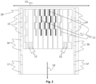
- the varnishes COMP-1 to COMP-4 and INV-1 to INV-6 were printed on a Dibond substrate by a multipass printer Tauro ® H3300 HS from AGFA employing a CMYKLcLk inkset Anuvia ® 1050 from AGFA and a print module (10) as depicted in Figure 2 .
- a test pattern including unprinted areas and areas with text and multicolour graphics, involving also dark green squares of 40 cm x 40 cm was bi-directionally printed by the print heads (11) and simultaneously UV cured by the UV LED modules (15).
- the varnish compositions COMP-1 to COMP-4 and INV-1 to INV-6 were jetted using the print heads (12) and having the UV LED modules (16) turned off. UV curing of the varnish occurred after a delay of about 5 seconds using the UV LED modules (17).
- Table 5 shows the reference signs used in Figures 1 and 2 .
- Table 5 1 Bump 2 Dip 3 First print swath 4 Second print swath 10
- Print module 11 Print head for colour ink 12
- Print head for varnish 13 Scanning direction 14
- Transport direction of substrate 15 UV LED module 16
- UV LED module 17 UV LED module
Landscapes
- Chemical & Material Sciences (AREA)
- Life Sciences & Earth Sciences (AREA)
- Engineering & Computer Science (AREA)
- Materials Engineering (AREA)
- Wood Science & Technology (AREA)
- Organic Chemistry (AREA)
- Inks, Pencil-Leads, Or Crayons (AREA)
- Ink Jet Recording Methods And Recording Media Thereof (AREA)
Claims (15)
- Ein Tintenstrahldruckverfahren, das die folgenden Schritte umfasst:a) Aufsprühen eines Lacks auf ein Substrat, undb) UV-Härtung des Lacks mit UV-LED-Quellen mit einer Spektralemission im Bereich von 360-420 nm nach einer Härtungsverzögerung von mindestens 2 Sekunden,wobei die gemäß dem in der Beschreibung identifizierten Verfahren bestimmte statische Oberflächenspannung des Lacks bei 28 mN/m oder mehr liegt,wobei der Lack mehr als 12 Gew.-% Acylphosphinoxid-Fotoinitiator, bezogen auf das Gesamtgewicht des Lacks, enthält, undwobei die Härtungsverzögerung der Zeitraum zwischen dem Auftreffen eines Lacktröpfchens auf das Substrat und dem Anfang der UV-Härtung ist.
- Das Tintenstrahldruckverfahren nach Anspruch 1, wobei der Lack ein Gemisch aus einem polyfunktionellen Acrylat und einem Methacrylat enthält.
- Das Tintenstrahldruckverfahren nach Anspruch 2, wobei das polyfunktionelle Acrylat ein difunktionelles Acrylat ist.
- Das Tintenstrahldruckverfahren nach einem der Ansprüche 1 bis 3, wobei der Lack eine polymerisierbare Zusammensetzung enthält, die Folgendes enthält:a) 10 Gew.-% bis 30 Gew.-% eines monofunktionellen Methacrylats,b) 40 Gew.-% bis 70 Gew.-% eines polyfunktionellen Acrylats, undc) 0 Gew.-% bis 15 Gew.-% eines monofunktionellen Acrylats, wobei die Gewichtsprozentsätze bezogen auf das Gesamtgewicht des Lacks ausgedrückt sind.
- Das Tintenstrahldruckverfahren nach einem der Ansprüche 1 bis 4, wobei das monofunktionelle Methacrylat einen gemäß dem in der Beschreibung identifizierten Verfahren bestimmten Tg-Wert von mehr als 25°C hat.
- Das Tintenstrahldruckverfahren nach Anspruch 5, wobei das monofunktionelle Methacrylat Isobornylmethacrylat umfasst.
- Das Tintenstrahldruckverfahren nach einem der Ansprüche 1 bis 6, wobei die polymerisierbare Zusammensetzung kein monofunktionelles Acrylat enthält.
- Das Tintenstrahldruckverfahren nach einem der Ansprüche 1 bis 7, wobei der Lack eine Viskosität bei einer Temperatur von 25°C und einer Schergeschwindigkeit von 1.000 s-1 von weniger als 13,0 mPa.s aufweist.
- Das Tintenstrahldruckverfahren nach einem der Ansprüche 1 bis 8, wobei der Acylphosphinoxid-Fotoinitiator ein Acylphosphinoxidinitiator ist, wobei die Acylgruppe aus der Gruppe bestehend aus einer durch eine Harnstoffgruppe, eine Oxalylamidgruppe oder eine polymerisierbare Gruppe substituierten Benzoylgruppe, einer in 3-Stellung durch eine Harnstoffgruppe, eine Oxalylamidgruppe oder eine polymerisierbare Gruppe subsituierten 2,6-Dimethylbenzoylgruppe, einer in 3-Stellung durch eine Harnstoffgruppe, eine Oxalylamidgruppe oder eine polymerisierbare Gruppe subsituierten 2,6-Dimethoxybenzoylgruppe, einer in 3-Stellung durch eine Harnstoffgruppe, eine Oxalylamidgruppe oder eine polymerisierbare Gruppe subsituierten 2,4,6-Trimethylbenzoylgruppe und einer in 3-Stellung durch eine Harnstoffgruppe, eine Oxalylamidgruppe oder eine polymerisierbare Gruppe subsituierten 2,4,6-Trimethoxybenzoylgruppe gewählt wird.
- Das Tintenstrahldruckverfahren nach einem der Ansprüche 1 bis 9, wobei das Substrat ein gedrucktes Bild umfasst.
- Das Tintenstrahldruckverfahren nach Anspruch 10, wobei das gedruckte Bild ein durch Tintenstrahl gedrucktes, durch Tröpfchen einer Farbtinte gebildetes Farbbild ist.
- Das Tintenstrahldruckverfahren nach Anspruch 11, wobei die Tröpfchengröße der die Lackschicht bildenden Tröpfchen und die Tröpfchengröße der das Farbbild bildenden Tröpfchen wesentlich gleich sind.
- Das Tintenstrahldruckverfahren nach Anspruch 11 oder 12, wobei die Schichtdicke der Lackschicht größer ist als die Schichtdicke des Farbbildes.
- Das Tintenstrahldruckverfahren nach einem der Ansprüche 1 bis 13, wobei die gemäß dem in der Beschreibung identifizierten Verfahren bestimmte statische Oberflächenspannung bei mindestens 30 mN/m liegt.
- Ein nach dem Verfahren nach einem der Ansprüche 1 bis 14 hergestelltes lackiertes Substrat, das zur Verwendung als Verpackung oder Innendekoration geeignet ist.
Priority Applications (3)
| Application Number | Priority Date | Filing Date | Title |
|---|---|---|---|
| EP22176388.1A EP4286483B1 (de) | 2022-05-31 | 2022-05-31 | Tintenstrahldruckverfahren |
| PCT/EP2023/057173 WO2023232305A1 (en) | 2022-05-31 | 2023-03-21 | Inkjet printing methods |
| CN202380044112.4A CN119343414A (zh) | 2022-05-31 | 2023-03-21 | 喷墨印刷方法 |
Applications Claiming Priority (1)
| Application Number | Priority Date | Filing Date | Title |
|---|---|---|---|
| EP22176388.1A EP4286483B1 (de) | 2022-05-31 | 2022-05-31 | Tintenstrahldruckverfahren |
Publications (2)
| Publication Number | Publication Date |
|---|---|
| EP4286483A1 EP4286483A1 (de) | 2023-12-06 |
| EP4286483B1 true EP4286483B1 (de) | 2024-10-23 |
Family
ID=81854674
Family Applications (1)
| Application Number | Title | Priority Date | Filing Date |
|---|---|---|---|
| EP22176388.1A Active EP4286483B1 (de) | 2022-05-31 | 2022-05-31 | Tintenstrahldruckverfahren |
Country Status (3)
| Country | Link |
|---|---|
| EP (1) | EP4286483B1 (de) |
| CN (1) | CN119343414A (de) |
| WO (1) | WO2023232305A1 (de) |
Families Citing this family (1)
| Publication number | Priority date | Publication date | Assignee | Title |
|---|---|---|---|---|
| EP4617331A1 (de) | 2024-03-15 | 2025-09-17 | Agfa Nv | Uv-härtbare tintenstrahltinten und tintenstrahldruckverfahren |
Family Cites Families (11)
| Publication number | Priority date | Publication date | Assignee | Title |
|---|---|---|---|---|
| CN1827239A (zh) | 2005-03-04 | 2006-09-06 | 海德堡印刷机械股份公司 | 用于对印刷物喷墨上漆的方法 |
| FR2989688B1 (fr) | 2012-04-24 | 2016-09-30 | Mgi France | Composition de vernis transferable par jet d'encre adapte pour encre sublimable ou de transfert thermique |
| ES2547911T3 (es) | 2012-07-06 | 2015-10-09 | Agfa Graphics Nv | Métodos de barnizado por inyección de tinta |
| JP6293151B2 (ja) | 2012-09-26 | 2018-03-14 | オセ−テクノロジーズ ビーブイ | 硬化性液の適用方法及びその方法を行うための装置 |
| WO2014051026A1 (ja) | 2012-09-27 | 2014-04-03 | 富士フイルム株式会社 | インク組成物、インクジェット記録方法、印刷物、ビスアシルホスフィンオキシド化合物、及び、モノアシルホスフィンオキシド化合物 |
| EP2786878A1 (de) | 2013-04-04 | 2014-10-08 | Hewlett-Packard Industrial Printing Ltd. | Verfahren zum Drucken von Artikeln |
| EP2810783B1 (de) | 2013-06-03 | 2015-10-21 | Hewlett-Packard Industrial Printing Ltd. | Tintenstrahldruckverfahren |
| EP3070130B1 (de) | 2015-03-20 | 2018-01-03 | Agfa Nv | Uv-härtbare farblose tintenstrahlflüssigkeiten |
| US10316206B2 (en) | 2015-09-28 | 2019-06-11 | MGI Digital Technology | Varnish composition with low levels of migration for inkjet-printed substrate |
| US10427442B2 (en) | 2018-01-13 | 2019-10-01 | Great Computer Corporation | Multi-pass UV inkjet printer for outputting high glossy varnish and printing method using the same |
| ES2986615T3 (es) | 2018-06-19 | 2024-11-12 | Agfa Nv | Composiciones curables por radiación uv y procedimientos de impresión por inyección de tinta |
-
2022
- 2022-05-31 EP EP22176388.1A patent/EP4286483B1/de active Active
-
2023
- 2023-03-21 CN CN202380044112.4A patent/CN119343414A/zh active Pending
- 2023-03-21 WO PCT/EP2023/057173 patent/WO2023232305A1/en not_active Ceased
Also Published As
| Publication number | Publication date |
|---|---|
| EP4286483A1 (de) | 2023-12-06 |
| CN119343414A (zh) | 2025-01-21 |
| WO2023232305A1 (en) | 2023-12-07 |
Similar Documents
| Publication | Publication Date | Title |
|---|---|---|
| US11466168B2 (en) | Free radical UV curable inkjet ink sets and inkjet printing methods | |
| US11306215B2 (en) | UV curable inkjet inks | |
| EP3070130B1 (de) | Uv-härtbare farblose tintenstrahlflüssigkeiten | |
| EP2703457B1 (de) | Strahlungshärtbare Tintenstrahltinten mit migrationsarmen freien Radikalen | |
| EP3241874B1 (de) | Acylphosphinoxid-fotoinitiatoren | |
| US9751337B2 (en) | Inkjet printing outdoor graphics | |
| EP3464490B1 (de) | Photoinitiatoren und härtbare zusammensetzungen | |
| US20170342282A1 (en) | Uv curable inkjet inks for printing on glass | |
| EP3034312A1 (de) | Strahlungshärtbare Zusammensetzungen zum Drucken auf Glas | |
| CN111454612A (zh) | 硬化型透明墨水组合物,墨水套件,收容容器,印刷方法 | |
| EP4286483B1 (de) | Tintenstrahldruckverfahren | |
| WO2015169661A1 (en) | Inkjet printing outdoor graphics | |
| US20240254351A1 (en) | UV LED Free Radical Curable Inkjet Inks | |
| EP4617331A1 (de) | Uv-härtbare tintenstrahltinten und tintenstrahldruckverfahren |
Legal Events
| Date | Code | Title | Description |
|---|---|---|---|
| PUAI | Public reference made under article 153(3) epc to a published international application that has entered the european phase |
Free format text: ORIGINAL CODE: 0009012 |
|
| STAA | Information on the status of an ep patent application or granted ep patent |
Free format text: STATUS: THE APPLICATION HAS BEEN PUBLISHED |
|
| AK | Designated contracting states |
Kind code of ref document: A1 Designated state(s): AL AT BE BG CH CY CZ DE DK EE ES FI FR GB GR HR HU IE IS IT LI LT LU LV MC MK MT NL NO PL PT RO RS SE SI SK SM TR |
|
| STAA | Information on the status of an ep patent application or granted ep patent |
Free format text: STATUS: REQUEST FOR EXAMINATION WAS MADE |
|
| 17P | Request for examination filed |
Effective date: 20240606 |
|
| RBV | Designated contracting states (corrected) |
Designated state(s): AL AT BE BG CH CY CZ DE DK EE ES FI FR GB GR HR HU IE IS IT LI LT LU LV MC MK MT NL NO PL PT RO RS SE SI SK SM TR |
|
| GRAP | Despatch of communication of intention to grant a patent |
Free format text: ORIGINAL CODE: EPIDOSNIGR1 |
|
| STAA | Information on the status of an ep patent application or granted ep patent |
Free format text: STATUS: GRANT OF PATENT IS INTENDED |
|
| INTG | Intention to grant announced |
Effective date: 20240807 |
|
| GRAS | Grant fee paid |
Free format text: ORIGINAL CODE: EPIDOSNIGR3 |
|
| GRAA | (expected) grant |
Free format text: ORIGINAL CODE: 0009210 |
|
| STAA | Information on the status of an ep patent application or granted ep patent |
Free format text: STATUS: THE PATENT HAS BEEN GRANTED |
|
| AK | Designated contracting states |
Kind code of ref document: B1 Designated state(s): AL AT BE BG CH CY CZ DE DK EE ES FI FR GB GR HR HU IE IS IT LI LT LU LV MC MK MT NL NO PL PT RO RS SE SI SK SM TR |
|
| REG | Reference to a national code |
Ref country code: GB Ref legal event code: FG4D |
|
| REG | Reference to a national code |
Ref country code: CH Ref legal event code: EP |
|
| REG | Reference to a national code |
Ref country code: DE Ref legal event code: R096 Ref document number: 602022006989 Country of ref document: DE |
|
| REG | Reference to a national code |
Ref country code: IE Ref legal event code: FG4D |
|
| REG | Reference to a national code |
Ref country code: LT Ref legal event code: MG9D |
|
| REG | Reference to a national code |
Ref country code: NL Ref legal event code: MP Effective date: 20241023 |
|
| REG | Reference to a national code |
Ref country code: AT Ref legal event code: MK05 Ref document number: 1734825 Country of ref document: AT Kind code of ref document: T Effective date: 20241023 |
|
| PG25 | Lapsed in a contracting state [announced via postgrant information from national office to epo] |
Ref country code: NL Free format text: LAPSE BECAUSE OF FAILURE TO SUBMIT A TRANSLATION OF THE DESCRIPTION OR TO PAY THE FEE WITHIN THE PRESCRIBED TIME-LIMIT Effective date: 20241023 |
|
| PG25 | Lapsed in a contracting state [announced via postgrant information from national office to epo] |
Ref country code: NL Free format text: LAPSE BECAUSE OF FAILURE TO SUBMIT A TRANSLATION OF THE DESCRIPTION OR TO PAY THE FEE WITHIN THE PRESCRIBED TIME-LIMIT Effective date: 20241023 |
|
| PG25 | Lapsed in a contracting state [announced via postgrant information from national office to epo] |
Ref country code: HR Free format text: LAPSE BECAUSE OF FAILURE TO SUBMIT A TRANSLATION OF THE DESCRIPTION OR TO PAY THE FEE WITHIN THE PRESCRIBED TIME-LIMIT Effective date: 20241023 Ref country code: IS Free format text: LAPSE BECAUSE OF FAILURE TO SUBMIT A TRANSLATION OF THE DESCRIPTION OR TO PAY THE FEE WITHIN THE PRESCRIBED TIME-LIMIT Effective date: 20250223 Ref country code: PT Free format text: LAPSE BECAUSE OF FAILURE TO SUBMIT A TRANSLATION OF THE DESCRIPTION OR TO PAY THE FEE WITHIN THE PRESCRIBED TIME-LIMIT Effective date: 20250224 |
|
| PG25 | Lapsed in a contracting state [announced via postgrant information from national office to epo] |
Ref country code: FI Free format text: LAPSE BECAUSE OF FAILURE TO SUBMIT A TRANSLATION OF THE DESCRIPTION OR TO PAY THE FEE WITHIN THE PRESCRIBED TIME-LIMIT Effective date: 20241023 |
|
| PG25 | Lapsed in a contracting state [announced via postgrant information from national office to epo] |
Ref country code: BG Free format text: LAPSE BECAUSE OF FAILURE TO SUBMIT A TRANSLATION OF THE DESCRIPTION OR TO PAY THE FEE WITHIN THE PRESCRIBED TIME-LIMIT Effective date: 20241023 |
|
| PG25 | Lapsed in a contracting state [announced via postgrant information from national office to epo] |
Ref country code: ES Free format text: LAPSE BECAUSE OF FAILURE TO SUBMIT A TRANSLATION OF THE DESCRIPTION OR TO PAY THE FEE WITHIN THE PRESCRIBED TIME-LIMIT Effective date: 20241023 |
|
| PG25 | Lapsed in a contracting state [announced via postgrant information from national office to epo] |
Ref country code: NO Free format text: LAPSE BECAUSE OF FAILURE TO SUBMIT A TRANSLATION OF THE DESCRIPTION OR TO PAY THE FEE WITHIN THE PRESCRIBED TIME-LIMIT Effective date: 20250123 |
|
| PG25 | Lapsed in a contracting state [announced via postgrant information from national office to epo] |
Ref country code: LV Free format text: LAPSE BECAUSE OF FAILURE TO SUBMIT A TRANSLATION OF THE DESCRIPTION OR TO PAY THE FEE WITHIN THE PRESCRIBED TIME-LIMIT Effective date: 20241023 Ref country code: GR Free format text: LAPSE BECAUSE OF FAILURE TO SUBMIT A TRANSLATION OF THE DESCRIPTION OR TO PAY THE FEE WITHIN THE PRESCRIBED TIME-LIMIT Effective date: 20250124 Ref country code: AT Free format text: LAPSE BECAUSE OF FAILURE TO SUBMIT A TRANSLATION OF THE DESCRIPTION OR TO PAY THE FEE WITHIN THE PRESCRIBED TIME-LIMIT Effective date: 20241023 |
|
| PG25 | Lapsed in a contracting state [announced via postgrant information from national office to epo] |
Ref country code: PL Free format text: LAPSE BECAUSE OF FAILURE TO SUBMIT A TRANSLATION OF THE DESCRIPTION OR TO PAY THE FEE WITHIN THE PRESCRIBED TIME-LIMIT Effective date: 20241023 |
|
| PG25 | Lapsed in a contracting state [announced via postgrant information from national office to epo] |
Ref country code: RS Free format text: LAPSE BECAUSE OF FAILURE TO SUBMIT A TRANSLATION OF THE DESCRIPTION OR TO PAY THE FEE WITHIN THE PRESCRIBED TIME-LIMIT Effective date: 20250123 |
|
| PG25 | Lapsed in a contracting state [announced via postgrant information from national office to epo] |
Ref country code: SM Free format text: LAPSE BECAUSE OF FAILURE TO SUBMIT A TRANSLATION OF THE DESCRIPTION OR TO PAY THE FEE WITHIN THE PRESCRIBED TIME-LIMIT Effective date: 20241023 |
|
| PGFP | Annual fee paid to national office [announced via postgrant information from national office to epo] |
Ref country code: DE Payment date: 20250507 Year of fee payment: 4 |
|
| PG25 | Lapsed in a contracting state [announced via postgrant information from national office to epo] |
Ref country code: DK Free format text: LAPSE BECAUSE OF FAILURE TO SUBMIT A TRANSLATION OF THE DESCRIPTION OR TO PAY THE FEE WITHIN THE PRESCRIBED TIME-LIMIT Effective date: 20241023 |
|
| PGFP | Annual fee paid to national office [announced via postgrant information from national office to epo] |
Ref country code: BE Payment date: 20250505 Year of fee payment: 4 |
|
| PG25 | Lapsed in a contracting state [announced via postgrant information from national office to epo] |
Ref country code: EE Free format text: LAPSE BECAUSE OF FAILURE TO SUBMIT A TRANSLATION OF THE DESCRIPTION OR TO PAY THE FEE WITHIN THE PRESCRIBED TIME-LIMIT Effective date: 20241023 |
|
| PGFP | Annual fee paid to national office [announced via postgrant information from national office to epo] |
Ref country code: FR Payment date: 20250507 Year of fee payment: 4 |
|
| PG25 | Lapsed in a contracting state [announced via postgrant information from national office to epo] |
Ref country code: RO Free format text: LAPSE BECAUSE OF FAILURE TO SUBMIT A TRANSLATION OF THE DESCRIPTION OR TO PAY THE FEE WITHIN THE PRESCRIBED TIME-LIMIT Effective date: 20241023 |
|
| REG | Reference to a national code |
Ref country code: DE Ref legal event code: R097 Ref document number: 602022006989 Country of ref document: DE |
|
| PG25 | Lapsed in a contracting state [announced via postgrant information from national office to epo] |
Ref country code: SK Free format text: LAPSE BECAUSE OF FAILURE TO SUBMIT A TRANSLATION OF THE DESCRIPTION OR TO PAY THE FEE WITHIN THE PRESCRIBED TIME-LIMIT Effective date: 20241023 |
|
| PG25 | Lapsed in a contracting state [announced via postgrant information from national office to epo] |
Ref country code: CZ Free format text: LAPSE BECAUSE OF FAILURE TO SUBMIT A TRANSLATION OF THE DESCRIPTION OR TO PAY THE FEE WITHIN THE PRESCRIBED TIME-LIMIT Effective date: 20241023 |
|
| PG25 | Lapsed in a contracting state [announced via postgrant information from national office to epo] |
Ref country code: IT Free format text: LAPSE BECAUSE OF FAILURE TO SUBMIT A TRANSLATION OF THE DESCRIPTION OR TO PAY THE FEE WITHIN THE PRESCRIBED TIME-LIMIT Effective date: 20241023 |
|
| PLBE | No opposition filed within time limit |
Free format text: ORIGINAL CODE: 0009261 |
|
| STAA | Information on the status of an ep patent application or granted ep patent |
Free format text: STATUS: NO OPPOSITION FILED WITHIN TIME LIMIT |
|
| PG25 | Lapsed in a contracting state [announced via postgrant information from national office to epo] |
Ref country code: SE Free format text: LAPSE BECAUSE OF FAILURE TO SUBMIT A TRANSLATION OF THE DESCRIPTION OR TO PAY THE FEE WITHIN THE PRESCRIBED TIME-LIMIT Effective date: 20241023 |
|
| 26N | No opposition filed |
Effective date: 20250724 |
|
| REG | Reference to a national code |
Ref country code: CH Ref legal event code: H13 Free format text: ST27 STATUS EVENT CODE: U-0-0-H10-H13 (AS PROVIDED BY THE NATIONAL OFFICE) Effective date: 20251223 |
|
| PG25 | Lapsed in a contracting state [announced via postgrant information from national office to epo] |
Ref country code: LU Free format text: LAPSE BECAUSE OF NON-PAYMENT OF DUE FEES Effective date: 20250531 |