EP4286019A1 - Flugzeug mit einer diwasserstofftransportleitung, einem eingrabenkanal dieser transportleitung und einem belüftungssystem des eingrabenkanals - Google Patents
Flugzeug mit einer diwasserstofftransportleitung, einem eingrabenkanal dieser transportleitung und einem belüftungssystem des eingrabenkanals Download PDFInfo
- Publication number
- EP4286019A1 EP4286019A1 EP23174856.7A EP23174856A EP4286019A1 EP 4286019 A1 EP4286019 A1 EP 4286019A1 EP 23174856 A EP23174856 A EP 23174856A EP 4286019 A1 EP4286019 A1 EP 4286019A1
- Authority
- EP
- European Patent Office
- Prior art keywords
- aircraft
- channel
- door
- inlet
- dihydrogen
- Prior art date
- Legal status (The legal status is an assumption and is not a legal conclusion. Google has not performed a legal analysis and makes no representation as to the accuracy of the status listed.)
- Granted
Links
Images




Classifications
-
- B—PERFORMING OPERATIONS; TRANSPORTING
- B64—AIRCRAFT; AVIATION; COSMONAUTICS
- B64D—EQUIPMENT FOR FITTING IN OR TO AIRCRAFT; FLIGHT SUITS; PARACHUTES; ARRANGEMENT OR MOUNTING OF POWER PLANTS OR PROPULSION TRANSMISSIONS IN AIRCRAFT
- B64D37/00—Arrangements in connection with fuel supply for power plant
- B64D37/005—Accessories not provided for in the groups B64D37/02 - B64D37/28
-
- B—PERFORMING OPERATIONS; TRANSPORTING
- B64—AIRCRAFT; AVIATION; COSMONAUTICS
- B64D—EQUIPMENT FOR FITTING IN OR TO AIRCRAFT; FLIGHT SUITS; PARACHUTES; ARRANGEMENT OR MOUNTING OF POWER PLANTS OR PROPULSION TRANSMISSIONS IN AIRCRAFT
- B64D37/00—Arrangements in connection with fuel supply for power plant
- B64D37/30—Fuel systems for specific fuels
-
- B—PERFORMING OPERATIONS; TRANSPORTING
- B64—AIRCRAFT; AVIATION; COSMONAUTICS
- B64D—EQUIPMENT FOR FITTING IN OR TO AIRCRAFT; FLIGHT SUITS; PARACHUTES; ARRANGEMENT OR MOUNTING OF POWER PLANTS OR PROPULSION TRANSMISSIONS IN AIRCRAFT
- B64D37/00—Arrangements in connection with fuel supply for power plant
- B64D37/32—Safety measures not otherwise provided for, e.g. preventing explosive conditions
-
- B—PERFORMING OPERATIONS; TRANSPORTING
- B64—AIRCRAFT; AVIATION; COSMONAUTICS
- B64D—EQUIPMENT FOR FITTING IN OR TO AIRCRAFT; FLIGHT SUITS; PARACHUTES; ARRANGEMENT OR MOUNTING OF POWER PLANTS OR PROPULSION TRANSMISSIONS IN AIRCRAFT
- B64D37/00—Arrangements in connection with fuel supply for power plant
- B64D37/34—Conditioning fuel, e.g. heating
-
- B—PERFORMING OPERATIONS; TRANSPORTING
- B64—AIRCRAFT; AVIATION; COSMONAUTICS
- B64D—EQUIPMENT FOR FITTING IN OR TO AIRCRAFT; FLIGHT SUITS; PARACHUTES; ARRANGEMENT OR MOUNTING OF POWER PLANTS OR PROPULSION TRANSMISSIONS IN AIRCRAFT
- B64D41/00—Power installations for auxiliary purposes
- B64D2041/005—Fuel cells
Definitions
- the present invention relates to the field of aircraft and, in particular, aircraft whose energy source is liquid or gaseous dihydrogen, whether to power a fuel cell or directly the combustion chamber of an engine.
- the present invention thus relates to an aircraft comprising a dihydrogen transport pipe, a burial channel which allows the passage of the transport pipe and a ventilation system for the burial channel.
- dihydrogen As a source of energy in an aircraft.
- the dihydrogen is stored in a tank and a transport pipe ensures the transport of the dihydrogen from the tank to the consumer device, such as for example a fuel cell or the combustion chamber of an engine.
- An object of the present invention is to propose an aircraft comprising a dihydrogen transport pipe, a burial channel which allows the passage of the pipe transport and a ventilation system for the burial channel which ensures ventilation of the burial channel in particular in the event of a dihydrogen leak during the operating phases of the aircraft.
- each door is mounted movable in rotation around a central vertical shaft relative to the door and relative to the entrance
- the operating system is an electric motor whose motor shaft is arranged to rotate the door shaft.
- the junction box has a housing separated from the pipes by a separation floor, the housing is in fluid communication with the upper channels of the channels connected to said junction box and the separation floor is pierced with at least one hole fluidically connected between at least one of the pipes and the housing.
- the air vent comprises a hatch which is mounted movable between a closed position in which it isolates each window from the outside air and an open position in which it retracts to allow free passage of the outside air towards each window, and said aircraft comprises a movement system controlled by the control unit and arranged to move the hatch alternately from the open position to the closed position.
- the hatch is mounted movable in rotation at a front part
- the movement system comprises a base, a slide mounted sliding on the base, a link of which a first end is fixed in an articulated manner to the slide and a second of which end is hingedly attached to the hatch and an actuator controlled by the control unit and arranged to move the slide along the base.
- fans controlled by the control unit are installed in one or more of the intake pipes.
- heating means controlled by the control unit are installed in one or more of the supply pipes.
- FIG. 1 shows an aircraft 100 which has a fuselage 102 on either side of which is fixed a wing 104. Under each wing 104 is fixed at least one propulsion system 106.
- X the longitudinal direction of the aircraft 100
- Y the transverse direction of the aircraft 100 which is horizontal when the aircraft is on the ground
- Z the vertical direction or vertical height when the aircraft is on the ground.
- forward and rear are to be considered in relation to a direction of advancement of the aircraft 100 during the operation of the propulsion systems 106, this direction being represented schematically by the arrow 107.
- each propulsion system 106 comprises an electric motor, a propeller 108 mounted on the motor shaft of said electric motor and a fuel cell which supplies the motor with electricity.
- the fuel cell is supplied with oxygen and hydrogen to produce electricity.
- the propulsion system 106 can take the form of a turbojet whose fuel which is burned in the combustion chamber is dihydrogen.
- the aircraft 100 also includes a dihydrogen tank 110 which is placed here in a rear part of the fuselage, but which could be placed in another part of the aircraft 100.
- the dihydrogen can be liquid or gaseous.
- the aircraft 100 comprises at least one transport pipe 112a-b in which the dihydrogen flows.
- the transport pipes 112a-b are preferably arranged in the upper part of the aircraft 100 and thus extend along the fuselage 102 and the wings 104 in the upper part thereof.
- a transport pipe 112a which extends between the tank 110 and a consumer device (the fuel cell, the turbojet) which consumes the dihydrogen and which ensures the transport of the dihydrogen from the tank 110 to the consumer device
- a transport pipe 112b which extends between the consumer device and the tank 110 and which ensures the transport of the dihydrogen from the consumer device to the tank 110 for example in the case where the consumer device has not consumed all the dihydrogen supplied.
- the two transport pipes constitute two parallel supply lines which transport the dihydrogen to the engines.
- FIG. 2 shows a section of the fuselage 102 with the transport pipes 112a-b and the Fig. 3 shows a section of a wing 104 with transport pipes 112a-b.
- the transport pipes 112a-b are housed in a module fixed outside the skin of the fuselage 102, but they could be integrated directly into the fuselage 102 as is the case on the Fig. 3 for the transport pipes 112a-b circulating along the wing 104 and which are housed here in a box of the wing 104. But the transport pipes 112a-b could also be housed in the leading edge zones or trailing edges because this would be less penalizing in terms of impact on the structure of the wing box 104.
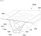
- FIG. 4 shows an enlargement of the Fig. 3 but the description which is made below and which applies to the wing 104 can also apply to the fuselage 102 and the Fig. 5 shows a perspective view of the embodiment of the invention.
- the aircraft 100 For each transport pipe 112a-b, the aircraft 100 includes a burial channel 200a-b in which said transport pipe 112a-b is housed.
- the burial channel 200a-b comprises a channel 202 which has a bottom 203, an opening opposite the bottom 203, and here a cover 204 which covers the opening of the channel 202 by closing it at least in part.
- the transport pipe 112a-b is thus housed between the bottom 203 and the opening and here the cover 204.
- the transport pipe 112a-b is fixed to the channel 202 by any suitable means such as, for example, collars.
- the channel 202 has a trapezoidal section, but sections of different shapes are possible.
- the cover 204 constitutes an exterior wall of the aircraft 100, that is to say it is in direct contact with the exterior air surrounding the aircraft 100.
- the cover 204 is fixed to the exterior wall of the aircraft 100 by any suitable fixing means, such as here bolts 210.
- the cover 204 is pierced with ventilation windows 206 which allow the passage of dihydrogen, in particular in the event of a leak from the transport pipe 112a-b, to the outside, thereby limiting the concentration of dihydrogen in the channel. burial 200a-b and the risks linked to the presence of dihydrogen.
- the cover 204 is in an upper position relative to the bottom 203, that is to say above.
- the dihydrogen is automatically evacuated to the outside and this in a natural manner due to the low density of the gaseous dihydrogen and the presence ventilation windows 206 in the upper part in the cover 204, without it being necessary to install fans and thus provide a simple and light installation.
- direct contact with the moving ambient air makes it possible to limit the spread of the fire by blowing out the flames.
- such an arrangement also makes it possible to confine the flames in the gutter 202 in the event of a fire breaking out and thus to protect the nearby environment.
- each ventilation window 206 is closed by a cap 208 made of a material that breathes dihydrogen, that is to say that the plug 208 is impermeable for external water which cannot penetrate into the burial channel 200a-b, and permeable, among other things for the dihydrogen which is present in the burial channel 200a-b and can be evacuated outwards.
- the cap 208 is made for example of polypropylene or polyethylene.
- each plug 208 is made of a material likely to break under the effect of the heat, such as polypropylene or polyethylene.
- the plug 208 constitutes a fuse which allows the ventilation window 206 to be opened if necessary to blow out the flames.
- the material for the plug 208 is chosen so as to break when the temperature inside the channel 202 reaches a value lower than the maximum temperature acceptable by the channel 202 and the transport pipe 112a-b installed in the channel 202, that is to say the temperature from which the integrity of the channel 202 and the transport pipe 112a-b is no longer guaranteed.
- the cover 204 ruptures under the effect of the overpressure, thus limiting the risk of rupture of the channel 202.
- the tearing resistance of the cover 204 is less than the resistance to the tearing of the channel 202, for example by producing thinner zones.
- the breakage takes place at the level of the means for fixing the cover 204, for example by using fuse bolts which break beyond a certain pressure.
- the gutter 202 is made of a fire-resistant material and more particularly of a material capable of keeping its mechanical properties even in the event of a fire in the gutter 202.
- the material is for example titanium, a titanium alloy or a material comprising a non-fire-resistant core but covered with a fire-resistant protective layer like rock wool or ceramic.
- the gutter 202 comprises at least one low point 212 at the bottom 203 which allows the drainage of the water which would have accumulated in the gutter 202 towards the low point(s) 212.
- the aircraft 100 then comprises for each low point 212, an evacuation pipe 214, a first end of which is fluidly connected to the gutter 202 at the low point 212 and a second end of which opens towards the outside of the aircraft 100 and where the evacuation pipe 214 has a slope descending between the first end and the second end to evacuate the water thus collected by gravity.
- the evacuation pipe 214 makes it possible to evacuate the water and in flight, the pressure difference between the first end and the second end allows additional natural ventilation of the burial channel 200a-b through the windows of ventilation 206 and the plugs 208 when they are present and which will then be preferentially breathable.
- the aircraft 100 comprises an aeration system 600 which is arranged here at the level of the upper part of the aircraft 100 at the level of the junction of the wings 104 and which allows the introduction of outside air and sending this air into each burial channel 200a-b.
- the channel 202 comprises an intermediate floor 520 between the bottom 203 and the opening.
- the intermediate floor 520 is at a distance from the bottom 203 and separates the channel 202 into an upper channel 521 in which the transport pipe 112a-b and a channel are fixed lower 523 in which the air coming from the ventilation system 600 circulates.
- the upper channel 521 extends between the intermediate floor 520 and the cover 204
- the lower channel 523 extends between the bottom 203 and the intermediate floor 520.
- the intermediate floor 520 is perforated and it is here pierced with holes 522 which ensure ventilation of the upper channel 521.
- particular areas require to be particularly ventilated due to the number of elements or connections in this zone and it is then wise to arrange these holes 522 at these zones.
- a zone is for example a zone comprising numerous transport pipes 112a-b, elbows, etc.
- Fig. 6 shows the aeration system 600 according to the invention with the gutters 202 but without the transport pipes 112a-b which reside in said gutters 202.
- the ventilation system 600 comprises an air vent 610 arranged to capture air from outside the aircraft 100 and at least one supply pipe 614 fluidly connected to the air vent 610.
- each supply pipe 614 channels the air taken from the outside at the level of the air vent 610 towards one or more lower gutters 523 of the gutters 202.
- the air vent 610 can alternately take a closed position in Fig. 7 and an open position in Fig. 8 .
- This outer skin 630 can be a skin of the aircraft 100 or an additional skin fixed to the skin of the aircraft 100.
- This outer skin 630 provides an aerodynamic surface limiting energy consumption.
- the air vent 610 includes an air inlet 602 made in the outer skin 630 and at the level of which each intake pipe 614 opens through a window 604 open towards the front of the aircraft 100 in order to capture the air. outside air when the aircraft 100 is moving forward or is stopped.
- the aircraft 100 includes a junction box 601, that is to say at the level of each intersection between an intake pipe 614 and one or more lower gutters 523.
- the junction box 601 is seen in section on the Fig. 9 in view outside the Fig. 10 and comprises for each lower channel 523, an inlet 902 fluidly connected to the supply pipe 614 and an outlet 904 fluidly connected to said lower channel 523, where the inlet 902 and the outlet 904 are fluidly connected to each other by a pipe 905.
- the inlet 902 and the outlet 904 are different for each lower channel 523 and separated from the neighboring inlet 902 by a wall 903.
- the junction box 601 is equipped at the associated inlet 902, with a door 906 movable alternately between an open position where the air is free to circulate between the inlet 902 and the outlet 904 and a closed position in which the air is blocked between the input 902 and the output 904.
- the door 906 is at the input 902, but it can be arranged at the output 904 and in a manner generally, anywhere between the associated input 902 and output 904.
- the junction box 601 includes an operating system controlled by a control unit 50 according to needs as explained below.
- the operating system such as an electric motor 907 is arranged to move said door 906 alternately from the open position to the closed position.
- Each door 906 is here a door mounted movable in rotation around a central vertical shaft relative to the door 906 and relative to the inlet 902 and the motor shaft of the associated motor 907 is here arranged to rotate the door shaft 906.
- the aircraft 100 comprises a detection assembly which comprises a plurality of detection means 52, such as for example dihydrogen detectors 619, which are distributed in each burial channel 200a-b and connected to the control unit 50.
- Each detection means 52 is arranged to detect the presence of dihydrogen and it is arranged to transmit, to the control unit 50, the information according to which it has detected dihydrogen or not.
- the latter will control each operating system 907 to open or close the associated door 906.
- control unit 50 controls the operating system 907 of each door 906 so that said door 906 is in the open position to have similar ventilation towards each lower channel 523.
- the detection assembly when the detection assembly detects a dihydrogen leak at a transport pipe 112a-b, and the aircraft 100 is on the ground, it informs the control unit 50 which controls the operating system 907 of each door 906 corresponding to a lower channel 523 which is not affected by the leak so that said door 906 is in the closed position, and controls the operating system 907 of each corresponding door 906 to a lower gutter 523 affected by the leak so that said door 906 is in the open position to maximize ventilation in said transport pipe 112a-b.
- the junction box 601 has a housing 603 which is separated from the pipes 905 by a separation floor 605.
- the housing 603 is in fluid communication with the upper gutters 521 of the gutters 202 which are connected to said box diversion 601 through their lower gutters 523.
- This housing 603 is arranged to allow the passage of the transport pipe 112a-b which will divide into each gutter 202.
- the separation floor 605 is pierced with at least one hole 607 fluidly connected between at least one of the pipes 905 and the housing 603.
- the air vent 610 includes a hatch 620 which is mounted movable relative to the outer skin 630 between a closed position ( Figs. 6 And 7 ) in which it isolates each window 604 from the outside air (arrow 702) and is continuous with said outer skin 630 and an open position ( Fig. 8 ) in which it retracts to allow free passage of outside air towards each window 604 (arrow 802).
- Each window 604 is arranged in a bowl 606 and the bowl 606 is closed by the hatch 620 or opened when the hatch 620 opens.
- the movement of the hatch 620 is ensured by a movement system 704 which is controlled by the control unit 50 and arranged to move the hatch 620 alternately from the open position to the closed position.
- control unit 50 controls the movement system 704 so as to place the hatch 620 in the open position to ensure a homogeneous air flow in the lower gutters 523, the doors 906 of which are all in the open position.
- the detection assembly when the detection assembly detects a dihydrogen leak at a transport pipe 112a-b and the aircraft 100 is on the ground, it informs the control unit 50 which controls the movement system 704 so as to place the hatch 620 in the open position to ensure air entry and the operating system 907 of each door 906 corresponding to a lower gutter 523 which is not affected by the leak in such a manner so that said door 906 is in the closed position, and controls the operating system 907 of each door 906 corresponding to a lower gutter 523 affected by the leak so that said door 906 is in the open position to maximize ventilation in said transport pipeline 112a-b.
- the unit control 50 controls the movement system 704 so as to place the hatch 620 in the closed position to limit drag and the doors 906 remain in the open position when necessary.
- the detection assembly when the detection assembly detects a dihydrogen leak at a transport pipe 112a-b and the aircraft 100 is in flight, it informs the control unit 50 which controls the movement system 704 so as to place the hatch 620 in the open position to ensure air entry and the operating system 907 of each door 906 corresponding to a lower channel 523 which is not affected by the leak so that said door 906 is in the closed position, and controls the operating system 907 of each door 906 corresponding to a lower gutter 523 affected by the leak so that said door 906 is in the open position to maximize the ventilation in said transport pipeline 112a-b.
- fans 650 are installed in one or more of the intake pipes 614 and these fans 650 are controlled by the control unit 50 to increase the air flow and thus resolve any problems due to leaks more quickly.
- heating means 652 such as for example a heating resistor, installed in one or more of the intake pipes 614 and controlled by the control unit 50.
- the hatch 620 is mounted movable in rotation at a front part around a hinge axis 706 which is parallel to the transverse direction Y.
- the hatch 620 In the closed position, the hatch 620 is raised so as to position itself in front of the windows 604 and close them and in the open position, the hatch 620 is lowered so as to clear the windows 604.
- the movement system 704 is here arranged under the hatch 620 and comprises a base 708 fixed to the structure of the aircraft 100, a slide 710 mounted sliding on the base 708, here parallel to the longitudinal direction first end is hingedly fixed to the slide 710 and a second end of which is hingedly fixed to the hatch 620 and an actuator 714 controlled by the control unit 50 and arranged to move the slide 710 along the base 708.
- the lever 712 will rise or lower, bringing at the same time the hatch 620.
- the actuator 714 is for example a cylinder.
- the translation guidance of the slide 710 on the base 708 is carried out using known means such as for example a slide connection of the groove and T-rail type.
- the intake network 612 is made up of several intake pipes 614 which merge and separate several times to create different paths that the air can take.
- control unit 50 comprises connected by a communication bus: a processor or CPU (“Central Processing Unit” in English); RAM (“Random Access Memory” in English); a ROM (“Read Only Memory” in English); a storage unit such as a hard drive or a storage media reader, such as an SD card reader (“Secure Digital” in English); at least one communication interface, allowing for example the control unit 50 to communicate with the sensors and the motors.
- a communication bus a processor or CPU (“Central Processing Unit” in English); RAM (“Random Access Memory” in English); a ROM (“Read Only Memory” in English); a storage unit such as a hard drive or a storage media reader, such as an SD card reader (“Secure Digital” in English); at least one communication interface, allowing for example the control unit 50 to communicate with the sensors and the motors.
- a communication bus a processor or CPU (“Central Processing Unit” in English); RAM (“Random Access Memory” in English); a ROM (“Read Only Memory” in English); a storage unit such as a hard
- the processor is capable of executing instructions loaded into RAM from ROM, external memory (not shown), storage media (such as an SD card), or an array of communication. When the equipment is powered on, the processor is able to read instructions from RAM and execute them. These instructions form a computer program causing the implementation, by the processor, of all or part of the algorithms and steps described here.
- All or part of the algorithms and steps described below can be implemented in software form by execution of a set of instructions by a programmable machine, for example a DSP (“Digital Signal Processor” in English) or a microcontroller, or be implemented in hardware form by a machine or a dedicated component, for example an FPGA (“Field-Programmable Gate Array” in English) or an ASIC (“Application-Specific Integrated Circuit” in English).
- a programmable machine for example a DSP (“Digital Signal Processor” in English) or a microcontroller
- FPGA Field-Programmable Gate Array
- ASIC Application-Specific Integrated Circuit
Landscapes
- Engineering & Computer Science (AREA)
- Aviation & Aerospace Engineering (AREA)
- Ventilation (AREA)
- Pipeline Systems (AREA)
Applications Claiming Priority (1)
| Application Number | Priority Date | Filing Date | Title |
|---|---|---|---|
| FR2205188A FR3135968A1 (fr) | 2022-05-31 | 2022-05-31 | Aéronef comportant une canalisation de transport de dihydrogène, un canal d’enfouissement de ladite canalisation de transport et un système d’aération dudit canal d’enfouissement |
Publications (2)
| Publication Number | Publication Date |
|---|---|
| EP4286019A1 true EP4286019A1 (de) | 2023-12-06 |
| EP4286019B1 EP4286019B1 (de) | 2025-03-19 |
Family
ID=82319909
Family Applications (1)
| Application Number | Title | Priority Date | Filing Date |
|---|---|---|---|
| EP23174856.7A Active EP4286019B1 (de) | 2022-05-31 | 2023-05-23 | Flugzeug mit einer diwasserstofftransportleitung, einem eingrabenkanal dieser transportleitung und einem belüftungssystem des eingrabenkanals |
Country Status (4)
| Country | Link |
|---|---|
| US (1) | US12459663B2 (de) |
| EP (1) | EP4286019B1 (de) |
| CN (1) | CN117141723A (de) |
| FR (1) | FR3135968A1 (de) |
Families Citing this family (1)
| Publication number | Priority date | Publication date | Assignee | Title |
|---|---|---|---|---|
| EP4691906A1 (de) | 2024-08-07 | 2026-02-11 | AIRBUS Operations GmbH | Wasserstoffbetriebenes flugzeug mit antenne für satelliten-internetzugang |
Citations (3)
| Publication number | Priority date | Publication date | Assignee | Title |
|---|---|---|---|---|
| US20140023479A1 (en) * | 2011-03-25 | 2014-01-23 | Airbus Operations Gmbh | Aircraft tail region with a cooling system installed in aircraft tail region |
| EP3012189A1 (de) * | 2014-10-22 | 2016-04-27 | Airbus Operations GmbH | Bordküchensystem, Verfahren zum Betreiben elektrischer Bordküchenvorrichtungen und Verwendung einer Brennstoffzelle in einem Bordküchensystem |
| US20210078702A1 (en) * | 2019-09-16 | 2021-03-18 | Airbus Operations Sas | Aircraft having support stays for wings in which hydrogen pipes or electrical conductors are arranged |
Family Cites Families (3)
| Publication number | Priority date | Publication date | Assignee | Title |
|---|---|---|---|---|
| DE502006008159D1 (de) * | 2005-03-24 | 2010-12-09 | Ems Chemie Ag | Verwendung eines Leitungssystems für Fluide mit flüchtigen Bestandteilen |
| EP3086011B1 (de) * | 2015-04-21 | 2019-07-31 | Airbus Operations GmbH | Doppelwandiges rohr mit integrierter heizfähigkeit für ein luft- oder raumfahrzeug |
| JP2017165242A (ja) * | 2016-03-16 | 2017-09-21 | 三菱航空機株式会社 | 航空機の燃料配管および航空機 |
-
2022
- 2022-05-31 FR FR2205188A patent/FR3135968A1/fr not_active Ceased
-
2023
- 2023-05-23 EP EP23174856.7A patent/EP4286019B1/de active Active
- 2023-05-30 CN CN202310628097.XA patent/CN117141723A/zh active Pending
- 2023-05-30 US US18/325,217 patent/US12459663B2/en active Active
Patent Citations (3)
| Publication number | Priority date | Publication date | Assignee | Title |
|---|---|---|---|---|
| US20140023479A1 (en) * | 2011-03-25 | 2014-01-23 | Airbus Operations Gmbh | Aircraft tail region with a cooling system installed in aircraft tail region |
| EP3012189A1 (de) * | 2014-10-22 | 2016-04-27 | Airbus Operations GmbH | Bordküchensystem, Verfahren zum Betreiben elektrischer Bordküchenvorrichtungen und Verwendung einer Brennstoffzelle in einem Bordküchensystem |
| US20210078702A1 (en) * | 2019-09-16 | 2021-03-18 | Airbus Operations Sas | Aircraft having support stays for wings in which hydrogen pipes or electrical conductors are arranged |
Also Published As
| Publication number | Publication date |
|---|---|
| CN117141723A (zh) | 2023-12-01 |
| FR3135968A1 (fr) | 2023-12-01 |
| US20230382551A1 (en) | 2023-11-30 |
| EP4286019B1 (de) | 2025-03-19 |
| US12459663B2 (en) | 2025-11-04 |
Similar Documents
| Publication | Publication Date | Title |
|---|---|---|
| EP4155213B1 (de) | Flugzeug mit einer diwasserstofftransportleitung und einem eingrabenkanal der besagten transportleitung | |
| CA2929951C (fr) | Ensemble propulsif d'aeronef avec systeme d'extinction de feu | |
| EP3199206B1 (de) | Prüfstand für triebwerk eines luftfahrzeugs | |
| EP4286019B1 (de) | Flugzeug mit einer diwasserstofftransportleitung, einem eingrabenkanal dieser transportleitung und einem belüftungssystem des eingrabenkanals | |
| EP3085419B1 (de) | Prüfbank für turboreaktor eines luftfahrzeugs mit obturatoren | |
| EP4124738B1 (de) | Antriebsanordnung für luftfahrzeug | |
| CA2742748A1 (fr) | Trappe de surpression destinee a etre montee sur une paroi d'une nacelle pour turboreacteur | |
| FR2977567A1 (fr) | Procede de refroidissement d'un plancher de protection thermique d'un carenage aerodynamique arriere d'un mat d'accrochage d'un ensemble propulsif d'aeronef | |
| FR3013682A1 (de) | ||
| EP0918149B1 (de) | Schutzeinrichtung für den mit einem Enteisungssystem versehenen Lufteinlauf eines Strahltriebwerks | |
| EP4030043B1 (de) | Antriebseinheit für luftfahrzeug, die ein belüftungssystem und ein brandschutzsystem umfasst | |
| EP4371885B1 (de) | Flugzeug mit einem wasserstoffversorgungssystem | |
| FR3094892A1 (fr) | Systeme anti-incendie pour un aeronef comportant un reservoir a double chambre | |
| EP4438487B1 (de) | Flugzeug mit einer diwasserstofftransportleitung, einem eingrabenkanal dieser transportleitung und einem system zur luft- und wasserabführung in diesem eingrabenkanal | |
| EP4455022A1 (de) | Flugzeug mit einer rohrleitung zum transport von diwasserstoff und einem system zur extraktion von diesem wasserstoff nach aussen | |
| EP4495008B1 (de) | Flugzeuggondel mit einem abgedichteten gehäuse und einer tür, die das gehäuse nach aussen öffnet | |
| EP4311778A1 (de) | System zur versorgung eines flugzeugmotors mit diwasserstoff | |
| EP4435316B1 (de) | Modul für ein diwasserstoff-versorgungssystem für einen flugzeugmotor | |
| FR3158953A1 (fr) | Ensemble propulsif pour aéronef comportant un ventilateur d’extraction | |
| EP4293212B1 (de) | Gehäusesystem mit wärmetauscher zur erwärmung von dihydrogen | |
| EP4345009B1 (de) | Antriebseinheit für ein flugzeug | |
| EP3868649B1 (de) | Luftfahrzeug, das mit einem boden und einer brandschutz- und/oder rauchschutz-klappe ausgestattet ist | |
| EP4474288B1 (de) | Flugzeug mit regenschutzentlüftung für eine elektrische maschine | |
| FR3151299A1 (fr) | Ensemble propulsif pour aéronef | |
| FR2972359A1 (fr) | Dispositif de protection de biens immobiliers vis-a-vis d'un incendie dont l'origine est exterieure, quelles que soient la force et la direction du vent |
Legal Events
| Date | Code | Title | Description |
|---|---|---|---|
| PUAI | Public reference made under article 153(3) epc to a published international application that has entered the european phase |
Free format text: ORIGINAL CODE: 0009012 |
|
| STAA | Information on the status of an ep patent application or granted ep patent |
Free format text: STATUS: THE APPLICATION HAS BEEN PUBLISHED |
|
| AK | Designated contracting states |
Kind code of ref document: A1 Designated state(s): AL AT BE BG CH CY CZ DE DK EE ES FI FR GB GR HR HU IE IS IT LI LT LU LV MC ME MK MT NL NO PL PT RO RS SE SI SK SM TR |
|
| STAA | Information on the status of an ep patent application or granted ep patent |
Free format text: STATUS: REQUEST FOR EXAMINATION WAS MADE |
|
| 17P | Request for examination filed |
Effective date: 20240605 |
|
| RBV | Designated contracting states (corrected) |
Designated state(s): AL AT BE BG CH CY CZ DE DK EE ES FI FR GB GR HR HU IE IS IT LI LT LU LV MC ME MK MT NL NO PL PT RO RS SE SI SK SM TR |
|
| GRAP | Despatch of communication of intention to grant a patent |
Free format text: ORIGINAL CODE: EPIDOSNIGR1 |
|
| STAA | Information on the status of an ep patent application or granted ep patent |
Free format text: STATUS: GRANT OF PATENT IS INTENDED |
|
| RIC1 | Information provided on ipc code assigned before grant |
Ipc: A62C 3/08 20060101AFI20241001BHEP |
|
| INTG | Intention to grant announced |
Effective date: 20241015 |
|
| GRAS | Grant fee paid |
Free format text: ORIGINAL CODE: EPIDOSNIGR3 |
|
| GRAA | (expected) grant |
Free format text: ORIGINAL CODE: 0009210 |
|
| STAA | Information on the status of an ep patent application or granted ep patent |
Free format text: STATUS: THE PATENT HAS BEEN GRANTED |
|
| AK | Designated contracting states |
Kind code of ref document: B1 Designated state(s): AL AT BE BG CH CY CZ DE DK EE ES FI FR GB GR HR HU IE IS IT LI LT LU LV MC ME MK MT NL NO PL PT RO RS SE SI SK SM TR |
|
| REG | Reference to a national code |
Ref country code: GB Ref legal event code: FG4D Free format text: NOT ENGLISH |
|
| REG | Reference to a national code |
Ref country code: CH Ref legal event code: EP |
|
| REG | Reference to a national code |
Ref country code: DE Ref legal event code: R096 Ref document number: 602023002447 Country of ref document: DE |
|
| REG | Reference to a national code |
Ref country code: IE Ref legal event code: FG4D Free format text: LANGUAGE OF EP DOCUMENT: FRENCH |
|
| PG25 | Lapsed in a contracting state [announced via postgrant information from national office to epo] |
Ref country code: RS Free format text: LAPSE BECAUSE OF FAILURE TO SUBMIT A TRANSLATION OF THE DESCRIPTION OR TO PAY THE FEE WITHIN THE PRESCRIBED TIME-LIMIT Effective date: 20250619 |
|
| PG25 | Lapsed in a contracting state [announced via postgrant information from national office to epo] |
Ref country code: FI Free format text: LAPSE BECAUSE OF FAILURE TO SUBMIT A TRANSLATION OF THE DESCRIPTION OR TO PAY THE FEE WITHIN THE PRESCRIBED TIME-LIMIT Effective date: 20250319 |
|
| PGFP | Annual fee paid to national office [announced via postgrant information from national office to epo] |
Ref country code: DE Payment date: 20250521 Year of fee payment: 3 |
|
| REG | Reference to a national code |
Ref country code: LT Ref legal event code: MG9D |
|
| PG25 | Lapsed in a contracting state [announced via postgrant information from national office to epo] |
Ref country code: NO Free format text: LAPSE BECAUSE OF FAILURE TO SUBMIT A TRANSLATION OF THE DESCRIPTION OR TO PAY THE FEE WITHIN THE PRESCRIBED TIME-LIMIT Effective date: 20250619 |
|
| PG25 | Lapsed in a contracting state [announced via postgrant information from national office to epo] |
Ref country code: HR Free format text: LAPSE BECAUSE OF FAILURE TO SUBMIT A TRANSLATION OF THE DESCRIPTION OR TO PAY THE FEE WITHIN THE PRESCRIBED TIME-LIMIT Effective date: 20250319 |
|
| PG25 | Lapsed in a contracting state [announced via postgrant information from national office to epo] |
Ref country code: LV Free format text: LAPSE BECAUSE OF FAILURE TO SUBMIT A TRANSLATION OF THE DESCRIPTION OR TO PAY THE FEE WITHIN THE PRESCRIBED TIME-LIMIT Effective date: 20250319 |
|
| PGFP | Annual fee paid to national office [announced via postgrant information from national office to epo] |
Ref country code: FR Payment date: 20250528 Year of fee payment: 3 |
|
| PG25 | Lapsed in a contracting state [announced via postgrant information from national office to epo] |
Ref country code: BG Free format text: LAPSE BECAUSE OF FAILURE TO SUBMIT A TRANSLATION OF THE DESCRIPTION OR TO PAY THE FEE WITHIN THE PRESCRIBED TIME-LIMIT Effective date: 20250319 Ref country code: GR Free format text: LAPSE BECAUSE OF FAILURE TO SUBMIT A TRANSLATION OF THE DESCRIPTION OR TO PAY THE FEE WITHIN THE PRESCRIBED TIME-LIMIT Effective date: 20250620 |
|
| REG | Reference to a national code |
Ref country code: NL Ref legal event code: MP Effective date: 20250319 |
|
| REG | Reference to a national code |
Ref country code: AT Ref legal event code: MK05 Ref document number: 1776490 Country of ref document: AT Kind code of ref document: T Effective date: 20250319 |
|
| PG25 | Lapsed in a contracting state [announced via postgrant information from national office to epo] |
Ref country code: NL Free format text: LAPSE BECAUSE OF FAILURE TO SUBMIT A TRANSLATION OF THE DESCRIPTION OR TO PAY THE FEE WITHIN THE PRESCRIBED TIME-LIMIT Effective date: 20250319 |
|
| PG25 | Lapsed in a contracting state [announced via postgrant information from national office to epo] |
Ref country code: SE Free format text: LAPSE BECAUSE OF FAILURE TO SUBMIT A TRANSLATION OF THE DESCRIPTION OR TO PAY THE FEE WITHIN THE PRESCRIBED TIME-LIMIT Effective date: 20250319 |
|
| PG25 | Lapsed in a contracting state [announced via postgrant information from national office to epo] |
Ref country code: SM Free format text: LAPSE BECAUSE OF FAILURE TO SUBMIT A TRANSLATION OF THE DESCRIPTION OR TO PAY THE FEE WITHIN THE PRESCRIBED TIME-LIMIT Effective date: 20250319 |
|
| PG25 | Lapsed in a contracting state [announced via postgrant information from national office to epo] |
Ref country code: ES Free format text: LAPSE BECAUSE OF FAILURE TO SUBMIT A TRANSLATION OF THE DESCRIPTION OR TO PAY THE FEE WITHIN THE PRESCRIBED TIME-LIMIT Effective date: 20250319 Ref country code: PT Free format text: LAPSE BECAUSE OF FAILURE TO SUBMIT A TRANSLATION OF THE DESCRIPTION OR TO PAY THE FEE WITHIN THE PRESCRIBED TIME-LIMIT Effective date: 20250721 |
|
| PG25 | Lapsed in a contracting state [announced via postgrant information from national office to epo] |
Ref country code: IT Free format text: LAPSE BECAUSE OF FAILURE TO SUBMIT A TRANSLATION OF THE DESCRIPTION OR TO PAY THE FEE WITHIN THE PRESCRIBED TIME-LIMIT Effective date: 20250319 Ref country code: PL Free format text: LAPSE BECAUSE OF FAILURE TO SUBMIT A TRANSLATION OF THE DESCRIPTION OR TO PAY THE FEE WITHIN THE PRESCRIBED TIME-LIMIT Effective date: 20250319 |
|
| PG25 | Lapsed in a contracting state [announced via postgrant information from national office to epo] |
Ref country code: AT Free format text: LAPSE BECAUSE OF FAILURE TO SUBMIT A TRANSLATION OF THE DESCRIPTION OR TO PAY THE FEE WITHIN THE PRESCRIBED TIME-LIMIT Effective date: 20250319 |
|
| PG25 | Lapsed in a contracting state [announced via postgrant information from national office to epo] |
Ref country code: EE Free format text: LAPSE BECAUSE OF FAILURE TO SUBMIT A TRANSLATION OF THE DESCRIPTION OR TO PAY THE FEE WITHIN THE PRESCRIBED TIME-LIMIT Effective date: 20250319 Ref country code: CZ Free format text: LAPSE BECAUSE OF FAILURE TO SUBMIT A TRANSLATION OF THE DESCRIPTION OR TO PAY THE FEE WITHIN THE PRESCRIBED TIME-LIMIT Effective date: 20250319 |
|
| PG25 | Lapsed in a contracting state [announced via postgrant information from national office to epo] |
Ref country code: RO Free format text: LAPSE BECAUSE OF FAILURE TO SUBMIT A TRANSLATION OF THE DESCRIPTION OR TO PAY THE FEE WITHIN THE PRESCRIBED TIME-LIMIT Effective date: 20250319 |
|
| PG25 | Lapsed in a contracting state [announced via postgrant information from national office to epo] |
Ref country code: SK Free format text: LAPSE BECAUSE OF FAILURE TO SUBMIT A TRANSLATION OF THE DESCRIPTION OR TO PAY THE FEE WITHIN THE PRESCRIBED TIME-LIMIT Effective date: 20250319 |
|
| PG25 | Lapsed in a contracting state [announced via postgrant information from national office to epo] |
Ref country code: IS Free format text: LAPSE BECAUSE OF FAILURE TO SUBMIT A TRANSLATION OF THE DESCRIPTION OR TO PAY THE FEE WITHIN THE PRESCRIBED TIME-LIMIT Effective date: 20250719 |
|
| REG | Reference to a national code |
Ref country code: DE Ref legal event code: R097 Ref document number: 602023002447 Country of ref document: DE |
|
| PG25 | Lapsed in a contracting state [announced via postgrant information from national office to epo] |
Ref country code: DK Free format text: LAPSE BECAUSE OF FAILURE TO SUBMIT A TRANSLATION OF THE DESCRIPTION OR TO PAY THE FEE WITHIN THE PRESCRIBED TIME-LIMIT Effective date: 20250319 |
|
| PG25 | Lapsed in a contracting state [announced via postgrant information from national office to epo] |
Ref country code: LU Free format text: LAPSE BECAUSE OF NON-PAYMENT OF DUE FEES Effective date: 20250523 |
|
| PLBE | No opposition filed within time limit |
Free format text: ORIGINAL CODE: 0009261 |
|
| STAA | Information on the status of an ep patent application or granted ep patent |
Free format text: STATUS: NO OPPOSITION FILED WITHIN TIME LIMIT |
|
| REG | Reference to a national code |
Ref country code: CH Ref legal event code: L10 Free format text: ST27 STATUS EVENT CODE: U-0-0-L10-L00 (AS PROVIDED BY THE NATIONAL OFFICE) Effective date: 20260128 |
|
| REG | Reference to a national code |
Ref country code: BE Ref legal event code: MM Effective date: 20250531 |
|
| PG25 | Lapsed in a contracting state [announced via postgrant information from national office to epo] |
Ref country code: MC Free format text: LAPSE BECAUSE OF FAILURE TO SUBMIT A TRANSLATION OF THE DESCRIPTION OR TO PAY THE FEE WITHIN THE PRESCRIBED TIME-LIMIT Effective date: 20250319 |
|
| 26N | No opposition filed |
Effective date: 20251222 |
|
| PG25 | Lapsed in a contracting state [announced via postgrant information from national office to epo] |
Ref country code: IE Free format text: LAPSE BECAUSE OF NON-PAYMENT OF DUE FEES Effective date: 20250523 |
|
| PG25 | Lapsed in a contracting state [announced via postgrant information from national office to epo] |
Ref country code: BE Free format text: LAPSE BECAUSE OF NON-PAYMENT OF DUE FEES Effective date: 20250531 |