EP4285090B1 - Electronic strut monitor - Google Patents
Electronic strut monitor Download PDFInfo
- Publication number
- EP4285090B1 EP4285090B1 EP22704268.6A EP22704268A EP4285090B1 EP 4285090 B1 EP4285090 B1 EP 4285090B1 EP 22704268 A EP22704268 A EP 22704268A EP 4285090 B1 EP4285090 B1 EP 4285090B1
- Authority
- EP
- European Patent Office
- Prior art keywords
- monitor
- housing
- monitoring device
- coupling mechanism
- strut
- Prior art date
- Legal status (The legal status is an assumption and is not a legal conclusion. Google has not performed a legal analysis and makes no representation as to the accuracy of the status listed.)
- Active
Links
Images


Classifications
-
- G—PHYSICS
- G06—COMPUTING OR CALCULATING; COUNTING
- G06K—GRAPHICAL DATA READING; PRESENTATION OF DATA; RECORD CARRIERS; HANDLING RECORD CARRIERS
- G06K7/00—Methods or arrangements for sensing record carriers, e.g. for reading patterns
- G06K7/10—Methods or arrangements for sensing record carriers, e.g. for reading patterns by electromagnetic radiation, e.g. optical sensing; by corpuscular radiation
- G06K7/10009—Methods or arrangements for sensing record carriers, e.g. for reading patterns by electromagnetic radiation, e.g. optical sensing; by corpuscular radiation sensing by radiation using wavelengths larger than 0.1 mm, e.g. radio-waves or microwaves
- G06K7/10366—Methods or arrangements for sensing record carriers, e.g. for reading patterns by electromagnetic radiation, e.g. optical sensing; by corpuscular radiation sensing by radiation using wavelengths larger than 0.1 mm, e.g. radio-waves or microwaves the interrogation device being adapted for miscellaneous applications
-
- E—FIXED CONSTRUCTIONS
- E04—BUILDING
- E04G—SCAFFOLDING; FORMS; SHUTTERING; BUILDING IMPLEMENTS OR AIDS, OR THEIR USE; HANDLING BUILDING MATERIALS ON THE SITE; REPAIRING, BREAKING-UP OR OTHER WORK ON EXISTING BUILDINGS
- E04G25/00—Shores or struts; Chocks
- E04G25/04—Shores or struts; Chocks telescopic
-
- G—PHYSICS
- G01—MEASURING; TESTING
- G01C—MEASURING DISTANCES, LEVELS OR BEARINGS; SURVEYING; NAVIGATION; GYROSCOPIC INSTRUMENTS; PHOTOGRAMMETRY OR VIDEOGRAMMETRY
- G01C9/00—Measuring inclination, e.g. by clinometers, by levels
- G01C9/02—Details
- G01C9/04—Transmission means between sensing element and final indicator for giving an enlarged reading
-
- G—PHYSICS
- G01—MEASURING; TESTING
- G01H—MEASUREMENT OF MECHANICAL VIBRATIONS OR ULTRASONIC, SONIC OR INFRASONIC WAVES
- G01H1/00—Measuring characteristics of vibrations in solids by using direct conduction to the detector
-
- G—PHYSICS
- G01—MEASURING; TESTING
- G01L—MEASURING FORCE, STRESS, TORQUE, WORK, MECHANICAL POWER, MECHANICAL EFFICIENCY, OR FLUID PRESSURE
- G01L1/00—Measuring force or stress, in general
- G01L1/005—Measuring force or stress, in general by electrical means and not provided for in G01L1/06 - G01L1/22
-
- G—PHYSICS
- G01—MEASURING; TESTING
- G01M—TESTING STATIC OR DYNAMIC BALANCE OF MACHINES OR STRUCTURES; TESTING OF STRUCTURES OR APPARATUS, NOT OTHERWISE PROVIDED FOR
- G01M5/00—Investigating the elasticity of structures, e.g. deflection of bridges or air-craft wings
- G01M5/0041—Investigating the elasticity of structures, e.g. deflection of bridges or air-craft wings by determining deflection or stress
- G01M5/005—Investigating the elasticity of structures, e.g. deflection of bridges or air-craft wings by determining deflection or stress by means of external apparatus, e.g. test benches or portable test systems
- G01M5/0058—Investigating the elasticity of structures, e.g. deflection of bridges or air-craft wings by determining deflection or stress by means of external apparatus, e.g. test benches or portable test systems of elongated objects, e.g. pipes, masts, towers or railways
-
- G—PHYSICS
- G01—MEASURING; TESTING
- G01M—TESTING STATIC OR DYNAMIC BALANCE OF MACHINES OR STRUCTURES; TESTING OF STRUCTURES OR APPARATUS, NOT OTHERWISE PROVIDED FOR
- G01M5/00—Investigating the elasticity of structures, e.g. deflection of bridges or air-craft wings
- G01M5/0066—Investigating the elasticity of structures, e.g. deflection of bridges or air-craft wings by exciting or detecting vibration or acceleration
-
- G—PHYSICS
- G06—COMPUTING OR CALCULATING; COUNTING
- G06K—GRAPHICAL DATA READING; PRESENTATION OF DATA; RECORD CARRIERS; HANDLING RECORD CARRIERS
- G06K19/00—Record carriers for use with machines and with at least a part designed to carry digital markings
- G06K19/06—Record carriers for use with machines and with at least a part designed to carry digital markings characterised by the kind of the digital marking, e.g. shape, nature, code
- G06K19/067—Record carriers with conductive marks, printed circuits or semiconductor circuit elements, e.g. credit or identity cards also with resonating or responding marks without active components
- G06K19/07—Record carriers with conductive marks, printed circuits or semiconductor circuit elements, e.g. credit or identity cards also with resonating or responding marks without active components with integrated circuit chips
- G06K19/077—Constructional details, e.g. mounting of circuits in the carrier
- G06K19/07749—Constructional details, e.g. mounting of circuits in the carrier the record carrier being capable of non-contact communication, e.g. constructional details of the antenna of a non-contact smart card
- G06K19/07758—Constructional details, e.g. mounting of circuits in the carrier the record carrier being capable of non-contact communication, e.g. constructional details of the antenna of a non-contact smart card arrangements for adhering the record carrier to further objects or living beings, functioning as an identification tag
-
- G—PHYSICS
- G06—COMPUTING OR CALCULATING; COUNTING
- G06Q—INFORMATION AND COMMUNICATION TECHNOLOGY [ICT] SPECIALLY ADAPTED FOR ADMINISTRATIVE, COMMERCIAL, FINANCIAL, MANAGERIAL OR SUPERVISORY PURPOSES; SYSTEMS OR METHODS SPECIALLY ADAPTED FOR ADMINISTRATIVE, COMMERCIAL, FINANCIAL, MANAGERIAL OR SUPERVISORY PURPOSES, NOT OTHERWISE PROVIDED FOR
- G06Q50/00—Information and communication technology [ICT] specially adapted for implementation of business processes of specific business sectors, e.g. utilities or tourism
- G06Q50/10—Services
-
- G—PHYSICS
- G08—SIGNALLING
- G08B—SIGNALLING SYSTEMS, e.g. PERSONAL CALLING SYSTEMS; ORDER TELEGRAPHS; ALARM SYSTEMS
- G08B21/00—Alarms responsive to a single specified undesired or abnormal condition and not otherwise provided for
- G08B21/18—Status alarms
-
- G—PHYSICS
- G08—SIGNALLING
- G08B—SIGNALLING SYSTEMS, e.g. PERSONAL CALLING SYSTEMS; ORDER TELEGRAPHS; ALARM SYSTEMS
- G08B21/00—Alarms responsive to a single specified undesired or abnormal condition and not otherwise provided for
- G08B21/18—Status alarms
- G08B21/182—Level alarms, e.g. alarms responsive to variables exceeding a threshold
-
- G—PHYSICS
- G08—SIGNALLING
- G08C—TRANSMISSION SYSTEMS FOR MEASURED VALUES, CONTROL OR SIMILAR SIGNALS
- G08C17/00—Arrangements for transmitting signals characterised by the use of a wireless electrical link
- G08C17/02—Arrangements for transmitting signals characterised by the use of a wireless electrical link using a radio link
Definitions
- a strut may be utilized to brace an unstable structure.
- one or more struts may be positioned to brace an unstable structure of a vehicle following an accident.
- one or more struts may be positioned to reinforce damaged structures within a ship, such as bulkheads, sections of a hull, or hatches.
- one or more struts may be positioned to bear part, or all, of a weight of a wall, a ceiling, or a roof of an unstable structure.
- a strut may be utilized by emergency services, or other users, in time-sensitive situations and/or situations in which the types of on-hand materials are limited, and in which there is a possibility of/ there has been structural failure of load-bearing elements.
- CN 108 798 068 A describes a safe supporting system suitable for fabricated building and bridge construction.
- the safe supporting system comprises a lower supporting pipe, an upper supporting pipe and an adjusting supporting pipe; a first through groove penetrating in the front-rear direction is formed in the lower end of the main support.
- US 2020/299983 A1 describes a strut which includes a first post section and a second post section.
- the first post section includes a first portion that is coaxial with, annular to and slidably disposed within a second portion of the second post section.
- a damping actuator is interposed between the first post section and the second post section, and is arranged to dynamically control a position of the first post section in relation to the second post section.
- US 2015/144762 A1 describes a system for adjustable construction or demolition temporary supports.
- the adjustable construction or demolition temporary support includes a plurality of sensor devices for measuring load on the support and signal detection and communication device that being in communication with the sensor devices.
- the communication device further comprises a display unit and/or audio output unit for providing visual and/or audible alarm for alarming conditions.
- US 2015/308474 A1 describes a shaft adapter configured to be removably-coupled to shafts of differing diameters.
- the shaft adapter may have a stepped cylinder cavity with multiple inner diameters.
- the shaft adapter may further have a spring-loaded adapter ring configured to translate along an inner wall of the stepped cylinder cavity, and may be configured to support an outer wall of a first shaft received into the shaft adapter, or may be configured to be urged into a compressed position when the shaft adapter receives a second shaft.
- an electronic monitor configured to monitor the structural conditions of a structure or a strut that is part of a bracing system.
- FIG. 1 depicts an electronic monitor device 100.
- the electronic monitor device 100 may be referred to as an electronic monitor 100, an electronic strut monitor 100 or an in-line electronic strut monitor 100.
- the electronic monitor 100 is configured to be removably coupled to a temporary support strut, according to one or more aspects described herein.
- the electronic monitor 100 may also be configured to be operable when coupled to other structural elements/ structure types.
- the electronic monitor may be coupled to a clamp that is, in turn, coupled to a structure, such as an unstable structure.
- the in-line electronic strut monitor 100 may otherwise be referred to as monitor 100 throughout this disclosure, and includes a housing 102.
- This housing 102 may be configured to be positioned within a structural support system, and as such, may have structural geometries and materials configured to withstand external forces exerted upon the housing 102 from one or more structural members to which the monitor 100 is removably coupled.
- the housing 102 has a first end 104 spaced apart from a second end 106 along an axial length that is schematically depicted as axial length 108/axial direction 108.
- the first end 104 has a first bore 105 that extends at least partially into the housing 104 and is configured to receive a first end of an external temporary support strut (not depicted in FIG. 1 ).
- the housing 102 has one or more cylindrical geometries configured to the attached to external cylindrical temporary support strut elements.
- the schematic axial length 108 may extend through a center of these cylindrical structures.
- the various disclosures described herein related to an in-line electronic strut monitor 100 may utilize a housing with alternative geometries.
- housing 102 may be constructed from one or more metals, alloys, polymers, ceramics, or fiber-reinforced materials.
- the load-bearing components of the housing 102 may be constructed from an aluminum alloy.
- the monitor 100 additionally includes a first coupling mechanism 110 at the first end 104.
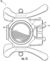
- the first coupling mechanism 110 may comprise a spring-loaded catch 171 (depicted in FIG. 13 ) that extends into the bore 105 and is configured to interact with a circumferential channel extending around a portion of a first end of an external temporary support strut that is received into the bore 105.
- the spring-loaded catch 171 that extends into the bore 105 may be implemented with a geometry such that when a first end of a temporary support strut is received into the bore 105, the spring-loaded catch 171 is urged back into a side wall of the housing 102 without requiring the pull button 112 on an external sidewall 114 of the first end 104 of the housing 102 to be manually actuated.
- the pull button 112 may be manually actuated in order to receive an external support strut into the first coupling mechanism 110.
- the pull button 112 in order to actuate the first coupling mechanism 110, the pull button 112 is manually pulled away from the side wall 114, which retracts the spring-loaded catch 171 within the bore 105 back into the side wall 114 of the housing 104.
- the coupling mechanism 110 may be implemented such that an internal spring urges the catch 171 out of the side wall 114 and into the bore 105 when a manual force is not applied to pull the pull button 112 away from the side wall 114.
- the second end 106 of the housing 102 includes a second coupling mechanism 111.
- the second coupling mechanism 111 may include geometrical features configured to be received into a coupling mechanism similar to that of the first coupling mechanism 110.
- the monitor 100 may be compatible with/removably coupled with similar structures to those that the temporary support strut is configured to be compatible with.
- the geometries of the second coupling mechanism 111 may be similar to the geometries of a first end of a temporary support strut (not depicted) that is configured to be received into the first coupling mechanism 110.
- the second coupling mechanism 111 may have a cylindrical structure 116/cylindrical shaft 116 with a diameter configured to be received into a bore with a bore geometry similar to that of bore 105.
- the second coupling mechanism 11 additionally includes a circumferential channel 118 that extends around a circumference of the cylindrical shaft 116. This circumferential channel 118 may be configured to interact with a catch structure of a coupling mechanism, similar to the catch 171 attached to the pull button 112 of the first coupling mechanism 110. Accordingly, the catch structure is configured to be received into the channel 118, and thereby prevent the cylindrical shaft 116 from translating along the axial direction 108.
- the second coupling mechanism 111 additionally includes a chamfered/filleted surface 120 configured to guide the cylindrical shaft 118 into a receiving bore similar to bore 105.
- the housing 102 may have a cylindrical outer sidewall 114 adjacent to the first end 104 and cylindrical outer sidewall 122 adjacent to the second end 106.
- the housing 102 may include a substantially cuboidal structure 124 spaced between the first end 104 and the second end 106. This substantially cuboidal structure 124 of the housing 102 may include planar outer sidewalls.
- a first sidewall 125 may include a third coupling mechanism 170 (depicted in greater detail in FIG. 9 ).
- the housing 102 additionally includes a monitoring device 130.
- Monitoring device 130 may include external elements visible on the exterior of the monitor 100, and internal elements within the housing 102.
- the monitoring device 130 includes a load cell configured to measure a force exerted on the first coupling mechanism 110. This force may be exerted by an external structure on the coupling mechanism 110. In one example, the external force may be exerted by a removably coupled temporary support strut, a first end of which is securely and removably coupled within the first coupling mechanism 110.
- the load cell of the monitoring device 130 is configured to measure at least a portion of a compressive load (force) exerted on the housing 102 and/or on the first coupling 110.
- force compressive load
- a total force exerted on the monitor 100 may be extrapolated based upon knowledge of the geometry of the load cell relative to the first coupling mechanism 110 as a whole.
- the load cell of the monitoring device 130 may be subjected to a full load/force exerted by an external structure upon the housing 102 of the monitor 100.
- the load cell of the monitoring device 130 may utilize any load cell configuration and/or materials without departing from the scope of the invention as defined by the claims.
- the load cell of the monitoring device 130 may be configured to measure a compressive force and/or a tensile force exerted on the in-line electronic strut monitor 100.
- the load cell of the monitoring device 130 may be configured to measure a torsional force exerted on the in-line electronic strut monitor 100.
- the monitoring device 130 may additionally include an inclination sensor configured to monitor an angle of the in-line electronic strut monitor 100.
- the inclination sensor may be configured to measure an angle of the axial direction 108 relative to level ground or an axis normal to level ground (corresponding to a direction of a force of gravity).
- the inclination sensor may thereby be configured to monitor a tilt angle of a structural member, such as a temporary support strut to which the monitor 100 is removably coupled.
- a temporary support strut may be useful in providing an early indication/warning of a possible collapse of a temporary support structure.
- the monitoring device 130 may include a vibration sensor configured to detect a magnitude and/or frequency/energy content of vibrations to which the housing 102 of the monitor 100 is subjected.
- a vibration sensor configured to detect a magnitude and/or frequency/energy content of vibrations to which the housing 102 of the monitor 100 is subjected.
- This vibration monitoring may be used to detect ongoing seismic activity, such as aftershocks, in an area that has experienced an earthquake.
- the inclination sensor and/or vibration sensor may be implemented using a multi-axis inertial chip positioned within the monitoring device 130.
- This inertial chip may include an accelerometer and/or a gyroscope sensor. It is contemplated that any inertial chip technologies may be utilized, without departing from the scope of the invention as defined by the claims. These technologies may include piezoelectric elements, among others.
- the housing 102 additionally includes a second sidewall 127 that is opposite to a third sidewall 129.
- a fourth sidewall 131 is opposite the first sidewall 125.
- Monitoring device 130 may include a monitoring device housing 132 that is rigidly coupled to the fourth sidewall 131.
- This monitoring device housing 132 may be constructed of any durable material, such as one or more polymers, with said materials configured to withstand incidental contact as the monitor 100 is used within various rescue situations. It is contemplated that the housing 132 may have any geometrical shape.
- the housing 132 includes an electronic interface that may include a graphical interface/screen/ electronic display 134, and/or input knobs/buttons/joysticks 136, otherwise referred to as inputs 136.
- the screen 134 may be a touchscreen or may be interacted with through the inputs 136.
- the inputs 136 may be configured to activate, deactivate, and/or adjust various settings of the monitoring device 130.
- the housing 102 may additionally include a visual beacon 141.
- This visual beacon 141 may include multiple high-intensity lights, which may be light emitting diodes (LEDs).
- This visual beacon 141 may be positioned on both the second side wall 127 and the third sidewall 129. Further, the visual beacon 141 may be actuated based upon a sensor reading from one or more of the sensors of the monitoring device 130.
- the monitoring device 130 may include an audible beacon/siren/alarm that may be configured to output an audible indication that the monitoring device 130 has detected a sensor reading above a predetermined threshold. This predetermined threshold may be associated with a safety threshold of load, angle, or vibration to which the housing 102 is subjected.
- the visual beacon 141 and the audible beacon may be referred to as alert indicators, and may utilize any pattern of lighting and/or sound to alert users within the vicinity of the monitor 100 of a load, a tilt angle, and/or a vibration energy that is above one or more threshold values, or has changed by a threshold amount from set point values set when the monitoring device 130 was installed within a temporary support structure, among others.
- the alert indicators may be configured to indicate that the monitor 100 is running low on battery power, or that the monitor 100 has not been correctly installed within a support structure.
- a total compressive load between the base plates 208 and 210 may be calculated by multiplying by three the compressive load calculated by the monitor 100. It is contemplated that the monitor 100 may be utilized to detect sudden changes in a load, and the total stress between plates 208 and 210 may be of less importance to a user. Additionally, the monitor 100 may be configured to detect an angle of inclination of the strut 202, which may alert a user if the strut 202 appears to be leaning outside of a vertical plane. This specific scenario may represent a potential risk of collapse of a structure that is being supported by the struts 202, 204, and 206. Similarly, the monitor 100 may be configured to monitor vibration within the support configuration 200, which may provide a user with an early indication of a potential failure/collapse event.
- FIG. 3 depicts the in-line electronic strut monitor 100 installed in another example of a temporary structural support configuration 300, according to one or more aspects described herein.
- the monitor 100 is configured to be positioned between a support strut 304 and base plate 302.
- the configuration 300 includes multiple different strut elements beyond that strut 304, which may be configured to provide a shoring of a vertical structure.
- the monitor 100 may be configured to detect a compressive force to which the strut 304 is subjected. A user may extrapolate this detected force information to determine stresses at different points within the configuration 300.
- the in-line electronic strut monitor 100 may be configured to be removably coupled to a variety of structural members intended to form configurations to provide temporary structural support to one or more unstable structures. These formed configurations may utilize multiple different adjustable strut elements, with one of these strut elements being received into the monitor 100. Additionally, the in-line electronic strut monitor 100 may be coupled to an external structure using the third coupling mechanism 170, and/or may not be coupled to a strut.
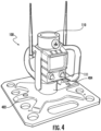
- FIG. 4 depicts the monitor 100 removably coupled to a base plate 402. This baseplate 402 may be configured to position the monitor 100 against a surface that is normal to an axial length of a strut that is received into the first coupling mechanism 110.
- the baseplate 402 may include a coupling mechanism 404 that is similar to the first coupling mechanism 110, and configured to receive the second coupling mechanism 111 of the monitor 100.
- FIG. 5 depicts the monitor 100 removably coupled to a clamp structure 502. Specifically, the clamp structure 502 may be removably coupled to the third coupling mechanism of the monitor 100.
- FIG. 6 depicts the monitor 100 removably coupled to a side plate structure 602. Specifically, the side plate structure 602 may be removably coupled to the third coupling mechanism of the monitor 100.
- FIG. 7 depicts the monitor 100 removably coupled to a suction clamp structure 702. Specifically, the suction clamp structure 702 may be removably coupled to the third coupling mechanism of the monitor 100.
- FIG. 8 depicts another isometric view of the in-line electronic strut monitor 100, according to one or more aspects described herein. Specifically, FIG. 8 depicts a backside view of the monitor 100. FIG. 8 depicts the monitor 100 coupled to the clamp structure 502 of FIG. 5 . The clamp structure 502 is removably coupled to the monitor 100 in an alternative orientation in FIG. 8 .
- FIG. 9 depicts an isometric view of the in-line electronic strut monitor 100, according to one or more aspects described herein. Specifically, FIG. 9 depicts a more detailed view of the third coupling mechanism 170.
- the third coupling mechanism 170 includes an upper rail 902 and a lower rail 904.
- An attachment plate 906 may be removably coupled to the housing 102 of the monitor 100.
- the attachment plate 906 may include an attachment rail 905 with corresponding geometry to the lower rail 904, and configured to catch on the lower rail 904 when the attachment plate 906 is removably coupled to and urged toward an upper attachment bracket 908.
- the upper attachment bracket includes an attachment rail 910 with corresponding geometry to the upper rail 902.
- the upper attachment bracket 908 is removably coupled to the attachment plate 906 by actuating the thumb screw coupling mechanism 912 (which may actuate one or more of a spring-loaded catch or a screw, among others). Removably coupling the upper attachment bracket to the attachment plate 906 clamps the attachment plate 906 and upper attachment bracket 908 between the upper rail 902 and lower rail 904.
- the attachment plate 906 may be coupled to the housing 902 by one or more bolts.
- the attachment plate 906 includes one or more, or an array of threaded holes configured to receive bolts of one or more sizes.
- the attachment plate 906 includes one or more, or an array of threaded holes configured to receive bolts of one or more sizes.
- any size bolts may be utilized, without departing from the scope of the invention as defined by the claims.
- Depicted in FIG. 9 are four bolts 920a-d. These bolts 920a-d are used to couple, for example, the clamp 502 to the housing 102 in FIG. 8 .
- FIG. 10 depicts an isometric view of the in-line electronic strut monitor 100, according to one or more aspects described herein.
- the isometric view of FIG. 10 depicts the monitor 100 without the attachment plate 906 and upper attachment bracket 908.
- the housing 102 includes a battery cover 1002 that is configured to provide access to a user-replaceable battery.
- FIG. 11 depicts a side view of the in-line electronic strut monitor 100, according to one or more aspects described herein.
- FIG. 12 depicts a front view of the in-line electronic strut monitor 100, according to one or more aspects described herein.
- the input controls 136a and 136b may be used to setup the monitor 100 for monitoring one or more of load, vibration and inclination/tilt angle.
- the monitor 100 when installed in a support structure and loaded, the monitor 100 may be initiated by actuating one or more of the input controls 136a-136b. This initiation may record setpoint values of load, tilt angle and vibration frequency/ energy.
- the monitor 100 may actuate one or more alarm elements (e.g., one or more of an audible or visible alarm, and/or an electronic signal communicated to an external device, such as a phone, tablet, computer) when the monitored values of load, tilt angle or vibration frequency/energy change by a certain predetermined amount, such a predetermined percentage amount or predetermined absolute value amount. It is contemplated that this predetermined amount may be any amount. It is also contemplated that the change in monitored value that initiates one or more alarm elements may be an automatically set amount, or may be a manually selected amount, selected using one or more of the input controls 136a-136b.
- FIG. 13 depicts a top view of the in-line electronic strut monitor 100, according to one or more aspects described herein.
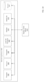
- FIG. 14 schematically depicts a monitoring device 1400, according to one or more aspects described herein.
- the monitoring device 1400 may be similar to monitoring device 130. Accordingly, the monitoring device 1400 may include application-specific integrated circuits and/or general purpose circuitry configured to monitor one or more parameters of a strut to which the monitoring device 1400 is coupled. In one example, the monitoring device 1400 may be configured to monitor load (force), vibration (vibration intensity, frequency among others), and tilt angle.
- the monitoring device 1400 may include a processor 1402 that is configured to control the overall operation of the device 1400.
- the processor 1400 may execute instructions received from memory 1404.
- memory 1404 may be a form of volatile or persistent memory of any type, and may be RAM, ROM, among others.
- the transceiver 1406 may be configured with requisite hardware, firmware and software to facilitate wired and/or wireless communication between the monitoring device 1400 and one or more external devices, such as smartphones, wireless internet routers.
- the transceiver 1406 may be configured to send and/or receive information to/from an application running on a connected device, such a wirelessly connected smartphone or tablet. This application may be used to monitor data generated by the monitoring device 1400 from a remote location, and/or to send setting information to the monitoring device 1400.
- the transceiver 1406 may be configured to receive information from hardware to which the monitoring device 1400 is configured to be removably coupled. Specifically, the transceiver 1406 may receive information from a strut (e.g., strut 304) or another type of support hardware (e.g., base 302). This received information may identify the connected hardware elements, and this information may be used to determine a maximum load to which the coupled hardware may be subjected. It is contemplated that the transceiver 1406 may be configured to communicate across any wired or wireless communication channel utilizing any communication protocol. Examples include, but are not limited to Wi-Fi, Bluetooth, Ethernet, a cellular network, infrared, RFID, among others.
- the transceiver 1406 may be configured with a location determining sensor, such as a global positioning system (GPS) receiver, or another location determining receiver or transceiver.
- a location determining sensor such as a global positioning system (GPS) receiver, or another location determining receiver or transceiver.
- GPS global positioning system
- the monitoring device 1400 includes a load cell transducer 1408 configured to output a signal proportional to a load, or a force, to which the transducer is subjected. Accordingly, the load cell transducer 1408 may be positioned such that the force of a connected strut is transmitted partially or wholly through to the transducer 1408. It is contemplated that any transducer technology may be utilized, without departing from the scope of the invention as defined by the claims.
- the database 1414 may store information related to a type of hardware to which the monitoring device 1400 is coupled, loads exerted on the monitor (e.g., monitor 100) within which the monitoring device 1400 is encapsulated, loading events corresponding to changes in load exerted on the monitor within which the monitoring device 1400 is encapsulated, vibration data, tilt angle data, among others. It is contemplated that any database structure and/or protocol may be used to store the information within database 1414, without departing from the scope of the invention as defined by the claims.
- the various embodiments described herein may be implemented by general-purpose or specialized computer hardware.
- the computer hardware may comprise one or more processors, otherwise referred to as microprocessors, having one or more processing cores configured to allow for parallel processing/execution of instructions.
- the various disclosures described herein may be implemented as software coding, wherein those of skill in the computer arts will recognize various coding languages that may be employed with the disclosures described herein.
- the disclosures described herein may be utilized in the implementation of application-specific integrated circuits (ASICs), or in the implementation of various electronic components comprising conventional electronic circuits (otherwise referred to as off-the-shelf components).
- ASICs application-specific integrated circuits
- One or more of the disclosures described herein may comprise a computer program product having computer-readable medium/media with instructions stored thereon/therein that, when executed by a processor, are configured to perform one or more methods, techniques, systems, or embodiments described herein.
- the instructions stored on the computer-readable media may comprise actions to be executed for performing various steps of the methods, techniques, systems, or embodiments described herein.
- the computer-readable medium/media may comprise a storage medium with instructions configured to be processed by a computing device, and specifically a processor associated with a computing device.
- the received information may include a length of the strut, which may be a fixed length of a length at which the strut has been adjusted.
- a length of the strut which may be a fixed length of a length at which the strut has been adjusted.
- the loading to which a strut may be subjected will depend upon the strut geometry, which may include the material type, material thickness, one or more strut widths, and/or a length of the strut.
- the strut length and type may be identified block 1502 based upon manually entered information received by the monitoring device 1400.
- One or more processes may be executed at block 1504 to identify maximum conditions to which the strut may be subjected, based upon the identified strut type and length from block 1502. These maximum conditions may include a maximum load, a maximum vibration frequency/energy, and/or a maximum tilt angle, among others.
- FIG. 16 depicts an isometric view of an alternative coupling mechanism 1600, according to one or more aspects described herein.
- the coupling mechanism 1600 may be similar to coupling mechanism 170.
- the coupling mechanism 1600 may be configured to be removably coupled to the monitor 100 in a manner similar to the mechanism 170.
- the coupling mechanisms 170 and 1600 may be referred to as "backpack" elements.
- the coupling mechanism 1600 may be utilized to facilitate rapid coupling and uncoupling of structures to the monitor 100. These structures may include clamp structure 502, plate structure 602, and suction clamp structure 702 among others.
- the coupling mechanism 1600 may include attachment rails 1602 and 1604, which may be configured to be removably coupled to the upper rail 902 and lower rail 904 of the monitor 100, as previously described. Similar to coupling mechanism 170, the coupling mechanism 1600 may include an upper attachment bracket 1606 (similar to upper attachment bracket 908) that is removably coupled to an attachment plate 1608 (similar to attachment plate 906) by a thumb screw coupling mechanism 1610 (similar to coupling mechanism 912).
- the plug sleeve 1622 may have 4 substantially symmetrical sides with holes similar to hold 1620 such that the catch 1618 can engage with the plug sleeve 1622 regardless of the orientation of the plug sleeve 1622 relative to the socket sleeve 1612.
- the quick-attach bracket 1614 may additionally include an attachment surface 1624 to which external structures may be bolted. These external structures may include, among others, structures 502, 602, and/or 702. Accordingly, the attachment surface 1624 of the quick-attach bracket 1614 may include tapped or untapped attachment holes configured to receive bolts 1626a-d. It is contemplated, similar to the other structures throughout this disclosure, that the bolts 1626a-d may be of any size and the tapped/ untapped holes into which they are received may be spaced with any spacing pattern relative to one another.
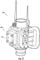
- FIG. 17 depicts an isometric view of an electronic strut monitor 1700, according to one or more aspects described herein.
- the electronic strut monitor 1700 may be similar to electronic strut monitor 100, as previously described.
- the electronic strut monitor 1700 is removably coupled to the backpack coupling mechanism 1600, as described in relation to FIG. 16 .
- the backpack coupling mechanism 1600 is removably coupled to the quick-attach bracket 1614, which may in turn be coupled (bolted) to external clamp elements (not depicted in FIG. 17 ).
- FIG. 18 depicts an isometric view of the electronic strut monitor 1700 decoupled from the backpack coupling mechanism 1600, according to one or more aspects described herein.
- the backpack coupling mechanism 1600 has been decoupled from quick-attach bracket 1614.
- the backpack coupling mechanism 1600 has been decoupled from the electronic strut monitor 1700, which exposes the battery cover 1702.
- This battery cover 1702 provides access to one or more batteries powering the electronics of the monitor 1700.
- the battery cover 1702 may be similar to battery cover 1002, but the battery cover 1702 is affixed to the casing 1704 of the monitor 1700 by two fasteners 1706a, 1706b (which may be two bolts, although the those of ordinary skill in the art will recognize that any fixture type may be used in place of the depicted fixtures throughout this disclosure).
Landscapes
- Physics & Mathematics (AREA)
- General Physics & Mathematics (AREA)
- Engineering & Computer Science (AREA)
- Business, Economics & Management (AREA)
- Aviation & Aerospace Engineering (AREA)
- Health & Medical Sciences (AREA)
- Theoretical Computer Science (AREA)
- Emergency Management (AREA)
- Tourism & Hospitality (AREA)
- Toxicology (AREA)
- General Health & Medical Sciences (AREA)
- Architecture (AREA)
- Electromagnetism (AREA)
- Remote Sensing (AREA)
- Computer Vision & Pattern Recognition (AREA)
- Economics (AREA)
- Artificial Intelligence (AREA)
- Human Resources & Organizations (AREA)
- Marketing (AREA)
- Primary Health Care (AREA)
- Strategic Management (AREA)
- General Business, Economics & Management (AREA)
- Radar, Positioning & Navigation (AREA)
- Computer Networks & Wireless Communication (AREA)
- Microelectronics & Electronic Packaging (AREA)
- Computer Hardware Design (AREA)
- Structural Engineering (AREA)
- Civil Engineering (AREA)
- Mechanical Engineering (AREA)
- Emergency Alarm Devices (AREA)
- Force Measurement Appropriate To Specific Purposes (AREA)
- Testing Of Devices, Machine Parts, Or Other Structures Thereof (AREA)
- Arrangements For Transmission Of Measured Signals (AREA)
Description
- Aspects of this disclosure generally relate to a monitor configured to be removably coupled to a structure or strut that forms part of a temporary support structure.
- A strut may be utilized to brace an unstable structure. For example, one or more struts may be positioned to brace an unstable structure of a vehicle following an accident. In another example, one or more struts may be positioned to reinforce damaged structures within a ship, such as bulkheads, sections of a hull, or hatches. In yet another example, one or more struts may be positioned to bear part, or all, of a weight of a wall, a ceiling, or a roof of an unstable structure. Accordingly, a strut may be utilized by emergency services, or other users, in time-sensitive situations and/or situations in which the types of on-hand materials are limited, and in which there is a possibility of/ there has been structural failure of load-bearing elements.
- The environments in which such struts are used are inherently dangerous. It would be beneficial if the structural condition of the unstable structure could be continuously monitored, optionally from a remote location.
-
CN 108 798 068 AUS 2020/299983 A1 describes a strut which includes a first post section and a second post section. The first post section includes a first portion that is coaxial with, annular to and slidably disposed within a second portion of the second post section. A damping actuator is interposed between the first post section and the second post section, and is arranged to dynamically control a position of the first post section in relation to the second post section.US 2015/144762 A1 describes a system for adjustable construction or demolition temporary supports. The adjustable construction or demolition temporary support includes a plurality of sensor devices for measuring load on the support and signal detection and communication device that being in communication with the sensor devices. The communication device further comprises a display unit and/or audio output unit for providing visual and/or audible alarm for alarming conditions.US 2015/308474 A1 describes a shaft adapter configured to be removably-coupled to shafts of differing diameters. The shaft adapter may have a stepped cylinder cavity with multiple inner diameters. The shaft adapter may further have a spring-loaded adapter ring configured to translate along an inner wall of the stepped cylinder cavity, and may be configured to support an outer wall of a first shaft received into the shaft adapter, or may be configured to be urged into a compressed position when the shaft adapter receives a second shaft. - Accordingly, a need exists for an electronic monitor configured to monitor the structural conditions of a structure or a strut that is part of a bracing system.
- The following presents a simplified summary of the present disclosure in order to provide a basic understanding of some aspects of the invention. This summary is not an extensive overview of the invention. The invention is defined by the claims.
- The present invention is illustrated by way of example and is not limited in the accompanying figures in which like reference numerals indicate similar elements and in which:
-
FIG. 1 depicts an in-line electronic strut monitor that is configured to be removably coupled to a temporary support strut, according to one or more aspects described herein; -
FIGS. 2A-2B depict the in-line electronic strut monitor ofFIG. 1 installed in one example of a temporary structural support configuration, according to one or more aspects described herein; -
FIG. 3 depicts the in-line electronic strut monitor ofFIG. 1 installed in another example of a temporary structural support configuration, according to one or more aspects described herein; -
FIG. 4 depicts the in-line electronic strut monitor ofFIG. 1 removably coupled to a base plate, according to one or more aspects described herein; -
FIG. 5 depicts the in-line electronic strut monitor ofFIG. 1 removably coupled to a clamp structure, according to one or more aspects described herein; -
FIG. 6 depicts the in-line electronic strut monitor ofFIG. 1 removably coupled to a side plate structure, according to one or more aspects described herein; and -
FIG. 7 depicts the in-line electronic strut monitor ofFIG. 1 removably coupled to a suction clamp structure, according to one or more aspects described herein. -
FIG. 8 depicts another isometric view of the in-line electronic strut monitor, according to one or more aspects described herein. -
FIG. 9 depicts an isometric view of the in-line electronic strut monitor, according to one or more aspects described herein. -
FIG. 10 depicts an isometric view of the in-line electronic strut monitor, according to one or more aspects described herein. -
FIG. 11 depicts a side view of the in-line electronic strut monitor, according to one or more aspects described herein. -
FIG. 12 depicts a front view of the in-line electronic strut monitor, according to one or more aspects described herein. -
FIG. 13 depicts a top view of the in-line electronic strut monitor, according to one or more aspects described herein. -
FIG. 14 schematically depicts a monitoring device, according to one or more aspects described herein. -
FIG. 15 is a flowchart diagram that may be executed by the monitoring device ofFIG. 14 , according to one or more aspects described herein. -
FIG. 16 depicts an isometric view of an alternative coupling mechanism, according to one or more aspects described herein. -
FIG. 17 depicts an isometric view of an electronic strut monitor, according to one or more aspects described herein. -
FIG. 18 depicts an isometric view of the electronic strut monitor ofFIG. 17 decoupled from the backpack coupling mechanism, according to one or more aspects described herein. - Further, it is to be understood that the drawings may represent the scale of different elements of one single embodiment; however, the disclosed embodiments are not limited to that particular scale.
- In the following description of the various embodiments, reference is made to the accompanying drawings, which form a part hereof, and in which is shown by way of illustration various embodiments in which aspects of the invention may be practiced. It is to be understood that other embodiments may be utilized, and structural and functional modifications may be made, without departing from the scope of the invention as defined by the claims. It is to be further understood that any of the embodiments described throughout this disclosure may be constructed from one or more material types, including metals, alloys, fiber-reinforced materials, ceramics, polymers, or combinations thereof.
-
FIG. 1 depicts anelectronic monitor device 100. Theelectronic monitor device 100 may be referred to as anelectronic monitor 100, anelectronic strut monitor 100 or an in-lineelectronic strut monitor 100. Theelectronic monitor 100 is configured to be removably coupled to a temporary support strut, according to one or more aspects described herein. Theelectronic monitor 100 may also be configured to be operable when coupled to other structural elements/ structure types. For example, the electronic monitor may be coupled to a clamp that is, in turn, coupled to a structure, such as an unstable structure. - The in-line
electronic strut monitor 100 may otherwise be referred to asmonitor 100 throughout this disclosure, and includes ahousing 102. Thishousing 102 may be configured to be positioned within a structural support system, and as such, may have structural geometries and materials configured to withstand external forces exerted upon thehousing 102 from one or more structural members to which themonitor 100 is removably coupled. In the depicted example ofFIG. 1 thehousing 102 has afirst end 104 spaced apart from asecond end 106 along an axial length that is schematically depicted asaxial length 108/axial direction 108. Thefirst end 104 has afirst bore 105 that extends at least partially into thehousing 104 and is configured to receive a first end of an external temporary support strut (not depicted inFIG. 1 ). In the depicted implementation ofFIG. 1 , thehousing 102 has one or more cylindrical geometries configured to the attached to external cylindrical temporary support strut elements. As such, the schematicaxial length 108 may extend through a center of these cylindrical structures. However, the various disclosures described herein related to an in-lineelectronic strut monitor 100 may utilize a housing with alternative geometries. These alternative geometries are configured to removably couple thehousing 102 to temporary support strut elements with non-cylindrical geometries, such as other prisms, cuboids, among others. It is contemplated that thehousing 102 may be constructed from one or more metals, alloys, polymers, ceramics, or fiber-reinforced materials. In one example, the load-bearing components of thehousing 102 may be constructed from an aluminum alloy. - The
monitor 100 additionally includes afirst coupling mechanism 110 at thefirst end 104. In one example, thefirst coupling mechanism 110 may comprise a spring-loaded catch 171 (depicted inFIG. 13 ) that extends into thebore 105 and is configured to interact with a circumferential channel extending around a portion of a first end of an external temporary support strut that is received into thebore 105. The spring-loadedcatch 171 that extends into thebore 105 may be implemented with a geometry such that when a first end of a temporary support strut is received into thebore 105, the spring-loadedcatch 171 is urged back into a side wall of thehousing 102 without requiring thepull button 112 on anexternal sidewall 114 of thefirst end 104 of thehousing 102 to be manually actuated. In other examples, thepull button 112 may be manually actuated in order to receive an external support strut into thefirst coupling mechanism 110. In one example, in order to actuate thefirst coupling mechanism 110, thepull button 112 is manually pulled away from theside wall 114, which retracts the spring-loadedcatch 171 within thebore 105 back into theside wall 114 of thehousing 104. Thecoupling mechanism 110 may be implemented such that an internal spring urges thecatch 171 out of theside wall 114 and into thebore 105 when a manual force is not applied to pull thepull button 112 away from theside wall 114. - The
second end 106 of thehousing 102 includes asecond coupling mechanism 111. Thesecond coupling mechanism 111 may include geometrical features configured to be received into a coupling mechanism similar to that of thefirst coupling mechanism 110. As such, themonitor 100 may be compatible with/removably coupled with similar structures to those that the temporary support strut is configured to be compatible with. Accordingly, the geometries of thesecond coupling mechanism 111 may be similar to the geometries of a first end of a temporary support strut (not depicted) that is configured to be received into thefirst coupling mechanism 110. Specifically, thesecond coupling mechanism 111 may have acylindrical structure 116/cylindrical shaft 116 with a diameter configured to be received into a bore with a bore geometry similar to that ofbore 105. The second coupling mechanism 11 additionally includes acircumferential channel 118 that extends around a circumference of thecylindrical shaft 116. Thiscircumferential channel 118 may be configured to interact with a catch structure of a coupling mechanism, similar to thecatch 171 attached to thepull button 112 of thefirst coupling mechanism 110. Accordingly, the catch structure is configured to be received into thechannel 118, and thereby prevent thecylindrical shaft 116 from translating along theaxial direction 108. Thesecond coupling mechanism 111 additionally includes a chamfered/filletedsurface 120 configured to guide thecylindrical shaft 118 into a receiving bore similar to bore 105. - The
housing 102 may have a cylindricalouter sidewall 114 adjacent to thefirst end 104 and cylindricalouter sidewall 122 adjacent to thesecond end 106. In addition, thehousing 102 may include a substantiallycuboidal structure 124 spaced between thefirst end 104 and thesecond end 106. This substantiallycuboidal structure 124 of thehousing 102 may include planar outer sidewalls. Afirst sidewall 125 may include a third coupling mechanism 170 (depicted in greater detail inFIG. 9 ). - The geometries of the strut elements that are configured to be received into the
first coupling mechanism 110 and to which thesecond coupling mechanism 111 is configured to attach are described in further detail inU.S. Pat. No. 9,850,930, filed April 15, 2015 - The
housing 102 additionally includes amonitoring device 130.Monitoring device 130 may include external elements visible on the exterior of themonitor 100, and internal elements within thehousing 102. Themonitoring device 130 includes a load cell configured to measure a force exerted on thefirst coupling mechanism 110. This force may be exerted by an external structure on thecoupling mechanism 110. In one example, the external force may be exerted by a removably coupled temporary support strut, a first end of which is securely and removably coupled within thefirst coupling mechanism 110. In one example, the load cell of themonitoring device 130 is configured to measure at least a portion of a compressive load (force) exerted on thehousing 102 and/or on thefirst coupling 110. As such, a total force exerted on themonitor 100 may be extrapolated based upon knowledge of the geometry of the load cell relative to thefirst coupling mechanism 110 as a whole. In another example, the load cell of themonitoring device 130 may be subjected to a full load/force exerted by an external structure upon thehousing 102 of themonitor 100. The load cell of themonitoring device 130 may utilize any load cell configuration and/or materials without departing from the scope of the invention as defined by the claims. Further, the load cell of themonitoring device 130 may be configured to measure a compressive force and/or a tensile force exerted on the in-lineelectronic strut monitor 100. In another example, the load cell of themonitoring device 130 may be configured to measure a torsional force exerted on the in-lineelectronic strut monitor 100. - The
monitoring device 130 may additionally include an inclination sensor configured to monitor an angle of the in-lineelectronic strut monitor 100. As such, the inclination sensor may be configured to measure an angle of theaxial direction 108 relative to level ground or an axis normal to level ground (corresponding to a direction of a force of gravity). The inclination sensor may thereby be configured to monitor a tilt angle of a structural member, such as a temporary support strut to which themonitor 100 is removably coupled. Those of ordinary skill in the art will recognize that monitoring of a tilt angle of a temporary support strut may be useful in providing an early indication/warning of a possible collapse of a temporary support structure. Additionally, themonitoring device 130 may include a vibration sensor configured to detect a magnitude and/or frequency/energy content of vibrations to which thehousing 102 of themonitor 100 is subjected. Those of ordinary skill in the art will recognize that monitoring of vibration may be used to detect an early indication/warning of a possible collapse of a temporary support structure. This vibration monitoring may be used to detect ongoing seismic activity, such as aftershocks, in an area that has experienced an earthquake. The inclination sensor and/or vibration sensor may be implemented using a multi-axis inertial chip positioned within themonitoring device 130. This inertial chip may include an accelerometer and/or a gyroscope sensor. It is contemplated that any inertial chip technologies may be utilized, without departing from the scope of the invention as defined by the claims. These technologies may include piezoelectric elements, among others. - The
housing 102 additionally includes asecond sidewall 127 that is opposite to athird sidewall 129. Afourth sidewall 131 is opposite thefirst sidewall 125.Monitoring device 130 may include amonitoring device housing 132 that is rigidly coupled to thefourth sidewall 131. Thismonitoring device housing 132 may be constructed of any durable material, such as one or more polymers, with said materials configured to withstand incidental contact as themonitor 100 is used within various rescue situations. It is contemplated that thehousing 132 may have any geometrical shape. In one example, thehousing 132 includes an electronic interface that may include a graphical interface/screen/electronic display 134, and/or input knobs/buttons/joysticks 136, otherwise referred to asinputs 136. Thescreen 134 may be a touchscreen or may be interacted with through theinputs 136. In one example, theinputs 136 may be configured to activate, deactivate, and/or adjust various settings of themonitoring device 130. - The
housing 102 may additionally include avisual beacon 141. Thisvisual beacon 141 may include multiple high-intensity lights, which may be light emitting diodes (LEDs). Thisvisual beacon 141 may be positioned on both thesecond side wall 127 and thethird sidewall 129. Further, thevisual beacon 141 may be actuated based upon a sensor reading from one or more of the sensors of themonitoring device 130. In addition, themonitoring device 130 may include an audible beacon/siren/alarm that may be configured to output an audible indication that themonitoring device 130 has detected a sensor reading above a predetermined threshold. This predetermined threshold may be associated with a safety threshold of load, angle, or vibration to which thehousing 102 is subjected. Collectively, thevisual beacon 141 and the audible beacon may be referred to as alert indicators, and may utilize any pattern of lighting and/or sound to alert users within the vicinity of themonitor 100 of a load, a tilt angle, and/or a vibration energy that is above one or more threshold values, or has changed by a threshold amount from set point values set when themonitoring device 130 was installed within a temporary support structure, among others. Additionally, the alert indicators may be configured to indicate that themonitor 100 is running low on battery power, or that themonitor 100 has not been correctly installed within a support structure. - In one example, the
monitoring device 130 may be configured to communicate sensor readings and/or receive setting information from a remote device. Accordingly, themonitoring device 130 may be configured with one or more transceivers configured to facilitate wireless communication between themonitoring device 130 and one or more remote devices, which may include mobile phones, tablets, laptop computers, and the like. It is contemplated that themonitoring device 130 may be configured with the software, firmware, and/or hardware configured to communicate wirelessly using one or more communication protocols, including any Bluetooth®, and/or any Wi-Fi protocol, among others. Themonitoring device 130 may utilizeantennae monitoring device 130 may utilize a single antenna of theantennae monitoring device 130 may be configured with software, firmware, and/or hardware to facilitate wired communication between the monitoring device and one or more remote devices. This wired communication may utilize any wired transmission protocol. It is further contemplated that themonitoring device 130 may include a power supply in the form of one or more batteries configured to provide electrical energy to the multiple components of themonitoring device 130 for a prolonged period of time (e.g. one or more weeks) without requiring themonitoring device 130 to be connected to a wired power source. In one example, themonitoring device 130 may include a port configured to receive a wired power source for recharging of the onboard energy storage batteries of themonitoring device 130. The batteries of themonitoring device 130 may, alternatively, be disposable and user-replaceable, and may use any number and/or type of batteries. - The
monitor 100 additionally includes afirst handle structure 161 rigidly coupled to thesecond side wall 127, and asecond handle structure 162 rigidly coupled to thethird sidewall 129. In one example, thefirst handle structure 161 may be similar to thesecond handle structure 162. Thefirst handle structure 161 includes a closed-loop structure configured to prevent theelectronic display 134 and/or themonitoring device housing 132 from being accidentally impacted by an external surface. In one example, thefirst handle structure 161, when rigidly coupled to thesecond sidewall 127, forms a first sub-handle 166 that extends outward from both thefirst sidewall 125 and thesecond sidewall 127. Thefirst handle structure 161 may additionally form a second sub-handle 168 that extends from both thesecond sidewall 127 and thefourth sidewall 131. Thefirst handle structure 161 and thesecond handle structure 162 may be formed, partially or wholly, from a molded urethane. In another example, thefirst handle structure 161 and thesecond handle structure 162 may be formed, partially or wholly, from a rigid metallic and/or polymeric core that is overmolded with a rubberized material. The external surface of thefirst handle structure 161 and thesecond handle structure 162 may be configured to add additional grip for manual positioning of themonitor 100 and/or prevent sparking if themonitor 100 is accidentally knocked against an external surface. -
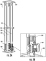
FIG. 2A depicts the in-line electronic strut monitor 100 installed in one example of a temporarystructural support configuration 200, according to one or more aspects described herein.FIG. 2B depicts a closer view of the in-line connection of themonitor 100 between atemporary support strut 202/adjustable strut 202 and abase plate 208. In the depicted configuration ofFIG. 2A , theadjustable strut 202 is one of threesimilar struts monitor 100. In the depictedconfiguration 200, thestruts base plates struts struts plates monitor 100 is placed in-line between thestrut 202 and thebase plate 208, themonitor 100 will be subjected to all of the same compressive force to which thestrut 202 is subjected. In thisexample configuration 200, a total compressive load between thebase plates monitor 100. It is contemplated that themonitor 100 may be utilized to detect sudden changes in a load, and the total stress betweenplates monitor 100 may be configured to detect an angle of inclination of thestrut 202, which may alert a user if thestrut 202 appears to be leaning outside of a vertical plane. This specific scenario may represent a potential risk of collapse of a structure that is being supported by thestruts monitor 100 may be configured to monitor vibration within thesupport configuration 200, which may provide a user with an early indication of a potential failure/collapse event. -
FIG. 3 depicts the in-line electronic strut monitor 100 installed in another example of a temporarystructural support configuration 300, according to one or more aspects described herein. As depicted, themonitor 100 is configured to be positioned between asupport strut 304 andbase plate 302. Theconfiguration 300 includes multiple different strut elements beyond thatstrut 304, which may be configured to provide a shoring of a vertical structure. Themonitor 100 may be configured to detect a compressive force to which thestrut 304 is subjected. A user may extrapolate this detected force information to determine stresses at different points within theconfiguration 300. Additionally or alternatively, a user may monitor a compressive force along thestrut 304 in isolation and/or may utilize themonitor 100 to detect a change in force experienced by thestrut 304. This change in force may be indicative of a shift in a load that is being supported by the temporarystructural support configuration 300, and may be indicative of a potential collapse of the supported structure. Additionally, themonitor 100 may be configured to monitor an angle of inclination of thestrut 304 and/or vibration experienced by thestrut 304/thesupport configuration 300 as a whole. Both the angle and vibration measurements may be utilized to provide a warning of a change in structure being supported by theconfiguration 300. - It is contemplated that the in-line
electronic strut monitor 100 may be configured to be removably coupled to a variety of structural members intended to form configurations to provide temporary structural support to one or more unstable structures. These formed configurations may utilize multiple different adjustable strut elements, with one of these strut elements being received into themonitor 100. Additionally, the in-lineelectronic strut monitor 100 may be coupled to an external structure using thethird coupling mechanism 170, and/or may not be coupled to a strut.FIG. 4 depicts themonitor 100 removably coupled to abase plate 402. Thisbaseplate 402 may be configured to position themonitor 100 against a surface that is normal to an axial length of a strut that is received into thefirst coupling mechanism 110. Thebaseplate 402 may include acoupling mechanism 404 that is similar to thefirst coupling mechanism 110, and configured to receive thesecond coupling mechanism 111 of themonitor 100.FIG. 5 depicts themonitor 100 removably coupled to aclamp structure 502. Specifically, theclamp structure 502 may be removably coupled to the third coupling mechanism of themonitor 100.FIG. 6 depicts themonitor 100 removably coupled to aside plate structure 602. Specifically, theside plate structure 602 may be removably coupled to the third coupling mechanism of themonitor 100.FIG. 7 depicts themonitor 100 removably coupled to asuction clamp structure 702. Specifically, thesuction clamp structure 702 may be removably coupled to the third coupling mechanism of themonitor 100. -
FIG. 8 depicts another isometric view of the in-lineelectronic strut monitor 100, according to one or more aspects described herein. Specifically,FIG. 8 depicts a backside view of themonitor 100.FIG. 8 depicts themonitor 100 coupled to theclamp structure 502 ofFIG. 5 . Theclamp structure 502 is removably coupled to themonitor 100 in an alternative orientation inFIG. 8 . -
FIG. 9 depicts an isometric view of the in-lineelectronic strut monitor 100, according to one or more aspects described herein. Specifically,FIG. 9 depicts a more detailed view of thethird coupling mechanism 170. In one example, thethird coupling mechanism 170 includes anupper rail 902 and alower rail 904. An attachment plate 906 may be removably coupled to thehousing 102 of themonitor 100. In one example, the attachment plate 906 may include anattachment rail 905 with corresponding geometry to thelower rail 904, and configured to catch on thelower rail 904 when the attachment plate 906 is removably coupled to and urged toward anupper attachment bracket 908. The upper attachment bracket includes anattachment rail 910 with corresponding geometry to theupper rail 902. In one example, theupper attachment bracket 908 is removably coupled to the attachment plate 906 by actuating the thumb screw coupling mechanism 912 (which may actuate one or more of a spring-loaded catch or a screw, among others). Removably coupling the upper attachment bracket to the attachment plate 906 clamps the attachment plate 906 andupper attachment bracket 908 between theupper rail 902 andlower rail 904. In another example, the attachment plate 906 may be coupled to thehousing 902 by one or more bolts. - In one example, the attachment plate 906 includes one or more, or an array of threaded holes configured to receive bolts of one or more sizes. Those of ordinary skill in the art will recognize that any size bolts may be utilized, without departing from the scope of the invention as defined by the claims. Depicted in
FIG. 9 are fourbolts 920a-d. Thesebolts 920a-d are used to couple, for example, theclamp 502 to thehousing 102 inFIG. 8 . -
FIG. 10 depicts an isometric view of the in-lineelectronic strut monitor 100, according to one or more aspects described herein. The isometric view ofFIG. 10 depicts themonitor 100 without the attachment plate 906 andupper attachment bracket 908. As depicted, thehousing 102 includes abattery cover 1002 that is configured to provide access to a user-replaceable battery. -
FIG. 11 depicts a side view of the in-lineelectronic strut monitor 100, according to one or more aspects described herein.FIG. 12 depicts a front view of the in-lineelectronic strut monitor 100, according to one or more aspects described herein. The input controls 136a and 136b may be used to setup themonitor 100 for monitoring one or more of load, vibration and inclination/tilt angle. In one example, when installed in a support structure and loaded, themonitor 100 may be initiated by actuating one or more of the input controls 136a-136b. This initiation may record setpoint values of load, tilt angle and vibration frequency/ energy. Themonitor 100 may actuate one or more alarm elements (e.g., one or more of an audible or visible alarm, and/or an electronic signal communicated to an external device, such as a phone, tablet, computer) when the monitored values of load, tilt angle or vibration frequency/energy change by a certain predetermined amount, such a predetermined percentage amount or predetermined absolute value amount. It is contemplated that this predetermined amount may be any amount. It is also contemplated that the change in monitored value that initiates one or more alarm elements may be an automatically set amount, or may be a manually selected amount, selected using one or more of the input controls 136a-136b.FIG. 13 depicts a top view of the in-lineelectronic strut monitor 100, according to one or more aspects described herein. -
FIG. 14 schematically depicts amonitoring device 1400, according to one or more aspects described herein. Themonitoring device 1400 may be similar tomonitoring device 130. Accordingly, themonitoring device 1400 may include application-specific integrated circuits and/or general purpose circuitry configured to monitor one or more parameters of a strut to which themonitoring device 1400 is coupled. In one example, themonitoring device 1400 may be configured to monitor load (force), vibration (vibration intensity, frequency among others), and tilt angle. - The
monitoring device 1400 may include aprocessor 1402 that is configured to control the overall operation of thedevice 1400. Theprocessor 1400 may execute instructions received frommemory 1404. Accordingly,memory 1404 may be a form of volatile or persistent memory of any type, and may be RAM, ROM, among others. Thetransceiver 1406 may be configured with requisite hardware, firmware and software to facilitate wired and/or wireless communication between themonitoring device 1400 and one or more external devices, such as smartphones, wireless internet routers. Thetransceiver 1406 may be configured to send and/or receive information to/from an application running on a connected device, such a wirelessly connected smartphone or tablet. This application may be used to monitor data generated by themonitoring device 1400 from a remote location, and/or to send setting information to themonitoring device 1400. - In one example, the
transceiver 1406 may be configured to receive information from hardware to which themonitoring device 1400 is configured to be removably coupled. Specifically, thetransceiver 1406 may receive information from a strut (e.g., strut 304) or another type of support hardware (e.g., base 302). This received information may identify the connected hardware elements, and this information may be used to determine a maximum load to which the coupled hardware may be subjected. It is contemplated that thetransceiver 1406 may be configured to communicate across any wired or wireless communication channel utilizing any communication protocol. Examples include, but are not limited to Wi-Fi, Bluetooth, Ethernet, a cellular network, infrared, RFID, among others. - Additionally or alternatively, the
transceiver 1406 may be configured with a location determining sensor, such as a global positioning system (GPS) receiver, or another location determining receiver or transceiver. - The
monitoring device 1400 includes aload cell transducer 1408 configured to output a signal proportional to a load, or a force, to which the transducer is subjected. Accordingly, theload cell transducer 1408 may be positioned such that the force of a connected strut is transmitted partially or wholly through to thetransducer 1408. It is contemplated that any transducer technology may be utilized, without departing from the scope of the invention as defined by the claims. - The
monitoring device 1400 additionally includesinterface 1410. Thisinterface 1410 may be configured with user interface hardware, firmware, and/or software configured to facilitate manual interface with themonitoring device 1400 of the strut monitor, such as strut monitor 100. Accordingly, theinterface 1410 may be in operative communication with a display and/orcontrol buttons 1414, which may be similar toelements - The
monitoring device 1400 may additionally include aninertial unit 1412. Thisinertial unit 1412 may include an accelerometer, and/or a gyroscope. Further, the accelerometer and/or the gyroscope may be sensitive along one, two, or three mutually perpendicular axes. Themonitoring device 1400 may additionally include adatabase 1414 that may be configured to store data at recorded by themonitoring device 1400 for subsequent review and/or analysis. Thedatabase 1414 may store information related to a type of hardware to which themonitoring device 1400 is coupled, loads exerted on the monitor (e.g., monitor 100) within which themonitoring device 1400 is encapsulated, loading events corresponding to changes in load exerted on the monitor within which themonitoring device 1400 is encapsulated, vibration data, tilt angle data, among others. It is contemplated that any database structure and/or protocol may be used to store the information withindatabase 1414, without departing from the scope of the invention as defined by the claims. - In one example, the
monitoring device 1400 may include recorder functionality, which may be referred to as black box functionality. This black box functionality may allow a user to analyze data following the use of themonitoring device 1400 in a rescue scenario during which it is used to monitor a load, vibration, and/or tilt angle of a strut used to shore an otherwise unstable external structure. The black box functionality may automatically communicate data stored indatabase 1414 to an external device to which themonitoring device 1400 is wired or wirelessly connected upon detection of a trigger event, such as a change in load, tilt angle, and/or vibration intensity above a threshold amount. In another example, themonitoring device 1400 may continuously store data locally withindatabase 1414 and simultaneously store that same data, or a portion thereof, in a remote location away from themonitoring device 1400. In one example, themonitoring device 1400 may store load, vibration, and/or tilt angle information for a strut to which themonitoring device 1400 is connected, as well as from separate monitoring devices to which thedevice 1400 may be in wired or wireless communication. In this scenario, Themonitoring device 1400 may act as a redundant database storing information from separate monitoring devices used to support various structures at the site of a rescue or other type of shoring operation. In another example, the black box functionality of themonitoring device 1400 may transmit stored information fromdatabase 1414 to a user upon receipt of a request by that user. The information may be transmitted to thedisplay 1414, and/or to thetransceiver 1406 for communication to an external device. - The disclosure is operational with numerous other general purpose or special purpose computing system environments or configurations. Examples of well-known computing systems, environments, and/or configurations that may be suitable for use with the disclosure include, but are not limited to, personal computers, server computers, hand-held or laptop devices, multiprocessor systems, microprocessor-based systems, set top boxes, programmable consumer electronics, network PCs, minicomputers, mainframe computers, and distributed computing environments that include any of the above systems or devices, and the like.
- The disclosure may be described in the general context of computer-executable instructions, such as program modules, being executed by a computer. Generally, program modules include routines, programs, objects, components, data structures, and the like that perform particular tasks or implement particular abstract data types. The disclosure may also be practiced in distributed computing environments where tasks are performed by remote processing devices that are linked, for example, through a communications network. In a distributed computing environment, program modules may be located in both local and remote computer storage media including memory storage devices.
- The various embodiments described herein may be implemented by general-purpose or specialized computer hardware. In one example, the computer hardware may comprise one or more processors, otherwise referred to as microprocessors, having one or more processing cores configured to allow for parallel processing/execution of instructions. As such, the various disclosures described herein may be implemented as software coding, wherein those of skill in the computer arts will recognize various coding languages that may be employed with the disclosures described herein. Additionally, the disclosures described herein may be utilized in the implementation of application-specific integrated circuits (ASICs), or in the implementation of various electronic components comprising conventional electronic circuits (otherwise referred to as off-the-shelf components). Furthermore, those of ordinary skill in the art will understand that the various descriptions included in this disclosure may be implemented as data signals communicated using a variety of different technologies and processes. For example, the descriptions of the various disclosures described herein may be understood as comprising one or more streams of data signals, data instructions, or requests, and physically communicated as bits or symbols represented by differing voltage levels, currents, electromagnetic waves, magnetic fields, optical fields, or combinations thereof.
- One or more of the disclosures described herein may comprise a computer program product having computer-readable medium/media with instructions stored thereon/therein that, when executed by a processor, are configured to perform one or more methods, techniques, systems, or embodiments described herein. As such, the instructions stored on the computer-readable media may comprise actions to be executed for performing various steps of the methods, techniques, systems, or embodiments described herein. Furthermore, the computer-readable medium/media may comprise a storage medium with instructions configured to be processed by a computing device, and specifically a processor associated with a computing device. As such the computer-readable medium may include a form of persistent or volatile memory such as a hard disk drive (HDD), a solid state drive (SSD), an optical disk (CD-ROMs, DVDs), tape drives, floppy disk, ROM, RAM, EPROM, EEPROM, DRAM, VRAM, flash memory, RAID devices, remote data storage (cloud storage, and the like), or any other media type or storage device suitable for storing data thereon/therein. Additionally, combinations of different storage media types may be implemented into a hybrid storage device. In one implementation, a first storage medium may be prioritized over a second storage medium, such that different workloads may be implemented by storage media of different priorities.
- Further, the computer-readable media may store software code/instructions configured to control one or more of a general-purpose, or a specialized computer. Said software may be utilized to facilitate interface between a human user and a computing device, and wherein said software may include device drivers, operating systems, and applications. As such, the computer-readable media may store software code/instructions configured to perform one or more implementations described herein.
- Those of ordinary skill in the art will understand that the various illustrative logical blocks, modules, circuits, techniques, or method steps of those implementations described herein may be implemented as electronic hardware devices, computer software, or combinations thereof. As such, various illustrative modules/components have been described throughout this disclosure in terms of general functionality, wherein one of ordinary skill in the art will understand that the described disclosures may be implemented as hardware, software, or combinations of both.
- The one or more implementations described throughout this disclosure may utilize logical blocks, modules, and circuits that may be implemented or performed with a general-purpose processor, a digital signal processor (DSP), an application-specific integrated circuit (ASIC), a field programmable gate array (FPGA) or other programmable logic device, discrete gate or transistor logic, discrete hardware components, or any combination thereof designed to perform the functions described herein. A general-purpose processor may be a microprocessor, or any conventional processor, controller, microcontroller, or state machine. A processor may also be implemented as a combination of computing devices, e.g., a combination of a DSP and a microprocessor, a plurality of microprocessors, one or more microprocessors in conjunction with a DSP core, or any other such configuration.
- The techniques or steps of a method described in connection with the embodiments disclosed herein may be embodied directly in hardware, in software executed by a processor, or in a combination of the two. In some embodiments, any software module, software layer, or thread described herein may comprise an engine comprising firmware or software and hardware configured to perform embodiments described herein. Functions of a software module or software layer described herein may be embodied directly in hardware, or embodied as software executed by a processor, or embodied as a combination of the two. A software module may reside in RAM memory, flash memory, ROM memory, EPROM memory, EEPROM memory, registers, hard disk, a removable disk, a CD-ROM, or any other form of storage medium known in the art. An exemplary storage medium is coupled to the processor such that the processor can read data from, and write data to, the storage medium. In the alternative, the storage medium may be integral to the processor. The processor and the storage medium may reside in an ASIC. The ASIC may reside in a user device. In the alternative, the processor and the storage medium may reside as discrete components in a user device.
-
FIG. 15 is a flowchart diagram 1500 that may be executed by themonitoring device 1400, according to one or more aspects described herein. In one example, one or more processes may be executed atblock 1502 offlowchart 1500 to identify a length and/or a type of a strut (e.g., strut 300) (or other support hardware, such as base plate 302) that is removably coupled to themonitoring device 1400. In one example, this identification may be automatic, based upon a signal received from the attached hardware. Further this signal may be received from a Bluetooth low energy (BTLE) transceiver within the attached hardware, or from an RFID tag, among others. Further, the received information may include a length of the strut, which may be a fixed length of a length at which the strut has been adjusted. Those of ordinary skill in the art will recognize that the loading to which a strut may be subjected will depend upon the strut geometry, which may include the material type, material thickness, one or more strut widths, and/or a length of the strut. In additional or alternative examples, the strut length and type may be identifiedblock 1502 based upon manually entered information received by themonitoring device 1400. - One or more processes may be executed at
block 1504 to identify maximum conditions to which the strut may be subjected, based upon the identified strut type and length fromblock 1502. These maximum conditions may include a maximum load, a maximum vibration frequency/energy, and/or a maximum tilt angle, among others. - One or more processes may be executed at block 1506 to set a threshold above which the monitor will execute an alert. This threshold may be a load threshold, a vibration threshold, or a tilt angle threshold, among others. The threshold set at block 1506 may be automatically determined based upon a lookup table stored within the
database 1414, and/or may be manually entered into themonitoring device 1400. -
Decision block 1508 may correspond to one or more monitoring processes during which themonitoring device 1400 periodically calculates one or more of a load, vibration intensity and/or frequency, and/or tilt angle, and compares the calculated data to the threshold set at block 1506. If the threshold has not been reached,flowchart 1500 proceeds to block 1510 and thestrut monitor 1400 continues monitoring the structural support system that includes one or more struts. If one or more thresholds are reached,flowchart 1500 proceeds to block 1512, at which one or more alarms may be activated. These one or more alarms may be local to the device 1400 (e.g., on the monitor 100), and/or may be remote. A local alarm may include an audible and/or visible alert signal. In one example, a remote alarm may include a signal to activate a warning on a device to which thestrut monitor 1400 is connected. -
FIG. 16 depicts an isometric view of analternative coupling mechanism 1600, according to one or more aspects described herein. Thecoupling mechanism 1600 may be similar tocoupling mechanism 170. As such, thecoupling mechanism 1600 may be configured to be removably coupled to themonitor 100 in a manner similar to themechanism 170. In one exam, thecoupling mechanisms - Advantageously, the
coupling mechanism 1600 may be utilized to facilitate rapid coupling and uncoupling of structures to themonitor 100. These structures may includeclamp structure 502,plate structure 602, andsuction clamp structure 702 among others. Thecoupling mechanism 1600 may includeattachment rails upper rail 902 andlower rail 904 of themonitor 100, as previously described. Similar tocoupling mechanism 170, thecoupling mechanism 1600 may include an upper attachment bracket 1606 (similar to upper attachment bracket 908) that is removably coupled to an attachment plate 1608 (similar to attachment plate 906) by a thumb screw coupling mechanism 1610 (similar to coupling mechanism 912). Thecoupling mechanism 1600 additionally includes asocket sleeve 1612 into which a quick-attachbracket 1614 is removably coupled by a pull button (otherwise referred to as a pull pin) 1616. Thepull button 1616 which includes a spring-actuatedcatch 1618 that is received into a corresponding hole or depression of the quick-attachbracket 1614. One of these holes of the quick-attachbracket 1614 is depicted inFIG. 16 aselement 1620. In one example, the quick-attachbracket 1614 has a rounded squareplug sleeve geometry 1622 configured to be received into the rounded square geometry of thesocket sleeve 1612. Further, theplug sleeve 1622 may have 4 substantially symmetrical sides with holes similar to hold 1620 such that thecatch 1618 can engage with theplug sleeve 1622 regardless of the orientation of theplug sleeve 1622 relative to thesocket sleeve 1612. The quick-attachbracket 1614 may additionally include anattachment surface 1624 to which external structures may be bolted. These external structures may include, among others,structures attachment surface 1624 of the quick-attachbracket 1614 may include tapped or untapped attachment holes configured to receivebolts 1626a-d. It is contemplated, similar to the other structures throughout this disclosure, that thebolts 1626a-d may be of any size and the tapped/ untapped holes into which they are received may be spaced with any spacing pattern relative to one another. -
FIG. 17 depicts an isometric view of anelectronic strut monitor 1700, according to one or more aspects described herein. Theelectronic strut monitor 1700 may be similar toelectronic strut monitor 100, as previously described. As depicted, theelectronic strut monitor 1700 is removably coupled to thebackpack coupling mechanism 1600, as described in relation toFIG. 16 . Further, thebackpack coupling mechanism 1600 is removably coupled to the quick-attachbracket 1614, which may in turn be coupled (bolted) to external clamp elements (not depicted inFIG. 17 ). -
FIG. 18 depicts an isometric view of theelectronic strut monitor 1700 decoupled from thebackpack coupling mechanism 1600, according to one or more aspects described herein. As depicted inFIG. 18 , thebackpack coupling mechanism 1600 has been decoupled from quick-attachbracket 1614. When thebackpack coupling mechanism 1600 has been decoupled from theelectronic strut monitor 1700, which exposes thebattery cover 1702. Thisbattery cover 1702 provides access to one or more batteries powering the electronics of themonitor 1700. Thebattery cover 1702 may be similar tobattery cover 1002, but thebattery cover 1702 is affixed to thecasing 1704 of themonitor 1700 by twofasteners - Aspects of the embodiments have been described in terms of illustrative embodiments thereof. Numerous other embodiments, modifications and variations within the scope of the appended claims will occur to persons of ordinary skill in the art from a review of this disclosure. For example, one of ordinary skill in the art will appreciate that the steps illustrated in the illustrative figures may be performed in other than the recited order, and that one or more steps illustrated may be optional in accordance with aspects of the embodiments.
- Accordingly, it will be understood that the invention is not to be limited to the embodiments disclosed herein, but is to be understood from the following claims.
Claims (9)
- An electronic monitor (100), comprising:a housing (102) having a first end (104) with a bore (105) extending into the housing (102) and a second end spaced apart from the first end (104) along an axial length, wherein the housing (102) comprises a first sidewall (125), and the housing (102) further comprises a second sidewall and a third sidewall, the electronic monitor (100) further comprising a first handle structure (161) rigidly coupled to the second sidewall, and a second handle structure (162) rigidly coupled to the third sidewall;a first coupling mechanism (110) at the first end (104) configured to removably couple the first end (104) of the housing (102) to a temporary support strut;a second coupling mechanism at the second end of the housing (102), the second coupling mechanism comprising a cylindrical shaft (116) with a circumferential channel (118);a monitoring device positioned within the housing (102), the monitoring device comprising a load cell configured to measure at least a portion of a force exerted upon the first coupling mechanism (110) by the temporary support strut; andan electronic interface (134), configured to communicate to a user information about the force measured by the load cell, characterized in that the first and second handle structures each comprise a closed-loop structure additionally configured to prevent the electronic interface (134) from being accidentally impacted by an external surface.
- The electronic monitor (100) of claim 1, wherein the electronic interface (1410) comprises a wireless transceiver configured to transmit sensor information to a remote device of the user.
- The electronic monitor (100) of claim 1, wherein the monitoring device further comprises an inclination sensor configured to detect a tilt angle of the axial length of the housing (102).
- The electronic monitor (100) of claim 1, wherein the monitoring device comprises a vibration sensor.
- The electronic monitor (100) of any one of claims 1 to 3, comprising:a third coupling mechanism positioned on a sidewall that extends along a portion of the housing (102) between the first end (104) and the second end,wherein the monitoring device comprises a vibration sensor.
- The electronic monitor (100) of claim 5, wherein the second coupling mechanism or the third coupling mechanism is configured to be removably coupled to an external attachment structure.
- The electronic monitor (100) of claim 5, wherein the electronic interface (134) comprises an electronic display attached to a fourth sidewall (131) of the housing (102).
- The electronic monitor (100) of claim 5, wherein the monitoring device comprises an alarm configured with audible and visible alert indicators.
- The electronic monitor (100) of claim 5, wherein the first coupling mechanism (110) comprises a spring-loaded catch configured to extend from the sidewall of the housing (102) into the bore (105), and configured to be received into a channel of the first end (104) of the temporary support strut.
Applications Claiming Priority (4)
| Application Number | Priority Date | Filing Date | Title |
|---|---|---|---|
| US202163142331P | 2021-01-27 | 2021-01-27 | |
| US202163181762P | 2021-04-29 | 2021-04-29 | |
| US17/582,864 US11763109B2 (en) | 2021-01-27 | 2022-01-24 | Electronic strut monitor |
| PCT/US2022/070331 WO2022165480A1 (en) | 2021-01-27 | 2022-01-25 | Electronic strut monitor |
Publications (3)
| Publication Number | Publication Date |
|---|---|
| EP4285090A1 EP4285090A1 (en) | 2023-12-06 |
| EP4285090C0 EP4285090C0 (en) | 2025-06-04 |
| EP4285090B1 true EP4285090B1 (en) | 2025-06-04 |
Family
ID=82495584
Family Applications (1)
| Application Number | Title | Priority Date | Filing Date |
|---|---|---|---|
| EP22704268.6A Active EP4285090B1 (en) | 2021-01-27 | 2022-01-25 | Electronic strut monitor |
Country Status (5)
| Country | Link |
|---|---|
| US (1) | US11763109B2 (en) |
| EP (1) | EP4285090B1 (en) |
| JP (1) | JP7520241B2 (en) |
| KR (1) | KR102665769B1 (en) |
| CN (1) | CN116964423B (en) |
Families Citing this family (1)
| Publication number | Priority date | Publication date | Assignee | Title |
|---|---|---|---|---|
| CN112789486B (en) * | 2019-07-05 | 2024-03-08 | 林振宇 | Force and tilt monitoring system with self-positioning recognition |
Citations (1)
| Publication number | Priority date | Publication date | Assignee | Title |
|---|---|---|---|---|
| US20070255424A1 (en) * | 2006-04-28 | 2007-11-01 | Leydet Michael G | Prosthetic sensing systems and methods |
Family Cites Families (44)
| Publication number | Priority date | Publication date | Assignee | Title |
|---|---|---|---|---|
| US1737514A (en) * | 1929-04-01 | 1929-11-26 | Nikolish Mike | Signal for mines |
| US3594773A (en) * | 1968-11-12 | 1971-07-20 | Ellsworth V Conkle | Mine roof gauge and indicator |
| US3662596A (en) * | 1970-11-12 | 1972-05-16 | Goodyear Tire & Rubber | Device for measuring stress in metal tire cords |
| US5668325A (en) * | 1996-03-27 | 1997-09-16 | Cyprus Amax Coal Company | Method and apparatus for determining compressive stress in pillars |
| US5979218A (en) * | 1997-11-12 | 1999-11-09 | Chrysler Corporation | Strut mount transducer |
| US6957166B1 (en) * | 1998-04-30 | 2005-10-18 | The United States Of America As Represented By The Department Of Health And Human Services | Method and apparatus for load rate monitoring |
| JP4040971B2 (en) | 2002-12-27 | 2008-01-30 | 株式会社山武 | Differential pressure / pressure transmitter |
| US6823753B1 (en) * | 2003-05-16 | 2004-11-30 | Asm America, Inc. | Sensor signal transmission from processing system |
| US20050103123A1 (en) * | 2003-11-14 | 2005-05-19 | Newman Kenneth R. | Tubular monitor systems and methods |
| US7496454B2 (en) * | 2004-07-19 | 2009-02-24 | University Of Virginia Patent Foundation | High mast inspection system, equipment and method |
| FR2963681B1 (en) * | 2010-08-04 | 2012-08-31 | Sercel Rech Const Elect | DATA ACQUISITION MODULE AND CABLE CONNECTOR FOR FIXING THE MODULE |
| US8474331B2 (en) * | 2006-02-24 | 2013-07-02 | David Pekin | Force measurement system |
| US7584932B2 (en) * | 2007-10-23 | 2009-09-08 | Lung Ching Shih | Construction prop |
| ZA200900118B (en) * | 2008-01-07 | 2009-12-30 | David Douglas Senogles | Monitoring system |
| WO2014043592A2 (en) * | 2012-09-14 | 2014-03-20 | Flir Systems, Inc. | Measurement device for electrical installations and related methods |
| JP2011085514A (en) * | 2009-10-16 | 2011-04-28 | Hitachi Cable Ltd | Load measuring sensor for rod-shaped body, and load measuring system |
| CN102844523B (en) * | 2010-02-19 | 2014-09-24 | 科学与工业研究会 | A device for roof support of underground mine/tunnel |
| GB2479008B (en) * | 2010-04-20 | 2012-06-06 | Byrne Bros Formwork Ltd | Power tool for falsework assemblies |
| WO2012048237A2 (en) * | 2010-10-08 | 2012-04-12 | Checkit Technologies, Llc | Structural integrity system and methods |
| US20130126249A1 (en) * | 2011-11-22 | 2013-05-23 | Simmonds Precision Products, Inc. | Load cell and applications thereof |
| US8973899B2 (en) * | 2011-12-12 | 2015-03-10 | Mark Allen BUCKINGHAM | Jacking pole |
| US9033619B2 (en) * | 2012-12-14 | 2015-05-19 | John Riggle, JR. | Trench shoring apparatuses |
| WO2015035430A2 (en) * | 2013-09-05 | 2015-03-12 | Ncm Innovations (Pty) Ltd | Rock wall closure detection device |
| US10225629B2 (en) * | 2013-11-25 | 2019-03-05 | Chi Hung Louis Lam | System for monitoring condition of adjustable construction temporary supports |
| US9850930B2 (en) * | 2014-04-24 | 2017-12-26 | Paratech, Incorporated | Shaft adapter |
| GB2526883B (en) * | 2014-06-06 | 2021-04-21 | Mmc Innovations Llp | Temporary support & raising device |
| US9534406B2 (en) * | 2014-10-01 | 2017-01-03 | Paratech, Incorporated | Adjustable strut with locking mechanism |
| US9955274B2 (en) * | 2015-04-08 | 2018-04-24 | The Boeing Company | Vibration monitoring systems |
| GB201506496D0 (en) * | 2015-04-16 | 2015-06-03 | Expro North Sea Ltd | Measurement system and methods |
| WO2016209909A1 (en) * | 2015-06-22 | 2016-12-29 | Mc10 Inc. | Method and system for structural health monitoring |
| US11306492B2 (en) * | 2016-06-24 | 2022-04-19 | Apache Industrial Services, Inc | Load bearing components and safety deck of an integrated construction system |
| US10436759B2 (en) * | 2017-01-12 | 2019-10-08 | Fisher Controls International Llc | Methods and apparatus to monitor a condition of a structure |
| US10302510B2 (en) * | 2017-01-30 | 2019-05-28 | Tecat Performance Systems, Llc | Wireless axial load cell and sensor assembly |
| JP6910840B2 (en) | 2017-04-24 | 2021-07-28 | 株式会社マキタ | Electric tool |
| US10801593B2 (en) * | 2017-04-26 | 2020-10-13 | Paratech, Incorporated | Strut extender mechanism |
| US10473540B2 (en) * | 2017-09-01 | 2019-11-12 | GM Global Technology Operations LLC | Gas strut force active monitor system |
| CN207589672U (en) | 2017-10-27 | 2018-07-10 | 贵溪市原林果业专业合作社 | A kind of planting fruit trees monitoring alarm |
| CN108798068A (en) | 2018-07-05 | 2018-11-13 | 象山企盛智能科技有限公司 | A kind of safety supports system suitable for assembled architecture and bridge construction |
| US11124978B2 (en) | 2019-03-20 | 2021-09-21 | Big Time Investment, Llc | Strut for a multi-story building |
| CN112789486B (en) * | 2019-07-05 | 2024-03-08 | 林振宇 | Force and tilt monitoring system with self-positioning recognition |
| US20220364944A1 (en) * | 2019-10-06 | 2022-11-17 | Christopher Robert Fuller | External-Mounted Strain Sensor System for Non-Invasive Measurement of Internal Static and Dynamic Pressures in Elastic Bodies |
| DE102019216792A1 (en) * | 2019-10-30 | 2021-05-06 | Peri Gmbh | Computer-aided method and system for determining and visualizing force flows in scaffolding |
| CN110847632A (en) | 2019-12-19 | 2020-02-28 | 天津联东兴达科技有限公司 | Building supporting device |
| US11686710B2 (en) * | 2020-03-31 | 2023-06-27 | Evident Canada, Inc. | Longitudinal and circumferential ultrasound scanner |
-
2022
- 2022-01-24 US US17/582,864 patent/US11763109B2/en active Active
- 2022-01-25 KR KR1020237028976A patent/KR102665769B1/en active Active
- 2022-01-25 CN CN202280020242.XA patent/CN116964423B/en active Active
- 2022-01-25 EP EP22704268.6A patent/EP4285090B1/en active Active
- 2022-01-25 JP JP2023546029A patent/JP7520241B2/en active Active
Patent Citations (1)
| Publication number | Priority date | Publication date | Assignee | Title |
|---|---|---|---|---|
| US20070255424A1 (en) * | 2006-04-28 | 2007-11-01 | Leydet Michael G | Prosthetic sensing systems and methods |
Also Published As
| Publication number | Publication date |
|---|---|
| EP4285090A1 (en) | 2023-12-06 |
| CN116964423B (en) | 2024-05-28 |
| EP4285090C0 (en) | 2025-06-04 |
| JP2024506845A (en) | 2024-02-15 |
| US11763109B2 (en) | 2023-09-19 |
| KR102665769B1 (en) | 2024-05-14 |
| KR20230133906A (en) | 2023-09-19 |
| JP7520241B2 (en) | 2024-07-22 |
| CN116964423A (en) | 2023-10-27 |
| US20220237395A1 (en) | 2022-07-28 |
Similar Documents
| Publication | Publication Date | Title |
|---|---|---|
| US11255989B2 (en) | Building integrity assessment system | |
| US11745035B2 (en) | Fall protection compliance system and method | |
| KR101064577B1 (en) | Distress Rescue System Following Collapse | |
| EP4285090B1 (en) | Electronic strut monitor | |
| US10888723B2 (en) | Self-retracting lanyard with fall protection harness tracker | |
| CN106840091A (en) | A kind of falsework settlement monitoring prior-warning device | |
| US12467792B2 (en) | Flame detecting arrangement | |
| CN107962595B (en) | Robot, which falls down to the ground, protects system and method | |
| CN112789486A (en) | Force and inclination monitoring system with self-positioning identification | |
| CN110192001A (en) | Sensor for rotatable element | |
| JP2022097703A (en) | Electric tool | |
| CN110006525A (en) | A kind of defeated aerial pipeline distribution stress system of condition monitoring of length and method | |
| US20250121469A1 (en) | Power tool including fall detection and autostop | |
| KR101904092B1 (en) | Management method and system for air fender | |
| WO2022165480A1 (en) | Electronic strut monitor | |
| US20230264654A1 (en) | Catalytic converter alarm | |
| CN211180199U (en) | Displacement detector | |
| KR101502062B1 (en) | Earthquake Sensing Method and Seismometer using the same | |
| JP3252471U (en) | Safety belt usage status confirmation device and its communication master unit storage device | |
| JP3997122B2 (en) | Sinking / floating detection system, sinking / floating detection method, sinking / floating detection program, and computer-readable recording medium | |
| WO2026018194A1 (en) | Smart harness | |
| KR20240001737U (en) | Chain and wire monitoring system | |
| JP5850158B2 (en) | Portable device, information transmission method and information transmission program | |
| HK40042819B (en) | Force and inclination monitoring system with self-position recognition | |
| WO2014107866A1 (en) | Hook deviation angle detection and monitoring apparatus and crane |
Legal Events
| Date | Code | Title | Description |
|---|---|---|---|
| STAA | Information on the status of an ep patent application or granted ep patent |
Free format text: STATUS: UNKNOWN |
|
| STAA | Information on the status of an ep patent application or granted ep patent |
Free format text: STATUS: THE INTERNATIONAL PUBLICATION HAS BEEN MADE |
|
| PUAI | Public reference made under article 153(3) epc to a published international application that has entered the european phase |
Free format text: ORIGINAL CODE: 0009012 |
|
| STAA | Information on the status of an ep patent application or granted ep patent |
Free format text: STATUS: REQUEST FOR EXAMINATION WAS MADE |
|
| 17P | Request for examination filed |
Effective date: 20230731 |
|
| AK | Designated contracting states |
Kind code of ref document: A1 Designated state(s): AL AT BE BG CH CY CZ DE DK EE ES FI FR GB GR HR HU IE IS IT LI LT LU LV MC MK MT NL NO PL PT RO RS SE SI SK SM TR |
|
| DAV | Request for validation of the european patent (deleted) | ||
| DAX | Request for extension of the european patent (deleted) | ||
| STAA | Information on the status of an ep patent application or granted ep patent |
Free format text: STATUS: EXAMINATION IS IN PROGRESS |
|
| 17Q | First examination report despatched |
Effective date: 20240605 |
|
| GRAP | Despatch of communication of intention to grant a patent |
Free format text: ORIGINAL CODE: EPIDOSNIGR1 |
|
| STAA | Information on the status of an ep patent application or granted ep patent |
Free format text: STATUS: GRANT OF PATENT IS INTENDED |
|
| INTG | Intention to grant announced |
Effective date: 20241121 |
|
| RAP3 | Party data changed (applicant data changed or rights of an application transferred) |
Owner name: PARATECH, INCORPORATED |
|
| GRAS | Grant fee paid |
Free format text: ORIGINAL CODE: EPIDOSNIGR3 |
|
| GRAA | (expected) grant |
Free format text: ORIGINAL CODE: 0009210 |
|
| STAA | Information on the status of an ep patent application or granted ep patent |
Free format text: STATUS: THE PATENT HAS BEEN GRANTED |
|
| AK | Designated contracting states |
Kind code of ref document: B1 Designated state(s): AL AT BE BG CH CY CZ DE DK EE ES FI FR GB GR HR HU IE IS IT LI LT LU LV MC MK MT NL NO PL PT RO RS SE SI SK SM TR |
|
| REG | Reference to a national code |
Ref country code: GB Ref legal event code: FG4D |
|
| REG | Reference to a national code |
Ref country code: CH Ref legal event code: EP |
|
| REG | Reference to a national code |
Ref country code: DE Ref legal event code: R096 Ref document number: 602022015470 Country of ref document: DE |
|
| REG | Reference to a national code |
Ref country code: IE Ref legal event code: FG4D |
|
| U01 | Request for unitary effect filed |
Effective date: 20250627 |
|
| U07 | Unitary effect registered |
Designated state(s): AT BE BG DE DK EE FI FR IT LT LU LV MT NL PT RO SE SI Effective date: 20250704 |
|
| PG25 | Lapsed in a contracting state [announced via postgrant information from national office to epo] |
Ref country code: ES Free format text: LAPSE BECAUSE OF FAILURE TO SUBMIT A TRANSLATION OF THE DESCRIPTION OR TO PAY THE FEE WITHIN THE PRESCRIBED TIME-LIMIT Effective date: 20250604 |
|
| PG25 | Lapsed in a contracting state [announced via postgrant information from national office to epo] |
Ref country code: NO Free format text: LAPSE BECAUSE OF FAILURE TO SUBMIT A TRANSLATION OF THE DESCRIPTION OR TO PAY THE FEE WITHIN THE PRESCRIBED TIME-LIMIT Effective date: 20250904 Ref country code: GR Free format text: LAPSE BECAUSE OF FAILURE TO SUBMIT A TRANSLATION OF THE DESCRIPTION OR TO PAY THE FEE WITHIN THE PRESCRIBED TIME-LIMIT Effective date: 20250905 |
|
| PG25 | Lapsed in a contracting state [announced via postgrant information from national office to epo] |
Ref country code: PL Free format text: LAPSE BECAUSE OF FAILURE TO SUBMIT A TRANSLATION OF THE DESCRIPTION OR TO PAY THE FEE WITHIN THE PRESCRIBED TIME-LIMIT Effective date: 20250604 |
|
| PG25 | Lapsed in a contracting state [announced via postgrant information from national office to epo] |
Ref country code: HR Free format text: LAPSE BECAUSE OF FAILURE TO SUBMIT A TRANSLATION OF THE DESCRIPTION OR TO PAY THE FEE WITHIN THE PRESCRIBED TIME-LIMIT Effective date: 20250604 |
|
| PG25 | Lapsed in a contracting state [announced via postgrant information from national office to epo] |
Ref country code: RS Free format text: LAPSE BECAUSE OF FAILURE TO SUBMIT A TRANSLATION OF THE DESCRIPTION OR TO PAY THE FEE WITHIN THE PRESCRIBED TIME-LIMIT Effective date: 20250904 |
|
| PG25 | Lapsed in a contracting state [announced via postgrant information from national office to epo] |
Ref country code: IS Free format text: LAPSE BECAUSE OF FAILURE TO SUBMIT A TRANSLATION OF THE DESCRIPTION OR TO PAY THE FEE WITHIN THE PRESCRIBED TIME-LIMIT Effective date: 20251004 |
|
| PG25 | Lapsed in a contracting state [announced via postgrant information from national office to epo] |
Ref country code: SM Free format text: LAPSE BECAUSE OF FAILURE TO SUBMIT A TRANSLATION OF THE DESCRIPTION OR TO PAY THE FEE WITHIN THE PRESCRIBED TIME-LIMIT Effective date: 20250604 |
|
| PG25 | Lapsed in a contracting state [announced via postgrant information from national office to epo] |
Ref country code: CZ Free format text: LAPSE BECAUSE OF FAILURE TO SUBMIT A TRANSLATION OF THE DESCRIPTION OR TO PAY THE FEE WITHIN THE PRESCRIBED TIME-LIMIT Effective date: 20250604 |
|
| PG25 | Lapsed in a contracting state [announced via postgrant information from national office to epo] |
Ref country code: SK Free format text: LAPSE BECAUSE OF FAILURE TO SUBMIT A TRANSLATION OF THE DESCRIPTION OR TO PAY THE FEE WITHIN THE PRESCRIBED TIME-LIMIT Effective date: 20250604 |
|
| U20 | Renewal fee for the european patent with unitary effect paid |
Year of fee payment: 5 Effective date: 20260129 |
|
| PGFP | Annual fee paid to national office [announced via postgrant information from national office to epo] |
Ref country code: GB Payment date: 20260123 Year of fee payment: 5 |
|
| PLBE | No opposition filed within time limit |
Free format text: ORIGINAL CODE: 0009261 |
|
| STAA | Information on the status of an ep patent application or granted ep patent |
Free format text: STATUS: NO OPPOSITION FILED WITHIN TIME LIMIT |
|
| REG | Reference to a national code |
Ref country code: CH Ref legal event code: L10 Free format text: ST27 STATUS EVENT CODE: U-0-0-L10-L00 (AS PROVIDED BY THE NATIONAL OFFICE) Effective date: 20260416 |