EP4284740B1 - Festoner und verfahren zum puffern eines bandes - Google Patents
Festoner und verfahren zum puffern eines bandes Download PDFInfo
- Publication number
- EP4284740B1 EP4284740B1 EP22700689.7A EP22700689A EP4284740B1 EP 4284740 B1 EP4284740 B1 EP 4284740B1 EP 22700689 A EP22700689 A EP 22700689A EP 4284740 B1 EP4284740 B1 EP 4284740B1
- Authority
- EP
- European Patent Office
- Prior art keywords
- buffer
- festooner
- rollers
- drive element
- collector
- Prior art date
- Legal status (The legal status is an assumption and is not a legal conclusion. Google has not performed a legal analysis and makes no representation as to the accuracy of the status listed.)
- Active
Links
Images


Classifications
-
- B—PERFORMING OPERATIONS; TRANSPORTING
- B29—WORKING OF PLASTICS; WORKING OF SUBSTANCES IN A PLASTIC STATE IN GENERAL
- B29C—SHAPING OR JOINING OF PLASTICS; SHAPING OF MATERIAL IN A PLASTIC STATE, NOT OTHERWISE PROVIDED FOR; AFTER-TREATMENT OF THE SHAPED PRODUCTS, e.g. REPAIRING
- B29C48/00—Extrusion moulding, i.e. expressing the moulding material through a die or nozzle which imparts the desired form; Apparatus therefor
- B29C48/25—Component parts, details or accessories; Auxiliary operations
- B29C48/355—Conveyors for extruded articles
-
- B—PERFORMING OPERATIONS; TRANSPORTING
- B29—WORKING OF PLASTICS; WORKING OF SUBSTANCES IN A PLASTIC STATE IN GENERAL
- B29D—PRODUCING PARTICULAR ARTICLES FROM PLASTICS OR FROM SUBSTANCES IN A PLASTIC STATE
- B29D30/00—Producing pneumatic or solid tyres or parts thereof
- B29D30/0016—Handling tyres or parts thereof, e.g. supplying, storing, conveying
-
- B—PERFORMING OPERATIONS; TRANSPORTING
- B65—CONVEYING; PACKING; STORING; HANDLING THIN OR FILAMENTARY MATERIAL
- B65H—HANDLING THIN OR FILAMENTARY MATERIAL, e.g. SHEETS, WEBS, CABLES
- B65H20/00—Advancing webs
- B65H20/30—Arrangements for accumulating surplus web
- B65H20/32—Arrangements for accumulating surplus web by making loops
- B65H20/34—Arrangements for accumulating surplus web by making loops with rollers
-
- B—PERFORMING OPERATIONS; TRANSPORTING
- B65—CONVEYING; PACKING; STORING; HANDLING THIN OR FILAMENTARY MATERIAL
- B65H—HANDLING THIN OR FILAMENTARY MATERIAL, e.g. SHEETS, WEBS, CABLES
- B65H23/00—Registering, tensioning, smoothing or guiding webs
- B65H23/04—Registering, tensioning, smoothing or guiding webs longitudinally
- B65H23/18—Registering, tensioning, smoothing or guiding webs longitudinally by controlling or regulating the web-advancing mechanism, e.g. mechanism acting on the running web
- B65H23/188—Registering, tensioning, smoothing or guiding webs longitudinally by controlling or regulating the web-advancing mechanism, e.g. mechanism acting on the running web in connection with running-web
- B65H23/1888—Registering, tensioning, smoothing or guiding webs longitudinally by controlling or regulating the web-advancing mechanism, e.g. mechanism acting on the running web in connection with running-web and controlling web tension
-
- B—PERFORMING OPERATIONS; TRANSPORTING
- B29—WORKING OF PLASTICS; WORKING OF SUBSTANCES IN A PLASTIC STATE IN GENERAL
- B29D—PRODUCING PARTICULAR ARTICLES FROM PLASTICS OR FROM SUBSTANCES IN A PLASTIC STATE
- B29D30/00—Producing pneumatic or solid tyres or parts thereof
- B29D30/0016—Handling tyres or parts thereof, e.g. supplying, storing, conveying
- B29D2030/0038—Handling tyre parts or semi-finished parts, excluding beads, e.g., storing, transporting, transferring
-
- B—PERFORMING OPERATIONS; TRANSPORTING
- B65—CONVEYING; PACKING; STORING; HANDLING THIN OR FILAMENTARY MATERIAL
- B65H—HANDLING THIN OR FILAMENTARY MATERIAL, e.g. SHEETS, WEBS, CABLES
- B65H2403/00—Power transmission; Driving means
- B65H2403/20—Belt drives
-
- B—PERFORMING OPERATIONS; TRANSPORTING
- B65—CONVEYING; PACKING; STORING; HANDLING THIN OR FILAMENTARY MATERIAL
- B65H—HANDLING THIN OR FILAMENTARY MATERIAL, e.g. SHEETS, WEBS, CABLES
- B65H2408/00—Specific machines
- B65H2408/20—Specific machines for handling web(s)
- B65H2408/21—Accumulators
- B65H2408/217—Accumulators of rollers type, e.g. with at least one fixed and one movable roller
- B65H2408/2171—Accumulators of rollers type, e.g. with at least one fixed and one movable roller the position of the movable roller(s), i.e. the web loop, being positively actuated
-
- B—PERFORMING OPERATIONS; TRANSPORTING
- B65—CONVEYING; PACKING; STORING; HANDLING THIN OR FILAMENTARY MATERIAL
- B65H—HANDLING THIN OR FILAMENTARY MATERIAL, e.g. SHEETS, WEBS, CABLES
- B65H2408/00—Specific machines
- B65H2408/20—Specific machines for handling web(s)
- B65H2408/21—Accumulators
- B65H2408/217—Accumulators of rollers type, e.g. with at least one fixed and one movable roller
- B65H2408/2173—Accumulators of rollers type, e.g. with at least one fixed and one movable roller the rollers wrapped by the web being rotationally driven otherwise than by web
-
- B—PERFORMING OPERATIONS; TRANSPORTING
- B65—CONVEYING; PACKING; STORING; HANDLING THIN OR FILAMENTARY MATERIAL
- B65H—HANDLING THIN OR FILAMENTARY MATERIAL, e.g. SHEETS, WEBS, CABLES
- B65H2701/00—Handled material; Storage means
- B65H2701/10—Handled articles or webs
- B65H2701/11—Dimensional aspect of article or web
- B65H2701/113—Size
- B65H2701/1133—Size of webs
- B65H2701/11332—Size of webs strip, tape, narrow web
-
- B—PERFORMING OPERATIONS; TRANSPORTING
- B65—CONVEYING; PACKING; STORING; HANDLING THIN OR FILAMENTARY MATERIAL
- B65H—HANDLING THIN OR FILAMENTARY MATERIAL, e.g. SHEETS, WEBS, CABLES
- B65H2801/00—Application field
- B65H2801/93—Tyres
Definitions
- the invention relates to a festooner and a method for buffering a strip, in particular a strip used in tire building.
- a festooner is used to temporarily store, accumulate or buffer a length of a strip between a continuous input and a discontinuous output.
- the festooner may for example be placed between an extruder for extruding a continuous strip and a cutter for cutting said continuous strip into cut-to-length components for a tire.
- the festooner comprises two groups of rollers that can move towards and away from each other to vary the buffering capacity of the festooner. The rollers passively rotate together with the strip as the strip is transported through the festooner.
- the strip may deform as a result of the forces occurring in the festooner.
- the inertia that has to be overcome to set the rollers in motion can cause tensile forces in the strip.
- KR 2003-0042666 A acknowledges that thin strips are sensitive to small factors causing deformation of the material. It proposes the use of a chain that drives the rollers at the correct speed so that tensile forces in the strip can be eliminated, thus preventing deformation in the strip as a result of external forces. It further discloses a twisted belt that is arranged in an endless loop along the path of the strip and that acts as a liner to prevent direct contact between the strip and the rollers.
- the capacity of the festooner according to KR 2003-0042666 A is limited to the single buffer path formed by its endless loop.
- the capacity of said festooner can only be increased by increasing the length of the single buffer path and, thus, the overall footprint of the festooner.
- NL 2001509 C2 discloses, according to the preamble of claim 1, a festooner having at least two passively and freely rotatable rollers on each shaft and return rollers to form two subsequent buffer paths and return rollers for returning the strip from the first buffer path to the second buffer path. In this way, the capacity of the festooner can be doubled.
- the increased length of the strip being buffered in the festooner according to NL 2001509 C2 means that the effect of friction and/or inertia between the buffer rollers and the strip on speed differences and tensile forces will be even stronger compared to the single buffer path in KR 2003-0042666 A .
- the invention provides a festooner for buffering a strip
- the festooner comprises a first holder and a second holder, wherein at least one of the first holder and the second holder is movable towards and away from the other of the first holder and the second holder in a buffer direction to vary a buffer capacity of the festooner
- the festooner further comprises a first set of buffer rollers and a second set of buffer rollers held by the first holder and the second holder, respectively, wherein the first set of buffer rollers and the second set of buffer rollers define a meandering first buffer path between them extending alternatingly along a buffer roller of the first set of buffer rollers and a buffer roller of the second set of buffer rollers
- the festooner further comprises a first endless drive element for driving the first set of buffer rollers and the second set of buffer rollers
- the festooner further comprises a third set of buffer rollers and a fourth set of buffer rollers
- the capacity of the festooner can be increased significantly.
- the capacity may for example be doubled.
- the negative effects of the increased capacity on friction and/or inertia can be mitigated by providing a first endless drive element for driving the buffer rollers associated with the first buffer path and a second endless drive element for driving the buffer rollers associated with the second buffer path.
- the first endless drive element and the second endless drive element can be made to extend or travel along the first buffer path and the second buffer path, respectively, and more or less behave in the same manner as the strip in each of the respective buffer paths.
- the speed with which each buffer roller is driven can be kept equal or substantially equal to the speed of the strip at the respective buffer roller. Consequently, the strip does not have to overcome the inertia of the buffer rollers and can be transported along the first buffer path and subsequently along the second buffer path of the festooner without excessive tensile forces being exerted onto the strip.
- the festooner according to the present invention is suitable for buffering a considerable length of a fragile or easily deformable strips, such as gum strips used in tire building, without exerting excessive tensile forces onto said strip.
- the strip can be buffered without the need for a liner supporting said strip.
- the festooner comprises a plurality of first shafts for mounting the first set of buffer rollers and the second set of buffer rollers, wherein the festooner further comprises a plurality of second shafts for mounting the third set of buffer rollers and the fourth set of buffer rollers, wherein the plurality of first shafts are hollow and wherein each second shaft of the plurality of second shafts extends concentrically through a respective first shaft of the plurality of first shafts.
- the third set of buffer rollers can thus be coaxially mounted with respect to the first set of buffer rollers.
- the fourth set of buffer rollers can thus be coaxially mounted with respect to the second set of buffer rollers. Consequently, the second buffer path can at least partially be a copy of the first buffer path.
- the festooner comprises a first set of buffer wheels and a second set of buffer wheels which are coupled to the plurality of first shafts and the plurality of second shafts, respectively, wherein the first endless drive element is arranged for engaging onto the first set of buffer wheels and the second endless drive element is arranged for engaging onto the second set of buffer wheels.
- the buffer wheels can effectively convert the endless motion of the endless drive elements into a rotation of the respective shafts, thereby driving the respective buffer rollers.
- the first holder and the second holder extend in a festooner plane parallel to the buffer direction, wherein the first set of buffer rollers, the second set of buffer rollers, the third set of buffer rollers and the fourth set of buffer rollers are located at a first side of the festooner plane, and wherein the first set of buffer wheels and the second set of buffer wheels are located at a second side of the festooner plane, opposite to the first side.
- the first shafts and the second shafts may thus extend from one side of the festooner plane, where the buffer rollers are located, through the respective holders to protrude from the other side of the festooner plane where the buffer wheels are located to effectively prevent interference between the driving mechanism for driving the buffer rollers and the buffering mechanism for buffering the strip.
- the festooner comprises a first drive for driving one of the first endless drive element and the second endless drive element and a coupling member for coupling the first endless drive element to the second endless drive element. Hence, only one drive is required to drive both the first endless drive element and the second endless drive element.
- the coupling member comprises a third endless drive element.
- the third endless drive element can effectively transmit motion of the first endless drive element to the second endless drive element, i.e. with the use coaxially mounted coupling wheels.
- the festooner further comprises a tension balancer for balancing tensioning between the first endless drive element and the second endless drive element.
- the tension balancer may cancel out and/or absorb tolerances in the endless drive elements, for example as a result of wear and/or elongation.
- the tension balancer comprises one or more guides that are movable in a direction with at least a component in the buffer direction, wherein at least one buffer wheel of the first set of buffer wheels and/or the second set of buffer wheels is mounted to said one or more guides to move with said one or more guides in the buffer direction.
- the coupling member is coupled to the one or more guides, wherein at least a part of the weight of the coupling member pulls down on the one or more guides in the buffer direction.
- the coupling member can perform both the function of interconnecting the endless drive elements and tensioning said endless drive elements. This way, one endless drive element can tension the other. Therefore the tension in one endless drive element can be kept the same or substantially the same as the tension in the other endless drive element, regardless of any elongation.
- the festooner further comprises one or more dampeners for dampening the first endless drive element and/or the second endless drive element. Hence, minor vibrations and/or fluctuations in endless drive elements can be reduced and/or cancelled out.
- first holder and the second holder extend in a festooner plane parallel to the buffer direction, wherein the festooner further comprises a transfer member for transferring the strip from the first buffer path to the second buffer path along a transfer path extending obliquely to the festooner plane.
- the transfer member can thus effectively deflect and/or direct the strip from a plane containing the first buffer path towards a plane containing the second buffer path.
- the transfer member comprises a set of transfer rollers for receiving the strip from the first buffer path and for outputting the strip into the second buffer path, wherein the set of transfer rollers are positioned obliquely with respect to the festooner plane.
- the strip may be twisted slightly in the transition from one of the buffer rollers associated with the first buffer path to one of said transfer rollers and/or in the transition from one of said transfer rollers to one of the buffer rollers associated with the second buffer path.
- the festooner comprises a transfer conveyor extending obliquely to the festooner plane and/or parallel to the transfer path.
- the transfer conveyor can make contact with the strip at several locations along the transfer path, to ensure that the strip is effectively deflected and/or directed along the transfer path.
- the transfer conveyor may for example be a roller conveyor or a wire conveyor.
- the transfer conveyor comprises an endless belt. Friction can be generated continuously between the endless belt and the strip to ensure that the strip is effectively deflected and/or directed along the transfer path.
- the festooner comprises a second drive for driving the transfer conveyor.
- a separate drive may be provided to control the speed of the transfer conveyor and/or the transfer rollers.
- the second drive may be electronically synchronized with the first drive to reduce or prevent speed differences.
- first buffer path and the second buffer path are parallel or substantially parallel.
- the buffer paths can be compactly stacked one in front of the other.
- buffer paths may be added to the first buffer path without significantly increasing the overall footprint of the festooner.
- first endless drive element and the second endless drive element are chains.
- the chains can be effectively engaged by sprocket wheels.
- first holder and the second holder are oppositely movable in the buffer direction to vary the buffer capacity of the festooner. With both holders being movable towards each other, a more ergonomic loading position can be obtained for manually loading the strip into the festooner.
- the festooner further comprises an overlength collector for collecting and paying out overlengths of the first endless drive element and the second endless drive element as a result of a variation in the buffer capacity of the festooner.
- the overlength collector is located in the buffer direction at one side of the first buffer path only.
- a considerable part of the overlength of the drive element, and preferably all or the entire overlength of the drive element, can be collected at one end of the festooner only.
- the capacity of the festooner can be increased, Alternatively, the resulting festooner can be more compact while keeping the same capacity. More specifically, the festooner can be loaded more ergonomically because the distances between the oppositely moving holders and/or the loading positions of said holders can be improved.
- the overlength collector is located in the buffer direction at a side of the first set of buffer rollers facing away from the second set of buffer rollers. Hence, the overlength collector does not interfere with the second set of buffer rollers and/or the second holder.
- the first set of buffer rollers is located above the second set of buffer rollers, wherein the overlength collector is located above the first set of buffer rollers.
- the overlength collector located overhead, the part of the festooner that buffers the strip can be located closer to the ground surface, i.e. within a range in which the festooner can be conveniently loaded by an operator.
- the overlength collector comprises a first set of collector wheels and a second set of collector wheels that define a meandering first collector path between them extending alternatingly along a wheel of the first set of collector wheels and a wheel of the second set of collector wheels, wherein the first endless drive element extends along the first collector path.
- the first collector path can be used to temporarily collect and subsequently pay out the overlength of the first endless drive element in substantially the same way as the first buffer path is used to buffer the strip.
- the overlength collector comprises a third set of collector wheels and a fourth set of collector wheels that define a meandering second collector path between them extending alternatingly along a collector wheel of the third set of collector wheels and a collector wheel of the fourth set of collector wheels, wherein the second endless drive element extends along the second collector path.
- the second collector path can be used to temporarily collect and subsequently pay out the overlength of the second endless drive element in substantially the same way as the second buffer path is used to buffer the strip.
- the festooner comprises a plurality of third shafts for mounting the first set of collector wheels and the second set of collector wheels, wherein the festooner further comprises a plurality of fourth shafts for mounting the third set of collector wheels and the fourth set of collector wheels, wherein the plurality of third shafts are hollow and wherein each fourth shaft of the plurality of fourth shafts extends concentrically through a respective third shaft of the plurality of third shafts.
- the third set of collector wheels can thus be coaxially mounted with respect to the first set of collector wheels.
- the fourth set of collector wheels can thus be coaxially mounted with respect to the second set of collector wheels. Consequently, the second collector path can at least partially be a copy of the first collector path.
- the first collector path and the second collector path are parallel or substantially parallel.
- the collector paths can be compactly stacked one in front of the other.
- collector paths may be added to the first collector path without significantly increasing the overall footprint of the festooner.
- the invention provides a method for buffering a strip using a festooner according to any one of the embodiments of the first aspect of the invention, wherein the method comprises the steps of:
- the method relates to the practical implementation of the festooner according to the first aspect of the invention and thus has the same technical advantages, which will not be repeated hereafter.
- the method further comprises the steps of:
- the strip is guided through the festooner without using a support layer for supporting said strip relative to the buffer rollers.
- the buffering process can be less costly and/or more durable, because there is less waste.
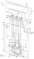
- Figure 1 shows a festooner 1 according to a first exemplary embodiment of the invention.
- the festooner 1 is used for temporarily accumulating or buffering the strip S between the continuous extrusion process of an extruder (not shown) and a discontinuous cutting or application process.
- the strip S can be used in tire building.
- the strip S is a gum strip that wrapped or folded around the sharp edges of a breaker ply to prevent that said sharp edges cut into other parts of the tire.
- the strip S can be used for forming tire components through strip-winding.
- the festooner 1 comprises a base 10 for placement of the festooner 1 on a ground surface, i.e. a factory floor, and a frame or a column 11 standing upright from said base 10.
- the festooner 1 further comprises a first holder 21 and a second holder 22 which are movable opposite to each other along the column 11, i.e. towards and away from each other, in a buffer direction B.
- the first holder 21 and the second holder 22 may comprise a bar-like body extending transverse or perpendicular to the buffer direction B.
- the buffer direction B is parallel or substantially parallel to the column 11.
- the buffer direction B is vertical or substantially vertical.
- the first holder 21 and the second holder 22 extend in a festooner plane A parallel to the buffer direction B.
- the festooner 1 is provided with a first set of buffer rollers 41 and a second set of buffer rollers 42 held by or mounted to the first holder 21 and the second holder 22, respectively.
- the buffer rollers of the first set of buffer rollers 41 are distributed over the first holder 21 at equal intervals.
- the first set of buffer rollers 41 and the second set of buffer rollers 42 define a first buffer path P1 between them that meanders, i.e. that travels or extends alternatingly a buffer roller of the first set of buffer rollers 41 and a buffer roller of the second set of buffer rollers 42.
- the first buffer path P1 coincides or substantially coincides with a first part of the path travelled by the strip S through the festooner 1.
- the first buffer path P1 extends in a first buffer plane parallel to the festooner plane A.
- the festooner 1 further comprises a plurality of first shafts 40 for mounting the first set of buffer rollers 41 and the second set of buffer rollers 42 to the first holder 21 and the second holder 22, respectively.
- the first shafts 40 extend transverse or perpendicular to the festooner plane A.
- Each buffer roller of the first set of buffer rollers 41 and the second set of buffer rollers 42 is fixed to a respective one of the first shafts 40 so as to rotate together with said one first shaft 40.
- the first shafts 40 are hollow.
- the festooner 1 is further provided with a third set of buffer rollers 43 and a fourth set of buffer rollers 44 held by or mounted to the first holder 21 and the second holder 22, respectively, to define a second buffer path P2 between them that meanders, i.e. that travels or extends alternatingly a buffer roller of the third set of buffer rollers 43 and a buffer roller of the fourth set of buffer rollers 44.
- the second buffer path P2 coincides or substantially coincides with a second part of the path travelled by the strip S through the festooner 1.
- the second buffer path P2 extends in a second buffer plane parallel to the festooner plane A and spaced apart from the first buffer plane.
- the festooner 1 further comprises a plurality of second shafts 50 for mounting the third set of buffer rollers 43 and the fourth set of buffer rollers 44.
- Each second shaft 50 of the plurality of second shafts 50 extends concentrically through a respective first shaft 40 of the plurality of first shafts 40.
- the second shafts 50 protrude from the first shafts 40 to support the third set of buffer rollers 43 and the fourth set of buffer rollers 44.
- Each buffer roller of the third set of buffer rollers 43 and the fourth set of buffer rollers 44 is fixed to the protruding part of a respective one of the second shafts 50 so as to rotate together with said one second shaft 50.
- the third set of buffer rollers 43 and a fourth set of buffer rollers 44 can be mounted or positioned coaxially with respect to the first set of buffer rollers 41 and the second set of buffer rollers 42, respectively.
- the second buffer path P2 can thus be a copy of the first buffer path P1, preferably extending parallel to each other in the first buffer plane and the second buffer plane, respectively.
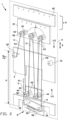
- the festooner 1 further comprises a transfer member 9 for transferring the strip S from the first buffer path P1, as shown in figure 1 , to the second buffer path P2, as shown in figure 2 , along a transfer path T extending obliquely to the festooner plane A.
- the transfer member 9 comprises a set of transfer rollers 91 for receiving the strip S from the first buffer path P1 and for outputting the strip S into the second buffer path P2.
- the set of transfer rollers 91 are positioned obliquely with respect to the festooner plane A.
- the strip S is twisted slightly in the transition from the last of the buffer rollers 41 associated with the first buffer path P1 to one of said transfer rollers 91 and in the transition from one of said transfer rollers 91 to the first of the buffer rollers 43 associated with the second buffer path P2.
- the transfer member 9 further comprises a transfer conveyor 92 extending obliquely to the festooner plane A, in particular parallel or substantially parallel to the transfer path T.
- the transfer conveyor 92 comprises an endless belt.
- the festooner 1 further comprises an intermediate member 3 for guiding the strip S into and out of the festooner 1, i.e. into the first buffer path P1 and out of the second buffer path P2.
- the intermediate member 3 may comprise a bar-like body extending transverse or perpendicular to the buffer direction B.
- the intermediate member 3 is positioned relative to the base 10 such that the intermediate member 3 extends at a height H above the ground surface in a range of fifty centimeters to one-hundred-and-eighty centimeters, preferably one-hundred centimeters to one-hundred-and-eighty centimeters, more preferably one-hundred-and-twenty centimeters to one-hundred-and-sixty centimeters.
- a platform may be used for ergonomic access when the intermediate member 3 is positioned higher.
- the festooner 1 is provided with an entry roller 31 and an exit roller 32 held by the intermediate member 3 to guide the strip S into the first buffer path P1 and out of the second buffer path P2, respectively.
- Figures 1 and 2 show the first holder 21 and the second holder 22 in a first outer position and a second outer position, respectively, maximally spaced apart from the intermediate member 3 in the buffer direction B.
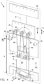
- Figures 3 and 4 show the situation after the first holder 21 and the second holder 22 have been moved towards each other in the buffer direction B into a first loading position and a second loading position, respectively, as close as possible to, directly adjacent to and/or on opposite sides of the intermediate member 3.
- the strip S can be conveniently guided along the first buffer path P1 and the second buffer path P2 at a height H that is ergonomic for an operator.
- the operator does not have to reach up and down over long distances to manually load the strip S into the festooner 1.
- the festooner 1 further comprises a first endless drive element 51 that extends at least partially alongside the first buffer path P1 to drive the first set of buffer rollers 41 and the second set of buffer rollers 42.
- the first drive element 51 extends in a loop and at least a part of said loop extends alongside the first buffer path P1.
- the first drive element 51 has a constant or substantially constant length.
- the first endless drive element 51 is schematically represented by a dashed line.
- the festooner 1 is provided with one or more first drives 55 for causing the first endless drive element 51 to move at the same speed or substantially the same speed as the strip S, i.e. based on the speed of the strip S at the entry and/or exit of the first buffer path P1 and/or based on the extrusion speed of the extruder and/or based on the speed of the strip S at a downstream station, i.e. the cutter.
- Using more than one first drive 55 at different locations along the first buffer path P1 may reduce looseness of the first endless drive element 51 as a result of tolerance build-up.
- the first endless drive element 51 runs along the first buffer path P1 in the same direction as the strip S and ultimately departs from the first buffer path P1.
- the first endless drive element 51 is then returned to the start of the first buffer path P1 through another section of the festooner 1 to complete the loop.
- the first endless drive element 51 is a chain.
- a drive belt, timing belt or the like may be used.
- the festooner 1 comprises a first set of buffer wheels 71, in particular sprocket wheels, that engage with the first endless drive element 51 to be driven by said first endless drive element 51.
- Each buffer wheel of the first set of buffer wheels 71 is coaxially mounted to and/or rotatable together with a respective one of the buffer rollers of the first set of buffer rollers 41 and the second set of buffer roller 42 or one of the entry roller 31 and the exit roller 32.
- the first set of buffer wheels 71 is held coaxially with the first set of buffer rollers 41 and the second set of buffer rollers 42 on the plurality of first shafts 40.
- the first set of buffer wheels 71 When the first set of buffer wheels 71 is driven in rotation by the first endless drive element 51, the first set of buffer rollers 41, the second set of buffer rollers 42, the entry roller 31 and the exit roller 32 are rotated as well.
- the diameter of the first set of buffer wheels 71 is chosen so as to support the first endless drive element 51 at the same or substantially the same radius at which the strip S is supported on the first set of buffer rollers 41, the second set of buffer rollers 42, and the entry roller 31.
- the festooner 1 further comprises a second endless drive element 52, similar to the first endless drive element 51, that extends at least partially alongside the second buffer path P2 to drive the third set of buffer rollers 43 and the fourth set of buffer rollers 44.
- the second endless drive element 52 runs along the second buffer path P2 in the same direction as the strip S and ultimately departs from the second buffer path P2.
- the second endless drive element 52 is then returned to the start of the second buffer path P2 through another section of the festooner 1 to complete the loop.
- the second endless drive element 52 is schematically represented by a solid line.
- the second endless drive element 52 like the first endless drive element 51, is a chain.
- a drive belt, timing belt or the like may be used.
- the festooner 1 comprises a second set of buffer wheels 72, in particular sprocket wheels, that engage with the second endless drive element 52 to be driven by said second endless drive element 52.
- Each buffer wheel of the second set of buffer wheels 72 is coaxially mounted to and/or rotatable together with a respective one of the buffer rollers of the third set of buffer rollers 43 and the fourth set of buffer roller 44 and the exit roller 32.
- the second set of buffer wheels 72 is held coaxially with the third set of buffer rollers 43 and the fourth set of buffer rollers 44 on the plurality of second shafts 50.
- first set of buffer rollers 41, the second set of buffer rollers 42, the third set of buffer rollers 43 and the fourth set of buffer rollers 44 are located at a first side of the festooner plane A, and wherein the first set of buffer wheels 71 and the second set of buffer wheels 72 are located at a second side of the festooner plane A, opposite to the first side.
- the plurality of first shafts 40 and the plurality of second shafts 50 extend through the respective holders 21, 22 to the other side of the festooner plane A.
- Each second shaft 50 extends through a respective one of the first shafts 40 and protrudes out of the respective first shaft 40 to carry the respective buffer wheel of the second set of buffer wheels 72 in a coaxial relationship to the respective buffer wheel of the first set of buffer wheels 71 on the respective first shaft 40.
- the festooner 1 comprises a coupling member 80 for coupling the first endless drive element 51 to the second endless drive element 52.
- the second endless drive element 52 can be driven by its own, one or more dedicated drives (not shown), which can be electronically coupled to the one or more first drives 55, for example via a control unit, to run at the same speed or at slightly different speeds.
- the coupling member 80 comprises a third endless drive element 53, preferably a chain, that engages onto two first coupling wheels 81, in particular sprocket wheels, that are coaxially coupled to one buffer wheel of the first set of buffer wheels 71 and one buffer wheel of the second set of buffer wheels 72 so as to rotate together with said respective buffer wheels 71, 72.
- the third endless drive element 53 is schematically represented by a dashed line.
- the first endless drive element 51 and the second endless drive element 52 are coupled in a 1:1 transmission ratio.
- a non-equal transmission ratio may be chosen, for example for stretching or compressing the strip S in the second buffer path P2.
- the coupling member 80 further comprises one or more second coupling wheels 82, preferably sprocket wheels, that guide the third endless drive element 53 along an U-shaped path.
- the festooner 1 further comprises a tension balancer 8 for balancing tensioning between the first endless drive element 51 and the second endless drive element 52.
- the tension balancer 8 comprises a guide 85 for each endless drive element 51, 52.
- the guide 85 is movable in a direction with at least a component or a vector component in the buffer direction B.
- the guide 85 is movable over a rail 86 that is mounted to the intermediate member 3.
- One buffer wheel of the first set of buffer wheels 71 and the second set of buffer wheels 72 is mounted to said guide 85 to move with said guide 85 in the buffer direction B.
- the coupling member 80 is coupled to each one of the guides 85, wherein at least a part of the weight of the coupling member 80 pulls down on the guides 85 in the buffer direction B.
- the festooner 1 may further comprises a fourth endless drive element 54, preferably a chain, to couple the transfer conveyor 92 and the transfer rollers 91, so that they can all be driven by the same second drive 56.
- the fourth endless drive element 54 is schematically represented by a solid line.
- the strip S enters the festooner 1, i.e. at the entry roller 31, with an entry speed V1 and exits the festooner 1, i.e. at the exit roller 32, with an exit speed V2.
- the buffer capacity of the festooner 1 can be changed by moving the first holder 21 and the second holder 22 oppositely in the buffer direction B.
- the speed at which the capacity changes is schematically shown with speed arrow V3 parallel to the buffer direction B.
- the speed at which each buffer roller of the sets of buffer rollers 41-44 is driven is equal or substantially equal to the speed of the strip S at the respective buffer roller.
- the first endless drive element 51 and the second endless drive element 52 will automatically cause each buffer roller of the sets of buffer rollers 41-44 to change its rotational speed in response to a change in capacity of the festooner 1.
- each buffer roller of the sets of buffer rollers 41-44 can be driven automatically at the right speed by the first endless drive element 51 and the second endless drive element 52 in response to a change in entry speed V1, exit speed V2, the capacity change speed V3 and the position of the respective buffer roller within the festooner 1.
- Figures 1 and 2 show the festooner 1 at maximum capacity.
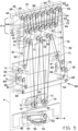
- Figures 3 and 4 show the same festooner 1 at minimum capacity. It will be appreciated that the length of the first buffer path P1 and the second buffer path P2 when the festooner 1 is at maximum capacity is considerably longer than the length of the first buffer path P1 and the second buffer path P2 when the festooner 1 is at minimum capacity.
- the length of the first endless drive element 51 and the second endless drive element 52 travelling along the first buffer path P1 and the second buffer path P2, respectively, is varied with the same amount, while the overall length of the first endless drive element 51 and the second endless drive elements 52 remains the same.
- the festooner 1 At minimum capacity of the festooner 1, considerable overlengths of the first endless drive element 51 and the second endless drive element 52 needs to be temporarily collected. To this end, the festooner 1 is provided with an overlength collector 6 for collecting and paying out (or off-load) the overlengths of the first endless drive element 51 and the second endless drive element 52.
- the overlength collector 6 is located in the buffer direction B at one side of the first buffer path P1 only.
- the overlength collector 6 is located in the buffer direction B at a side of the first set of buffer rollers 41 facing away from the second set of buffer rollers 42.
- the overlength collector 6 is located above the first buffer path P1, the first set of buffer rollers 41 and/or the first holder 21, i.e. at or near the top end of the festooner 1.
- This has the technical advantage that overlength is being collected at one end of the festooner 1 only.
- the resulting festooner 1 can be more compact and/or more ergonomic.
- the overlength collector 6 when the overlength collector 6 is located at or near the top of the festooner 1, the part of the festooner 1 that buffers the strip S can be located closer to the ground surface. Conveniently, the previously mentioned height H of the intermediate member 3 above the ground surface can be obtained, so that - despite the presence of the overlength collector 6 - the strip S can be loaded ergonomically into the festooner 1.
- the overlength collector 6 comprises a first set of collector wheels 61 and a second set of collector wheels 62 that define a meandering first collector path C1 between them.
- the first collector path C1 travels or extends alternatingly along a wheel of the first set of collector wheels 61 and a wheel of the second set of collector wheels 62.
- the first collector path C1 coincides or substantially coincides with the path travelled by the first endless drive element 51 through the overlength collector 6.
- the first collector path C1 like the first buffer path P1, comprises a plurality of second line segments extending between the collector wheels of the first set of collector wheels 61 and the second set of collector wheels 62.
- the second line segments are bitangent to the pair of collector wheels it interconnects. More specifically, each second line segment extends as an outer tangent between a pair of collector wheels of the first set of collector wheels 61 and the second set of collector wheels 62.
- the first set of collector wheels 61 and the second set of collector wheels 62 are sprocket wheels that can engage with the first endless drive element 51 in the form of a chain.
- the first set of collector wheels 61 is held by or mounted to the first holder 21.
- the overlength collector 6 further comprises a collector frame 60 that is arranged to remain stationary in the buffer direction B while the first holder 21 moves.
- the collector frame 60 is mounted to the column 11 at or near the top end of the festooner 1.
- the second set of collector wheels 62 is mounted to said collector frame 60.
- the first set of collector wheels 61 and the second set of collector wheels 62 are mounted to the first holder 21 and the collector frame 60, respectively, via a plurality of third shafts 65. Like the first shafts 40, said third shafts 65 are hollow.
- the length increase or decrease of the first endless drive element 51 in the overlength collector 6, i.e. in the first collector path C1 is defined by the relative movement between the first set of collector wheels 61 and the second set of collector wheels 62 in the buffer direction B. Said relative movement is generated by the movement of the first holder 21 in the buffer direction B.
- the length increase or decrease of the first endless drive element 51 in the first buffer path P1 is defined by the opposite movements of the first holder 21 and the second holder 22 in the buffer direction B.
- the change in distance between the first holder 21 and the second holder 22 during their respective opposite movements is twice the change in distance between the first holder 21 and the collector frame 60.
- the number of collector wheels of the first set of collector wheels 61 is twice the number of buffer wheels of the first set of buffer wheels 71.
- the number of second line segments is twice the number of first line segments. Consequently, when the first holder 21 is moved in the buffer direction B, the length of the first endless drive element 51 is increased or decreased over a number of second line segments that is twice the number of first line segments.
- the first collector path C1 to collect an overlength of the first endless drive element 51 that is equal or substantially to the decrease of the length of the first endless drive element 51 extending along the first buffer path P1 when the festooner 1 is at minimum capacity, and conversely to pay out or off load an overlength equal or substantially equal to the increase of the length of the first endless drive element 51 extending along the first buffer path P1 when the festooner 1 moves towards maximum capacity.
- the first collector path C1 can be increased or decreased with the same amount that the first buffer path P1 is decreased or increased as a result of the opposite movement of both the first holder 21 and the second holder 22 in the buffer direction B.
- the overlength collector 6 further comprises a third set of collector wheels 63 and a fourth set of collector wheels 64 that define a meandering second collector path C2 between them, similar to the first collector path C1.
- the second collector path C2 travels or extends alternatingly along a wheel of the third set of collector wheels 63 and a wheel of the fourth set of collector wheels 64. It will be clear that the second collector path C2 coincides or substantially coincides with the path travelled by the second endless drive element 52 through the overlength collector 6.
- the third set of collector wheels 63 and the fourth set of collector wheels 64 are arranged in a coaxial relationship to the first set of collector wheels 61 and the second set of collector wheels 62, respectively, on a plurality of fourth shafts 66.
- the fourth shafts 66 extend concentrically within and/or extend through the third shafts 65.
- the second collector path C2 can thus be a copy of the first collector path C1, preferably extending parallel to each other.
- the length of the second collector path C2 can be increased or decreased in the same way as and/or simultaneously with the length change of the first collector path C1. This allows the second collector path C2 to collect an overlength of the second endless drive element 52 that is equal or substantially to the decrease of the length of the second endless drive element 52 extending along the second buffer path P2 when the festooner 1 is at minimum capacity, and conversely to pay out or off load an overlength equal or substantially equal to the increase of the length of the second endless drive element 52 extending along the second buffer path P2 when the festooner 1 moves towards maximum capacity.
- FIG. 6 shows an alternative festooner 101 according to a second exemplary embodiment of the invention, which differs from the aforementioned festooner 1 only in that its balancer 108 has a rotatable guide 185 for each endless drive element 51, 52.
- Each guide 185 is movable like a seesaw about a rotation axis R and carries one buffer wheel 71, 72 from the respective set of buffer wheels and a first coupling wheel 81 on opposite sides of the rotation axis R.
- each guide 185 is support by a central hinge member 186 at the rotation axis R.
- the guides 185 are interconnected by the coupling member 80 in the form of the third endless drive element 53 that engages both first coupling wheels 81.
- the first endless drive element 51 engages with the guide 185 carrying the first buffer wheel 71 and the second endless drive element 52 engages with the guide 185 carrying the second buffer wheel 72. Consequently, when the guide 185 that is associated with the first endless drive element 51 is pulled upwards with a component in the buffer direction B as a result of tension in said first endless drive element 51, the seesaw movement of the first guide 185 is transmitted through the third endless drive element 53 to the other guide 185, which responds with a seesaw movement of its own to relieve tension in the second endless drive element 52 in an upward direction. As a result, the tension between the first endless drive element 51 and the second endless drive element 52 can be balanced out.
- the alternative festooner 101 is further provided with one or more dampeners 188, for example a pneumatic cylinder or a spring, to dampen minor vibrations or fluctuations in the endless drive elements 51, 52.
- the one or more dampeners 188 are configured to support the respective guides 185.
- the one or more dampeners 188 may alternative be associated with one or more of the buffer wheels 71, 72.
- the one or more dampeners 188 may also be applied to the festooner 1 of the previous embodiment in a similar manner.
- a method for buffering a strip S using the aforementioned festooners 1, 101 will now be briefly discussed with reference to figures 1-6 .
- the method comprises the steps of:
- the method may further comprise the steps of:
- the first holder 21 and the second holder 22 can be moved in the buffer direction B towards each other into a first loading position and a second loading position, respectively, as shown in figures 3 and 4 .
- the strip S can subsequently be manually guided through the festooner 1 along the first buffer path P1 and the second buffer path P2, while the first holder 21 and the second holder 22 are conveniently located at an ergonomic working height in close proximity to, i.e. directly above and below, the intermediate member 3.
- the previously discussed festooner 1 has the benefit that speed differences between the strip S and the festooner 1, and as a result thereof tensile forces in the strip S, can be reduced to a minimum.
- the forces exerted on the strip S can be reduced or prevented to such an extent that the strip S can be guided through the festooner 1 without a liner, i.e. in direct contact with the rollers of the festooner 1.
- This is particularly relevant for thin or hot strips, such as gum strips used in tire building, because said strips can be easily deformed. Without a liner, the buffering process is less costly and more durable, because there is less waste.
- the invention relates to a festooner 1 and a method for buffering a strip S, the festooner 1 comprising a first set of buffer rollers 41 and a second set of buffer rollers 42, wherein the first set of buffer rollers 41 and the second set of buffer rollers 42 define a meandering first buffer path P1 between them, wherein the festooner 1 further comprises a first endless drive element 51 for driving the first set of buffer rollers 41 and the second set of buffer rollers 42, wherein the festooner 1 further comprises a third set of buffer rollers 43 and a fourth set of buffer rollers 44 coaxial to the first set of buffer rollers 41 and the second set of buffer rollers 42, respectively, defining a meandering second buffer path P2 between them, wherein the festooner 1 further comprises a second endless drive element 52 for driving the third set of buffer rollers 43 and the fourth set of buffer rollers 44.
Landscapes
- Engineering & Computer Science (AREA)
- Mechanical Engineering (AREA)
- Controlling Rewinding, Feeding, Winding, Or Abnormalities Of Webs (AREA)
- Folding Of Thin Sheet-Like Materials, Special Discharging Devices, And Others (AREA)
- Tyre Moulding (AREA)
- Advancing Webs (AREA)
Claims (20)
- Streifenleger (1) zum Puffern eines Streifens (S), wobei der Streifenleger einen ersten Halter (21) und einen zweiten Halter (22) aufweist, wobei mindestens einer des ersten Halters und des zweiten Halters zu dem anderen des ersten Halters und des zweiten Halters hin und von diesem weg in einer Pufferrichtung (B) bewegbar ist, um die Pufferkapazität des Streifenlegers zu variieren, wobei der Streifenleger ferner einen ersten Satz von Pufferwalzen (41) und einen zweiten Satz von Pufferwalzen (42) aufweist, die von dem ersten Halter bzw. dem zweiten Halter gehalten werden, wobei der erste Satz von Pufferwalzen und der zweite Satz von Pufferwalzen einen mäanderförmigen ersten Pufferpfad (P1) zwischen sich definieren, der sich abwechselnd entlang einer Pufferwalze des ersten Satzes von Pufferwalzen und einer Pufferwalze des zweiten Satzes von Pufferwalzen erstreckt, wobei der Streifenleger ferner einen dritten Satz von Pufferwalzen (43) und einen vierten Satz von Pufferwalzen (44) aufweist, die koaxial zu dem ersten Satz von Pufferwalzen bzw. dem zweiten Satz von Pufferwalzen angeordnet sind, die einen mäanderförmigen zweiten Pufferpfad zwischen sich definieren, der sich abwechselnd entlang einer Pufferwalze des dritten Satzes von Pufferwalzen und einer Pufferwalze des vierten Satzes von Pufferwalzen erstreckt,
dadurch gekennzeichnet, dassder Streifenleger (1) ferner ein erstes endloses Antriebselement (51) zum Antreiben des ersten Satzes von Pufferwalzen (41) und des zweiten Satzes von Pufferwalzen (42) aufweist,wobei der Streifenleger (1) ferner ein zweites endloses Antriebselement (52) zum Antreiben des dritten Satzes von Pufferwalzen (43) und des vierten Satzes von Pufferwalzen (44) aufweist. - Streifenleger nach Anspruch 1, wobei der Streifenleger eine Mehrzahl von ersten Wellen (40) zum Anbringen des ersten Satzes von Pufferwalzen und des zweiten Satzes von Pufferwalzen aufweist, wobei der Streifenleger ferner eine Mehrzahl von zweiten Wellen (50) zum Anbringen des dritten Satzes von Pufferwalzen (43) und des vierten Satzes von Pufferwalzen (44) aufweist,wobei die Mehrzahl von ersten Wellen hohl ist, und wobei sich jede zweite Welle der Mehrzahl von zweiten Wellen konzentrisch durch eine jeweilige erste Welle der Mehrzahl von ersten Wellen erstreckt,wobei bevorzugt der Streifenleger einen ersten Satz von Pufferrädern (71) und einen zweiten Satz von Pufferrädern (72) aufweist, die an die Mehrzahl von ersten Wellen bzw. die Mehrzahl von zweiten Wellen gekoppelt sind, das erste endlose Antriebselement (51) zum Eingreifen mit dem ersten Satz von Pufferrädern (71) ausgebildet ist, und das zweite endlose Antriebselement (52) zum Eingreifen mit dem zweiten Satz von Pufferrädern (72) ausgebildet ist, wobei bevorzugt der erste Halter (21) und der zweite Halter (22) sich in einer Streifenlegerebene parallel zu der Pufferrichtung erstrecken, wobei der erste Satz von Pufferwalzen, der zweite Satz von Pufferwalzen, der dritte Satz von Pufferwalzen und der vierte Satz von Pufferwalzen an einer ersten Seite der Streifenlegerebene (A) positioniert sind, und wobei der erste Satz von Pufferrädern und der zweite Satz von Pufferrädern an einer zweiten Seite der Streifenlegerebene entgegensetzt zu der ersten Seite positioniert sind.
- Streifenleger nach einem der vorstehenden Ansprüche, wobei der Streifenleger einen ersten Antrieb zum Antreiben eines des ersten endlosen Antriebselements (51) und des zweiten endlosen Antriebselements und ein Koppelelement (80) zum Koppeln des ersten endlosen Antriebselements an das zweite endlose Antriebselement aufweist, wobei bevorzugt das Koppelelement ein drittes endloses Antriebselement (53) aufweist.
- Streifenleger nach einem der vorstehenden Ansprüche, wobei der Streifenleger ferner einen Spannungsausgleich (8) zum Ausgleichen der Spannung zwischen dem ersten endlosen Antriebselement (51) und dem zweiten endlosen Antriebselement (52) aufweist, wobei bevorzugt der Streifenleger eine Mehrzahl von ersten Wellen zum Anbringen des ersten Satzes von Pufferwalzen und des zweiten Satzes von Pufferwalzen aufweist,
wobei der Streifenleger ferner eine Mehrzahl von zweiten Wellen zum Anbringen des dritten Satzes von Pufferwalzen und des vierten Satzes von Pufferwalzen aufweist, wobei die Mehrzahl von ersten Wellen hohl ist und wobei jede zweite Welle der Mehrzahl von zweiten Wellen sich konzentrisch durch eine jeweilige erste Welle der Mehrzahl von ersten Wellen erstreckt, wobei der Streifenleger einen ersten Satz von Pufferrädern und einen zweiten Satz von Pufferrädern aufweist, die an die Mehrzahl von ersten Wellen bzw. die Mehrzahl von zweiten Wellen gekoppelt sind, wobei das erste endlose Antriebselement zum Eingreifen mit dem ersten Satz von Pufferrädern (71) ausgebildet ist und das zweite endlose Antriebselement (52) zum Eingreifen mit dem zweiten Satz von Pufferräder ausgebildet ist, wobei der Spannungsausgleich eine oder mehrere Führungen (85) aufweist, die in einer Richtung mit mindestens einer Komponente in der Pufferrichtung bewegbar sind, wobei mindestens ein Pufferrad des ersten Satzes von Pufferrädern und/oder des zweiten Satzes von Pufferrädern an der einen oder den mehreren Führungen angebracht ist und sich mit der einen oder den mehreren Führungen in der Pufferrichtung bewegt, wobei mehr bevorzugt der Streifenleger einen ersten Antrieb zum Antreiben eines des ersten endlosen Antriebselements und des zweiten endlosen Antriebselements und ein Koppelelement (80) zum Koppeln des ersten endlosen Antriebselements an das zweite endlose Antriebselement aufweist, wobei das Koppelelement ein drittes endloses Antriebselement aufweist, wobei das Koppelelement an die eine oder die mehreren Führungen gekoppelt ist, wobei mindestens ein Teil des Gewichts des Koppelelements an der einen oder den mehreren Führungen (85) in Pufferrichtung nach unten zieht. - Streifenleger nach einem der vorstehenden Ansprüche, wobei der Streifenleger ferner eine oder mehrere Dämpfungselemente zum Dämpfen des ersten endlosen Antriebselements und/oder des zweiten endlosen Antriebselements aufweist.
- Streifenleger nach einem der vorstehenden Ansprüche, wobei der erste Halter und der zweite Halter sich in einer Streifenlegerebene parallel zu der Pufferrichtung erstrecken, wobei der Streifenleger ferner ein Übertragungselement (9) zum Übertragen des Streifens von dem ersten Pufferpfad (P1) zu dem zweiten Pufferpfad (P2) entlang eines Übertragungspfads (T) aufweist, der sich schräg zu der Streifenlegerebene (A) erstreckt, wobei bevorzugt das Übertragungselement einen Satz von Übertragungswalzen (91) zum Empfangen des Streifens von dem ersten Pufferpfad und zum Ausgeben des Streifens in den zweiten Pufferpfad aufweist, wobei der Satz von Übertragungswalzen (91) schräg bezüglich der Streifenlegerebene (A) positioniert ist.
- Streifenleger nach Anspruch 6, wobei der Streifenleger eine Übertragungsfördereinrichtung (92) aufweist, die sich schräg zu der Streifenlegerebene erstreckt, wobei bevorzugt die Übertragungsfördereinrichtung ein endloses Band aufweist.
- Streifenleger nach Anspruch 7, wobei der Streifenleger einen zweiten Antrieb (56) zum Antreiben der Übertragungsfördereinrichtung aufweist.
- Streifenleger nach einem der vorstehenden Ansprüche, wobei der erste Pufferpfad (P1) und der zweite Pufferpfad (P2) parallel oder im Wesentlichen parallel sind.
- Streifenleger nach einem der vorstehenden Ansprüche, wobei das erste endlose Antriebselement (51) und das zweite endlose Antriebselement (52) Ketten sind.
- Streifenleger nach einem der vorstehenden Ansprüche, wobei der erste Halter (21) und der zweite Halter (22) in der Pufferrichtung gegenläufig bewegbar sind, um die Pufferkapazität des Streifenlegers zu variieren.
- Streifenleger nach einem der vorstehenden Ansprüche, wobei der Streifenleger ferner einen Überlängensammler (6) zum Sammeln und Ablaufenlassen von Überlängen des ersten endlosen Antriebselements (51) und des zweiten endlosen Antriebselements (52) als Ergebnis einer Variation der Pufferkapazität des Streifenlegers aufweist, wobei bevorzugt der Überlängensammler (6) in der Pufferrichtung nur an einer Seite des ersten Pufferpfads positioniert ist.
- Streifenleger nach Anspruch 12, wobei der Überlängensammler (6) in der Pufferrichtung an einer Seite des ersten Satzes von Pufferwalzen (41) positioniert ist, die von dem zweiten Satz von Pufferwalzen (52) weg weist.
- Streifenleger nach Anspruch 12 oder 13, wobei der erste Satz von Pufferwalzen (41) oberhalb des zweiten Satzes von Pufferwalzen (42) positioniert ist, wobei der Überlängensammler (6) oberhalb des ersten Satzes von Pufferwalzen positioniert ist.
- Streifenleger nach einem der Ansprüche 12 bis 14, wobei der Überlängensammler (6) einen ersten Satz von Sammlerrädern (61) und einen zweiten Satz von Sammlerrädern (62) aufweist, die einen mäanderförmigen ersten Sammlerpfad zwischen sich definieren, der sich abwechselnd entlang eines Rads des ersten Satzes von Sammlerrädern und eines Rads des zweiten Satzes von Sammlerrädern erstreckt, wobei das erste endlose Antriebselement (51) sich entlang des ersten Sammlerpfads erstreckt.
- Streifenleger nach Anspruch 15, wobei der Überlängensammler (6) einen dritten Satz von Sammlerrädern (63) und einen vierten Satz von Sammlerrädern (64) aufweist, die einen mäanderförmigen zweiten Sammlerpfad zwischen sich definieren, der sich abwechselnd entlang eines Sammlerrads des dritten Satzes von Sammlerrädern (63) und eines Sammlerrads des vierten Satzes von Sammlerrädern (64) erstreckt, wobei das zweite endlose Antriebselement sich entlang des zweiten Sammlerpfads (C2) erstreckt, wobei bevorzugt der Streifenleger eine Mehrzahl von dritten Wellen (65) zum Anbringen des ersten Satzes von Sammlerrädern (61) und des zweiten Satzes von Sammlerrädern (62) aufweist, wobei der Streifenleger ferner eine Mehrzahl von vierten Wellen zum Anbringen des dritten Satzes von Sammlerrädern (63) und des vierten Satzes von Sammlerrädern (64) aufweist, wobei die Mehrzahl von dritten Wellen hohl ist und wobei jede vierte Welle der Mehrzahl von vierten Wellen (66) sich konzentrisch durch eine jeweilige dritte Welle der Mehrzahl von dritten Wellen erstreckt.
- Streifenleger nach Anspruch 16, wobei der erste Sammlerpfad (C1) und der zweite Sammlerpfad (C2) parallel oder im Wesentlichen parallel sind.
- Verfahren zum Puffern eines Streifens unter Verwendung eines Streifenlegers nach einem der vorstehenden Ansprüche, wobei das Verfahren die folgenden Schritte aufweist:- Führen eines Streifens (S) durch den Streifenleger entlang des ersten Pufferpfads (P1);- Übertragen des Streifens von dem ersten Pufferpfad zu dem zweiten Pufferpfad (P2);- Führen des Streifens durch den zweiten Pufferpfad (P2) ;- Antreiben des ersten Satzes von Pufferwalzen (42) und des zweiten Satzes von Pufferwalzen (42) mit dem ersten endlosen Antriebselement (51); und- Antreiben des dritten Satzes von Pufferwalzen (43) und des vierten Satzes von Pufferwalzen (44) mit dem zweiten endlosen Antriebselement.
- Verfahren nach Anspruch 18, wobei das Verfahren ferner die folgenden Schritte aufweist:- Variieren der Pufferkapazität des Streifenlegers durch Bewegen mindestens eines des ersten Halters (21) und des zweiten Halters (22) zu dem anderen des ersten Halters (21) und des zweiten Halters (22) hin und/oder von dem ersten Halter und dem zweiten Halter in der Pufferrichtung weg; und- Sammeln und/oder Ablaufenlassen von Überlängen des ersten endlosen Antriebselements (51) und des zweiten endlosen Antriebselements (52) mit einem Überlängensammler (6) in Reaktion auf das Variieren der Pufferkapazität.
- Verfahren nach Anspruch 18 oder 19, wobei der Streifen (S) durch den Streifenleger ohne Verwendung einer Tragschicht zum Tragen des Streifens relativ zu den Pufferwalzen (41-44) geführt wird.
Priority Applications (1)
| Application Number | Priority Date | Filing Date | Title |
|---|---|---|---|
| RS20250229A RS66578B1 (sr) | 2021-01-29 | 2022-01-17 | Festoner i postupak za amortizovanje trake |
Applications Claiming Priority (2)
| Application Number | Priority Date | Filing Date | Title |
|---|---|---|---|
| NL2027462A NL2027462B1 (en) | 2021-01-29 | 2021-01-29 | Festooner and method for buffering a strip |
| PCT/NL2022/050013 WO2022164310A1 (en) | 2021-01-29 | 2022-01-17 | Festooner and method for buffering a strip |
Publications (3)
| Publication Number | Publication Date |
|---|---|
| EP4284740A1 EP4284740A1 (de) | 2023-12-06 |
| EP4284740C0 EP4284740C0 (de) | 2024-12-11 |
| EP4284740B1 true EP4284740B1 (de) | 2024-12-11 |
Family
ID=74669499
Family Applications (1)
| Application Number | Title | Priority Date | Filing Date |
|---|---|---|---|
| EP22700689.7A Active EP4284740B1 (de) | 2021-01-29 | 2022-01-17 | Festoner und verfahren zum puffern eines bandes |
Country Status (12)
| Country | Link |
|---|---|
| US (1) | US12115745B2 (de) |
| EP (1) | EP4284740B1 (de) |
| JP (1) | JP7443517B2 (de) |
| KR (1) | KR102714594B1 (de) |
| CN (2) | CN114803636A (de) |
| ES (1) | ES3005216T3 (de) |
| HU (1) | HUE070682T2 (de) |
| NL (1) | NL2027462B1 (de) |
| PL (1) | PL4284740T3 (de) |
| RS (1) | RS66578B1 (de) |
| TW (1) | TW202233399A (de) |
| WO (1) | WO2022164310A1 (de) |
Families Citing this family (2)
| Publication number | Priority date | Publication date | Assignee | Title |
|---|---|---|---|---|
| GB201314313D0 (en) * | 2013-08-09 | 2013-09-25 | Ocado Ltd | Apparatus for retrieving units from a storage system |
| NL2027462B1 (en) * | 2021-01-29 | 2022-09-02 | Vmi Holland Bv | Festooner and method for buffering a strip |
Family Cites Families (26)
| Publication number | Priority date | Publication date | Assignee | Title |
|---|---|---|---|---|
| JPS50134492A (de) | 1974-04-10 | 1975-10-24 | ||
| US4009814A (en) * | 1975-09-08 | 1977-03-01 | Scott Paper Company | Web accumulator |
| JPH0356686Y2 (de) | 1984-11-02 | 1991-12-20 | ||
| US6473669B2 (en) | 1998-07-03 | 2002-10-29 | Kimberly-Clark Worldwide, Inc. | Controlling web tension, and accumulating lengths of web, by actively controlling velocity and acceleration of a festoon |
| US6425547B1 (en) | 1999-08-31 | 2002-07-30 | Ethicon | System and method for producing coreless fabric rolls |
| KR100441949B1 (ko) | 2001-11-23 | 2004-07-27 | 한국타이어 주식회사 | 스트립 변형방지를 위한 페스투너의 구조 |
| JP2004210849A (ja) | 2002-12-27 | 2004-07-29 | Sumitomo Bakelite Co Ltd | 半導体封止用エポキシ樹脂組成物及び半導体装置 |
| JP2004210489A (ja) | 2003-01-06 | 2004-07-29 | Bridgestone Corp | 線状体の一時貯留方法および装置 |
| CN100509370C (zh) | 2007-11-23 | 2009-07-08 | 天津市橡塑机械研究所有限公司 | 一种窄冠带部件缠贴机 |
| JP5249596B2 (ja) | 2008-02-04 | 2013-07-31 | 住友ゴム工業株式会社 | ゴムストリップ搬送装置 |
| NL2001509C2 (nl) | 2008-04-23 | 2009-10-26 | Vmi Epe Holland | Inrichting voor het wikkelen van een strip op een bandenbouwtrommel. |
| US20130284786A1 (en) * | 2012-04-25 | 2013-10-31 | Continental Reifen Deutschland Gmbh | Twin rod festoon roll |
| RU2673286C2 (ru) * | 2013-08-05 | 2018-11-23 | Пирелли Тайр С.П.А. | Способ и устройство для управления подачей непрерывного удлиненного элемента в технологическом процессе сборки шин для колес транспортных средств |
| BR112016001674B1 (pt) | 2013-08-05 | 2021-10-05 | Pirelli Tyre S.P.A. | Método e aparelho para controlar o fornecimento de um elemento alongado contínuo em um processo para construir pneus para rodas de veículo |
| JP6181016B2 (ja) | 2014-08-26 | 2017-08-16 | 美津濃株式会社 | シューズのアッパーおよびシューズ |
| WO2016103077A1 (en) * | 2014-12-24 | 2016-06-30 | Pirelli Tyre S.P.A. | Plant for collecting or dispensing an elongated element for building tyres and method for collecting or dispensing an elongated element wound in reels |
| CN205855525U (zh) | 2016-08-09 | 2017-01-04 | 东莞市雅康精密机械有限公司 | 放卷装置及张力控制机构 |
| NL2017819B1 (en) | 2016-11-18 | 2018-05-25 | Vmi Holland Bv | Cutting device and method for a continuous strip into tire components |
| NL2018606B1 (en) * | 2017-03-30 | 2018-10-10 | Vmi Holland Bv | Creel bobbin brake, creel bobbin assembly, a creel and a creel method |
| AU2017420362B2 (en) | 2017-06-23 | 2023-12-21 | Kimberly-Clark Worldwide, Inc. | Tension regulating directly driven roller festoon |
| JP7056054B2 (ja) | 2017-09-25 | 2022-04-19 | 住友ゴム工業株式会社 | ゴムストリップ搬送装置 |
| IT201700112606A1 (it) | 2017-10-06 | 2019-04-06 | Ramina S R L | Accumulatore per un impianto di avvolgimento di bobine di materiale nastriforme e impianto di avvolgimento di bobine di materiale nastriforme dotato di detto accumulatore |
| IT201800006551A1 (it) | 2018-06-21 | 2019-12-21 | Svolgitore per materiale in nastro e metodo per controllare lo svolgimento di materiale in nastro | |
| CN208814399U (zh) * | 2018-09-30 | 2019-05-03 | 南通金轮智能装备研发有限公司 | 一种可变缓冲距离张力装置 |
| CN210709931U (zh) * | 2020-04-13 | 2020-06-09 | 山东华滋自动化技术股份有限公司 | 一种悬臂式同步缓冲装置 |
| NL2027462B1 (en) * | 2021-01-29 | 2022-09-02 | Vmi Holland Bv | Festooner and method for buffering a strip |
-
2021
- 2021-01-29 NL NL2027462A patent/NL2027462B1/en active
-
2022
- 2022-01-17 US US18/275,194 patent/US12115745B2/en active Active
- 2022-01-17 WO PCT/NL2022/050013 patent/WO2022164310A1/en not_active Ceased
- 2022-01-17 KR KR1020237029233A patent/KR102714594B1/ko active Active
- 2022-01-17 ES ES22700689T patent/ES3005216T3/es active Active
- 2022-01-17 PL PL22700689.7T patent/PL4284740T3/pl unknown
- 2022-01-17 JP JP2022529104A patent/JP7443517B2/ja active Active
- 2022-01-17 RS RS20250229A patent/RS66578B1/sr unknown
- 2022-01-17 HU HUE22700689A patent/HUE070682T2/hu unknown
- 2022-01-17 EP EP22700689.7A patent/EP4284740B1/de active Active
- 2022-01-21 TW TW111102700A patent/TW202233399A/zh unknown
- 2022-01-27 CN CN202210112006.2A patent/CN114803636A/zh active Pending
- 2022-01-27 CN CN202220244512.2U patent/CN217147997U/zh active Active
Also Published As
| Publication number | Publication date |
|---|---|
| TW202233399A (zh) | 2022-09-01 |
| ES3005216T3 (en) | 2025-03-14 |
| EP4284740C0 (de) | 2024-12-11 |
| CN114803636A (zh) | 2022-07-29 |
| PL4284740T3 (pl) | 2025-04-22 |
| KR20230135662A (ko) | 2023-09-25 |
| WO2022164310A1 (en) | 2022-08-04 |
| RS66578B1 (sr) | 2025-03-31 |
| KR102714594B1 (ko) | 2024-10-07 |
| US12115745B2 (en) | 2024-10-15 |
| CN217147997U (zh) | 2022-08-09 |
| JP7443517B2 (ja) | 2024-03-05 |
| US20240092599A1 (en) | 2024-03-21 |
| HUE070682T2 (hu) | 2025-06-28 |
| JP2023514909A (ja) | 2023-04-12 |
| EP4284740A1 (de) | 2023-12-06 |
| NL2027462B1 (en) | 2022-09-02 |
Similar Documents
| Publication | Publication Date | Title |
|---|---|---|
| EP1235728B1 (de) | Vorrichtung zum steuern des durchflusses von artikeln | |
| EP4284740B1 (de) | Festoner und verfahren zum puffern eines bandes | |
| US20240083086A1 (en) | Festooner and method for buffering a strip | |
| US20030178284A1 (en) | Article guide for an apparatus for controlling the flow of articles | |
| US6523669B1 (en) | Article guide for an apparatus for controlling the flow of articles | |
| EP0304979B1 (de) | Verpackungsmaschine zum kontinuierlichen Verpacken von Produkten mit wechselnder Höhe | |
| US5597105A (en) | Apparatus for buffering a variable length loop of strip material | |
| CN219057450U (zh) | 带转弯机 | |
| CN107771157B (zh) | 收集装置和用于该收集装置的传送装置 | |
| CN214877593U (zh) | 一种带阻尼无动力辊子机 | |
| CN213325078U (zh) | 一种双层缓存辊道输送装置 | |
| CN112758719B (zh) | 皮带输送机及分路传输装置 | |
| JP3390136B2 (ja) | コンベア | |
| CN112758718B (zh) | 一种可让位调节的皮带输送机及分路传输装置 |
Legal Events
| Date | Code | Title | Description |
|---|---|---|---|
| STAA | Information on the status of an ep patent application or granted ep patent |
Free format text: STATUS: UNKNOWN |
|
| STAA | Information on the status of an ep patent application or granted ep patent |
Free format text: STATUS: THE INTERNATIONAL PUBLICATION HAS BEEN MADE |
|
| PUAI | Public reference made under article 153(3) epc to a published international application that has entered the european phase |
Free format text: ORIGINAL CODE: 0009012 |
|
| STAA | Information on the status of an ep patent application or granted ep patent |
Free format text: STATUS: REQUEST FOR EXAMINATION WAS MADE |
|
| 17P | Request for examination filed |
Effective date: 20230705 |
|
| AK | Designated contracting states |
Kind code of ref document: A1 Designated state(s): AL AT BE BG CH CY CZ DE DK EE ES FI FR GB GR HR HU IE IS IT LI LT LU LV MC MK MT NL NO PL PT RO RS SE SI SK SM TR |
|
| DAV | Request for validation of the european patent (deleted) | ||
| DAX | Request for extension of the european patent (deleted) | ||
| GRAP | Despatch of communication of intention to grant a patent |
Free format text: ORIGINAL CODE: EPIDOSNIGR1 |
|
| STAA | Information on the status of an ep patent application or granted ep patent |
Free format text: STATUS: GRANT OF PATENT IS INTENDED |
|
| INTG | Intention to grant announced |
Effective date: 20240918 |
|
| GRAS | Grant fee paid |
Free format text: ORIGINAL CODE: EPIDOSNIGR3 |
|
| GRAA | (expected) grant |
Free format text: ORIGINAL CODE: 0009210 |
|
| STAA | Information on the status of an ep patent application or granted ep patent |
Free format text: STATUS: THE PATENT HAS BEEN GRANTED |
|
| AK | Designated contracting states |
Kind code of ref document: B1 Designated state(s): AL AT BE BG CH CY CZ DE DK EE ES FI FR GB GR HR HU IE IS IT LI LT LU LV MC MK MT NL NO PL PT RO RS SE SI SK SM TR |
|
| REG | Reference to a national code |
Ref country code: GB Ref legal event code: FG4D |
|
| REG | Reference to a national code |
Ref country code: CH Ref legal event code: EP |
|
| REG | Reference to a national code |
Ref country code: IE Ref legal event code: FG4D |
|
| REG | Reference to a national code |
Ref country code: DE Ref legal event code: R096 Ref document number: 602022008607 Country of ref document: DE |
|
| U01 | Request for unitary effect filed |
Effective date: 20241218 |
|
| U07 | Unitary effect registered |
Designated state(s): AT BE BG DE DK EE FI FR IT LT LU LV MT NL PT RO SE SI Effective date: 20250117 |
|
| U20 | Renewal fee for the european patent with unitary effect paid |
Year of fee payment: 4 Effective date: 20250121 |
|
| REG | Reference to a national code |
Ref country code: ES Ref legal event code: FG2A Ref document number: 3005216 Country of ref document: ES Kind code of ref document: T3 Effective date: 20250314 |
|
| PG25 | Lapsed in a contracting state [announced via postgrant information from national office to epo] |
Ref country code: HR Free format text: LAPSE BECAUSE OF FAILURE TO SUBMIT A TRANSLATION OF THE DESCRIPTION OR TO PAY THE FEE WITHIN THE PRESCRIBED TIME-LIMIT Effective date: 20241211 |
|
| PGFP | Annual fee paid to national office [announced via postgrant information from national office to epo] |
Ref country code: ES Payment date: 20250203 Year of fee payment: 4 |
|
| PG25 | Lapsed in a contracting state [announced via postgrant information from national office to epo] |
Ref country code: NO Free format text: LAPSE BECAUSE OF FAILURE TO SUBMIT A TRANSLATION OF THE DESCRIPTION OR TO PAY THE FEE WITHIN THE PRESCRIBED TIME-LIMIT Effective date: 20250311 |
|
| REG | Reference to a national code |
Ref country code: SK Ref legal event code: T3 Ref document number: E 46059 Country of ref document: SK |
|
| PG25 | Lapsed in a contracting state [announced via postgrant information from national office to epo] |
Ref country code: GR Free format text: LAPSE BECAUSE OF FAILURE TO SUBMIT A TRANSLATION OF THE DESCRIPTION OR TO PAY THE FEE WITHIN THE PRESCRIBED TIME-LIMIT Effective date: 20250312 |
|
| PGFP | Annual fee paid to national office [announced via postgrant information from national office to epo] |
Ref country code: CZ Payment date: 20250102 Year of fee payment: 4 |
|
| PGFP | Annual fee paid to national office [announced via postgrant information from national office to epo] |
Ref country code: SK Payment date: 20250107 Year of fee payment: 4 |
|
| PGFP | Annual fee paid to national office [announced via postgrant information from national office to epo] |
Ref country code: RS Payment date: 20250103 Year of fee payment: 4 |
|
| PGFP | Annual fee paid to national office [announced via postgrant information from national office to epo] |
Ref country code: TR Payment date: 20250109 Year of fee payment: 4 |
|
| REG | Reference to a national code |
Ref country code: HU Ref legal event code: AG4A Ref document number: E070682 Country of ref document: HU |
|
| PG25 | Lapsed in a contracting state [announced via postgrant information from national office to epo] |
Ref country code: SM Free format text: LAPSE BECAUSE OF FAILURE TO SUBMIT A TRANSLATION OF THE DESCRIPTION OR TO PAY THE FEE WITHIN THE PRESCRIBED TIME-LIMIT Effective date: 20241211 |
|
| PGFP | Annual fee paid to national office [announced via postgrant information from national office to epo] |
Ref country code: PL Payment date: 20250103 Year of fee payment: 4 |
|
| PG25 | Lapsed in a contracting state [announced via postgrant information from national office to epo] |
Ref country code: IS Free format text: LAPSE BECAUSE OF FAILURE TO SUBMIT A TRANSLATION OF THE DESCRIPTION OR TO PAY THE FEE WITHIN THE PRESCRIBED TIME-LIMIT Effective date: 20250411 |
|
| REG | Reference to a national code |
Ref country code: CH Ref legal event code: PL |
|
| PG25 | Lapsed in a contracting state [announced via postgrant information from national office to epo] |
Ref country code: MC Free format text: LAPSE BECAUSE OF FAILURE TO SUBMIT A TRANSLATION OF THE DESCRIPTION OR TO PAY THE FEE WITHIN THE PRESCRIBED TIME-LIMIT Effective date: 20241211 |
|
| PLBE | No opposition filed within time limit |
Free format text: ORIGINAL CODE: 0009261 |
|
| STAA | Information on the status of an ep patent application or granted ep patent |
Free format text: STATUS: NO OPPOSITION FILED WITHIN TIME LIMIT |
|
| PG25 | Lapsed in a contracting state [announced via postgrant information from national office to epo] |
Ref country code: CH Free format text: LAPSE BECAUSE OF NON-PAYMENT OF DUE FEES Effective date: 20250131 |
|
| 26N | No opposition filed |
Effective date: 20250912 |
|
| PG25 | Lapsed in a contracting state [announced via postgrant information from national office to epo] |
Ref country code: IE Free format text: LAPSE BECAUSE OF NON-PAYMENT OF DUE FEES Effective date: 20250117 |
|
| PGFP | Annual fee paid to national office [announced via postgrant information from national office to epo] |
Ref country code: HU Payment date: 20260123 Year of fee payment: 5 |
|
| U20 | Renewal fee for the european patent with unitary effect paid |
Year of fee payment: 5 Effective date: 20260129 |