EP4284232B1 - Verfahren und vorrichtung zur offset-kompensation - Google Patents
Verfahren und vorrichtung zur offset-kompensation Download PDFInfo
- Publication number
- EP4284232B1 EP4284232B1 EP22702268.8A EP22702268A EP4284232B1 EP 4284232 B1 EP4284232 B1 EP 4284232B1 EP 22702268 A EP22702268 A EP 22702268A EP 4284232 B1 EP4284232 B1 EP 4284232B1
- Authority
- EP
- European Patent Office
- Prior art keywords
- light signal
- light
- housing
- signal
- light source
- Prior art date
- Legal status (The legal status is an assumption and is not a legal conclusion. Google has not performed a legal analysis and makes no representation as to the accuracy of the status listed.)
- Active
Links
Images
Classifications
-
- A—HUMAN NECESSITIES
- A61—MEDICAL OR VETERINARY SCIENCE; HYGIENE
- A61B—DIAGNOSIS; SURGERY; IDENTIFICATION
- A61B5/00—Measuring for diagnostic purposes; Identification of persons
- A61B5/0059—Measuring for diagnostic purposes; Identification of persons using light, e.g. diagnosis by transillumination, diascopy, fluorescence
- A61B5/0075—Measuring for diagnostic purposes; Identification of persons using light, e.g. diagnosis by transillumination, diascopy, fluorescence by spectroscopy, i.e. measuring spectra, e.g. Raman spectroscopy, infrared absorption spectroscopy
-
- G—PHYSICS
- G01—MEASURING; TESTING
- G01J—MEASUREMENT OF INTENSITY, VELOCITY, SPECTRAL CONTENT, POLARISATION, PHASE OR PULSE CHARACTERISTICS OF INFRARED, VISIBLE OR ULTRAVIOLET LIGHT; COLORIMETRY; RADIATION PYROMETRY
- G01J3/00—Spectrometry; Spectrophotometry; Monochromators; Measuring colours
- G01J3/28—Investigating the spectrum
- G01J3/42—Absorption spectrometry; Double beam spectrometry; Flicker spectrometry; Reflection spectrometry
-
- A—HUMAN NECESSITIES
- A61—MEDICAL OR VETERINARY SCIENCE; HYGIENE
- A61B—DIAGNOSIS; SURGERY; IDENTIFICATION
- A61B5/00—Measuring for diagnostic purposes; Identification of persons
-
- A—HUMAN NECESSITIES
- A61—MEDICAL OR VETERINARY SCIENCE; HYGIENE
- A61B—DIAGNOSIS; SURGERY; IDENTIFICATION
- A61B5/00—Measuring for diagnostic purposes; Identification of persons
- A61B5/0059—Measuring for diagnostic purposes; Identification of persons using light, e.g. diagnosis by transillumination, diascopy, fluorescence
- A61B5/0082—Measuring for diagnostic purposes; Identification of persons using light, e.g. diagnosis by transillumination, diascopy, fluorescence adapted for particular medical purposes
- A61B5/0084—Measuring for diagnostic purposes; Identification of persons using light, e.g. diagnosis by transillumination, diascopy, fluorescence adapted for particular medical purposes for introduction into the body, e.g. by catheters
-
- A—HUMAN NECESSITIES
- A61—MEDICAL OR VETERINARY SCIENCE; HYGIENE
- A61B—DIAGNOSIS; SURGERY; IDENTIFICATION
- A61B5/00—Measuring for diagnostic purposes; Identification of persons
- A61B5/08—Measuring devices for evaluating the respiratory organs
- A61B5/083—Measuring rate of metabolism by using breath test, e.g. measuring rate of oxygen consumption
- A61B5/0833—Measuring rate of oxygen consumption
-
- A—HUMAN NECESSITIES
- A61—MEDICAL OR VETERINARY SCIENCE; HYGIENE
- A61B—DIAGNOSIS; SURGERY; IDENTIFICATION
- A61B5/00—Measuring for diagnostic purposes; Identification of persons
- A61B5/08—Measuring devices for evaluating the respiratory organs
- A61B5/083—Measuring rate of metabolism by using breath test, e.g. measuring rate of oxygen consumption
- A61B5/0836—Measuring rate of CO2 production
-
- G—PHYSICS
- G01—MEASURING; TESTING
- G01J—MEASUREMENT OF INTENSITY, VELOCITY, SPECTRAL CONTENT, POLARISATION, PHASE OR PULSE CHARACTERISTICS OF INFRARED, VISIBLE OR ULTRAVIOLET LIGHT; COLORIMETRY; RADIATION PYROMETRY
- G01J3/00—Spectrometry; Spectrophotometry; Monochromators; Measuring colours
-
- G—PHYSICS
- G01—MEASURING; TESTING
- G01J—MEASUREMENT OF INTENSITY, VELOCITY, SPECTRAL CONTENT, POLARISATION, PHASE OR PULSE CHARACTERISTICS OF INFRARED, VISIBLE OR ULTRAVIOLET LIGHT; COLORIMETRY; RADIATION PYROMETRY
- G01J3/00—Spectrometry; Spectrophotometry; Monochromators; Measuring colours
- G01J3/02—Details
-
- G—PHYSICS
- G01—MEASURING; TESTING
- G01N—INVESTIGATING OR ANALYSING MATERIALS BY DETERMINING THEIR CHEMICAL OR PHYSICAL PROPERTIES
- G01N21/00—Investigating or analysing materials by the use of optical means, i.e. using sub-millimetre waves, infrared, visible or ultraviolet light
-
- G—PHYSICS
- G01—MEASURING; TESTING
- G01N—INVESTIGATING OR ANALYSING MATERIALS BY DETERMINING THEIR CHEMICAL OR PHYSICAL PROPERTIES
- G01N21/00—Investigating or analysing materials by the use of optical means, i.e. using sub-millimetre waves, infrared, visible or ultraviolet light
- G01N21/17—Systems in which incident light is modified in accordance with the properties of the material investigated
- G01N21/25—Colour; Spectral properties, i.e. comparison of effect of material on the light at two or more different wavelengths or wavelength bands
- G01N21/27—Colour; Spectral properties, i.e. comparison of effect of material on the light at two or more different wavelengths or wavelength bands using photo-electric detection ; circuits for computing concentration
- G01N21/274—Calibration, base line adjustment, drift correction
-
- A—HUMAN NECESSITIES
- A61—MEDICAL OR VETERINARY SCIENCE; HYGIENE
- A61B—DIAGNOSIS; SURGERY; IDENTIFICATION
- A61B2560/00—Constructional details of operational features of apparatus; Accessories for medical measuring apparatus
- A61B2560/02—Operational features
- A61B2560/0223—Operational features of calibration, e.g. protocols for calibrating sensors
-
- A—HUMAN NECESSITIES
- A61—MEDICAL OR VETERINARY SCIENCE; HYGIENE
- A61B—DIAGNOSIS; SURGERY; IDENTIFICATION
- A61B5/00—Measuring for diagnostic purposes; Identification of persons
- A61B5/0059—Measuring for diagnostic purposes; Identification of persons using light, e.g. diagnosis by transillumination, diascopy, fluorescence
-
- A—HUMAN NECESSITIES
- A61—MEDICAL OR VETERINARY SCIENCE; HYGIENE
- A61B—DIAGNOSIS; SURGERY; IDENTIFICATION
- A61B5/00—Measuring for diagnostic purposes; Identification of persons
- A61B5/145—Measuring characteristics of blood in vivo, e.g. gas concentration or pH-value ; Measuring characteristics of body fluids or tissues, e.g. interstitial fluid or cerebral tissue
-
- A—HUMAN NECESSITIES
- A61—MEDICAL OR VETERINARY SCIENCE; HYGIENE
- A61B—DIAGNOSIS; SURGERY; IDENTIFICATION
- A61B5/00—Measuring for diagnostic purposes; Identification of persons
- A61B5/72—Signal processing specially adapted for physiological signals or for diagnostic purposes
- A61B5/7203—Signal processing specially adapted for physiological signals or for diagnostic purposes for noise prevention, reduction or removal
-
- G—PHYSICS
- G01—MEASURING; TESTING
- G01N—INVESTIGATING OR ANALYSING MATERIALS BY DETERMINING THEIR CHEMICAL OR PHYSICAL PROPERTIES
- G01N21/00—Investigating or analysing materials by the use of optical means, i.e. using sub-millimetre waves, infrared, visible or ultraviolet light
- G01N21/17—Systems in which incident light is modified in accordance with the properties of the material investigated
- G01N21/25—Colour; Spectral properties, i.e. comparison of effect of material on the light at two or more different wavelengths or wavelength bands
- G01N21/31—Investigating relative effect of material at wavelengths characteristic of specific elements or molecules, e.g. atomic absorption spectrometry
- G01N21/39—Investigating relative effect of material at wavelengths characteristic of specific elements or molecules, e.g. atomic absorption spectrometry using tunable lasers
- G01N2021/396—Type of laser source
- G01N2021/399—Diode laser
-
- G—PHYSICS
- G01—MEASURING; TESTING
- G01N—INVESTIGATING OR ANALYSING MATERIALS BY DETERMINING THEIR CHEMICAL OR PHYSICAL PROPERTIES
- G01N21/00—Investigating or analysing materials by the use of optical means, i.e. using sub-millimetre waves, infrared, visible or ultraviolet light
- G01N21/17—Systems in which incident light is modified in accordance with the properties of the material investigated
- G01N21/25—Colour; Spectral properties, i.e. comparison of effect of material on the light at two or more different wavelengths or wavelength bands
- G01N21/31—Investigating relative effect of material at wavelengths characteristic of specific elements or molecules, e.g. atomic absorption spectrometry
- G01N21/314—Investigating relative effect of material at wavelengths characteristic of specific elements or molecules, e.g. atomic absorption spectrometry with comparison of measurements at specific and non-specific wavelengths
- G01N21/3151—Investigating relative effect of material at wavelengths characteristic of specific elements or molecules, e.g. atomic absorption spectrometry with comparison of measurements at specific and non-specific wavelengths using two sources of radiation of different wavelengths
-
- G—PHYSICS
- G01—MEASURING; TESTING
- G01N—INVESTIGATING OR ANALYSING MATERIALS BY DETERMINING THEIR CHEMICAL OR PHYSICAL PROPERTIES
- G01N21/00—Investigating or analysing materials by the use of optical means, i.e. using sub-millimetre waves, infrared, visible or ultraviolet light
- G01N21/17—Systems in which incident light is modified in accordance with the properties of the material investigated
- G01N21/25—Colour; Spectral properties, i.e. comparison of effect of material on the light at two or more different wavelengths or wavelength bands
- G01N21/31—Investigating relative effect of material at wavelengths characteristic of specific elements or molecules, e.g. atomic absorption spectrometry
- G01N21/35—Investigating relative effect of material at wavelengths characteristic of specific elements or molecules, e.g. atomic absorption spectrometry using infrared light
- G01N21/3504—Investigating relative effect of material at wavelengths characteristic of specific elements or molecules, e.g. atomic absorption spectrometry using infrared light for analysing gases, e.g. multi-gas analysis
-
- G—PHYSICS
- G01—MEASURING; TESTING
- G01N—INVESTIGATING OR ANALYSING MATERIALS BY DETERMINING THEIR CHEMICAL OR PHYSICAL PROPERTIES
- G01N21/00—Investigating or analysing materials by the use of optical means, i.e. using sub-millimetre waves, infrared, visible or ultraviolet light
- G01N21/17—Systems in which incident light is modified in accordance with the properties of the material investigated
- G01N21/25—Colour; Spectral properties, i.e. comparison of effect of material on the light at two or more different wavelengths or wavelength bands
- G01N21/31—Investigating relative effect of material at wavelengths characteristic of specific elements or molecules, e.g. atomic absorption spectrometry
- G01N21/39—Investigating relative effect of material at wavelengths characteristic of specific elements or molecules, e.g. atomic absorption spectrometry using tunable lasers
Definitions
- This disclosure pertains to a device and method for removing or reducing an absorption offset in an optical measuring system, such as a system for measuring a gas concentration and/or composition in a cavity, such as a cavity in a body.
- the device and method allow the offset to be removed by rescaling the signal using a reference detector.
- the amount of absorption due to each gas species gives a measurement of the concentration of gas integrated over an optical pathlength the light is transmitted in the gas.
- beam preparation is typically needed to collimate and combine beam(s) and/or transport the beam(s) to the measurement object.
- This beam preparation is most conveniently housed in a compartment of ambient air and pressure.
- the two laser beams will suffer gas absorption of oxygen molecules and water vapor in this environment, which is regarded as an absorption offset to the measurement.
- the compartment housing the beam preparation are normally flushed with dry nitrogen at a low constant rate. This ensures that, after a while, only minimal amounts of oxygen and water vapor are present in the compartment.
- a new device and method for reducing or removing the offset could be advantageous.
- a device and method which can be easy to operate and requires no or little training. It would also be advantageous in any type of premises where dry nitrogen is not available or cannot be used and that would eliminate the need for reference measurements at the site of a measurement object. Especially, it would be advantageous to have a device and method which would allow a simple design and assembly of the beam preparation.
- Embodiments of the present disclosure preferably seek to mitigate, alleviate, or eliminate one or more deficiencies, disadvantages, or issues in the art, such as the above-identified, singly or in any combination by providing a device, and/or method according to the description.
- the method may include a first mode.
- the first mode may include:
- the method may also include a second mode, such as a consecutive second mode.
- the second mode may include: Measuring a third light signal from each of the at least one light source located in a housing which has been transmitted through, or back-scattered from, a measurement object located outside of the housing using the external detector.
- the housing may include a gas mixture, such as ambient air.
- the method may include transmitting the first light signal from the housing to the reference object and/or transmitting the third light signal from the housing to the measurement object using a fibre probe.
- the measurement object may be a cavity, such as a lung, in a body.
- the body may be a human body.
- the disclosure is not limited to bodies, the object may be any type of object that includes a cavity or pores.
- the third light signal may be used for measuring a gas absorption.
- the measured gas absorption may be used for obtaining a gas concentration of a free gas in the cavity.
- the reference object may be free of gas.
- the reference detector may be arranged inside the housing.
- a path length from the at least one light source to the reference detector may be different from a path length from the at least one light source to the external detector.
- separate scaling factors may be calculated for each of the at least one light source.
- the measurements may be performed using tuneable diode laser technology, such as used for GASMAS.
- the first signal and the second signal are measured simultaneously during the first mode. Additionally, and/or alternatively, in some examples of the disclosure, the third signal and the fourth signal may be measured simultaneously during the second mode.
- a device for performing an optical measurement such as a medical device.
- the device may include a housing which may include a gas mixture, at least one light source may be arranged in the housing and configured for transmitting a light signal corresponding to each light source of the at least one light source, an external detector and a reference detector, an optical arrangement which may be configured to direct the light signal out of the housing to the external detector and to direct the light signal to the reference detector.
- the device may further include a control unit which may be configured for operating in a first mode.
- the first mode may include recording the light signal being a first light signal transmitted through, or back-scattered from, a reference object using the external detector and recording the light signal being a second light signal using the reference detector. Calculating a scaling factor using the detected first light signal and the detected second light signal.
- the control unit may also be configured for operating in a second mode.
- the second mode may include recording the light signal being a third light signal transmitted through, or back-scattered from, a measurement object using the external detector and recording the light signal being a fourth light signal using the reference detector and applying the scaling factor to the detected fourth light signal and subtract from the detected third light signal to obtain a corrected light signal with a reduced offset.
- the examples given in the disclosure is mainly directed to a medical device, but the device may be any type of gas measuring device used in non-medical applications.
- the same components and principles are applicable.
- the reference detector may be arranged in the housing.
- the optical arrangement may be a beam sampler, such as a beam splitter, or a pick-off mirror.
- a beam sampler such as a beam splitter, or a pick-off mirror.
- Other types of beam samples are described in the description.
- the first light signal may be a first portion of the light signal and the second light signal may be a second portion of the light signal emitted during the first mode. E.g. the light signal is directed into two portions, a first and a second portion. Additionally, and/or alternatively, in some examples, the third light signal may be a third portion of the light signal and the fourth light signal may a fourth portion of the light signal emitted during the second mode. E.g. the light signal is directed into two portions, a third and a fourth portion.
- control unit may be further configured for obtaining a gas concentration or gas distribution based on the corrected light signal.
- the inventors have found a way of eliminating or reducing an offset in the absorption spectra during spectroscopic measurements due to ambient air which does not involve flushing dry nitrogen in the space of the laser beam and further eliminates the need for reference measurements at the site of the measurement object.
- the offset appears because a light beam experiences gas absorption when being transmitted through ambient.
- the invention will simplify the operation and handling of the optical measurement device compared to previous known methods for reducing or eliminating the effect on an absorption measurement.
- the method and device will also allow a simpler design and assembly of the beam preparation compared to other available methods or system.
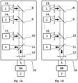
- Figs. 1A and 1B are illustrating a schematic system for rescaling a signal to remove an absorption offset from an optical measurement when detecting gas distributions and/or gas concentrations.
- the rescaling described herein is particular suitable for Tuneable Diode Laser Absorption Technology (TDLAS), such as Gas in Scattering Media Absorption Spectroscopy (GASMAS).
- TDLAS Tuneable Diode Laser Absorption Technology
- GASMAS Gas in Scattering Media Absorption Spectroscopy
- TDLAS Tuneable Diode Laser Absorption Spectroscopy
- GASMAS is the principle that the spectrally sharp gas absorption may be distinguished from a broadband absorption of liquids and solids. This results in that a small gas absorption signal (down to a fraction of the order of 1 in 10 000) may be extracted from light passing through a scattering and absorbing material despite transmitting only a minor fraction of the injected light when using GASMAS technology.
- the wavelength is tuned over a specific gas absorption line, for example, by ramping the drive current.
- the detection is made frequency-sensitively and/or phase-sensitively.
- the light such as laser light
- the light from the at least one light source 1, 2, 3 may be wavelength modulated at a selected frequency, and synchronous intensity variations may be detected when the modulation is conducted around a gas absorption wavelength.
- the intensity of the detected light may quickly change at small variations of the wavelength, as described in S. Svanberg, Gas in Scattering Media Absorption Spectroscopy - from Basic Studies to Biomedical Applications, Lasers and Photonics Reviews 7, 779 (2013 ), which is incorporated herein by reference.
- the measured intensity of light incident on a detector 7 may then be converted to a measurement of the absorption by the gas in the sample.
- the absorption of the gas may be converted to a measurement of the average distance the light travelled through the gas.
- the travel distance, or path length may be used to estimate an unknown concentration of a second gas.
- the at least one light source 1, 2, 3 is arranged in a housing 16 which may include a gas mixture. In most cases the air mixture is ambient air, but other compositions are possible.
- the housing 16 may also include beam preparation components, for collimating the beams from the light sources, combining beams from multiple light sources and/or coupling the beams into a probe 5 for transmitting the light to a measuring site at a measuring object 6A.
- the components for collimating and/or combining the beams may typically be lenses and mirrors known to the person skilled in the art.
- a first light source 1 may either be arranged to emit light along an optical axis of the combined beam or, as illustrated, a mirror 8 may be used for folding the light beam emitted from light source 1 to be transmitted along the optical axis.
- beam combiners 9, 10 may be used for combining the beams of at least a second light source 2, 3 with the beam of the first light source 1.
- the beam combiners 9, 10 may be dichroic mirrors. Collimating lenses 13, 14, 15 may be arranged in front of each light source 1, 2, 3. Alternatively, the mirrors 8, 9 and 10 may be used for collimating the beams. Alternatively, a lens system may be arranged for collimating the beams after they have been combined.
- the light is, at least partly, transmitted in an open beam path whereby the light is traveling through the gas mixture inside the housing 16. Part of the light may therefore be absorbed by the gas mixture in the housing 16 and the absorption may cause an offset in the measured absorption signal.
- the individual light beams from each light source of the at least one light source 1, 2, 3 may be collimated and then combined into a single beam.
- the single beam may therefore include light from each light source 1, 2, 3 arranged in the housing 16.
- the combined beam may be coupled to a proximal end of a measuring probe 5 for transferring the light to a measuring site at the measurement object 6B.
- the measurement object 6B may include a cavity of pores having at least one free gas.
- the combined beam may be coupled to the proximal end of the measuring probe 5 by a lens or a lens system 12.
- the measuring probe 5 may be made of a waveguide, such as optical fibre.
- the measuring probe 5 may be held against the measuring site, or arranged inside the measuring object, such as arranged inside a human for measuring the gas in a cavity.
- the waveguide or optical fibre may be arranged in a catheter or an endoscope.
- two or more light sources 1, 2, 3 are used for measuring at least one free gas.
- the wavelengths of the at least two light sources 1, 2, 3 may be adapted to match absorption peaks of at least two gases.
- the wavelength may be adapted to about 760 nm for addressing oxygen gas, and to about 820 nm or 935 nm for addressing water vapour. Other wavelengths may be used depending on the gases to be detected.
- the concentration of water vapour can be estimate based on relative humidity and a measured temperature and may therefore be used as a reference gas for obtaining an estimated path length to be used when measuring gases with an unknown concentration, for example oxygen or carbon dioxide.
- gases with an unknown concentration for example oxygen or carbon dioxide.
- other gases than water vapour may be used as a reference gas. The requirement is only that the gas concentration may be calculated without using the path length the detected light has travelled through the cavity or pores in which the gas with an unknown concentration is located.
- one light source 1, 2, 3 may be used and the path length through the cavity and pores may be estimated by other means.
- the at least one light source 1, 2, 3 may be semiconductor lasers, for example distributed feed-back lasers (DFBL), vertical cavity surface emitting lasers (VCSEL) or other types of available lasers.
- DFBL distributed feed-back lasers
- VCSEL vertical cavity surface emitting lasers
- the power of the emitted light is preferably in the range 0.1mW to 3000mW.
- the lasers may be driven by a current and temperature regulating unit included in a drive unit.
- the drive unit may be controlled by a control unit, such as a computer.
- the control unit may be used for signal processing and evaluation of the measured data. All determinations or calculations described herein may be performed by a control unit or a data processing device (not illustrated).
- control unit or a data processing device may be implemented by special-purpose software (or firmware) run on one or more general-purpose or special-purpose computing devices.
- each "element” or “means” of such a computing device refers to a conceptual equivalent of a method step; there is not always a one-to-one correspondence between elements/means and particular pieces of hardware or software routines.
- One piece of hardware sometimes comprises different means/elements.
- a processing unit serves as one element/means when executing one instruction, but serves as another element/means when executing another instruction.
- one element/means may be implemented by one instruction in some cases, but by a plurality of instructions in some other cases.
- Such a software-controlled computing device may include one or more processing units, e.g., a CPU ("Central Processing Unit"), a DSP ("Digital Signal Processor"), an ASIC ("Application-Specific Integrated Circuit”), discrete analogue and/or digital components, or some other programmable logical device, such as an FPGA ("Field Programmable Gate Array”).
- the data processing device may further include a system memory and a system bus that couples various system components including the system memory to the processing unit.
- the system bus may be any of several types of bus structures including a memory bus or memory controller, a peripheral bus, and a local bus using any of a variety of bus architectures.
- the system memory may include computer storage media in the form of volatile and/or non-volatile memory such as read only memory (ROM), random access memory (RAM) and flash memory.
- the special purpose software may be stored in the system memory, or on other removable/non-removable volatile/non-volatile computer storage media which is included in or accessible to the computing device, such as magnetic media, optical media, flash memory cards, digital tape, solid state RAM, solid state ROM, etc.
- the data processing device may include one or more communication interfaces, such as a serial interface, a parallel interface, a USB interface, a wireless interface, a network adapter, etc., as well as one or more data acquisition devices, such as an A/D converter.
- the special-purpose software may be provided to the control unit or data processing device on any suitable computer readable medium, including a record medium and a read-only memory.
- the system further includes a detector 7 for detecting light being transmitted through, or back scattered from, the measurement object 6B to be measured.
- the detector 7 may be arranged directly on the object 6B to be measure, or a waveguide, such as fibres could be used to collect the light at the object 6B to be measured and transmitting it to the detector 7.
- the detector unit 7 may include photodiodes, photomultiplier tubes, avalanche photodiodes, charge-coupled devices (CCD), or CMOS light sensitive devices.
- the detector unit 7 When measuring on tissue, for example on a gas in a cavity in a human body such as a lung, the detector unit 7 may be adapted to be positioned dermally on the subject.
- Fig 1A is illustrating a first mode, which may be an offset-adjustment mode of the system.
- the system includes a second detector 4 which is a reference detector.
- the reference detector 4 may be arranged inside the housing 16. Alternatively, the reference detector 4 may be connected directly to the housing 16 or to the housing 16 via a waveguide, such as a fibre.
- a first light signal from each of at least one light source 1, 2, or 3 located in the housing 16 is transmitted through, or back scattered, from a reference object 6A located outside of the housing 16.
- the light is detected by an external detector 7.
- the external detector 7 may be the same detector 7 as the detector used when performing the measurements on the measurement object 6B including a cavity with a gas to be measured, such as a human subject.
- the reference object 6A is preferably a gas-free medium.
- the reference object 6A may have a cavity or pores with a known gas concentration/absorption.
- the known gas concentration/absorption is preferably made of the same gases to be detected in the measurement object 6B.
- the light is transmitted from the housing 16 to the reference object 6A using the measuring probe 5 to be used for the measurements on the measurement object 6B, such as a human subject.
- a second light signal from each of the at least one light source 1, 2, 3 located in the housing 16, is measured using the reference detector 4.
- the first and second light signal may be measured simultaneously or sequentially.
- a beam sampler 11 may be used for measuring the first and second light signal.
- the first light signal may be a first portion of the combined beam and the second light signal may be a second portion of the combined beam.
- the combined light beam is split into two portions.
- a control unit may then be used for calculating a separate scaling factor related each of the at least one light source 1, 2, 3, arranged inside the housing 16, using the detected first light signal and the detected second light signal.
- the first and second light signals may be measured simultaneously or sequentially.
- Fig. 1B is illustrating a second mode, which may be measuring mode.
- the second mode may be a consecutive mode and may be performed after the first mode has been completed.
- the measurement mode may be performed first, and the offset-adjustment mode may be performed after.
- the measurement is performed on the measurement object 6B.
- a third light signal from each of the at least one light source 1, 2, 3, located in a housing 16, is measured using the external detector 7.
- the detected third light signal has been transmitted through, or back scattered, from the measurement object 6B.
- the light signal is transmitted from the housing 16 to the measurement object 6B via a measuring probe 5.
- the measuring probe 5 is the same as the probe 5 used for the measurements during the first mode, i.e., the offset-adjustment mode.
- a fourth light signal from each of the at least one light source 1, 2, 3, located in the housing 16, is measured using the reference detector 4.
- the third and fourth light signal may be measured simultaneously or sequentially.
- a fourth light signal may be measured between each measured third light signal, or after two measured third light signals, or after each third measured third light signal, or after each fourth measured third light signal etc.
- a beam sampler 11 For measuring the first and second light signals, and/or the third and fourth light signals, a beam sampler 11 may be used.
- the first light signal, and/or the third light signal may be a first portion of the combined light beam and the second light signal, and/or the fourth light signal, may be a second portion of the combined light beam.
- the calculated scaling factor, related to each of the at least one light sources may be applied to each of the detected fourth light signal, respectively.
- the resulting values related to each of the at least one light source 1, 2, 3 may be subtracted from the detected third light signal of each of the at least one light source 1, 2, 3 transmitted through, or back-scattered from, the measuring object 6B.
- the third signal of the at least one light source may then be rescaled, and the offset caused by the gas in the housing 16 may be removed to obtain a corrected light signal for each of the at least one light source 1, 2, 3 based on the third light signal obtained from performing a measurement on the measurement object 6B.
- the corrected light signal may then be used for estimating and/or calculating a gas absorption of a free gas in the cavity or pores in the measurement object 6B.
- the absorption may be used for obtaining, estimating and/or calculating a gas distribution and/or gas concentration of the gas free in the cavity or pores in the measurement object 6B.
- a path length from the at least one light source 1, 2, 3 to the reference detector 4 may differ from a path length from the at least one light source 1, 2, 3 to the external detector 7.
- an individual scaling factor may be calculated for each of the at least one light source.
- the beam sampler arrangement 11 may be a diffuser arranged in the beam path and the reference detector 4 may be arranged to directly detect a portion of the diffused light before the light is coupled to the probe 5.
- the beam from the at least on light source 1, 2, 3 may be collimated using optical components, such as a system of lenses.
- the collimated beam may have a diameter of about 1 to 4 mm or larger. In some examples, the diameter may be smaller than 1 mm depending on the detector used.
- the reference detector 4 may be arranged to directly sample a portion of this collimated beam while the signal not being detected by the reference detector 4 is coupled to the probe 5.
- a beam sampler arrangement 11 may be to arrange a beam splitter in the beam path.
- the beam splitter may direct a portion of the beam emitted from the at least one light source 1, 2, 3 to the reference detector 4 and transmit another portion to be coupled to the probe 5.
- a mirror may be arranged in the beam path, such as a dichroic mirror or a pick-off mirror.
- the mirror may direct a portion of the beam to the reference detector 4 while allowing another portion to be transmitted and coupled to the probe 5.
- a reference detector may be used for each of the light sources 1, 2, 3.
- a portion of the emitted light from each light source 1, 2, 3 may be detected by each reference detector 4 before the light from each light source 1, 2, 3 is joint into a single beam and coupled to the probe 5.
- a moving mirror such as a flipping, may be used to divert the beam between the reference detector 4 and to be coupled to the probe 5.
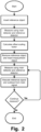
- Fig 2 is illustrating an exemplary flowchart of a method for rescaling a signal to remove an absorption offset in a light signal during optical measurements.
- the offset may be caused by the beam being transmitted as an open beam through a gas mixture, such as ambient air.
- the method may include: A first mode wherein a reference object is inserted at a distal end of an optical probe.
- the first light signal from each of the at least one light source may be transmitted as a combined beam being the light signals from each of the at least one light source combined into a single beam.
- the second light signal from each of the at least one light source located in the housing may be transmitted as a combined beam being the light signals from each of the at least one light source combined into a single beam.
- a second mode such as a consecutively performed mode, wherein the reference object is removed, and the measurement object is placed on the measurement object.
- the third light signal from each of the at least one light source located in a housing which has been transmitted through, or back scattered from, a measurement object located outside of the housing using the external detector.
- the third light signal from each of the at least one light source may be transmitted as a combined beam being the light signals from each of the at least one light source combined into a single beam.
- the fourth light signal from each of the at least one light source located in the housing may be transmitted as a combined beam being the light signals from each of the at least one light source combined into a single beam.
- the corrected light signal may then be used for obtaining the gas absorption, distribution and/or concentration in a cavity or pores of the measurement object.
Landscapes
- Health & Medical Sciences (AREA)
- Physics & Mathematics (AREA)
- Life Sciences & Earth Sciences (AREA)
- Spectroscopy & Molecular Physics (AREA)
- Pathology (AREA)
- General Health & Medical Sciences (AREA)
- Engineering & Computer Science (AREA)
- General Physics & Mathematics (AREA)
- Surgery (AREA)
- Biomedical Technology (AREA)
- Heart & Thoracic Surgery (AREA)
- Medical Informatics (AREA)
- Molecular Biology (AREA)
- Animal Behavior & Ethology (AREA)
- Public Health (AREA)
- Veterinary Medicine (AREA)
- Biophysics (AREA)
- Chemical & Material Sciences (AREA)
- Immunology (AREA)
- Biochemistry (AREA)
- Analytical Chemistry (AREA)
- Obesity (AREA)
- Physiology (AREA)
- Emergency Medicine (AREA)
- Pulmonology (AREA)
- Optics & Photonics (AREA)
- Mathematical Physics (AREA)
- Theoretical Computer Science (AREA)
- Investigating Or Analysing Materials By Optical Means (AREA)
Claims (15)
- Verfahren zur Neuskalierung eines Lichtsignals, um eine Absorptionsverschiebung aus dem Lichtsignal bei einer optischen Messung zu entfernen, wobei die Absorptionsverschiebung auf ein Gasgemisch in einem Gehäuse (16) zurückzuführen ist, durch das das Lichtsignal übertragen wurde, wobei das Verfahren Folgendes umfasst:
einen ersten Modus mit:Messung eines ersten Lichtsignals von jeder der mindestens einen Lichtquelle (1, 2, 3), die sich in dem Gehäuse befindet, wobei das erste Lichtsignal durch ein außerhalb des Gehäuses befindliches Bezugsobjekt (6A) übertragen oder von diesem zurückgestreut wurde, unter Verwendung eines externen Detektors (7);Messung eines zweiten Lichtsignals von jeder der mindestens einen Lichtquelle, die sich in dem Gehäuse befindet, unter Verwendung eines Referenzdetektors (4);Berechnen eines Skalierungsfaktors, der sich auf jede der mindestens einen Lichtquelle bezieht, unter Verwendung des erfassten ersten Lichtsignals und des erfassten zweiten Lichtsignals; undeinen zweiten Modus, z. B. einen konsekutiven zweiten Modus mit:Messung eines dritten Lichtsignals von jeder der mindestens einen Lichtquelle, die sich in dem Gehäuse befindet, wobei das dritte Lichtsignal durch ein Messobjekt (6B), das anstelle des außerhalb des Gehäuses befindlichen Bezugsobjekts (6A) eingesetzt wurde, übertragen oder von diesem zurückgestreut wurde, unter Verwendung des externen Detektors;Messung eines vierten Lichtsignals von jeder der mindestens einen Lichtquelle, die sich in dem Gehäuse befindet, unter Verwendung eines Referenzdetektors;Anwendung des Skalierungsfaktors auf jedes erfasste vierte Lichtsignal, das dann von jedem erfassten dritten Lichtsignal subtrahiert wird, das durch das Messobjekt hindurchgeht oder von diesem zurückgestreut wird. - Verfahren nach Anspruch 1 mit Übertragen des ersten Lichtsignals vom Gehäuse zum Bezugsobjekt und/oder Übertragen des dritten Lichtsignals vom Gehäuse zum Messobjekt unter Verwendung einer Fasersonde.
- Verfahren nach einem der Ansprüche 1 bis 2, wobei das Messobjekt ein Hohlraum, wie z. B. ein Lungenflügel, in einem Körper ist.
- Verfahren nach einem der Ansprüche 1 bis 3, wobei das dritte Lichtsignal zur Messung einer Gasabsorption verwendet wird.
- Verfahren nach Anspruch 4, bei dem die Gasabsorption dazu verwendet wird, eine Konzentration von freiem Gas in diesem Hohlraum zu erhalten.
- Verfahren nach einem der Ansprüche 1 bis 5, wobei das Bezugsobjekt ein gasfreies Medium ist.
- Verfahren nach einem der Ansprüche 1 bis 6, wobei der Referenzdetektor im Inneren des Gehäuses angeordnet ist.
- Verfahren nach einem der Ansprüche 1 bis 7, wobei die Weglänge von der mindestens einen Lichtquelle zu dem Referenzdetektor unterschiedlich zu der Weglänge von der mindestens einen Lichtquelle zu dem externen Detektor ist.
- Verfahren nach einem der Ansprüche 1 bis 8, wobei die Skalierungsfaktoren für jede der mindestens einen Lichtquelle separat berechnet werden.
- Verfahren nach einem der Ansprüche 1 bis 9, wobei die Messungen unter Verwendung der abstimmbaren Diodenlasertechnologie durchgeführt werden, wie sie für GASMAS verwendet wird.
- Verfahren nach einem der Ansprüche 1 bis 10, wobei das erste Signal und das zweite Signal gleichzeitig während des ersten Modus gemessen werden und/oder wobei das dritte Signal und das vierte Signal gleichzeitig während des zweiten Modus gemessen werden.
- Medizinische Vorrichtung zur Durchführung einer optischen Messung, wobei die Vorrichtung Folgendes umfasst: ein Gehäuse (16), das ein Gasgemisch enthält;mindestens eine Lichtquelle (1, 2, 3), die in dem Gehäuse angeordnet ist und so konfiguriert ist, dass sie ein Lichtsignal überträgt, das jeder Lichtquelle der mindestens einen Lichtquelle entspricht,einen externen Detektor (7) und einen Referenzdetektor (4)eine optische Vorrichtung (11), die so konfiguriert ist, dass sie das Lichtsignal aus dem Gehäuse zu dem externen Detektor und das Lichtsignal zu dem Referenzdetektor leitet;eine Steuereinheit, konfiguriert für den Betrieb in:einem ersten Modus, in dem das Lichtsignal, das ein erstes Lichtsignal ist, das durch ein Referenzobjekt (6A) hindurchgeht oder von diesem zurückgestreut wird, unter Verwendung des externen Detektors aufgezeichnet wird, und in dem das Lichtsignal, das ein zweites Lichtsignal ist, unter Verwendung des Referenzdetektors aufgezeichnet wird, wobei ein Skalierungsfaktor unter Verwendung des erfassten ersten Lichtsignals und des erfassten zweiten Lichtsignals berechnet wird; undeinem zweiten Modus, in dem das Lichtsignal, das ein drittes Lichtsignal ist, das durch ein anstelle des Referenzobjekts (6A) eingefügtes Messobjekt (6B) hindurchgeht oder von diesem zurückgestreut wird, unter Verwendung des externen Detektors aufgezeichnet wird, und in dem das Lichtsignal, das ein viertes Lichtsignal ist, unter Verwendung des Referenzdetektors aufgezeichnet wird, wobei der Skalierungsfaktor auf das erfasste vierte Lichtsignal angewendet und von dem erfassten dritten Lichtsignal subtrahiert wird, um ein korrigiertes Lichtsignal mit einer verringerten Absorptionsverschiebung zu erhalten.
- Vorrichtung nach Anspruch 12, wobei der Referenzdetektor in dem Gehäuse angebracht ist.
- Vorrichtung nach einem der Ansprüche 12 oder 13, wobei es sich bei der optischen Anordnung um einen Strahlsammler, wie z. B. einen Strahlenteiler, oder einen Ablenkspiegel handelt.
- Vorrichtung nach einem der Ansprüche 12 bis 14, wobei das erste Lichtsignal ein erster Teil des Lichtsignals ist und das zweite Lichtsignal ein zweiter Teil des Lichtsignals ist, das während des ersten Modus ausgesendet wird, und/oder wobei das dritte Lichtsignal ein dritter Teil des Lichtsignals ist und das vierte Lichtsignal ein vierter Teil des Lichtsignals ist, das während des zweiten Modus ausgesendet wird.
Applications Claiming Priority (2)
| Application Number | Priority Date | Filing Date | Title |
|---|---|---|---|
| SE2150086A SE544842C2 (en) | 2021-01-27 | 2021-01-27 | A method and device for rescaling a signal to remove an absorption offset from an optical measurement |
| PCT/EP2022/051962 WO2022162098A1 (en) | 2021-01-27 | 2022-01-27 | A method and device for offset compensation |
Publications (3)
| Publication Number | Publication Date |
|---|---|
| EP4284232A1 EP4284232A1 (de) | 2023-12-06 |
| EP4284232B1 true EP4284232B1 (de) | 2024-09-25 |
| EP4284232C0 EP4284232C0 (de) | 2024-09-25 |
Family
ID=80168063
Family Applications (1)
| Application Number | Title | Priority Date | Filing Date |
|---|---|---|---|
| EP22702268.8A Active EP4284232B1 (de) | 2021-01-27 | 2022-01-27 | Verfahren und vorrichtung zur offset-kompensation |
Country Status (5)
| Country | Link |
|---|---|
| US (1) | US12440107B2 (de) |
| EP (1) | EP4284232B1 (de) |
| CN (1) | CN116761545B (de) |
| SE (1) | SE544842C2 (de) |
| WO (1) | WO2022162098A1 (de) |
Families Citing this family (1)
| Publication number | Priority date | Publication date | Assignee | Title |
|---|---|---|---|---|
| WO2025252733A1 (en) * | 2024-06-03 | 2025-12-11 | Neola Medical AB | A method and device for improving responsiveness in spectroscopy applications |
Family Cites Families (18)
| Publication number | Priority date | Publication date | Assignee | Title |
|---|---|---|---|---|
| US6107631A (en) * | 1998-03-13 | 2000-08-22 | Alliedsignal Inc. | Self-calibration approach for tunable laser spectral absorption sensors |
| SE521061C2 (sv) * | 1998-12-01 | 2003-09-30 | Tetra Laval Holdings & Finance | Förfarande och anordning för koncentrationsmätning av ett ämne i ett vätske-eller gasformigt steriliseringsmedium |
| DK1549932T3 (da) * | 2003-09-12 | 2006-06-06 | Ir Microsystems S A | Fremgangsmåde og apparat til gasdetektering |
| SE530817C2 (sv) * | 2005-04-18 | 2008-09-16 | Gasporox Ab | Anordning för mätning av en fri gas i människans hålrum |
| JP2009236499A (ja) * | 2008-03-25 | 2009-10-15 | Keyence Corp | 接触式変位計 |
| US9360415B2 (en) * | 2010-10-21 | 2016-06-07 | Spectrasensors, Inc. | Dynamic reconstruction of a calibration state of an absorption spectrometer |
| US9772226B2 (en) * | 2011-07-11 | 2017-09-26 | Verity Instruments, Inc. | Referenced and stabilized optical measurement system |
| US8730466B2 (en) * | 2011-07-14 | 2014-05-20 | Thermo Electron Scientific Instruments Llc | Optical spectrometer with underfilled fiber optic sample interface |
| US8896835B2 (en) * | 2011-12-27 | 2014-11-25 | Horiba, Ltd. | Gas measurement apparatus and the setting method of width of wavelength modulation in gas measurement apparatus |
| JP5927561B2 (ja) * | 2012-05-31 | 2016-06-01 | パナソニックIpマネジメント株式会社 | 光ディスク情報装置及び情報処理装置 |
| US20140022381A1 (en) * | 2012-07-17 | 2014-01-23 | Tetracam, Inc. | Radiometric multi-spectral or hyperspectral camera array using matched area sensors and a calibrated ambient light collection device |
| US9335257B2 (en) * | 2013-06-20 | 2016-05-10 | Rosemount Analytical Inc. | Tunable diode laser absorption spectroscopy with water vapor determination |
| CN103499545B (zh) * | 2013-10-14 | 2015-09-09 | 北京信息科技大学 | 采用气体参考腔反馈补偿的半导体激光器气体检测系统 |
| SE1500335A1 (sv) | 2015-08-17 | 2017-02-18 | Utrustning och metod för intern laserbelysning för medicinskgasanalys | |
| CN113766870B (zh) * | 2019-04-26 | 2025-02-25 | 尼奥拉医疗公司 | 一种用于监测受试者肺系统的装置 |
| US11747272B2 (en) * | 2019-06-10 | 2023-09-05 | Analog Devices, Inc. | Gas detection using differential path length measurement |
| CN110261328B (zh) * | 2019-07-19 | 2022-04-08 | 宁波海尔欣光电科技有限公司 | 校准激光波长的方法及装置、气体浓度分析仪 |
| CN110927100B (zh) * | 2019-11-26 | 2022-11-29 | 宁波海尔欣光电科技有限公司 | 用于测量气体通量的系统和测量气体通量的方法 |
-
2021
- 2021-01-27 SE SE2150086A patent/SE544842C2/en unknown
-
2022
- 2022-01-27 WO PCT/EP2022/051962 patent/WO2022162098A1/en not_active Ceased
- 2022-01-27 EP EP22702268.8A patent/EP4284232B1/de active Active
- 2022-01-27 CN CN202280011389.2A patent/CN116761545B/zh active Active
- 2022-01-27 US US18/262,550 patent/US12440107B2/en active Active
Also Published As
| Publication number | Publication date |
|---|---|
| WO2022162098A1 (en) | 2022-08-04 |
| US12440107B2 (en) | 2025-10-14 |
| EP4284232A1 (de) | 2023-12-06 |
| CN116761545B (zh) | 2025-11-07 |
| SE2150086A1 (en) | 2022-07-28 |
| EP4284232C0 (de) | 2024-09-25 |
| CN116761545A (zh) | 2023-09-15 |
| SE544842C2 (en) | 2022-12-13 |
| US20240293030A1 (en) | 2024-09-05 |
Similar Documents
| Publication | Publication Date | Title |
|---|---|---|
| US20100041969A1 (en) | Measuring device and method for optically determining the concentration of blood sugar and/or lactate in biological systems | |
| JP6786752B2 (ja) | フォトサーマル干渉装置および方法 | |
| US10241039B2 (en) | Spectroscopic analyser | |
| US6377840B1 (en) | Signal acquisition and processing system for reduced output signal drift in a spectrophotometric instrument | |
| CN204515135U (zh) | 一种探测大气二氧化碳浓度的激光雷达系统 | |
| CN104822841B (zh) | 检测细菌感染的方法 | |
| US9829479B2 (en) | Photoacoustic imaging device and oxygen saturation measurement method | |
| CN204556499U (zh) | 调谐二极管吸收光谱的多通道高速数据采集和处理系统 | |
| Azhar et al. | A widely tunable, near-infrared laser-based trace gas sensor for hydrogen cyanide (HCN) detection in exhaled breath | |
| WO2011117572A1 (en) | Analysis of breath | |
| CN1314368C (zh) | 测量待测物中成分浓度的方法和设备 | |
| CN111208082A (zh) | 基于中红外吸收光谱测量的气体检测系统 | |
| EP4284232B1 (de) | Verfahren und vorrichtung zur offset-kompensation | |
| US20250383234A1 (en) | No-ref-signal slope spectroscopic measurement | |
| JP6000957B2 (ja) | 光学測定装置および校正方法 | |
| Lacerenza et al. | Functional monitoring of lung tissue using a hybrid hyperspectral Time-Resolved GASMAS system: a systematic study on ex vivo sample. | |
| JP3336261B2 (ja) | 半導体レーザを用いた同位体の分光分析方法 | |
| EP3992614B1 (de) | Analysevorrichtung | |
| WO2025252733A1 (en) | A method and device for improving responsiveness in spectroscopy applications | |
| RU2829452C1 (ru) | Способ лазерного зондирования парниковых газов в атмосфере | |
| JP2001013070A (ja) | 果実成分非破壊測定器 | |
| Sowoidnich et al. | Mobile Raman sensors for on-site measurements to address agri-photonic and life science applications | |
| Widiatmono et al. | Sub ppb CO gas measurement using a non invasive QCL laser absorption spectrometer technique | |
| EP1183522A1 (de) | Vorrichtung zur erfassung und verarbeitung des signals eines photospektrometers zwecks verringerung der drift des ausgangssignals | |
| Weibring et al. | Ultra-high precision trace gas detection using difference-frequency generation sources |
Legal Events
| Date | Code | Title | Description |
|---|---|---|---|
| STAA | Information on the status of an ep patent application or granted ep patent |
Free format text: STATUS: UNKNOWN |
|
| STAA | Information on the status of an ep patent application or granted ep patent |
Free format text: STATUS: THE INTERNATIONAL PUBLICATION HAS BEEN MADE |
|
| PUAI | Public reference made under article 153(3) epc to a published international application that has entered the european phase |
Free format text: ORIGINAL CODE: 0009012 |
|
| STAA | Information on the status of an ep patent application or granted ep patent |
Free format text: STATUS: REQUEST FOR EXAMINATION WAS MADE |
|
| 17P | Request for examination filed |
Effective date: 20230824 |
|
| AK | Designated contracting states |
Kind code of ref document: A1 Designated state(s): AL AT BE BG CH CY CZ DE DK EE ES FI FR GB GR HR HU IE IS IT LI LT LU LV MC MK MT NL NO PL PT RO RS SE SI SK SM TR |
|
| DAV | Request for validation of the european patent (deleted) | ||
| DAX | Request for extension of the european patent (deleted) | ||
| GRAP | Despatch of communication of intention to grant a patent |
Free format text: ORIGINAL CODE: EPIDOSNIGR1 |
|
| STAA | Information on the status of an ep patent application or granted ep patent |
Free format text: STATUS: GRANT OF PATENT IS INTENDED |
|
| INTG | Intention to grant announced |
Effective date: 20240612 |
|
| GRAS | Grant fee paid |
Free format text: ORIGINAL CODE: EPIDOSNIGR3 |
|
| GRAA | (expected) grant |
Free format text: ORIGINAL CODE: 0009210 |
|
| STAA | Information on the status of an ep patent application or granted ep patent |
Free format text: STATUS: THE PATENT HAS BEEN GRANTED |
|
| AK | Designated contracting states |
Kind code of ref document: B1 Designated state(s): AL AT BE BG CH CY CZ DE DK EE ES FI FR GB GR HR HU IE IS IT LI LT LU LV MC MK MT NL NO PL PT RO RS SE SI SK SM TR |
|
| REG | Reference to a national code |
Ref country code: GB Ref legal event code: FG4D |
|
| REG | Reference to a national code |
Ref country code: CH Ref legal event code: EP |
|
| REG | Reference to a national code |
Ref country code: DE Ref legal event code: R096 Ref document number: 602022006398 Country of ref document: DE |
|
| REG | Reference to a national code |
Ref country code: IE Ref legal event code: FG4D |
|
| U01 | Request for unitary effect filed |
Effective date: 20240926 |
|
| U07 | Unitary effect registered |
Designated state(s): AT BE BG DE DK EE FI FR IT LT LU LV MT NL PT RO SE SI Effective date: 20241007 |
|
| PG25 | Lapsed in a contracting state [announced via postgrant information from national office to epo] |
Ref country code: NO Free format text: LAPSE BECAUSE OF FAILURE TO SUBMIT A TRANSLATION OF THE DESCRIPTION OR TO PAY THE FEE WITHIN THE PRESCRIBED TIME-LIMIT Effective date: 20241225 |
|
| PG25 | Lapsed in a contracting state [announced via postgrant information from national office to epo] |
Ref country code: GR Free format text: LAPSE BECAUSE OF FAILURE TO SUBMIT A TRANSLATION OF THE DESCRIPTION OR TO PAY THE FEE WITHIN THE PRESCRIBED TIME-LIMIT Effective date: 20241226 |
|
| PG25 | Lapsed in a contracting state [announced via postgrant information from national office to epo] |
Ref country code: RS Free format text: LAPSE BECAUSE OF FAILURE TO SUBMIT A TRANSLATION OF THE DESCRIPTION OR TO PAY THE FEE WITHIN THE PRESCRIBED TIME-LIMIT Effective date: 20241225 |
|
| PG25 | Lapsed in a contracting state [announced via postgrant information from national office to epo] |
Ref country code: RS Free format text: LAPSE BECAUSE OF FAILURE TO SUBMIT A TRANSLATION OF THE DESCRIPTION OR TO PAY THE FEE WITHIN THE PRESCRIBED TIME-LIMIT Effective date: 20241225 Ref country code: NO Free format text: LAPSE BECAUSE OF FAILURE TO SUBMIT A TRANSLATION OF THE DESCRIPTION OR TO PAY THE FEE WITHIN THE PRESCRIBED TIME-LIMIT Effective date: 20241225 Ref country code: GR Free format text: LAPSE BECAUSE OF FAILURE TO SUBMIT A TRANSLATION OF THE DESCRIPTION OR TO PAY THE FEE WITHIN THE PRESCRIBED TIME-LIMIT Effective date: 20241226 |
|
| U20 | Renewal fee for the european patent with unitary effect paid |
Year of fee payment: 4 Effective date: 20250128 |
|
| PG25 | Lapsed in a contracting state [announced via postgrant information from national office to epo] |
Ref country code: IS Free format text: LAPSE BECAUSE OF FAILURE TO SUBMIT A TRANSLATION OF THE DESCRIPTION OR TO PAY THE FEE WITHIN THE PRESCRIBED TIME-LIMIT Effective date: 20250125 |
|
| PG25 | Lapsed in a contracting state [announced via postgrant information from national office to epo] |
Ref country code: SM Free format text: LAPSE BECAUSE OF FAILURE TO SUBMIT A TRANSLATION OF THE DESCRIPTION OR TO PAY THE FEE WITHIN THE PRESCRIBED TIME-LIMIT Effective date: 20240925 |
|
| PG25 | Lapsed in a contracting state [announced via postgrant information from national office to epo] |
Ref country code: ES Free format text: LAPSE BECAUSE OF FAILURE TO SUBMIT A TRANSLATION OF THE DESCRIPTION OR TO PAY THE FEE WITHIN THE PRESCRIBED TIME-LIMIT Effective date: 20240925 |
|
| PG25 | Lapsed in a contracting state [announced via postgrant information from national office to epo] |
Ref country code: CZ Free format text: LAPSE BECAUSE OF FAILURE TO SUBMIT A TRANSLATION OF THE DESCRIPTION OR TO PAY THE FEE WITHIN THE PRESCRIBED TIME-LIMIT Effective date: 20240925 Ref country code: PL Free format text: LAPSE BECAUSE OF FAILURE TO SUBMIT A TRANSLATION OF THE DESCRIPTION OR TO PAY THE FEE WITHIN THE PRESCRIBED TIME-LIMIT Effective date: 20240925 |
|
| PG25 | Lapsed in a contracting state [announced via postgrant information from national office to epo] |
Ref country code: SK Free format text: LAPSE BECAUSE OF FAILURE TO SUBMIT A TRANSLATION OF THE DESCRIPTION OR TO PAY THE FEE WITHIN THE PRESCRIBED TIME-LIMIT Effective date: 20240925 |
|
| PLBE | No opposition filed within time limit |
Free format text: ORIGINAL CODE: 0009261 |
|
| STAA | Information on the status of an ep patent application or granted ep patent |
Free format text: STATUS: NO OPPOSITION FILED WITHIN TIME LIMIT |
|
| REG | Reference to a national code |
Ref country code: CH Ref legal event code: PL |
|
| 26N | No opposition filed |
Effective date: 20250626 |
|
| PG25 | Lapsed in a contracting state [announced via postgrant information from national office to epo] |
Ref country code: MC Free format text: LAPSE BECAUSE OF FAILURE TO SUBMIT A TRANSLATION OF THE DESCRIPTION OR TO PAY THE FEE WITHIN THE PRESCRIBED TIME-LIMIT Effective date: 20240925 |
|
| PG25 | Lapsed in a contracting state [announced via postgrant information from national office to epo] |
Ref country code: CH Free format text: LAPSE BECAUSE OF NON-PAYMENT OF DUE FEES Effective date: 20250131 |