EP4284230B1 - Vorrichtungen und systeme zur überwachung und behandlung von katarakt - Google Patents
Vorrichtungen und systeme zur überwachung und behandlung von katarakt Download PDFInfo
- Publication number
- EP4284230B1 EP4284230B1 EP21731407.9A EP21731407A EP4284230B1 EP 4284230 B1 EP4284230 B1 EP 4284230B1 EP 21731407 A EP21731407 A EP 21731407A EP 4284230 B1 EP4284230 B1 EP 4284230B1
- Authority
- EP
- European Patent Office
- Prior art keywords
- light
- cataracts
- treating
- monitoring
- light source
- Prior art date
- Legal status (The legal status is an assumption and is not a legal conclusion. Google has not performed a legal analysis and makes no representation as to the accuracy of the status listed.)
- Active
Links
Images


Classifications
-
- A—HUMAN NECESSITIES
- A61—MEDICAL OR VETERINARY SCIENCE; HYGIENE
- A61B—DIAGNOSIS; SURGERY; IDENTIFICATION
- A61B3/00—Apparatus for testing the eyes; Instruments for examining the eyes
- A61B3/10—Objective types, i.e. instruments for examining the eyes independent of the patients' perceptions or reactions
- A61B3/13—Ophthalmic microscopes
-
- A—HUMAN NECESSITIES
- A61—MEDICAL OR VETERINARY SCIENCE; HYGIENE
- A61B—DIAGNOSIS; SURGERY; IDENTIFICATION
- A61B3/00—Apparatus for testing the eyes; Instruments for examining the eyes
- A61B3/0008—Apparatus for testing the eyes; Instruments for examining the eyes provided with illuminating means
-
- A—HUMAN NECESSITIES
- A61—MEDICAL OR VETERINARY SCIENCE; HYGIENE
- A61B—DIAGNOSIS; SURGERY; IDENTIFICATION
- A61B3/00—Apparatus for testing the eyes; Instruments for examining the eyes
- A61B3/10—Objective types, i.e. instruments for examining the eyes independent of the patients' perceptions or reactions
- A61B3/117—Objective types, i.e. instruments for examining the eyes independent of the patients' perceptions or reactions for examining the anterior chamber or the anterior chamber angle, e.g. gonioscopes
- A61B3/1173—Objective types, i.e. instruments for examining the eyes independent of the patients' perceptions or reactions for examining the anterior chamber or the anterior chamber angle, e.g. gonioscopes for examining the eye lens
- A61B3/1176—Objective types, i.e. instruments for examining the eyes independent of the patients' perceptions or reactions for examining the anterior chamber or the anterior chamber angle, e.g. gonioscopes for examining the eye lens for determining lens opacity, e.g. cataract
-
- A—HUMAN NECESSITIES
- A61—MEDICAL OR VETERINARY SCIENCE; HYGIENE
- A61B—DIAGNOSIS; SURGERY; IDENTIFICATION
- A61B3/00—Apparatus for testing the eyes; Instruments for examining the eyes
- A61B3/10—Objective types, i.e. instruments for examining the eyes independent of the patients' perceptions or reactions
- A61B3/13—Ophthalmic microscopes
- A61B3/135—Slit-lamp microscopes
-
- A—HUMAN NECESSITIES
- A61—MEDICAL OR VETERINARY SCIENCE; HYGIENE
- A61F—FILTERS IMPLANTABLE INTO BLOOD VESSELS; PROSTHESES; DEVICES PROVIDING PATENCY TO, OR PREVENTING COLLAPSING OF, TUBULAR STRUCTURES OF THE BODY, e.g. STENTS; ORTHOPAEDIC, NURSING OR CONTRACEPTIVE DEVICES; FOMENTATION; TREATMENT OR PROTECTION OF EYES OR EARS; BANDAGES, DRESSINGS OR ABSORBENT PADS; FIRST-AID KITS
- A61F9/00—Methods or devices for treatment of the eyes; Devices for putting in contact-lenses; Devices to correct squinting; Apparatus to guide the blind; Protective devices for the eyes, carried on the body or in the hand
- A61F9/007—Methods or devices for eye surgery
- A61F9/0079—Methods or devices for eye surgery using non-laser electromagnetic radiation, e.g. non-coherent light or microwaves
-
- A—HUMAN NECESSITIES
- A61—MEDICAL OR VETERINARY SCIENCE; HYGIENE
- A61N—ELECTROTHERAPY; MAGNETOTHERAPY; RADIATION THERAPY; ULTRASOUND THERAPY
- A61N5/00—Radiation therapy
- A61N5/06—Radiation therapy using light
- A61N5/0613—Apparatus adapted for a specific treatment
-
- A—HUMAN NECESSITIES
- A61—MEDICAL OR VETERINARY SCIENCE; HYGIENE
- A61B—DIAGNOSIS; SURGERY; IDENTIFICATION
- A61B2562/00—Details of sensors; Constructional details of sensor housings or probes; Accessories for sensors
- A61B2562/04—Arrangements of multiple sensors of the same type
- A61B2562/046—Arrangements of multiple sensors of the same type in a matrix array
-
- A—HUMAN NECESSITIES
- A61—MEDICAL OR VETERINARY SCIENCE; HYGIENE
- A61N—ELECTROTHERAPY; MAGNETOTHERAPY; RADIATION THERAPY; ULTRASOUND THERAPY
- A61N5/00—Radiation therapy
- A61N5/06—Radiation therapy using light
- A61N2005/0626—Monitoring, verifying, controlling systems and methods
-
- A—HUMAN NECESSITIES
- A61—MEDICAL OR VETERINARY SCIENCE; HYGIENE
- A61N—ELECTROTHERAPY; MAGNETOTHERAPY; RADIATION THERAPY; ULTRASOUND THERAPY
- A61N5/00—Radiation therapy
- A61N5/06—Radiation therapy using light
- A61N2005/0626—Monitoring, verifying, controlling systems and methods
- A61N2005/0627—Dose monitoring systems and methods
-
- A—HUMAN NECESSITIES
- A61—MEDICAL OR VETERINARY SCIENCE; HYGIENE
- A61N—ELECTROTHERAPY; MAGNETOTHERAPY; RADIATION THERAPY; ULTRASOUND THERAPY
- A61N5/00—Radiation therapy
- A61N5/06—Radiation therapy using light
- A61N2005/0632—Constructional aspects of the apparatus
- A61N2005/0633—Arrangements for lifting or hinging the frame which supports the light sources
-
- A—HUMAN NECESSITIES
- A61—MEDICAL OR VETERINARY SCIENCE; HYGIENE
- A61N—ELECTROTHERAPY; MAGNETOTHERAPY; RADIATION THERAPY; ULTRASOUND THERAPY
- A61N5/00—Radiation therapy
- A61N5/06—Radiation therapy using light
- A61N2005/0635—Radiation therapy using light characterised by the body area to be irradiated
- A61N2005/0643—Applicators, probes irradiating specific body areas in close proximity
- A61N2005/0645—Applicators worn by the patient
- A61N2005/0647—Applicators worn by the patient the applicator adapted to be worn on the head
- A61N2005/0648—Applicators worn by the patient the applicator adapted to be worn on the head the light being directed to the eyes
-
- A—HUMAN NECESSITIES
- A61—MEDICAL OR VETERINARY SCIENCE; HYGIENE
- A61N—ELECTROTHERAPY; MAGNETOTHERAPY; RADIATION THERAPY; ULTRASOUND THERAPY
- A61N5/00—Radiation therapy
- A61N5/06—Radiation therapy using light
- A61N2005/065—Light sources therefor
- A61N2005/0651—Diodes
-
- A—HUMAN NECESSITIES
- A61—MEDICAL OR VETERINARY SCIENCE; HYGIENE
- A61N—ELECTROTHERAPY; MAGNETOTHERAPY; RADIATION THERAPY; ULTRASOUND THERAPY
- A61N5/00—Radiation therapy
- A61N5/06—Radiation therapy using light
- A61N2005/0658—Radiation therapy using light characterised by the wavelength of light used
- A61N2005/0662—Visible light
- A61N2005/0663—Coloured light
-
- A—HUMAN NECESSITIES
- A61—MEDICAL OR VETERINARY SCIENCE; HYGIENE
- A61N—ELECTROTHERAPY; MAGNETOTHERAPY; RADIATION THERAPY; ULTRASOUND THERAPY
- A61N5/00—Radiation therapy
- A61N5/06—Radiation therapy using light
- A61N2005/0664—Details
- A61N2005/0665—Reflectors
-
- A—HUMAN NECESSITIES
- A61—MEDICAL OR VETERINARY SCIENCE; HYGIENE
- A61N—ELECTROTHERAPY; MAGNETOTHERAPY; RADIATION THERAPY; ULTRASOUND THERAPY
- A61N5/00—Radiation therapy
- A61N5/06—Radiation therapy using light
- A61N2005/0664—Details
- A61N2005/0665—Reflectors
- A61N2005/0666—Reflectors for redirecting light to the treatment area
-
- A—HUMAN NECESSITIES
- A61—MEDICAL OR VETERINARY SCIENCE; HYGIENE
- A61N—ELECTROTHERAPY; MAGNETOTHERAPY; RADIATION THERAPY; ULTRASOUND THERAPY
- A61N5/00—Radiation therapy
- A61N5/06—Radiation therapy using light
- A61N2005/0664—Details
- A61N2005/0667—Filters
-
- G—PHYSICS
- G01—MEASURING; TESTING
- G01N—INVESTIGATING OR ANALYSING MATERIALS BY DETERMINING THEIR CHEMICAL OR PHYSICAL PROPERTIES
- G01N21/00—Investigating or analysing materials by the use of optical means, i.e. using sub-millimetre waves, infrared, visible or ultraviolet light
- G01N21/62—Systems in which the material investigated is excited whereby it emits light or causes a change in wavelength of the incident light
- G01N21/63—Systems in which the material investigated is excited whereby it emits light or causes a change in wavelength of the incident light optically excited
- G01N21/64—Fluorescence; Phosphorescence
- G01N21/6486—Measuring fluorescence of biological material, e.g. DNA, RNA, cells
Definitions
- This invention relates generally to the field of non-invasive cataract treatments, in particular, to cataract treatments using treating light of selected wavelengths. More particularly, the invention relates to an apparatus for monitoring and treating cataracts using a monitoring light source and a treating light source. Furthermore, the invention relates to systems for use with and/or within an apparatus for monitoring and treating cataracts.
- a cataract is an opacification (a clouding) of the crystalline lens of the eye due to metabolic changes of the crystalline lens fibres over time.
- the clouding may develop in the crystalline lens of the eye or in its envelope and it varies in degree from slight to complete opacity and obstructs the passage of light.
- the yellow coloration of the lens accompanying the cataract is believed to be caused by the formation of covalent cross-links and aggregation of degraded proteins in the lens.
- Covalent cross-links and other types of degradation disrupt the optical and mechanical properties of the lens.
- the cross-links may be Sulphur bridges occurring between and/or within the proteins of the lens.
- the fluorescence of cyclic molecular components of the cross-links is early evidence of this process.
- a cataract manifests itself as a protein conformational disease characterised by accumulation of light absorbing, fluorescent and scattering protein aggregates.
- a cataract causes impairment or loss of vision. Cataracts often develop slowly and can affect one or both eyes. Symptoms may include faded colours, blurry or double vision, halos around light, trouble with bright lights, and trouble seeing at night. This may result in trouble driving, reading or recognising faces.
- Cataract surgery also called lens replacement surgery, is the removal of the natural lens of the eye that has developed an opacification and its replacement with an artificial lens (i.e., an intraocular lens).
- the artificial lens is positioned in the same place as the natural lens, thus it remains a permanent part of the eye.
- cataract surgery is the only effective treatment. Cataract surgery is generally safe, but it carries a risk of infection and bleeding. Furthermore, serious complications of cataract surgery include retinal detachment and endophthalmitis. In both cases, patients notice a sudden decrease in vision. In endophthalmitis, patients often describe pain. Retinal detachment frequently presents with unilateral visual field defects, blurring of vision, flashes of light or floating spots.
- cataract surgery is the only effective treatment option, it remains unavailable in sufficient quantity for the vast majority of the world population living in areas without access to specialised health care. Therefore, reducing vision impairment or blindness due to cataracts requires solutions that can be applied outside operating theatres.
- US2011202114A1 discloses a light-based non-invasive cataract treatment method which is said to avoid or postpone the need for cataract surgery by ten to possibly thirty years.
- the method is based on a non-invasive light therapy where the age-related protein changes of the cataractic lens are reversed by radiation with laser light.
- Human donor lenses were shown to be treated (by photo-bleaching) with an 800 nm infra-red femtosecond pulsed laser in a treatment zone measuring 1x1x0.52 mm. After laser treatment, the age-induced yellow discoloration of the cataractic lens was markedly reduced and the transmission of light was increased, corresponding to an optical rejuvenation of 3 to 7 years.
- the drawback of the light-based non-invasive cataract treatment method disclosed in US2011202114A1 is that femtosecond pulsed lasers increase the complexity and the risk factor of the light-treatment apparatus, thus making the apparatus costly to maintain and hence more costs to doctors and hospital management. Also, the method only appears to delay the onset of cataracts, rather than treat them, and the treated volume is very small.
- Other cataract treatment systems are disclosed in US 2018/353769 A1 , US 9220403 A2 or US 2014/104576 A1 , for example.
- a light-based cataract treatment apparatus which is safe to use and not expensive (i.e., an apparatus which is reasonably priced and which can be safely used in a main-stream opticians shop), cures cataracts (rather than delaying the need for cataract surgery) and is able to expose a larger volume of the eye's lens to the treating light (i.e., an area as large as the area covered by a standard slit-lamp microscope routinely used in main-stream opticians shops).
- Such cataract treatment apparatus retains the eye's natural lens, avoids the need for invasive surgery and can be deployed in the community, improving availability and accessibility to cataract monitoring and treatment.
- an apparatus able to monitor and treat cataracts using monitoring and treating light sources.
- the monitoring and treating can be performed sequentially or simultaneously.
- systems for use with and/or within an apparatus for monitoring and treating cataracts Such systems would be ones whereby the apparatus for monitoring and treating cataracts can become an attachment to existing ophthalmic instruments (e.g. a slit-lamp microscope), rather than a stand-alone apparatus.
- Other systems would be ones which can be integrated within the apparatus for monitoring and treating cataracts to enable accurate selection of fluorescence wavelengths emitted by cataracts during monitoring and/or treatment.
- an object of the present invention to provide an apparatus for monitoring and treating cataracts, the apparatus having a defined focus on the monitoring and the treatment of cataracts using light sources, whereby the monitoring light, the treating light and the excited fluorescence light are reflected along a common optical axis between the eye and a device for detecting fluorescence emitted by monitored and/or treated cataracts.
- a wavelength selection system may be incorporated within the apparatus for monitoring and treating cataracts to enable the apparatus to accurately measure the fluorescence of two fluorescent bands characteristic of cataracts emission. Such a system would allow the apparatus to have a good emission light to noise ratio from the cataract fluorescence.
- An apparatus control system comprising an electronic device may be used with the apparatus for monitoring and treating cataracts to enable, for example, the selection of an operating mode of the apparatus.
- the operating mode of the apparatus may be selected from (i) a monitoring mode when the electronic device manages and controls the power supply and the exposure time of a monitoring light source or (ii) a treatment mode when the electronic device manages and controls the power supply and the exposure time of a treating light source.
- an apparatus for monitoring and treating cataracts comprising: a monitoring light source configured to monitor cataracts by emitting monitoring light in the wavelength range of 350 to 410 nm to excite fluorescence light in the cataracts, a treating light source configured to treat cataracts by emitting treating light in the wavelength range of 400 to 570 nm to irradiate the cataracts, a wavelength selection system configured to monitor cataracts by selecting wavelengths of the excited fluorescence light in the cataracts and a dichroic beam splitter configured to reflect the monitoring light and the treating light towards the cataracts and the excited fluorescence light in the cataracts towards the wavelength selection system, wherein the monitoring light, the treating light and the excited fluorescence light are reflected by the dichroic beam splitter along a common optical axis and wherein the dichroic beam splitter is arranged at 45 degrees to the common optical axis to transmit wavelengths longer than wavelengths of the monitoring light, the treating light and the excited fluorescence light towards a user
- the advantage of having a dichroic beam splitter arranged at 45 degrees to the common optical axis is that the apparatus for monitoring and treating cataracts can become an attachment to existing ophthalmic instruments (e.g. a slit-lamp microscope, such as a Keeler slip lamp https://www.keeler.co.uk/products/slit-lamps.html ).
- the dichroic beam splitter is thus allowing long wavelength visible light to pass through to the slit-lamp microscope so that a visual (or camera) check on the positioning of the patient's eye can be maintained by the operator of the apparatus.
- This configuration in turn enables the use of a computerised tracking system using the image captured by the camera built into the slit- lamp microscope. The tracking system can alert the operator when the patient's eye moves out of position, thus allowing better control of the treated area and the actual treatment dose provided to a patient's eye.
- the dichroic beam splitter ensures that the monitoring light, the treating light and the excited fluorescence light are reflected along a common optical axis, thus enabling the apparatus to simultaneously monitor and treat cataracts and also minimise optical loses.
- the monitoring light source may comprise a non-lasing LED light source operable to emit light in the wavelength range of 350 to 410 nm, preferably in the wavelength range of 360 to 370 nm and more preferably at 365 nm to excite fluorescence light in the cataracts.
- a 365 nm monitoring (or excitation) light allows adequate penetration through the cornea into the eye and transmission of the resulting fluorescence emission spectra out of the eye. Wavelengths down to about 350 nm would also produce cataract fluorescence spectra, but would require higher excitation powers. Excitation wavelengths up to about 410 nm would provide better penetration of the cornea but reduce the information from the resulting fluorescence spectra.
- the treating light source may comprise a non-lasing LED light source operable to emit light in the wavelength range of 400 to 570 nm, preferably in the wavelength range of 410 to 420 nm and more preferably at 415 nm to irradiate the cataracts.
- a 415 nm treating light makes the cataract irradiation a truly non-invasive in-vivo treatment since it allows the treating light to be focused on the lens to protect the retina.
- the wavelength selection system may comprise any one or a combination of any one of a linear variable interference filter, a diffraction grating and a refractive prism.
- the linear variable interference filter may comprise a tuneable bandpass interference filter operable in the wavelength range of 320 to 560 nm.
- the advantage of the chosen bandwidth is that the bandpass interference filter allows measuring the natural broadening of 10 nm bandwidth of the excitation spectra, thus optimising capturing the cataractic protein fluorescence.
- the tuneable bandpass interference filter may comprise a wedge filter.
- the advantage of using a wedge filter is that it allows recording non-normal light incidence, which in turn allows a high light grasp, thus making it possible to spectrally analyse all the fluorescence emission from the target cataractic eye.
- the wavelength selection system may further comprise a linear drive operable to move the linear variable interference filter along an axis perpendicular to the common optical axis.
- the advantage of the linear drive moveable perpendicular to the common optical axis is that it enables the filter to be moved accurately to each nm of wavelength for capturing a wide range of wavelengths of the fluorescence spectrum of a cataractic eye lens.
- the apparatus may further comprise a detector, more preferably a single detector.
- Routine optics may be designed to capture the fluorescence signal and direct it onto the filter before the transmitted portion is focused onto the detector.
- the advantage of using a combination of a linear variable interference filter and a detector is that the filter can be moved (by the linear drive) in suitable step sizes across the detector. Therefore, this optical arrangement of the apparatus can record fluorescence spectra one wavelength at a time.
- the detector may comprise a photo-multiplier tube detector, a semiconductor diode detector, a charge coupled device, a vacuum phototube or any detector suitable for use with the linear variable interference filter.
- the linear variable interference filter may be operable from a fixed position on the common optical axis.
- the advantage of operating the filter from a fixed position on the common optical axis is that the fluorescence light may be spread across the whole filter area, thus allowing the all the fluorescence to be detected at the same time.
- the apparatus may further comprise a one-dimensional or a two-dimensional array of detectors.
- the advantage of operating the linear variable interference filter from a fixed position with a one-dimensional or a two-dimensional array of detectors is that the arrays of detectors may be sized to suit the bandwidth of the filter. This is turn may fit the emission bandwidth of the target amino acids of the cataractic eye lens.
- Another advantage of the one-dimensional or a two-dimensional array of detectors is that the fluorescence spectra may be recorded in a single exposure. Even though this arrangement may exhibit reduced sensitivity, the signal to noise ratio is good enough that this is acceptable for use in treating and monitoring cataracts. Furthermore, this arrangement removes any requirements for moving parts.
- the detector employed with the moveable linear variable interference filter is different than any of the detectors employed in the one-dimensional or a two-dimensional array of detectors.
- the wavelength selection system may further comprise a phase-sensitive detection system operable at the same pulse frequency as a pulse frequency of the monitoring light source to separate wavelengths of the excited fluorescence light from wavelengths of ambient light.
- a phase-sensitive detection system operable at the same pulse frequency as a pulse frequency of the monitoring light source to separate wavelengths of the excited fluorescence light from wavelengths of ambient light.
- the phase-sensitive detection (PSD) system comprises a lock-in amplifier.
- the advantage of the lock-in amplifier is that the wavelength selection system, by comparing the phases of the reference and incoming signals, may be operable to recover a weak signal from an overwhelming background noise.
- the apparatus for monitoring and treating cataracts may be configured to simultaneously monitor cataracts using the monitoring light source and treat cataracts using the treating light source.
- the simultaneous monitoring and treating of cataracts is advantageously enabled by the optical arrangement of the monitoring light, the treating light and the excited fluorescence light being reflected by the dichroic beam splitter along a common optical axis.
- the apparatus for monitoring and treating cataracts may further comprise a treating dichroic beam splitter operable to reflect the emitted treating light onto the cataracts.
- a treating dichroic beam splitter operable to reflect the emitted treating light onto the cataracts.
- the apparatus for monitoring and treating cataracts may further comprise a MEMS mirror system operable to move the emitted treating light around various parts of the cataract.
- a MEMS mirror system operable to move the emitted treating light around various parts of the cataract.
- the advantage of employing a MEMS mirror system is that the emitted treating light may be moved around the eye to treat all types of cataract.
- the apparatus of the present invention may be used with a slit-lamp microscope camera to identify and follow the targeted cataract regions.
- a wavelength selection system for use in an apparatus for monitoring and treating cataracts, the wavelength selection system being configured to monitor cataracts by selecting wavelengths of excited fluorescence light in the cataracts.
- Employing a wavelength selection system in an apparatus for monitoring and treating cataracts has the advantage of allowing the apparatus to become an attachment to existing ophthalmic instruments (such as a slit-lamp microscope), rather than a standalone apparatus.
- the provision of the wavelength selection system enables the apparatus to provide a comprehensive detection of cataractic changes, even in the early stages of cataract development or as the cataract is reduced because of treatment.
- the wavelength selection system may comprise any one or a combination of any one of a linear variable interference filter, a diffraction grating and a refractive prism.
- the linear variable interference filter may comprise a tuneable bandpass interference filter operable in the wavelength range of 320 to 560 nm.
- the advantage of the chosen bandwidth is that the wavelength selection system allows the apparatus to accurately record without distortion (i.e., with greater sensitivity) the environmentally broadened emissions of tryptophan and NFK emission peaks.
- the tuneable bandpass interference filter may comprise a wedge filter.
- the advantage of using a wedge filter as part of the wavelength selection system is that it allows the system to be used for recording non-normal light incidence, which in turn allows a high light grasp, thus making it possible to spectral analyse all the fluorescence emission from the target cataractic eye.
- the wavelength selection system of the second aspect of the invention may be used with the apparatus for monitoring and treating cataracts of the first aspect of the invention.
- a system for use in monitoring and treating cataracts comprising an apparatus for monitoring and treating cataracts and an electronic device, the apparatus comprising a monitoring light source configured to monitor cataracts by emitting monitoring light in the wavelength range of 350 to 410 nm to excite fluorescence in the cataracts, a treating light source configured to treat cataracts by emitting treating light in the wavelength range of 400 to 570 nm to irradiate the cataracts, a wavelength selection system configured to monitor cataracts by selecting wavelengths of the excited fluorescence light in the cataracts and a dichroic beam splitter configured to reflect the monitoring light and the treating light towards the cataracts and the excited fluorescence light in the cataracts towards the wavelength selection system, and the electronic device comprising a data storage and processing device adapted for communication with the wavelength selection system of the apparatus and being configured:
- an electronic device with an apparatus for monitoring and treating cataracts has the advantage of, for example, allowing the operator of the apparatus to be alerted when the catarictic eye moves out of position. Furthermore, the electronic device also allows better control of the actual treatment time and dose of treating light applied by the apparatus.
- the operating mode of the apparatus may be selected from
- Having the ability to select the operating mode of the apparatus by means of the electronic device has the advantage of allowing the apparatus to select whether the monitoring and treating are undertaken sequentially or simultaneously.
- the monitoring mode of the apparatus may comprise any one or a combination of any one of a spectral (or full) scan mode or a ratio scan mode.
- a spectral (or full) scan mode or a ratio scan mode.
- Being able to select different types of monitoring modes allows the apparatus to comprehensively capture information about the fluorescence spectra of a cataractic lens - operating in a spectral scan mode allows the apparatus to capture the full fluorescence spectrum, whereas operating in a ratio scan mode allows the apparatus to record fluorescence for 2 selected wavelength bands - signal band and reference band - and the electronic device to compute the spectral ratio using the data of each band.
- system of the third aspect of the invention may comprise the apparatus for monitoring and treating cataracts of the first aspect of the invention.
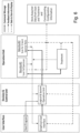
- Figure 1 shows a configuration of the apparatus of the first aspect of the invention, the apparatus being used for monitoring and treating cataracts.
- the core configuration of the apparatus comprises monitoring and treating light sources, a wavelength selection system and a dichroic beam splitter, wherein the monitoring light, the treating light and the excited fluorescence light are reflected by the dichroic beam splitter along a common optical axis.
- the dichroic beam splitter serves to reflect the monitoring light and the treating light towards the cataracts and the excited fluorescence light in the cataracts towards the wavelength selection system and is arranged at 45 degrees to the common optical axis to transmit wavelengths longer than wavelengths of the monitoring light, the treating light and the excited fluorescence light towards an operator of the apparatus.
- the apparatus (100) is shown to comprise:
- the treating light source (40) is configured to treat cataracts by emitting treating light in the wavelength range of 400 to 570 nm to irradiate the cataracts.
- the treating light source (40) comprises a non-lasing LED light source operable to emit light in the wavelength range of 400 to 570 nm, preferably in the wavelength range of 410 to 420 nm and more preferably at 415 nm or 420 nm to irradiate the cataracts.
- the treating wavelength of 420 nm has been used in pre-clinical trials on removed pig's lenses, whereas the treating wavelength of 415 nm has been used in both pre-clinical trials (on removed pig's lenses and on diabetic live pig's lenses) and in clinical trials.
- Treating the cataractic lens is also known as photo-bleaching.
- LEDs provides for a non-invasive photo-bleaching treatment that retains the natural lens.
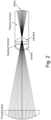
- a 'ray trace' experiment was carried out to determine the intensity of the treating light at the retina.
- Figure 2 illustrates a ray trace showing that the LED beam will focus on the lens and defocus over the retina, therefore a reduced power density is seen by the retina compared to the treatment volume in the lens. This, in turn, drastically reduces the chance of retinal damage.
- the treating dichroic beam splitter (44) is operable to reflect the emitted treating light onto the cataracts.
- the treating dichroic beam splitter (44) is a 420/425 nm dichroic and it reflects the treating light at 415 or 420 nm down the common optical axis as the monitoring light, whilst passing wavelengths above 420 nm. This enables the apparatus (100) to simultaneously monitor the treatment effect of the 415nm or 420 nm LED.
- a MEMS mirror system (not shown) may be used and is operable to move the emitted treating light around various parts of the cataract to treat all types of cataract.
- This arrangement requires the use of a slit-lamp microscope camera to enable targeting various parts of the eye with the treating light beam.
- the monitoring light source (50) is configured to monitor cataracts by emitting monitoring light in the wavelength range of 350 to 410 nm to excite fluorescence light in the cataracts.
- the monitoring light source (50) comprises a non-lasing LED light source operable to emit light in the wavelength range of 350 to 410 nm, preferably in the wavelength range of 360 to 370 nm and more preferably at 365 nm to excite fluorescence light in the cataracts.
- the monitoring wavelength of 365 nm has been used in both pre-clinical trials (on removed pig's lenses and diabetic live pig's lenses) and in clinical trials.
- the monitoring dichroic beam splitter (54) is operable to reflect the emitted monitoring light onto the cataracts.
- the monitoring dichroic beam splitter (54) is a 395 nm dichroic and it reflects the monitoring light at 365 nm down the common optical axis as the treating light, whilst passing wavelengths above 395 nm, including the treating light at 415 nm or 420 nm and the NFK fluorescence peak at around 440 nm. This enables the apparatus (100) to simultaneously monitor the treatment effect of the 415nm or 420 nm LED.
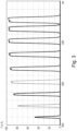
- the wavelength selection system (20) comprises a wedge filter (22), which is a tuneable bandpass interference filter operable in the wavelength range of 320 to 560 nm.
- Figure 3 shows the 320 to 560 nm spectrum of the wedge filter (22).
- the spectral measurements were performed using a 0.2 mm spot width and 1.0 nm spectral bandwidth.
- the wavelength range of the wedge filter (22) was carefully chosen to allow the environmentally broadened emissions of the tryptophan and NFK to be recorded without distortion.
- the chosen bandwidth of the wedge filter (22) is wider than what is normal for fluorescence interference filters, therefore providing the wavelength selection system (20) with greater sensitivity in a miniaturised system.
- the wavelength selection system (20) may comprise a diffraction grating as an alternative to the wedge filter (22).
- the wavelength selection system (20) further comprises a phase-sensitive detection system (not shown) operable at the same pulse frequency as a pulse frequency of the monitoring light source (50) to separate wavelengths of the excited fluorescence light from wavelengths of ambient light.
- the phase-sensitive detection system may be a lock-in amplifier.
- the ability to operate the apparatus (100) under ambient lighting conditions will remove the requirement of strictly controlled environmental lighting conditions. This should greatly increase the number of suitable locations where the apparatus (100) can operate.
- the phase-sensitive detection system is a system whereby the excitation light from the system is modulated. The system is then able to differentiate between the reflected, modulated light necessary for cataract diagnosis and the ambient, unmodulated light that would otherwise interfere.
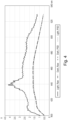
- Figure 4 shows the data obtained from the above experiment and illustrates the effect on the recorded fluorescence spectra (400 nm to 530 nm) of a lock-in amplifier employed in an embodiment of the wavelength selection system (20) of the apparatus (100).
- Line frequency of ambient lights varies by country; however, it is generally either 50Hz or 60Hz depending on region. Fluorescent room lighting in the UK shows a peak at 100Hz caused by 50Hz line frequency exciting the tube twice per cycle. An apparent harmonic also appears at 200Hz. Therefore,
- a PSD system operating frequency of 165Hz should be optimum for both 50Hz and 60Hz line frequencies.
- the wavelength selection system (20) further comprises a linear drive (not shown) operable to move the linear variable interference filter (wedge filter (22) in Figure 1 ) along an axis perpendicular to the common optical axis.
- the detector (10) is a single detector, typically a PMT detector.
- the linear variable interference filter (wedge filter (22) in Figure 1 ) of the wavelength selection system (20) is operable from a fixed position on the common optical axis.
- the detector (10) is a one-dimensional or a two-dimensional array of detectors (10).
- the dichroic beam splitter (70) is arranged at 45 degrees to the common optical axis to transmit wavelengths longer than wavelengths of the monitoring light, the treating light and the excited fluorescence light towards an operator (not shown) of the apparatus (100).
- This arrangement is necessary in order to allow the operator to simply swing the apparatus (100) in and out of a slit-lamp microscope (90).
- the apparatus (100) is mounted onto a rotation stage with visible markings every 1 degree and a hard stop at the 0-degree (or 'in use') position. This allows the apparatus (100) to be moved out of the way of the slit-lamp (90) and moved back when monitoring or treatment is to be carried out on the eye (80).
- the dichroic beam splitter (70) is a 563 nm dichroic and it reflects the required short-wavelength monitoring and treating lights towards the eye (80), whilst allowing long-wavelength visible light to pass through to (i.e., be transmitted towards) the slit-lamp microscope (90) so that a visual (or camera) check on the positioning of the patient's eye (80) can be maintained.
- This allows the use of a computerised tracking system using the image captured by the camera built into the slip-lamp microscope (90).
- the tracking software alerts the operator when the eye moves out of position, this in turn, allowing better control of the actual treatment dose for the patient.
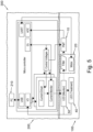
- Figure 5 shows a configuration of the system (300) for use in monitoring and treating cataracts, the system (300) being shown to comprise:
- the monitoring LED (at 365nm) and the treating LED (at 415 nm or 420 nm) are permanently installed in the system (100) and controlled by bespoke software implemented by the electronic device (200).
- each LED has a bandwidth larger than 10 nm
- each light beam is filtered by a hard-coated optical filter (not shown) centered near the emission wavelength of each of the LEDs. This reduces unwanted light from entering the apparatus (100).
- the output of the apparatus (100) to the patient is further filtered by the dichroics (44), (54) and (70) used to fold and direct the internal LED beam paths along a common optical axis. These dichroics are hard coated.
- Figure 5 also shows relevant components of the electronic device (200), namely the data storage and processing device (210).
- the device (210) is adapted for communication with the wavelength selection system (20) of the apparatus (100) and is configured:
- the apparatus (100) is configured by the electronic device (200) to successively monitor cataracts using the monitoring light source (50) and to treat cataracts using the treating light source (40). Therefore, the operating mode of the apparatus (100) may be selected from
- the apparatus (100) is mounted onto a rotation stage (not shown) with visible markings every 1 degree and a hard stop at the 0-degree (or 'in use') position. This allows the apparatus (100) to be moved out of the way of the slit-lamp microscope (90) and moved back when monitoring or treatment is to be carried out on the eye (80).
- the apparatus (100) is used efficiently for cataract assessment by determining fluorescence changes within the cataractous eye (80) caused by the 365 nm monitoring LED (50) exciting the fluorescence within the eye (80).
- the fluorescence signals return from the patient's eye (80) and are transmitted by the dichroic reflector (70) to give fluorescence spectra at the PMT detector (10).
- the spectra are analysed to determine the extent of the patient's cataract. Therefore, through the use of fluorescence spectra, the operator of the apparatus (100) can efficiently and effectively monitor the cataract changes resulting from treatment with the treating light LED (40) of the apparatus (100).
- the apparatus (100) focusses the 415nm treating LED (40) onto the patient's cataract for a treatment period of up to 2 hours, which is split into sessions of no longer than 15 minutes per session.
- Figure 6 illustrates the software architectural design employed by the electronic device (200) of the system (300).
- the software firstly establishes a communication channel between the apparatus (100) and the data storage and processing device (210). Using that communication channel, the software can send instructions to the device (210) as well as receive spectral data and the instantaneous status of the apparatus (100).
- the software has a control unit which uses the communication channel to control, validate and monitor the sequence of tasks for any operation.
- the software has been developed to perform three key operations, as described below:
- the software sequentially performs the following tasks:
- the software does similar steps as the Full Scan Monitor but, in this case, the average value of each band's data and its ratio will be displayed instead of full spectrum.
- the monitoring mode of the apparatus (100) may comprise any one or a combination of any one of a spectral scan mode or a ratio scan mode.
- the apparatus (100) may be configured to simultaneously monitor cataracts using the monitoring light source (50) and treat cataracts using the treating light source (40).
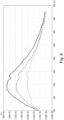
- Figure 7 shows fluorescence spectra recorded on a removed pig's lens using a first configuration of the apparatus (100).
- the measurement protocol was such that a cataract was first induced in the lens by irradiating the lens with UV light at 310 nm for 2 hours. The cataract was then treated (or photo-bleached) with treating light at 415 nm.
- the fluorescence spectra of the different conditions of the removed lens have been recorded with monitoring (or excitation) light at 365 nm and are shown in Figure 7 for - a fresh lens (dotted line), a cataractic lens (solid line) and a treated lens (dashed line).
- the treated lens displays a fluorescence spectrum very similar to that of the fresh lens.
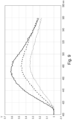
- Figure 8 shows other fluorescence spectra recorded on another removed pig's lens using a second configuration of the apparatus (100).
- the protocol followed was to first induce a cataract in the lens by irradiation at 310 nm for 2 hours. However, in this configuration, the cataract was then treated with treating light at 420 nm for 2 hours.
- the fluorescence spectra of the different conditions of the removed lens have also been recorded with monitoring light at 365 nm and are shown in Figure 8 for - a fresh lens (dotted line), a cataractic lens (solid line) and a treated lens (dashed line).
- Figure 9 shows fluorescence spectra recorded on a live diabetic pig's lens using the first configuration of the apparatus (100).
- the measurement protocol was different because the lens of the live pig was already cataractic since cataracts are one of the sight-related complications of diabetes. Therefore, the cataract was treated with treating light at 415 nm for an initial period of 1 hour, followed by another treatment period of another hour.
- the fluorescence spectra of the cataractic lens and of the lens treated in two consecutive 1-hour sessions have been recorded with monitoring light at 365 nm and are shown in Figure 9 for - a cataractic live lens (solid line), a lens treated for 1 hour (dashed line) and a lens treated for another hour (dotted line).
- a cataractic live lens solid line
- a lens treated for 1 hour dashed line
- a lens treated for another hour dotted line
- the treating light source (40) and/ or the monitoring light source (50) may comprise a low power laser source or any combination of a polychromatic light source and suitable wavelength selection system.
Landscapes
- Health & Medical Sciences (AREA)
- Life Sciences & Earth Sciences (AREA)
- Engineering & Computer Science (AREA)
- Biomedical Technology (AREA)
- Public Health (AREA)
- Veterinary Medicine (AREA)
- Animal Behavior & Ethology (AREA)
- General Health & Medical Sciences (AREA)
- Ophthalmology & Optometry (AREA)
- Surgery (AREA)
- Heart & Thoracic Surgery (AREA)
- Physics & Mathematics (AREA)
- Medical Informatics (AREA)
- Biophysics (AREA)
- Molecular Biology (AREA)
- Nuclear Medicine, Radiotherapy & Molecular Imaging (AREA)
- Pathology (AREA)
- Radiology & Medical Imaging (AREA)
- Optics & Photonics (AREA)
- Electromagnetism (AREA)
- Vascular Medicine (AREA)
- Investigating, Analyzing Materials By Fluorescence Or Luminescence (AREA)
- Cash Registers Or Receiving Machines (AREA)
Claims (21)
- Vorrichtung (100) zur Überwachung und Behandlung von Katarakten, wobei die Vorrichtung (100) umfasst:eine Überwachungslichtquelle (50), die konfiguriert ist zum Überwachen von Katarakten durch Emittieren von Überwachungslicht im Wellenlängenbereich von 350 bis 410 nm, um Fluoreszenzlicht in den Katarakten anzuregeneine Behandlungslichtquelle (40), die konfiguriert ist zum Behandeln von Katarakten durch Emittieren von Behandlungslicht im Wellenlängenbereich von 400 bis 570 nm, um die Katarakte zu bestrahlenein Wellenlängenauswahlsystem (20), das konfiguriert ist zum Überwachen von Katarakten durch Auswählen von Wellenlängen des angeregten Fluoreszenzlichts in den Katarakten, undeinen dichroitischen Strahlteiler (70), der konfiguriert ist zum Reflektieren des Überwachungslichts und des Behandlungslichts in Richtung der Katarakte und des angeregten Fluoreszenzlichts in den Katarakten in Richtung des Wellenlängenauswahlsystems (20)wobei das Überwachungslicht, das Behandlungslicht und das angeregte Fluoreszenzlicht von dem dichroitischen Strahlteiler (70) entlang einer gemeinsamen optischen Achse reflektiert werden undwobei der dichroitische Strahlteiler (70) unter 45 Grad zu der gemeinsamen optischen Achse angeordnet ist, um Wellenlängen, die länger sind als Wellenlängen des Überwachungslichts, des Behandlungslichts und des angeregten Fluoreszenzlichts, in Richtung eines Bedieners der Vorrichtung (100) zu übertragen.
- Vorrichtung (100) nach Anspruch 1, wobei die Überwachungslichtquelle (50) eine nicht-lasernde LED-Lichtquelle umfasst, die betreibbar ist, um Licht im Wellenlängenbereich von 350 bis 410 nm, bevorzugt im Wellenlängenbereich von 360 bis 370 nm und bevorzugter bei 365 nm zu emittieren, um Fluoreszenzlicht in den Katarakten anzuregen.
- Vorrichtung (100) nach einem der vorhergehenden Ansprüche, wobei die Behandlungslichtquelle (40) eine nicht-lasernde LED-Lichtquelle umfasst, die betreibbar ist, um Licht im Wellenlängenbereich von 400 bis 570 nm, bevorzugt im Wellenlängenbereich von 410 bis 420 nm und bevorzugter bei 415 nm zu emittieren, um die Katarakte zu bestrahlen.
- Vorrichtung (100) nach einem der vorhergehenden Ansprüche, wobei das Wellenlängenauswahlsystem (20) einen beliebigen oder eine Kombination aus einem beliebigen eines linearen variablen Interferenzfilters, eines Beugungsgitters und eines refraktiven Prismas umfasst.
- Vorrichtung (100) nach Anspruch 4, wobei der lineare variable Interferenzfilter (22) einen durchstimmbaren Bandpass-Interferenzfilter umfasst, der im Wellenlängenbereich von 320 bis 560 nm betreibbar ist.
- Vorrichtung (100) nach Anspruch 5, wobei der durchstimmbare Bandpass-Interferenzfilter einen Keilfilter (22) umfasst.
- Vorrichtung (100) nach einem der Ansprüche 4 bis 6, wobei das Wellenlängenauswahlsystem (20) ferner einen Linearantrieb umfasst, der betreibbar ist, um den linearen variablen Interferenzfilter entlang einer Achse zu bewegen, die senkrecht zur gemeinsamen optischen Achse ist.
- Vorrichtung (100) nach einem der Ansprüche 4 bis 7, wobei die Vorrichtung (100) ferner einen Detektor (10) umfasst.
- Vorrichtung (100) nach einem der Ansprüche 4 bis 6, wobei der lineare variable Interferenzfilter von einer festen Position auf der gemeinsamen optischen Achse aus betreibbar ist.
- Vorrichtung (100) nach einem der Ansprüche 4 bis 6 und Anspruch 9, wobei die Vorrichtung (100) ferner eine eindimensionale oder zweidimensionale Anordnung von Detektoren (10) umfasst.
- Vorrichtung (100) nach einem der Ansprüche 4 bis 10, wobei das Wellenlängenauswahlsystem (20) ferner ein phasenempfindliches Detektionssystem umfasst, das bei der gleichen Impulsfrequenz wie eine Impulsfrequenz der Überwachungslichtquelle (50) betreibbar ist, um Wellenlängen des angeregten Fluoreszenzlichts von Wellenlängen des Umgebungslichts zu trennen.
- Vorrichtung (100) nach Anspruch 11, wobei das phasenempfindliche Detektionssystem einen Lock-in-Verstärker umfasst.
- Vorrichtung (100) nach einem der vorhergehenden Ansprüche, wobei die Vorrichtung (100) konfiguriert ist zum gleichzeitigen Überwachen von Katarakten unter Verwendung der Überwachungslichtquelle (50) und Behandeln von Katarakten unter Verwendung der Behandlungslichtquelle (40).
- Vorrichtung (100) nach einem der vorhergehenden Ansprüche, wobei die Vorrichtung (100) ferner einen dichroitischen Behandlungsstrahlteiler (44) umfasst, der betreibbar ist, um das emittierte Behandlungslicht auf die Katarakte zu reflektieren.
- Vorrichtung (100) nach einem der Ansprüche 1 bis 13, wobei die Vorrichtung (100) ferner ein MEMS-Spiegelsystem umfasst, das betreibbar ist, um das emittierte Behandlungslicht um verschiedene Teile des Katarakts herum zu bewegen.
- Vorrichtung (100) nach einem der Ansprüche 1-15, wobei das Wellenlängenauswahlsystem (20) einen beliebigen oder eine Kombination aus einem beliebigen eines linearen variablen Interferenzfilters, eines Beugungsgitters und eines refraktiven Prismas umfasst.
- Vorrichtung (100) nach Anspruch 16, wobei der lineare variable Interferenzfilter einen durchstimmbaren Bandpass-Interferenzfilter umfasst, der im Wellenlängenbereich von 320 bis 560 nm betreibbar ist.
- Vorrichtung (100) nach Anspruch 17, wobei der durchstimmbare Bandpass-Interferenzfilter einen Keilfilter (22) umfasst.
- System (300) zur Verwendung bei der Überwachung und Behandlung von Katarakten, wobei das System die Vorrichtung (100) zur Überwachung und Behandlung von Katarakten nach einem der Ansprüche 1 bis 17 und ein elektronisches Gerät (200) umfasst,
wobei das elektronische Gerät (200) ein Datenspeicherungs- und -verarbeitungsgerät (210) umfasst, das für die Kommunikation mit dem Wellenlängenauswahlsystem (20) der Vorrichtung (100) ausgelegt und konfiguriert ist:(i) zum Verwalten der Stromversorgung einer oder beider der Überwachungslichtquelle (50) und der Behandlungslichtquelle (40),(ii) zum Steuern von Einwirkungszeiten zur Anregung von Fluoreszenzlicht in den Katarakten mit der Überwachungslichtquelle (50)(iii) zum Steuern von Einwirkungszeiten für die Bestrahlung der Katarakte mit der Behandlungslichtquelle (40) und(iv) zum Auswählen eines Betriebsmodus der Vorrichtung (100). - System (300) nach Anspruch 19,
wobei der Betriebsmodus der Vorrichtung (100) ausgewählt ist aus- einem Überwachungsmodus, in dem das elektronische Gerät (200) die Stromversorgung und die Einwirkungszeit der Überwachungslichtquelle (50) verwaltet und steuert, oder- einem Behandlungsmodus, in dem das elektronische Gerät (200) die Stromversorgung und die Einwirkungszeit der Behandlungslichtquelle (40) verwaltet und steuert. - System nach Anspruch 20,
wobei der Überwachungsmodus der Vorrichtung (100) einen beliebigen oder eine Kombination aus einem beliebigen eines Spektral-Scan-Modus oder eines Verhältnis-Scan-Modus umfasst.
Priority Applications (2)
| Application Number | Priority Date | Filing Date | Title |
|---|---|---|---|
| SI202130302T SI4284230T1 (sl) | 2021-01-26 | 2021-05-27 | Naprava in sistemi za spremljanje in zdravljenje sive mrene |
| HRP20250473TT HRP20250473T1 (hr) | 2021-01-26 | 2021-05-27 | Aparati i sustavi za praćenje i liječenje katarakte |
Applications Claiming Priority (2)
| Application Number | Priority Date | Filing Date | Title |
|---|---|---|---|
| GB2101007.9A GB2603006B (en) | 2021-01-26 | 2021-01-26 | Apparatus and systems for monitoring and treating cataracts |
| PCT/EP2021/064249 WO2022161647A1 (en) | 2021-01-26 | 2021-05-27 | Apparatus and systems for monitoring and treating cataracts |
Publications (2)
| Publication Number | Publication Date |
|---|---|
| EP4284230A1 EP4284230A1 (de) | 2023-12-06 |
| EP4284230B1 true EP4284230B1 (de) | 2025-02-19 |
Family
ID=79248985
Family Applications (1)
| Application Number | Title | Priority Date | Filing Date |
|---|---|---|---|
| EP21731407.9A Active EP4284230B1 (de) | 2021-01-26 | 2021-05-27 | Vorrichtungen und systeme zur überwachung und behandlung von katarakt |
Country Status (11)
| Country | Link |
|---|---|
| US (1) | US20240090763A1 (de) |
| EP (1) | EP4284230B1 (de) |
| CN (1) | CN113924143A (de) |
| AU (1) | AU2021422913A1 (de) |
| DK (1) | DK4284230T3 (de) |
| ES (1) | ES3025137T3 (de) |
| FI (1) | FI4284230T3 (de) |
| HR (1) | HRP20250473T1 (de) |
| LT (1) | LT4284230T (de) |
| PL (1) | PL4284230T3 (de) |
| SI (1) | SI4284230T1 (de) |
Family Cites Families (16)
| Publication number | Priority date | Publication date | Assignee | Title |
|---|---|---|---|---|
| JPS5435434B2 (de) * | 1973-11-13 | 1979-11-02 | ||
| US4412543A (en) * | 1981-04-09 | 1983-11-01 | Xanar, Inc. | Apparatus for determining the concentration of a fluorescent material in an eye |
| DE102004022605A1 (de) * | 2004-05-07 | 2005-12-08 | Olympus Biosystems Gmbh | Optische Objektuntersuchungseinrichtung mit mehreren auf Grundlage wenigstens eines polarisierenden Strahlteilers gebildeten Strahlengängen |
| US7918559B2 (en) * | 2005-04-29 | 2011-04-05 | Novadaq Technologies Inc. | Choroid and retinal imaging and treatment system |
| CN101110910B (zh) * | 2006-07-21 | 2010-06-16 | 田承仁 | 红外激光拍摄装置 |
| EP2094208B1 (de) * | 2006-11-10 | 2013-09-04 | Lars Michael Larsen | Gerät zur nicht- oder minimal-disruptiven lichtmanipulation eines auges |
| US20110202114A1 (en) * | 2008-08-08 | 2011-08-18 | Line Kessel | System and method for treatment of lens related disorders |
| WO2012024188A1 (en) * | 2010-08-16 | 2012-02-23 | Neuroptix Corporation | System and method for detecting amyloid proteins |
| US9521949B2 (en) * | 2011-06-23 | 2016-12-20 | Amo Development, Llc | Ophthalmic range finding |
| US9381116B2 (en) * | 2012-05-25 | 2016-07-05 | Ojai Retinal Technology, Llc | Subthreshold micropulse laser prophylactic treatment for chronic progressive retinal diseases |
| US9713423B2 (en) * | 2013-03-15 | 2017-07-25 | The Johns Hopkins University | Apparatus and method for minimizing the influence of corneal birefringence on the analysis of eye fixation and focus using retinal birefringence scanning |
| WO2014181744A1 (ja) * | 2013-05-08 | 2014-11-13 | 株式会社島津製作所 | 蛍光測定装置及び蛍光測定方法 |
| GB201323130D0 (en) * | 2013-12-30 | 2014-02-12 | Univ Heriot Watt | Non-invasive eye test |
| CN104614318A (zh) * | 2015-01-28 | 2015-05-13 | 浙江大学 | 一种快速的超分辨显微成像方法和装置 |
| GB201522555D0 (en) * | 2015-12-21 | 2016-02-03 | Edinburgh Biosciences Ltd | Eye treatment system |
| CN108743020A (zh) * | 2018-06-28 | 2018-11-06 | 百锐明医疗科技(北京)有限公司 | 眼科激光治疗设备 |
-
2021
- 2021-05-27 LT LTEPPCT/EP2021/064249T patent/LT4284230T/lt unknown
- 2021-05-27 EP EP21731407.9A patent/EP4284230B1/de active Active
- 2021-05-27 HR HRP20250473TT patent/HRP20250473T1/hr unknown
- 2021-05-27 AU AU2021422913A patent/AU2021422913A1/en active Pending
- 2021-05-27 FI FIEP21731407.9T patent/FI4284230T3/fi active
- 2021-05-27 CN CN202180002521.9A patent/CN113924143A/zh active Pending
- 2021-05-27 SI SI202130302T patent/SI4284230T1/sl unknown
- 2021-05-27 DK DK21731407.9T patent/DK4284230T3/da active
- 2021-05-27 US US18/263,088 patent/US20240090763A1/en active Pending
- 2021-05-27 ES ES21731407T patent/ES3025137T3/es active Active
- 2021-05-27 PL PL21731407.9T patent/PL4284230T3/pl unknown
Also Published As
| Publication number | Publication date |
|---|---|
| HRP20250473T1 (hr) | 2025-08-01 |
| FI4284230T3 (fi) | 2025-04-24 |
| ES3025137T3 (en) | 2025-06-06 |
| LT4284230T (lt) | 2025-05-26 |
| EP4284230A1 (de) | 2023-12-06 |
| SI4284230T1 (sl) | 2025-08-29 |
| PL4284230T3 (pl) | 2025-06-23 |
| DK4284230T3 (da) | 2025-04-28 |
| AU2021422913A1 (en) | 2023-09-07 |
| US20240090763A1 (en) | 2024-03-21 |
| CN113924143A (zh) | 2022-01-11 |
Similar Documents
| Publication | Publication Date | Title |
|---|---|---|
| CN102014732B (zh) | 用于观察、检查、诊断和/或治疗眼睛的眼科设备 | |
| JP5227811B2 (ja) | 眼科機器 | |
| CA2263262C (en) | Method and system for measurement of macular carotenoid levels | |
| KR101471579B1 (ko) | 눈의 비파괴성 또는 최소 파괴성 광처리 장치 | |
| JP3850192B2 (ja) | 眼底撮影装置 | |
| AU2016378925B2 (en) | Eye treatment system | |
| JPS59225057A (ja) | 治療用光線としてのレ−ザ−光線を用いて眼底で光凝固する際に線量を測定する方法及び装置 | |
| JP2005514137A (ja) | 黄斑色素のラマン画像を作成する方法と装置 | |
| EP1011416B1 (de) | Gerät zur messung der autofluoreszenz der augenhornhaut | |
| EP4284230B1 (de) | Vorrichtungen und systeme zur überwachung und behandlung von katarakt | |
| Zuclich et al. | In situ measurements of lens fluorescence and its interference with visual function. | |
| HK40077485A (en) | Apparatus and systems for monitoring and treating cataracts | |
| TWI844819B (zh) | 波長選擇系統以及用於監測和治療白內障的設備和系統 | |
| HK40069417A (en) | Apparatus and systems for monitoring and treating cataracts | |
| Zuclich | In-vivo measurements of optical properties of the ocular lens | |
| RU2651126C1 (ru) | Способ раннего выявления возрастной макулярной дистрофии сетчатки | |
| KR102080786B1 (ko) | 편광 빔 스플리터와 선형편광필터를 사용한 플루오레세인 형광 안저 혈관조영장치 | |
| Schweitzer et al. | Fluorescence Lifetime Imaging in Ophthalmology | |
| CN121129177A (zh) | 一种多光谱荧光内窥镜成像系统和方法 | |
| Hochheimer | A Study of Low Level Laser Retinal Damage. | |
| Sun et al. | Autofluorescence Lifetime Imaging of Retinal Pigment Epithelium Cells Using Two-photon Excitation | |
| JPS6351019B2 (de) |
Legal Events
| Date | Code | Title | Description |
|---|---|---|---|
| REG | Reference to a national code |
Ref country code: HR Ref legal event code: TUEP Ref document number: P20250473T Country of ref document: HR |
|
| STAA | Information on the status of an ep patent application or granted ep patent |
Free format text: STATUS: UNKNOWN |
|
| STAA | Information on the status of an ep patent application or granted ep patent |
Free format text: STATUS: THE INTERNATIONAL PUBLICATION HAS BEEN MADE |
|
| PUAI | Public reference made under article 153(3) epc to a published international application that has entered the european phase |
Free format text: ORIGINAL CODE: 0009012 |
|
| STAA | Information on the status of an ep patent application or granted ep patent |
Free format text: STATUS: REQUEST FOR EXAMINATION WAS MADE |
|
| 17P | Request for examination filed |
Effective date: 20230817 |
|
| AK | Designated contracting states |
Kind code of ref document: A1 Designated state(s): AL AT BE BG CH CY CZ DE DK EE ES FI FR GB GR HR HU IE IS IT LI LT LU LV MC MK MT NL NO PL PT RO RS SE SI SK SM TR |
|
| DAV | Request for validation of the european patent (deleted) | ||
| DAX | Request for extension of the european patent (deleted) | ||
| RIC1 | Information provided on ipc code assigned before grant |
Ipc: A61B 3/00 20060101ALI20240717BHEP Ipc: A61B 3/13 20060101ALI20240717BHEP Ipc: A61N 5/06 20060101ALI20240717BHEP Ipc: A61F 9/007 20060101ALI20240717BHEP Ipc: A61B 3/117 20060101AFI20240717BHEP |
|
| GRAP | Despatch of communication of intention to grant a patent |
Free format text: ORIGINAL CODE: EPIDOSNIGR1 |
|
| STAA | Information on the status of an ep patent application or granted ep patent |
Free format text: STATUS: GRANT OF PATENT IS INTENDED |
|
| INTG | Intention to grant announced |
Effective date: 20240916 |
|
| GRAS | Grant fee paid |
Free format text: ORIGINAL CODE: EPIDOSNIGR3 |
|
| GRAA | (expected) grant |
Free format text: ORIGINAL CODE: 0009210 |
|
| STAA | Information on the status of an ep patent application or granted ep patent |
Free format text: STATUS: THE PATENT HAS BEEN GRANTED |
|
| P01 | Opt-out of the competence of the unified patent court (upc) registered |
Free format text: CASE NUMBER: APP_213/2025 Effective date: 20250103 |
|
| AK | Designated contracting states |
Kind code of ref document: B1 Designated state(s): AL AT BE BG CH CY CZ DE DK EE ES FI FR GB GR HR HU IE IS IT LI LT LU LV MC MK MT NL NO PL PT RO RS SE SI SK SM TR |
|
| REG | Reference to a national code |
Ref country code: GB Ref legal event code: FG4D |
|
| REG | Reference to a national code |
Ref country code: CH Ref legal event code: EP |
|
| REG | Reference to a national code |
Ref country code: IE Ref legal event code: FG4D |
|
| REG | Reference to a national code |
Ref country code: DE Ref legal event code: R096 Ref document number: 602021026385 Country of ref document: DE |
|
| REG | Reference to a national code |
Ref country code: PT Ref legal event code: SC4A Ref document number: 4284230 Country of ref document: PT Date of ref document: 20250422 Kind code of ref document: T Free format text: AVAILABILITY OF NATIONAL TRANSLATION Effective date: 20250415 |
|
| REG | Reference to a national code |
Ref country code: FI Ref legal event code: FGE |
|
| REG | Reference to a national code |
Ref country code: DK Ref legal event code: T3 Effective date: 20250424 |
|
| RAP4 | Party data changed (patent owner data changed or rights of a patent transferred) |
Owner name: EDINBURGH BIOSCIENCES LIMITED |
|
| REG | Reference to a national code |
Ref country code: NL Ref legal event code: FP |
|
| PGFP | Annual fee paid to national office [announced via postgrant information from national office to epo] |
Ref country code: NL Payment date: 20250414 Year of fee payment: 5 |
|
| PGFP | Annual fee paid to national office [announced via postgrant information from national office to epo] |
Ref country code: LU Payment date: 20250416 Year of fee payment: 5 |
|
| REG | Reference to a national code |
Ref country code: SE Ref legal event code: TRGR |
|
| REG | Reference to a national code |
Ref country code: HR Ref legal event code: ODRP Ref document number: P20250473T Country of ref document: HR Payment date: 20250422 Year of fee payment: 5 Ref country code: ES Ref legal event code: FG2A Ref document number: 3025137 Country of ref document: ES Kind code of ref document: T3 Effective date: 20250606 |
|
| PG25 | Lapsed in a contracting state [announced via postgrant information from national office to epo] |
Ref country code: RS Free format text: LAPSE BECAUSE OF FAILURE TO SUBMIT A TRANSLATION OF THE DESCRIPTION OR TO PAY THE FEE WITHIN THE PRESCRIBED TIME-LIMIT Effective date: 20250519 |
|
| PGFP | Annual fee paid to national office [announced via postgrant information from national office to epo] |
Ref country code: MC Payment date: 20250425 Year of fee payment: 5 |
|
| PGFP | Annual fee paid to national office [announced via postgrant information from national office to epo] |
Ref country code: FI Payment date: 20250417 Year of fee payment: 5 |
|
| PGFP | Annual fee paid to national office [announced via postgrant information from national office to epo] |
Ref country code: DE Payment date: 20250416 Year of fee payment: 5 Ref country code: PL Payment date: 20250411 Year of fee payment: 5 |
|
| PGFP | Annual fee paid to national office [announced via postgrant information from national office to epo] |
Ref country code: GB Payment date: 20250521 Year of fee payment: 5 Ref country code: ES Payment date: 20250610 Year of fee payment: 5 Ref country code: DK Payment date: 20250425 Year of fee payment: 5 |
|
| PGFP | Annual fee paid to national office [announced via postgrant information from national office to epo] |
Ref country code: LT Payment date: 20250414 Year of fee payment: 5 |
|
| PGFP | Annual fee paid to national office [announced via postgrant information from national office to epo] |
Ref country code: IS Payment date: 20250414 Year of fee payment: 5 Ref country code: HU Payment date: 20250418 Year of fee payment: 5 Ref country code: NO Payment date: 20250422 Year of fee payment: 5 |
|
| PGFP | Annual fee paid to national office [announced via postgrant information from national office to epo] |
Ref country code: AL Payment date: 20250424 Year of fee payment: 5 Ref country code: IT Payment date: 20250424 Year of fee payment: 5 Ref country code: BE Payment date: 20250411 Year of fee payment: 5 |
|
| PGFP | Annual fee paid to national office [announced via postgrant information from national office to epo] |
Ref country code: HR Payment date: 20250422 Year of fee payment: 5 |
|
| PGFP | Annual fee paid to national office [announced via postgrant information from national office to epo] |
Ref country code: PT Payment date: 20250423 Year of fee payment: 5 Ref country code: LV Payment date: 20250413 Year of fee payment: 5 |
|
| PGFP | Annual fee paid to national office [announced via postgrant information from national office to epo] |
Ref country code: FR Payment date: 20250411 Year of fee payment: 5 |
|
| PG25 | Lapsed in a contracting state [announced via postgrant information from national office to epo] |
Ref country code: BG Free format text: LAPSE BECAUSE OF FAILURE TO SUBMIT A TRANSLATION OF THE DESCRIPTION OR TO PAY THE FEE WITHIN THE PRESCRIBED TIME-LIMIT Effective date: 20250219 |
|
| PGFP | Annual fee paid to national office [announced via postgrant information from national office to epo] |
Ref country code: MT Payment date: 20250411 Year of fee payment: 5 Ref country code: GR Payment date: 20250516 Year of fee payment: 5 |
|
| PGFP | Annual fee paid to national office [announced via postgrant information from national office to epo] |
Ref country code: CH Payment date: 20250625 Year of fee payment: 5 |
|
| PGFP | Annual fee paid to national office [announced via postgrant information from national office to epo] |
Ref country code: RO Payment date: 20250417 Year of fee payment: 5 |
|
| PGFP | Annual fee paid to national office [announced via postgrant information from national office to epo] |
Ref country code: CZ Payment date: 20250411 Year of fee payment: 5 |
|
| PGFP | Annual fee paid to national office [announced via postgrant information from national office to epo] |
Ref country code: IE Payment date: 20250415 Year of fee payment: 5 |
|
| PGFP | Annual fee paid to national office [announced via postgrant information from national office to epo] |
Ref country code: SI Payment date: 20250411 Year of fee payment: 5 Ref country code: SE Payment date: 20250415 Year of fee payment: 5 |
|
| REG | Reference to a national code |
Ref country code: HR Ref legal event code: T1PR Ref document number: P20250473 Country of ref document: HR |
|
| REG | Reference to a national code |
Ref country code: EE Ref legal event code: FG4A Ref document number: E025062 Country of ref document: EE Effective date: 20250422 Ref country code: AT Ref legal event code: MK05 Ref document number: 1767504 Country of ref document: AT Kind code of ref document: T Effective date: 20250219 |
|
| REG | Reference to a national code |
Ref country code: GR Ref legal event code: EP Ref document number: 20250400948 Country of ref document: GR Effective date: 20250613 |
|
| REG | Reference to a national code |
Ref country code: HU Ref legal event code: AG4A Ref document number: E071210 Country of ref document: HU |
|
| PG25 | Lapsed in a contracting state [announced via postgrant information from national office to epo] |
Ref country code: SM Free format text: LAPSE BECAUSE OF FAILURE TO SUBMIT A TRANSLATION OF THE DESCRIPTION OR TO PAY THE FEE WITHIN THE PRESCRIBED TIME-LIMIT Effective date: 20250219 |
|
| PG25 | Lapsed in a contracting state [announced via postgrant information from national office to epo] |
Ref country code: AT Free format text: LAPSE BECAUSE OF FAILURE TO SUBMIT A TRANSLATION OF THE DESCRIPTION OR TO PAY THE FEE WITHIN THE PRESCRIBED TIME-LIMIT Effective date: 20250219 |
|
| PGFP | Annual fee paid to national office [announced via postgrant information from national office to epo] |
Ref country code: EE Payment date: 20250714 Year of fee payment: 5 |
|
| PG25 | Lapsed in a contracting state [announced via postgrant information from national office to epo] |
Ref country code: SK Free format text: LAPSE BECAUSE OF FAILURE TO SUBMIT A TRANSLATION OF THE DESCRIPTION OR TO PAY THE FEE WITHIN THE PRESCRIBED TIME-LIMIT Effective date: 20250219 |
|
| PGFP | Annual fee paid to national office [announced via postgrant information from national office to epo] |
Ref country code: MK Payment date: 20250429 Year of fee payment: 5 |
|
| REG | Reference to a national code |
Ref country code: DE Ref legal event code: R097 Ref document number: 602021026385 Country of ref document: DE |
|
| PLBE | No opposition filed within time limit |
Free format text: ORIGINAL CODE: 0009261 |
|
| STAA | Information on the status of an ep patent application or granted ep patent |
Free format text: STATUS: NO OPPOSITION FILED WITHIN TIME LIMIT |
|
| 26N | No opposition filed |
Effective date: 20251120 |