EP4284162B1 - Trennwand für einen bienenstock - Google Patents
Trennwand für einen bienenstock Download PDFInfo
- Publication number
- EP4284162B1 EP4284162B1 EP22702002.1A EP22702002A EP4284162B1 EP 4284162 B1 EP4284162 B1 EP 4284162B1 EP 22702002 A EP22702002 A EP 22702002A EP 4284162 B1 EP4284162 B1 EP 4284162B1
- Authority
- EP
- European Patent Office
- Prior art keywords
- hive
- partition
- radiating
- radiating partition
- panel
- Prior art date
- Legal status (The legal status is an assumption and is not a legal conclusion. Google has not performed a legal analysis and makes no representation as to the accuracy of the status listed.)
- Active
Links
Images



Classifications
-
- A—HUMAN NECESSITIES
- A01—AGRICULTURE; FORESTRY; ANIMAL HUSBANDRY; HUNTING; TRAPPING; FISHING
- A01K—ANIMAL HUSBANDRY; AVICULTURE; APICULTURE; PISCICULTURE; FISHING; REARING OR BREEDING ANIMALS, NOT OTHERWISE PROVIDED FOR; NEW BREEDS OF ANIMALS
- A01K47/00—Beehives
- A01K47/06—Other details of beehives, e.g. ventilating devices, entrances to hives, guards, partitions or bee escapes
-
- A—HUMAN NECESSITIES
- A01—AGRICULTURE; FORESTRY; ANIMAL HUSBANDRY; HUNTING; TRAPPING; FISHING
- A01K—ANIMAL HUSBANDRY; AVICULTURE; APICULTURE; PISCICULTURE; FISHING; REARING OR BREEDING ANIMALS, NOT OTHERWISE PROVIDED FOR; NEW BREEDS OF ANIMALS
- A01K47/00—Beehives
Definitions
- the present invention relates to the field of beekeeping and more particularly to a partition for a hive as well as a hive comprising at least one such partition.
- the invention aims in particular to improve the insulation of existing hives.
- a hive is in the form of a box, generally made of wood, in the shape of a parallelepiped and comprising a floor, a front wall, a rear wall, two side walls and a removable roof cover.
- each body frame is in the form of a removable chassis comprising four thin wooden edges nailed or glued together to form a rectangular frame.
- the edges of the frame are connected by iron wires between which is inserted a sheet of embossed wax on which the bees build cells to produce the honeycombs.
- the beekeeper uses a tool known as a frame lifting forceps.
- the first and last frames of the assembly can be used to allow worker bees to build up reserve stocks of honey that are inaccessible to the queen of the hive by passing to the sides or under the second body frame and the penultimate body frame. In doing so, only the lower and lateral edges of the first and last body frames are filled with honey first, subsequently preventing access to the center of the embossed wax of the first and last body frames, which presents a disadvantage.
- these insulating materials can be either bulky and not very thermally efficient in the case of polyurethane, or fragile in the case of bubble wrap and therefore easily damaged, in particular perforated or torn when extracting the body frame with a frame lifting pliers or during attacks by pests such as rodents or insects, for example wax moths.
- the frame becomes less well sealed and may have an insulation defect.
- bees must move under and around the sides of the sealed frames to access the first and last frames to produce honey. This means that bees may have difficulty getting around the sealed frames and therefore producing cells and honey over the entire sheet of embossed wax of the first and last frames, especially in their centers, which reduces the hive's yield.
- a radiant partition for a hive is known from the document WO2018/165051 .
- the invention firstly relates to a radiant partition for a beehive, said hive comprising a floor, a front wall, two side walls, a rear wall, a removable roof cover, said radiant partition comprising a rigid single-piece panel, preferably of substantially rectangular shape, made of at least one insulating material of which at least one of the two faces is covered at least in part with at least one layer of a radiant material, the radiant partition being configured to be inserted between the front wall and the rear wall of the beehive in order to insulate the interior of the hive.
- the panel comprises at least two elements: a panel made of an insulating material and at least one layer covering at least one of the faces of the panel, preferably the face located on the side of the center of the hive, made of a radiant material.
- the radiant partition protects the bees present in the hive from temperature variations and in particular from the cold. As it insulates and radiates thermal energy at the same time, the partition can thus be described as iso-radiant.
- the use of a panel, which constitutes the body of the radiant partition gives solidity and insulation to the hive, while the radiant layer increases the effectiveness of the insulation against the cold by allowing significant heat conservation inside the hive.
- radiating material means a material capable of reflecting a large part of the thermal energy, for example more than 50% of the thermal energy it receives.
- the layer of radiating material has a thermal emissivity of less than 0.2, preferably less than 0.1 in order to increase the insulating power of the panel and therefore of the hive.
- the layer of radiating material comprises or is made of unoxidized or polished aluminum, the unoxidized or polished aluminum having good radiation characteristics (thermal emissivity of the order of 0.09 for non-oxidized aluminum and of the order of 0.05 for polished aluminum), or any other suitable material, preferably whose thermal emissivity is less than or equal to 0.10, such as for example polished (0.03) or oxidized (0.10) zinc, polished copper (0.03) or polished brass (0.03 to 0.05), or less than or equal to 0.20 such as for example stainless steel (0.20), polished steel (0.20) or non-oxidized iron (0.20).
- the unoxidized or polished aluminum having good radiation characteristics (thermal emissivity of the order of 0.09 for non-oxidized aluminum and of the order of 0.05 for polished aluminum), or any other suitable material, preferably whose thermal emissivity is less than or equal to 0.10, such as for example polished (0.03) or oxidized (0.10) zinc, polished copper (0.03) or polished brass (0.03 to 0.05), or less than or equal to
- the layer of radiating material completely covers at least one face of the panel.
- the layer of radiating material covers at least one face of the panel over at least 50%, or even at least 70%, preferably at least 80% of its surface.
- the layer of radiant material may be fixed to the face of the panel, for example by gluing, stapling, nailing, pressing or any other suitable fixing means.
- the layer of radiant material may be a paint applied to the face or faces of the panel.
- only one face of the radiating partition comprises a layer of radiating material, i.e. only one face of the insulating panel is covered with at least one layer of a radiating material.
- the two faces of the radiating partition each comprise a layer of radiating material, of the same or different material.
- the radiant partition panel is made of solid wood, such as balsa or any other solid wood with high insulation capacity.
- the panel is made of plywood, for example of the CTB-X, CTB-H or any other suitable type of plywood.
- the core of the panel may be made of a polyurethane or polystyrene type material, in particular extruded polystyrene (for example of the Styrodur ® type), arranged between two layers of wood veneer, for example glued.
- the panel is an oriented strand board (OSB).
- OSB oriented strand board
- the panel is made of slatted wood.
- the radiant partition has a rot-proof character, in particular by being covered with a protective oil, for example linseed oil.
- the radiating partition comprises at least one insertion member capable of receiving an extraction tool for extracting said radiating partition from the hive body.
- the extraction tool is, for example, a frame-lifting pliers.
- the tool extraction member cooperates with the insertion member so that the beekeeper can quickly and easily extract the radiating partition from the hive without damaging the radiating partition.
- the insertion member is in the form of a groove formed at the upper part of at least one of the two faces of the radiating partition.
- the radiating partition being delimited by an upper edge, a lower edge, two side edges having two faces, each of the faces connecting the upper edge, the lower edge and the side edges, the groove is formed less than two centimeters from the upper edge or the side edges of the radiating partition.
- the groove can be horizontal or vertical. In this way, a beekeeper can easily and quickly extract the radiating partition by leverage by inserting a frame lifter into the groove.
- the insertion member is a handle or hook into which an extraction tool can be inserted.
- the radiating partition is solid.
- the radiating partition is filled with material over 100% of its surface.
- the radiating partition is solid over at least 80% of its surface, preferably more than 90% so as to delimit at least one through opening.
- the radiating partition defines at least one through opening and comprises a grid, mounted in said through opening and adapted to prevent the queen of the hive from passing through the opening while allowing the worker bees to pass through it.
- the openings of the grid are sized so as to allow the passage of the worker bees while preventing the queen of the hive from passing through the grid.
- the at least one through opening is arranged near the lower edge, that is to say at the level of the lower part of the radiating partition.
- the heat rises in the upper part of the body of the hive.
- the bees move rather towards the upper part of the body in order to benefit from the heat and less towards the lower part of the body of the hive, which is colder. It is therefore more suitable to position a through opening in the lower part of each radiating partition.
- fewer bees will be in front of the through opening and the bees wishing to circulate on either side of the grid will be able to do so more easily than if the through opening were formed in the upper part of the partition, which is more congested.
- the thickness of the radiating partition is between 24 and 25 mm, which corresponds to the standard thickness of a body frame of a Dadant hive, in order to be able to position the radiating partition at the location of a body frame in such a hive.
- the thickness of the radiating partition is between 10 and 12 mm, which is of the order of half the value of the thickness of a frame of a Dadant hive.
- two radiating partitions will occupy the space of a single body frame of a Dadant hive, which makes it possible to remove only one body frame when two radiating partitions are placed in the hive. In other words, it is not necessary to remove two body frames but only one body frame to place two radiating partitions in the hive while occupying the same thickness.
- the layer of radiant material is fixed using double-headed rivets or pairs of porthole screws.
- a mechanical connection is particularly suitable for fixing the layer of radiant material to the panel and its strength makes it possible to prevent the layer of radiant material from detaching when propolis and/or wax that was stuck to the layer of radiant material and/or to the edges of the panel is removed.
- the radiant partition comprises at least one heating element and is referred to as a "radiant heating partition”.
- the at least one heating element may be integrated into the panel of the radiant heating partition, in particular in a housing, or mounted on a face or an edge of the radiant heating partition.
- the at least one heating element is electrically powered, for example via an electric cable, by an electrical power source (internal or external to the hive).
- an electrical power source internal or external to the hive.
- the partition may include at least one protruding metal terminal or pin of the "male" type for connecting the at least one heating element to a power source.
- the use of one or more "male" type terminals or pins makes it possible to avoid the presence of a connection hole that the bees could plug, for example with a mixture of propolis and/or wax.
- the partition may include one or more electrical wires extending from an edge of the panel to connect the at least one electrical element to a power source.
- the partition when the partition is mounted in the hive, it is sufficient to arrange the free end of the cable(s) outside the hive and replace the cover and then connect the wire(s), for example via one or more connectors to the power source.
- the thickness of the at least one heating element is less than 3 mm, preferably of the order of 1 mm.
- the at least one integrated heating element is of the resistance type, which is a simple and effective means for generating heating.
- the at least one heating element is bonded to the radiating layer.
- the at least one heating element is a thin resistor, less than 3 mm, housed in a housing provided for this purpose, formed on one face of the partition panel by being glued to the layer of radiant material which covers the face of the panel. In this way, the heat generated by the heating element is transmitted by conduction through the layer of radiant material and the wood serves as an insulator to reflect the heat.
- the radiant heating partition comprises four longitudinally extending resistors mounted on one of the faces of the radiant heating partition, two of which are each arranged extending along a side edge of the panel, one is arranged extending along the lower edge of the panel and one is arranged in the upper part of the panel extending transversely.
- the partition comprises at least one temperature probe capable of being connected to a control module.
- the invention also relates to a beehive comprising a floor, a front wall, two side walls, a rear wall, a removable roof cover, at least one body frame, each body frame being in the form of a removable chassis of the hive, said chassis comprising four thin edges connected by metal wires between which is inserted a sheet of embossed wax allowing the production of honey by the bees, said hive being remarkable in that it further comprises at least one radiating partition as presented previously.
- the beehive comprises at least four body frames, a first radiating partition as previously presented and a second radiating partition as previously presented, each body frame being arranged vertically in the hive between the front wall and the rear wall, the first partition being placed in the hive between a first body frame, adjacent to one of the side walls of the hive, and a second body frame, the second radiating partition being placed between a third body frame and a fourth body frame, adjacent to the other side wall of the hive.
- the first radiating partition and the second radiating partition thus make it possible to effectively isolate the interior of the body of the hive located between the first partition radiant and the second radiant partition. In this way, the bees moving in this area are also protected from the cold.
- the first body frame and the last body frame are only accessible to the bees and not to the queen of the hive. In this way, the first and last body frames have a single role of production, in other words, of reserve, of honey.
- the hive comprises a plurality of body frames of equal dimensions and two radiating partitions as previously presented, the thickness of each of which is equal to half the thickness of a body frame.
- the hive comprises at least one radiant heating partition as described above.
- the at least one heating element of said at least one radiant heating partition is electrically powered, for example via an electric cable, by an electrical power source (internal or external to the hive).
- each radiant heating partition comprises four longitudinally extending resistors mounted on one of the faces of said radiant heating partition.
- Two resistors are each arranged extending respectively along the left side edge and the right side edge of the panel.
- One resistor is arranged extending along the lower edge of the panel and one resistor is arranged in the upper part of the panel extending transversely parallel to the upper edge of the panel, under the three grooves.
- the resistors are mounted on the faces which are turned towards the center of the hive in order to heat the body frames which are placed between the two radiant heating partitions.
- the hive comprises a connector configured to receive a current from an external electrical power source and which is electrically connected to the at least one heating element.
- the hive comprises an internal electrical power source, for example a rechargeable battery, in order to power the at least one heating element of the at least one radiant heating partition.
- an internal electrical power source for example a rechargeable battery
- the hive may further comprise a thermostat mounted inside the hive being electrically connected to the at least one heating element of the at least one radiant heating partition and configured to, when said thermostat is electrically powered by an electrical power source (internal or external), measure the ambient temperature inside the hive and to allow the passage of current. as long as the measured temperature is below a predetermined ceiling temperature.
- a thermostat mounted inside the hive being electrically connected to the at least one heating element of the at least one radiant heating partition and configured to, when said thermostat is electrically powered by an electrical power source (internal or external), measure the ambient temperature inside the hive and to allow the passage of current. as long as the measured temperature is below a predetermined ceiling temperature.
- the invention also relates to a heating partition for a beehive, said hive comprising a floor, a front wall, two side walls, a rear wall, a removable roof cover, said heating partition comprising a single-piece rigid panel, preferably of substantially rectangular shape, made of at least one insulating material, the heating partition being configured to be inserted between the front wall and the rear wall of the beehive in order to insulate the interior of the hive and comprising at least one heating element.
- the at least one heating element may be integrated into the panel, in particular into a housing, of the heating partition or mounted on a face or an edge of the heating partition.
- the at least one heating element is electrically powered, for example via an electric cable, by an electrical power source (internal or external to the hive).
- an electrical power source internal or external to the hive.
- the partition may include at least one protruding metal terminal or pin of the "male" type for connecting the at least one heating element to a power source.
- the use of one or more "male" type terminals or pins makes it possible to avoid the presence of a connection hole that the bees could plug, for example with a mixture of propolis and/or wax.
- the partition may include one or more electrical wires extending from an edge of the panel to connect the at least one electrical element to a power source.
- the partition when the partition is mounted in the hive, it is sufficient to arrange the free end of the cable(s) outside the hive and replace the cover and then connect the wire(s), for example via one or more connectors to the power source.
- the thickness of the at least one heating element is less than 3 mm, preferably of the order of 1 mm.
- the at least one heating element is of the resistance type, which is a simple and effective means for generating heating.
- the at least one heating element is a thin resistor, less than 3 mm, housed in a housing provided for this purpose, formed on one face of the partition panel by being glued to the layer of radiant material which covers the face of the panel. In this way, the heat generated by the heating element is transmitted by conduction through the layer of radiant material and the wood serves as an insulator to reflect the heat.
- the heating partition includes four resistors extending longitudinally mounted on one of the faces of said heating partition, two of which are each arranged extending along a side edge of the panel, one is arranged extending along the lower edge of the panel and one is arranged in the upper part of the panel extending transversely.
- the partition comprises at least one temperature probe capable of being connected to a control module.
- At least one of the two faces of the panel of the at least one heating partition is covered at least in part with at least one layer of a radiant material.
- the layer of radiating material has a thermal emissivity of less than 0.2, preferably less than 0.1 in order to increase the insulating power of the panel and therefore of the hive.
- the layer of radiating material comprises or is made of non-oxidized or polished aluminum, the non-oxidized or polished aluminum having good radiation characteristics (thermal emissivity of the order of 0.09 for non-oxidized aluminum and of the order of 0.05 for polished aluminum), or any other suitable material, preferably whose thermal emissivity is less than or equal to 0.10, such as for example polished (0.03) or oxidized (0.10) zinc, polished copper (0.03) or polished brass (0.03 to 0.05), or less than or equal to 0.20 such as for example stainless steel (0.20), polished steel (0.20) or non-oxidized iron (0.20).
- the non-oxidized or polished aluminum having good radiation characteristics (thermal emissivity of the order of 0.09 for non-oxidized aluminum and of the order of 0.05 for polished aluminum), or any other suitable material, preferably whose thermal emissivity is less than or equal to 0.10, such as for example polished (0.03) or oxidized (0.10) zinc, polished copper (0.03) or polished brass (0.03 to 0.05), or less than
- the layer of radiating material completely covers at least one face of the panel.
- the layer of radiating material covers at least one face of the panel over at least 50%, or even at least 70%, preferably at least 80% of its surface.
- the layer of radiant material may be fixed to the face of the panel, for example by gluing, stapling, nailing, pressing or any other suitable fixing means.
- the layer of radiant material may be a paint applied to the face or faces of the panel.
- only one face of the heating partition comprises a layer of radiant material, i.e. only one face of the insulating panel is covered with at least one layer of a radiant material.
- the two faces of the heating partition each comprise a layer of radiant material, of the same or different material.
- the heating partition panel is made of solid wood, such as balsa or any other solid wood with high insulation capacity.
- the panel is made of plywood, for example example of type CTB-X, CTB-H or any other suitable type of plywood.
- the core of the panel can be made of a polyurethane or polystyrene type material, in particular extruded polystyrene (for example of the Styrodur ® type), placed between two layers of wood veneer, for example glued.
- the panel is an oriented strand board (OSB).
- OSB oriented strand board
- the panel is made of slatted wood.
- the heating partition has a rot-proof character, in particular by being covered with a protective oil, for example linseed oil.
- the heating partition comprises at least one insertion member capable of receiving an extraction tool for extracting said heating partition from the hive body.
- the extraction tool is, for example, a frame-lifting pliers.
- the extraction tool cooperates with the insertion member so that the beekeeper can quickly and easily extract the heating partition from the hive without damaging the heating partition.
- the insertion member is in the form of a groove formed at the upper part of at least one of the two faces of the heating partition.
- the heating partition being delimited by an upper edge, a lower edge, two side edges having two faces, each of the faces connecting the upper edge, the lower edge and the side edges, the groove is formed less than two centimeters from the upper edge or the side edges of the heating partition.
- the groove can be horizontal or vertical. In this way, a beekeeper can easily and quickly extract the heating partition by leverage by inserting a frame lifter into the groove.
- the insertion member is a handle or hook into which an extraction tool can be inserted.
- the heating partition is solid.
- the heating partition is filled with material over 100% of its surface.
- the heating partition is solid over at least 80% of its surface, preferably more than 90% so as to delimit at least one through opening.
- the heating partition delimits at least one through opening and comprises a grid, mounted in said through opening and adapted for prevent the queen bee from passing through the opening while allowing worker bees to pass through.
- the openings in the screen are sized to allow worker bees to pass through while preventing the queen bee from passing through the screen.
- the at least one through opening is arranged near the lower edge, that is to say at the level of the lower part of the heating partition.
- the heat rises in the upper part of the body of the hive.
- the bees move rather towards the upper part of the body in order to benefit from the heat and less towards the lower part of the body of the hive, which is colder. It is therefore more suitable to position a through opening in the lower part of each heating partition. In this way, fewer bees will be in front of the through opening and the bees wishing to circulate on either side of the grid will be able to do so more easily than if the through opening were formed in the upper part of the partition, which is more congested.
- the thickness of the heating partition is between 24 and 25 mm, which corresponds to the standard thickness of a body frame of a Dadant hive, in order to be able to position the heating partition at the location of a body frame in such a hive.
- the thickness of the heating partition is between 10 and 12 mm, which is of the order of half the value of the thickness of a frame of a Dadant hive.
- two heating partitions will occupy the space of a single body frame of a Dadant hive, which makes it possible to remove only one body frame when two heating partitions are placed in the hive. In other words, it is not necessary to remove two body frames but only one body frame to place two heating partitions in the hive while occupying the same thickness.
- the invention also relates to a beehive comprising a floor, a front wall, two side walls, a rear wall, a removable roof cover, at least one body frame, each body frame being in the form of a removable chassis of the hive, said chassis comprising four thin edges connected by metal wires between which is inserted a sheet of embossed wax allowing the production of honey by the bees, said hive being remarkable in that it further comprises at least one heating partition as presented previously.
- the invention also relates to a beehive comprising a floor, a front wall, two side walls, a rear wall, a removable roof cover, at least one body frame, each body frame being in the form of a removable chassis of the hive, said chassis having four thin connected edges by metal wires between which is inserted a sheet of embossed wax allowing the production of honey by the bees, said hive being remarkable in that it further comprises at least one heating element mounted on at least one of the walls of the hive or under the cover of the hive or on the floor of the hive or on at least one of the body frames of the hive.
- the at least one heating element may be integrated into an element of the hive, in particular in a housing, or mounted on a surface or an edge of an element of the hive (wall, frame, partition, etc.).
- the at least one heating element is electrically powered, for example via an electric cable, by an electrical power source (internal or external to the hive).
- an electrical power source internal or external to the hive.
- the hive may include at least one protruding metal terminal or pin of the "male" type for connecting the at least one heating element to a power source.
- the use of one or more "male" type terminals or pins makes it possible to avoid the presence of a connection hole that the bees could block, for example with a mixture of propolis and/or wax.
- the hive may include one or more electrical wires extending from the at least one electrical element and enabling it to be connected to a power source.
- the free end of the cable(s) outside the hive and replace the cover and then connect the wire(s), for example via one or more connectors to the power source.
- the thickness of the at least one heating element is less than 3 mm, preferably of the order of 1 mm.
- the at least one heating element is of the resistance type, which is a simple and effective means for generating heating.
- the at least one heating element is a thin resistor, less than 3 mm, housed in a housing provided for this purpose, formed in an element of the hive, for example by being glued.
- the hive comprises a plurality of resistors mounted at various locations in the hive, preferably inside, for example on or in the frames, partitions, floor, cover.
- the hive comprises at least one temperature probe capable of being connected to a control module.
- control module may be coupled to one or more temperature probes placed inside the hive and be configured to receive temperature measurements from the at least one probe.
- control module is configured to carry out temperature regulation by micro-cuts and/or by controlling the operation of only part of the heating elements of the hive partition(s). This makes it possible to manage the heating inertia to avoid reaching the ceiling temperature even if the temperature continues to increase after the heating is stopped or the heating power is reduced.
- the floor temperature can be chosen so as to kill the "varroa destructor", which is a species of mite parasitic on adult bees, larvae and pupae.
- the floor temperature should preferably be greater than or equal to 42°C.
- the ceiling temperature is chosen so as to avoid killing bee larvae, for example by being below 44°C.
- the control module can be mounted in or on the hive or placed outside the hive.
- control module is configured to control multiple partitions and/or multiple hives simultaneously.
- the invention also relates to a hive comprising at least one heating partition as described above, preferably radiant, at least one temperature probe and a control module as described above, mounted in or on the hive and connected to said at least one temperature probe, for example by a cable or a wireless communication means.
- the invention also relates to a hive system comprising a hive comprising at least one heating partition as described above, preferably radiant, at least one temperature probe and a control module as described above, placed outside the hive and connected to said at least one temperature probe, for example by a cable or a wireless communication means.
- the invention also relates to an insulating partition for a beehive, said hive comprising a floor, a front wall, two side walls, a rear wall, a removable roof cover, said insulating partition comprising a rigid single-piece panel, preferably of substantially rectangular shape, made of at least one insulating material, for example solid wood, plywood, oriented strand board or slatted wood, the insulating partition being configured to be inserted between the front wall and the rear wall of the beehive in order to insulate the interior of the hive.
- the panel defines at least one through opening in which is mounted a grid adapted to prevent the queen of the hive from passing through the opening while allowing the worker bees to pass through it.
- each insert member is positioned near the top edge of said insulating partition.
- the beekeeper who wishes to remove the insulating partition using an extraction tool can easily access the insert member to insert the extraction tool and remove the insulating partition from the hive.
- the insertion member is placed on at least one face of the insulating partition.
- the insertion member is a recess, for example in the form of a groove formed at the upper part of at least one of the faces of the insulating partition, for example less than 2 centimeters from the upper edge.
- the groove may extend horizontally across the face of the insulating partition in the use position.
- the groove is formed so that an extraction tool, such as a frame lifter, can be easily inserted into said groove in order to extract the insulating partition from the hive, in particular by leveraging an adjacent frame.
- several grooves are formed in each face of the insulating partition.
- the invention relates in particular to a radiating partition for a hive, as well as to a hive comprising such a radiating partition.
- the hive according to the invention is a modern hive, in particular of the modular vertical hive or horizontal bar hive type.
- the hive according to the invention may be a Dadant hive, a Langstroth hive, a De Layens hive, a êtnot hive, a Warré hive or a Zander hive or any suitable hive in which the radiating partition according to the invention can be mounted.
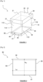
- top, bottom, front, “back”, “right” and “left” are defined in relation to a front view of the hive within the meaning of the [ Fig. 1 ], said front face comprising an opening for the passage of bees towards the inside or the outside of the hive.
- This definition, used here for explanatory purposes, cannot limit the scope of the present invention insofar as the opening for the passage of bees could be located elsewhere, for example on a side face of the hive.
- the hive 1 is of the Dadant hive type and comprises, in a simplified manner and for the sake of clarity, a body 10 (commonly called a hive body), a removable roof cover 20, a floor 30, a passage opening 40 for the bees, a plurality of body frames 50 and at least one radiating partition 60, in a non-limiting manner.
- the hive body 10 is parallelepipedal in shape and comprises four walls extending vertically: a front wall 11A, a rear wall 11B ([ Fig. 3 ]), opposite the front wall 11A, a left side wall 11C and a right side wall 11D.
- the side walls 11C and 11D each connect the front wall 11A to the rear wall 11B.
- the front wall 11A includes a lower edge.
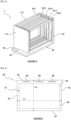
- the body 10 is capable of receiving removable body frames 50, an example of which is illustrated in the [ Fig.2 ], on which the bees will build their combs, and one or more removable radiating partitions 60.
- the body frames 50 and the radiating partitions 60 are arranged vertically between the left side wall 11C and the right side wall 11D.
- the front wall 11A and the rear wall 11B each comprise an inner face, oriented towards the inside of the hive 1.
- the hive 1 comprises, on the inner face of the front wall 11A and the rear wall 11B, recesses making it possible to receive the lateral edges of the body frames 50 and the radiating partitions 50 in order to block them in the hive body 10.
- the roof cover 20 is also parallelepipedal in shape and comprises four substantially vertical walls 21 and an upper plate 22 connecting said walls 21 so as to cover the walls 11A, 11B, 11C and 11D of the hive body 10, as illustrated in the [ Fig. 1 ].
- the floor 30 has the shape of a tray and comprises a rectangular bottom plate 31 on which are fixed two lateral edges 32 extending on either side over the entire length of the bottom plate 31.
- the length of the floor 30 is greater than the length of the side walls 11C, 11D of the body 10 of the hive 1 so as to form a so-called “flight” surface 33 allowing the bees to take off and land.
- the walls 11A, 11B, 11C and 11D of the body 10 rest on the lateral edges 32 of the floor 30 so as to form the passage opening 40 which extends between the bottom plate 31 and the lateral edges 32 of the floor 30 on the one hand and the lower edge of the front wall 11A of the body 10 on the other hand.
- the passage opening 40 allows the passage bees into or out of the hive 1.
- the walls 11A, 11B, 11C, 11D of the body 10 could comprise the passage opening 40 and a flight surface 33 extending perpendicularly from said wall 11A, 11B, 11C, 11D under said passage opening 40.
- the hive 1 according to the invention could comprise more than one passage opening 40 for the bees.
- Each body frame 50 is intended to be placed vertically in the hive 1 and comprises four thin borders, for example made of wood, including a lower border 51, an upper border 52, parallel to the lower border 51, and two lateral borders 53, parallel to each other and connecting the lower border 51 and the upper border 52.
- each border 51, 52, 53 designates the dimension of the borders along an axis normal to the plane in which each body frame 50 extends.
- the length L 50 of a body frame 50 designates the distance separating the lateral borders 53.
- the height H 50 of a body frame 50 designates the distance separating the lower border 51 and the upper border 52.
- the four edges 51, 52, 53 are connected by metal wires between which a sheet of embossed wax (not visible) is inserted, so that the bees build cells therein and then produce honey in the cells. Furthermore, the queen bee can also lay bee eggs in certain cells, in order to breed new bees.
- the body frames 50 can also have a reproductive function in addition to a honey production function. Furthermore, the body frames 50 can also have a pollen storage function, in order to feed the bee larvae.
- FIG. 3 With reference to the [ Fig. 3 ], there is shown a three-dimensional view of the floor 30, the front wall 11A, the rear wall 11B and the left side wall 11C of the body 10 of the hive 1 as well as a set of five body frames 50-1, 50-2, 50-3, 50-4, 50-5 mounted in the hive 1.
- the body frames 50-1, 50-2, 50-3, 50-4, 50-5 are arranged vertically and parallel to each other and to the left side wall 11C and the right side wall 11D (not shown in the [ Fig. 3 ]) inside hive 1.
- the length of the upper edge 52 is greater than the length L 50 , so that a portion of the upper edge 52 projects relative to each side edge 53 to block the body frame in the recesses of the inner faces of the front 11A and rear 10B walls of the hive body 10.
- Each radiant partition 60 serves to insulate the hive 1 from the cold by allowing a reduction in thermal exchanges and better conservation of heat inside the hive 1.
- the radiating partition 60 has a substantially rectangular shape and is configured to be inserted between the front wall 11A and the rear wall 11B of a body 10 of a beehive 1 in order to isolate the interior of said hive 1.
- the hive 1 comprises several radiating partitions 60, these radiating partitions 60 are preferably identical.
- the radiating partition 60 comprises a rigid single-piece panel 61 made of at least one insulating material and at least one of the two faces of which is covered at least in part with at least one layer made of a so-called “radiating” material, i.e. capable of reflecting and radiating a significant portion, at least 50%, of the thermal energy, in order to increase the effectiveness of the thermal insulation by more effectively retaining the heat inside the hive 1.
- a so-called “radiating” material i.e. capable of reflecting and radiating a significant portion, at least 50%, of the thermal energy
- the radiating partition 60 is delimited by an upper edge 62 extending horizontally, a lower edge 64, also extending horizontally while being parallel to the upper edge 62, two lateral edges 63 parallel to each other and connecting the upper edge 62 to the lower edge 64, and thus has two opposite faces 65.
- the radiating partition 60 has substantially the same length and width dimensions as those of the body frames 50.
- the length L 60 of each radiating partition 60 separating the lateral edges 63 is identical to the length L 50 of the body frames 50.
- the height H 60 of each radiating partition 60 separating the upper edge 62 and the lower edge 64 is equal to the height H 50 of the body frames 50.
- the radiating partition 60 is shaped so that the bees can move on either side of said radiating partition 60 by passing on the sides or under the radiating partition 60 but so that the queen, which is larger than the bees, cannot move under or on the sides of the radiating partition 60.
- each radiating partition 60 may be equal to or less than the thickness of the body frames 50. In particular, the thickness of each radiating partition 60 may be equal to half that of the body frames 50. In this case, for a hive 1 adapted to receive a given number of body frames 50, it is only necessary to remove one body frame 50 to replace it with two radiating partitions 60.
- the length of the upper edge 62 is greater than the length L 60 such that a portion of the upper edge 62 projects relative to each side edge 63 to hold each radiating partition 60 vertically in the same manner as the body frames 50.
- the radiating partitions 60 are mounted in the hive 1 in the manner of the body frames 50.
- the panel 61 may for example be made of solid wood, such as balsa or any other solid wood with high insulation capacity.
- the panel 61 may be made of plywood, for example of the CTB-X, CTB-H type or any other suitable type of plywood.
- the core of the panel 61 may be made of a polyurethane or polystyrene type material, in particular extruded polystyrene (for example of the Styrodur ® type), placed between two layers of wood veneer, for example glued.
- the panel 61 may for example be an OSB (Oriented Strand Board) oriented strand board.
- the panel 61 may for example be made of slatted wood.
- the layer of thermally radiating material is in the form of a sheet 68, fixed on one face 65 or on both faces 65 of the panel 61.
- the layer could be a layer of paint.
- Each sheet 68 is of dimensions substantially equal to those of the faces 65 of the panel 61, preferably covering at least 80% of the surface of each face 65 of the panel 61.
- a sheet 68 is fixed on each face 65 of the panel 61.
- Each radiating sheet 68 can for example be made of aluminum or any other suitable material, preferably whose thermal emissivity is less than or equal to 0.20, or even 0.10.
- unoxidized or polished aluminum with good radiation characteristics thermal emissivity of the order of 0.09 for unoxidized aluminum and of the order of 0.05 for polished aluminum
- polished (0.03) or oxidized (0.10) zinc polished copper (0.03) or polished brass (0.03 to 0.05)
- stainless steel 0.20
- polished steel 0.20
- unoxidized iron unoxidized iron
- the radiating partition 60 comprises at least one insertion member capable of receiving a tool for extracting the radiating partition.
- Each insertion member is in particular placed close to the upper edge 62 of said radiating partition 60.
- the insertion member is placed on at least one face 65 of the radiating partition 60.
- the insertion member is a recess, appearing in this example in the form of a groove 66 formed at the level of the upper part of at least one faces 65 of the radiating partition 60, for example less than 2 centimeters from the upper edge 62.
- the groove 66 extends horizontally on the face 65 of the radiating partition 60 in the position of use.
- the groove 66 is formed so that an extraction tool, such as a frame lifter, can be easily inserted into said groove 66 in order to extract the radiating partition 60 from the hive 1, in particular by leveraging on an adjacent frame.
- several grooves 66 are formed in each face 65 of the radiating partition 60.
- each face 65 has a plurality of coaxial grooves 66.
- the insertion member is placed on the upper edge 62.
- the insertion member may be in the form of a handle, a hook, a loop or the like, into which the extraction tool can be inserted.
- a frame lifter 80 cooperates with the insertion member, in other words the frame lifter 80 is partially inserted into the groove 66 by the beekeeper to extract the radiating partition 60 from the hive 1 by leverage, without however damaging the face 65 of the radiating partition 60 with the frame lifter 80.
- each radiating partition 60 comprises two through openings 67 formed near the lower edge 64.
- the radiating partition 60 could comprise a single through opening 67 or more than two through openings 67.
- the total surface area over which the single through opening 67 or the set of through openings 67 extends is preferably less than 20% of the surface area of the face 65 of the radiating partition 60.
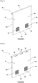
- figures 6 And 7 illustrate a second embodiment of the radiating partition 60 according to the invention.
- the [ Fig.8 ] illustrates a third embodiment of the radiating partition 60 according to the invention.
- the radiating partition 60 comprises a grid 70 mounted in each through opening 67 of the panel 61.
- the grid 70 comprises a set of vertical and horizontal bars spaced so that the worker bees can pass through the grid 70 but the queen bee, whose size is larger than the other bees, cannot pass through the grid 70.
- only the bees and not the queen can easily move from one side to the other of each radiating partition 60, in particular in order to produce honey on the entire surface of the embossed wax of the first frame 50-1 and the last frame 50-5 ( figures 3 And 9 ) and not just on the edges.
- only bees and not the queen can access the first 50-1 frame and the last 50-5 frame.
- the queen cannot lay bee eggs in the cells of the first 50-1 frame and the last 50-5 frame.
- the first 50-1 production frame and the last 50-5 production frame production thus have the sole function of producing honey, over their entire surface thanks to the grid(s) 70.
- the grids 70 are not visible on the [ Fig.6 ] for reasons of clarity, in order to clearly visualize the through openings 67.
- a third embodiment of the radiating partition 60 is shown in which the panel 61 comprises two through openings 67, in each of which a grid 70 is mounted, and three grooves 66.
- the hive 1 comprises a first radiating partition 60-1 and a second radiating partition 60-2.
- the first radiating partition 60-1 is placed in the hive 1 between a first body frame 50-1, adjacent to the left side wall 11C.
- the second radiating partition 60-2 is placed between a fourth body frame 50-4 and a fifth body frame 50-5, adjacent to the right side wall 11D.
- the bees are insulated from the cold between the first radiating partition 60-1 and the second radiating partition 60-2, in particular because the radiating material makes it possible to store heat in the center of the body 10 of the hive 1, in particular the heat produced by the bees being reflected by the radiating partitions 60-1, 60-2.
- the hive 1 comprises a control module 85 and two radiant heating partitions 60-C.
- the two radiant heating partitions 60-C are mounted in the same location as the first radiant partition 60-1 and the second radiant partition 60-2 of the previous embodiment, i.e., at the second and penultimate position in the body frame assembly 50.
- Each 60-C radiant heating partition includes several heating elements.
- the heating elements are in the form of heating resistors R1, R2, R3, R4.
- each radiant heating partition 60-C comprises in this non-limiting example four resistors R1, R2, R3, R4 extending longitudinally mounted on one of the faces of said radiant heating partition 60-C.
- Two resistors R1 and R2 are each arranged extending respectively along the left lateral edge 63G and the right lateral edge 63D of the panel 61.
- a resistor R3 is arranged extending along the lower edge 64 of the panel 61 and an R4 is arranged in the upper part of the panel extending transversely parallel to the upper edge 62 of the panel, under the three grooves 66.
- Resistors R1, R2, R3, R4 are mounted on the faces that are facing the center of hive 1 in order to heat the body frames 50 which are placed between the two radiant heating partitions 60-C.
- the control module 90 may be internal or external to the hive 1.
- the control module 90 may be mounted in or on the hive 1 or may be placed outside the hive 1.
- the control module 90 is electrically powered by an internal or external power source 100.
- the control module 90 receives temperature measurements from temperature probes (not shown for clarity) placed inside the hive 1 and to electronically regulate the temperature inside the hive 1 between a floor temperature and a ceiling temperature (thermostat function) from the temperature measurements received from the probes.
- the control module 90 carries out the temperature regulation inside the hive 1, for example micro-cuts and/or by controlling the operation of only part of the heating resistors R1, R2, R3, R4 of the partition(s) 60-C of the hive 1.
- the floor temperature can be chosen so that the bees do not suffer from the cold, especially in winter.
- the floor temperature is greater than or equal to 20°C, preferably 30°C, more preferably 40°C.
- the floor temperature can be chosen so as to kill the "varroa destructor", which is a species of mite parasitic on adult bees, larvae and pupae.
- the floor temperature should preferably be greater than or equal to 42°C.
- the ceiling temperature is chosen so as to avoid overheating of hive 1 which could kill the bee larvae, for example above an ambient temperature of 44°C.
- the ceiling temperature can be chosen so that the internal ambient temperature of hive 1 does not reach the overheating temperature, i.e. the ceiling temperature must be lower than the overheating temperature and chosen so that the heating inertia of the resistors R1, R2, R3, R4 (i.e. the heat they continue to produce when their electricity supply is cut off) does not allow the overheating temperature to be reached.
- the ceiling temperature can be 43° to ensure that the internal temperature does not reach 44°C by inertia.
- Varroa treatment can be carried out for example for 2 to 3 hours to ensure that it is destroyed.
- the floor temperature and ceiling temperature can be set by a user.
- this setting can be done directly in the control module 90 or remotely, for example via an application and a link wireless communication, for example Wifi, Bluetooth ® , 2G/3G/4G/5G, in order to transmit the setting data to the control module 90 for adjustment.
- a link wireless communication for example Wifi, Bluetooth ® , 2G/3G/4G/5G, in order to transmit the setting data to the control module 90 for adjustment.
- the current is supplied by an electrical power source 100 capable of generating an electric current and supplying a voltage to the control module 90.
- This electrical power source 100 may be a battery embedded in the hive 1, for example inside the hive 1 or mounted on one of the walls of the hive 1, or may be external to the hive 1, for example in the form of a diesel generator or external electric generator. In the latter case, the external electrical power source 100 may be connected to the thermostat 90 via a cable 110 and connected to a connector (not shown) mounted on one of the walls of the hive 1 and electrically connected to the control module 90.
- the two radiant heating partitions 60-C are electrically connected to the control module 90 in order to receive the current generated by the electrical power source 100 when the measured temperature is lower than a predetermined floor temperature and thus supply current to the resistors R1, R2, R3, R4 to heat the interior of the hive 1.
- Each resistor R1, R2, R3, R4 is connected to the control module 90 by a pair of internal cables 91.
- the two radiant heating partitions 60-C generate heat inside the hive 1 by being electrically powered by the resistors integrated on the faces of the radiant heating partitions 60-C in order to heat the interior of the hive 1.
- the radiant partition 60 therefore makes it possible in a simple, inexpensive, reliable and effective manner to insulate the hive 1 to protect the bees from the cold, in particular when it comprises one or more heating elements. It will be noted that any variant different from the embodiment described above but having the same function of radiant partition with easy and rapid extraction is envisaged by the present document.
- the shape, dimensions and elements of the hive 1, the body 10 of the hive 1, the cover 20, the floor 30, the body frames 50 and the radiant partitions 60 are in no way limiting of the scope of the present invention.
Landscapes
- Life Sciences & Earth Sciences (AREA)
- Environmental Sciences (AREA)
- Animal Husbandry (AREA)
- Biodiversity & Conservation Biology (AREA)
- Building Environments (AREA)
- Housing For Livestock And Birds (AREA)
Claims (15)
- Strahlende Trennwand (60) für einen Bienenstock (1), wobei der Bienenstock (1) einen Boden (30), eine Vorderwand (11A), zwei Seitenwände (11C), eine Rückwand (11B) und einen abnehmbaren Dachdeckel (20) umfasst, dadurch gekennzeichnet, dass die strahlende Trennwand (60) eine starre einteilige Platte (61) umfasst, die aus mindestens einem Isoliermaterial hergestellt ist, von der mindestens eine der beiden Seiten (65) mindestens teilweise mit mindestens einer Schicht aus einem strahlenden Material (68) bedeckt ist, wobei die strahlende Trennwand (60) ausgelegt ist, um zwischen der Vorderwand (11A) und der Rückwand (11B) des Bienenstocks (1) eingesetzt zu sein, um das Innere des Bienenstocks (1) zu isolieren.
- Strahlende Trennwand (60) nach Anspruch 1, wobei die Schicht aus strahlendem Material (68) eine thermische Emissivität unter 0,2 aufweist.
- Strahlende Trennwand (60) nach vorhergehendem Anspruch, wobei die Schicht aus strahlendem Material (68) eine thermische Emissivität unter 0,1 aufweist.
- Strahlende Trennwand (60) nach einem der vorhergehenden Ansprüche, wobei die Platte (61) aus Massivholz, Sperrholz, Grobspanplatten oder Lattenholz hergestellt ist.
- Strahlende Trennwand (60) nach einem der vorhergehenden Ansprüche, umfassend mindestens ein Einfügeelement (66), das imstande ist, ein Werkzeug (80) zum Entfernen der strahlenden Trennwand (60) aus einem Bienenstock (1) aufzunehmen.
- Strahlende Trennwand (60) nach vorhergehendem Anspruch, wobei die Platte (61) durch eine Oberkante (62), eine Unterkante (64), zwei Seitenkanten (63) und zwei Seiten (65) begrenzt ist, wobei jede der Seiten die Oberkante (62), die Unterkante (64) und die Seitenkanten (63) verbindet, das Einfügeelement in Form einer Nut (66) ausgebildet ist, die im oberen Bereich von mindestens einer der beiden Seiten (65) der strahlenden Trennwand (60) ausgebildet ist.
- Strahlende Trennwand (60) nach einem der vorhergehenden Ansprüche, wobei die strahlende Trennwand (60) massiv ist.
- Strahlende Trennwand (60) nach einem der Ansprüche 1 bis 6, wobei die strahlende Trennwand (60) mindestens eine Durchgangsöffnung (67) begrenzt, in der ein Gitter (70) angebracht ist, das geeignet ist, die Bienenkönigin (1) daran zu hindern, die Öffnung (67) zu durchqueren, während es den Arbeitsbienen erlaubt, sie zu durchqueren.
- Strahlende Trennwand (60) nach vorhergehendem Anspruch, umfassend eine Unterkante (64) und wobei die Durchgangsöffnung (67) in der Nähe der Unterkante (64) angeordnet ist.
- Strahlende Trennwand (60) nach einem der vorhergehenden Ansprüche, bezeichnet als "heizende strahlende Trennwand" (60-C), umfassend mindestens ein integriertes Heizelement.
- Heizende strahlende Trennwand (60-C) nach vorhergehendem Anspruch, wobei das mindestens eine integrierte Heizelement vom Typ Widerstand ist.
- Heizende strahlende Trennwand (60-C) nach vorhergehendem Anspruch, umfassend vier sich längs erstreckende Widerstände, die auf einer der Seiten der heizenden strahlenden Trennwand (60-C) angebracht sind, von denen zwei angeordnet sind, indem sie sich jeweils entlang einer Seitenkante der Platte (61) verlaufend erstrecken, eine angeordnet ist, indem sie sich entlang der Unterkante der Platte (61) verlaufend erstreckt und eine im oberen Teil der Platte angeordnet ist, indem sie sich quer verlaufend erstreckt.
- Bienenstock (1), umfassend einen Boden (30), eine Vorderwand (11A), zwei Seitenwände (11C), eine Rückwand (11B), einen abnehmbaren Dachdeckel (20), mindestens einem Körperrahmen (50), wobei jeder Körperrahmen (50) die Form eines vom Bienenstock (1) lösbaren Gestells aufweist, dadurch gekennzeichnet, dass das Gestell vier dünne Ränder aufweist, die durch Metalldrähte verbunden sind, zwischen denen eine geprägte Wachsfolie eingefügt ist, die es den Bienen ermöglicht, Honig zu produzieren, wobei der Bienenstock (1) ferner mindestens eine strahlende Trennwand (60) nach einem der vorhergehenden Ansprüche umfasst.
- Bienenstock (1) nach vorhergehendem Anspruch, umfassend mindestens eine heizende strahlende Trennwand (60-C) nach einem der Ansprüche 10 bis 12.
- Bienenstock (1) nach vorhergehendem Anspruch, umfassend ferner mindestens eine im Inneren des Bienenstocks (1) angebrachte Temperaturmesssonde und ein Steuermodul (90), das im Inneren oder außerhalb des Bienenstocks (1) angebracht ist, wobei es elektrisch mit dem mindestens ein Heizelement (R1, R2, R3, R4) der heizenden strahlenden Trennwand (60-C) verbunden und ausgelegt ist, um, wenn das Steuermodul (90) mit Strom versorgt wird, die Temperaturmessungen der mindestens einen Sonde zu empfangen und die Temperatur im Inneren des Bienenstocks zwischen einer Mindesttemperatur und einer Höchsttemperatur zu regeln.
Applications Claiming Priority (2)
| Application Number | Priority Date | Filing Date | Title |
|---|---|---|---|
| FR2100840A FR3119080B1 (fr) | 2021-01-28 | 2021-01-28 | Partition rayonnante pour ruche |
| PCT/EP2022/052136 WO2022162194A1 (fr) | 2021-01-28 | 2022-01-28 | Partition pour ruche |
Publications (3)
| Publication Number | Publication Date |
|---|---|
| EP4284162A1 EP4284162A1 (de) | 2023-12-06 |
| EP4284162C0 EP4284162C0 (de) | 2025-05-07 |
| EP4284162B1 true EP4284162B1 (de) | 2025-05-07 |
Family
ID=74871669
Family Applications (1)
| Application Number | Title | Priority Date | Filing Date |
|---|---|---|---|
| EP22702002.1A Active EP4284162B1 (de) | 2021-01-28 | 2022-01-28 | Trennwand für einen bienenstock |
Country Status (6)
| Country | Link |
|---|---|
| US (1) | US12538903B2 (de) |
| EP (1) | EP4284162B1 (de) |
| CA (1) | CA3205273A1 (de) |
| ES (1) | ES3038948T3 (de) |
| FR (1) | FR3119080B1 (de) |
| WO (1) | WO2022162194A1 (de) |
Citations (3)
| Publication number | Priority date | Publication date | Assignee | Title |
|---|---|---|---|---|
| WO2010098853A1 (en) * | 2009-02-25 | 2010-09-02 | Mcneil Michael B | Ventilation, moisture removal and heat management in a beehive |
| WO2018165051A1 (en) * | 2017-03-06 | 2018-09-13 | Butzloff Peter Robert | Apparatus, methods, and medicaments for treatment of insect pollinators |
| FR3069412A1 (fr) * | 2017-07-27 | 2019-02-01 | Smurfit Kappa France | Dispositif de partition isolante pour une ruche a elements de panneaux amovibles. |
Family Cites Families (6)
| Publication number | Priority date | Publication date | Assignee | Title |
|---|---|---|---|---|
| CZ2012775A3 (cs) * | 2012-11-12 | 2014-07-23 | Roman Linhart | Způsob tepelného ošetření včelstev a zařízení k provádění tohoto způsobu |
| WO2017210410A1 (en) * | 2016-06-01 | 2017-12-07 | Bee Hive Thermal Industries, Llc | Heater-equipped man-made beehive, and method for controlling invasive pests in a man-made beehive |
| US11375697B2 (en) * | 2017-04-12 | 2022-07-05 | Alessandro GAMBERONI | Rational hive structure |
| US20190364853A1 (en) * | 2018-06-04 | 2019-12-05 | Steven Allen Voisin | Method and System for Protecting Apiaries by Means of Thermal and Moisture Membranes |
| AT522970B1 (de) * | 2019-10-17 | 2021-04-15 | Youbee Gmbh | Mittelwand für einen Bienenstock zur hyperthermischen Varroadezimierung |
| CA3113364A1 (en) * | 2021-03-26 | 2022-09-26 | Riverview Ranch Ltd. | Bee shelter |
-
2021
- 2021-01-28 FR FR2100840A patent/FR3119080B1/fr active Active
-
2022
- 2022-01-28 ES ES22702002T patent/ES3038948T3/es active Active
- 2022-01-28 EP EP22702002.1A patent/EP4284162B1/de active Active
- 2022-01-28 CA CA3205273A patent/CA3205273A1/fr active Pending
- 2022-01-28 WO PCT/EP2022/052136 patent/WO2022162194A1/fr not_active Ceased
- 2022-01-28 US US18/262,952 patent/US12538903B2/en active Active
Patent Citations (3)
| Publication number | Priority date | Publication date | Assignee | Title |
|---|---|---|---|---|
| WO2010098853A1 (en) * | 2009-02-25 | 2010-09-02 | Mcneil Michael B | Ventilation, moisture removal and heat management in a beehive |
| WO2018165051A1 (en) * | 2017-03-06 | 2018-09-13 | Butzloff Peter Robert | Apparatus, methods, and medicaments for treatment of insect pollinators |
| FR3069412A1 (fr) * | 2017-07-27 | 2019-02-01 | Smurfit Kappa France | Dispositif de partition isolante pour une ruche a elements de panneaux amovibles. |
Also Published As
| Publication number | Publication date |
|---|---|
| WO2022162194A1 (fr) | 2022-08-04 |
| CA3205273A1 (fr) | 2022-08-04 |
| US12538903B2 (en) | 2026-02-03 |
| EP4284162A1 (de) | 2023-12-06 |
| FR3119080B1 (fr) | 2023-01-20 |
| US20250151703A1 (en) | 2025-05-15 |
| ES3038948T3 (en) | 2025-10-16 |
| EP4284162C0 (de) | 2025-05-07 |
| FR3119080A1 (fr) | 2022-07-29 |
Similar Documents
| Publication | Publication Date | Title |
|---|---|---|
| JP7619765B2 (ja) | 電池パック、処理システムおよび電池パックの製造方法 | |
| US11122781B2 (en) | Heater-equipped man-made beehive, and method for controlling invasive pests in a man-made beehive | |
| JP7595426B2 (ja) | 電池パック、処理システムおよび電池パックの製造方法 | |
| EP4284162B1 (de) | Trennwand für einen bienenstock | |
| EP0191704A1 (de) | Imkerkassette zur Bildung einer Bienenkolonie, zum Königinnentausch bei vollem Stock sowie zum teilweisen Blockieren der Eiablage | |
| EP2204089A1 (de) | Wabenrahmen für einen Bienstock | |
| WO2020025899A1 (fr) | Ensemble automatise de ruches | |
| EP3903363B1 (de) | Elektrisches batteriemodul und batterie mit mindestens einem solchen modul | |
| FR3027184B1 (fr) | Coeur de chauffe electrique a double isolation pour appareil de chauffage, procede de realisation du coeur de chauffe, et appareil de chauffage incluant de tels coeurs de chauffe | |
| FR3069564A1 (fr) | Abri stationnaire transportable, pour le stockage de modules de stockage d'energie electrique | |
| WO2005018313A1 (fr) | Dispositif pour l’elevage d’abeilles et la lutte contre la varroa jacobsoni | |
| KR101881946B1 (ko) | 벌꿀 채집이 용이한 벌통 | |
| BE1028175B1 (fr) | Cadre pour ruche | |
| FR3073606B1 (fr) | Appareil de chauffage integrant une batterie implantee dans le flux d’air frais entrant | |
| FR2970600A1 (fr) | Dispositif de reception d'une pluralite de batteries. | |
| FR3109492A1 (fr) | Dispositif autonome d’extraction de miel à partir d’un réceptacle comprenant des rayons de miel | |
| FR2595909A1 (fr) | Ruche divisible pour une ou plusieurs colonies d'abeilles, et a elements amovibles, emboitables et standardises | |
| FR3107424A1 (fr) | Caisson avec compartiment amovible pour ruche | |
| FR2943500A1 (fr) | Dispositif polyvalent pour nourrir abondamment les abeilles en toutes circonstances,verifier rapidement,sans manipulation leur consommation les proteger des conditions climatique. | |
| WO2020065170A1 (fr) | Boitier d'interface électronique d'un dispositif de chauffage électrique | |
| FR3164601A1 (fr) | Ruche en matière plastique et kit plancher | |
| FR3146045A1 (fr) | Support porte-cadres de ruche | |
| KR200379560Y1 (ko) | 양봉용 소상밑판 | |
| KR200378380Y1 (ko) | 양봉용 소상 | |
| KR200379934Y1 (ko) | 양봉용 소상 |
Legal Events
| Date | Code | Title | Description |
|---|---|---|---|
| STAA | Information on the status of an ep patent application or granted ep patent |
Free format text: STATUS: UNKNOWN |
|
| STAA | Information on the status of an ep patent application or granted ep patent |
Free format text: STATUS: THE INTERNATIONAL PUBLICATION HAS BEEN MADE |
|
| PUAI | Public reference made under article 153(3) epc to a published international application that has entered the european phase |
Free format text: ORIGINAL CODE: 0009012 |
|
| STAA | Information on the status of an ep patent application or granted ep patent |
Free format text: STATUS: REQUEST FOR EXAMINATION WAS MADE |
|
| 17P | Request for examination filed |
Effective date: 20230720 |
|
| AK | Designated contracting states |
Kind code of ref document: A1 Designated state(s): AL AT BE BG CH CY CZ DE DK EE ES FI FR GB GR HR HU IE IS IT LI LT LU LV MC MK MT NL NO PL PT RO RS SE SI SK SM TR |
|
| DAV | Request for validation of the european patent (deleted) | ||
| DAX | Request for extension of the european patent (deleted) | ||
| GRAP | Despatch of communication of intention to grant a patent |
Free format text: ORIGINAL CODE: EPIDOSNIGR1 |
|
| STAA | Information on the status of an ep patent application or granted ep patent |
Free format text: STATUS: GRANT OF PATENT IS INTENDED |
|
| INTG | Intention to grant announced |
Effective date: 20241127 |
|
| GRAS | Grant fee paid |
Free format text: ORIGINAL CODE: EPIDOSNIGR3 |
|
| GRAA | (expected) grant |
Free format text: ORIGINAL CODE: 0009210 |
|
| STAA | Information on the status of an ep patent application or granted ep patent |
Free format text: STATUS: THE PATENT HAS BEEN GRANTED |
|
| AK | Designated contracting states |
Kind code of ref document: B1 Designated state(s): AL AT BE BG CH CY CZ DE DK EE ES FI FR GB GR HR HU IE IS IT LI LT LU LV MC MK MT NL NO PL PT RO RS SE SI SK SM TR |
|
| REG | Reference to a national code |
Ref country code: GB Ref legal event code: FG4D Free format text: NOT ENGLISH |
|
| REG | Reference to a national code |
Ref country code: CH Ref legal event code: EP |
|
| REG | Reference to a national code |
Ref country code: DE Ref legal event code: R096 Ref document number: 602022014226 Country of ref document: DE |
|
| REG | Reference to a national code |
Ref country code: IE Ref legal event code: FG4D Free format text: LANGUAGE OF EP DOCUMENT: FRENCH |
|
| U01 | Request for unitary effect filed |
Effective date: 20250528 |
|
| U07 | Unitary effect registered |
Designated state(s): AT BE BG DE DK EE FI FR IT LT LU LV MT NL PT RO SE SI Effective date: 20250606 |
|
| U1N | Appointed representative for the unitary patent procedure changed after the registration of the unitary effect |
Representative=s name: BORNIER, RAYNALD; FR |
|
| PG25 | Lapsed in a contracting state [announced via postgrant information from national office to epo] |
Ref country code: NO Free format text: LAPSE BECAUSE OF FAILURE TO SUBMIT A TRANSLATION OF THE DESCRIPTION OR TO PAY THE FEE WITHIN THE PRESCRIBED TIME-LIMIT Effective date: 20250807 Ref country code: GR Free format text: LAPSE BECAUSE OF FAILURE TO SUBMIT A TRANSLATION OF THE DESCRIPTION OR TO PAY THE FEE WITHIN THE PRESCRIBED TIME-LIMIT Effective date: 20250808 |
|
| PG25 | Lapsed in a contracting state [announced via postgrant information from national office to epo] |
Ref country code: PL Free format text: LAPSE BECAUSE OF FAILURE TO SUBMIT A TRANSLATION OF THE DESCRIPTION OR TO PAY THE FEE WITHIN THE PRESCRIBED TIME-LIMIT Effective date: 20250507 |
|
| REG | Reference to a national code |
Ref country code: ES Ref legal event code: FG2A Ref document number: 3038948 Country of ref document: ES Kind code of ref document: T3 Effective date: 20251016 |
|
| PG25 | Lapsed in a contracting state [announced via postgrant information from national office to epo] |
Ref country code: HR Free format text: LAPSE BECAUSE OF FAILURE TO SUBMIT A TRANSLATION OF THE DESCRIPTION OR TO PAY THE FEE WITHIN THE PRESCRIBED TIME-LIMIT Effective date: 20250507 |
|
| PG25 | Lapsed in a contracting state [announced via postgrant information from national office to epo] |
Ref country code: RS Free format text: LAPSE BECAUSE OF FAILURE TO SUBMIT A TRANSLATION OF THE DESCRIPTION OR TO PAY THE FEE WITHIN THE PRESCRIBED TIME-LIMIT Effective date: 20250807 |
|
| PG25 | Lapsed in a contracting state [announced via postgrant information from national office to epo] |
Ref country code: IS Free format text: LAPSE BECAUSE OF FAILURE TO SUBMIT A TRANSLATION OF THE DESCRIPTION OR TO PAY THE FEE WITHIN THE PRESCRIBED TIME-LIMIT Effective date: 20250907 |
|
| PG25 | Lapsed in a contracting state [announced via postgrant information from national office to epo] |
Ref country code: SM Free format text: LAPSE BECAUSE OF FAILURE TO SUBMIT A TRANSLATION OF THE DESCRIPTION OR TO PAY THE FEE WITHIN THE PRESCRIBED TIME-LIMIT Effective date: 20250507 |
|
| PG25 | Lapsed in a contracting state [announced via postgrant information from national office to epo] |
Ref country code: CZ Free format text: LAPSE BECAUSE OF FAILURE TO SUBMIT A TRANSLATION OF THE DESCRIPTION OR TO PAY THE FEE WITHIN THE PRESCRIBED TIME-LIMIT Effective date: 20250507 |
|
| PG25 | Lapsed in a contracting state [announced via postgrant information from national office to epo] |
Ref country code: SK Free format text: LAPSE BECAUSE OF FAILURE TO SUBMIT A TRANSLATION OF THE DESCRIPTION OR TO PAY THE FEE WITHIN THE PRESCRIBED TIME-LIMIT Effective date: 20250507 |
|
| U20 | Renewal fee for the european patent with unitary effect paid |
Year of fee payment: 5 Effective date: 20251222 |
|
| REG | Reference to a national code |
Ref country code: CH Ref legal event code: U11 Free format text: ST27 STATUS EVENT CODE: U-0-0-U10-U11 (AS PROVIDED BY THE NATIONAL OFFICE) Effective date: 20260201 |
|
| PLBE | No opposition filed within time limit |
Free format text: ORIGINAL CODE: 0009261 |
|
| STAA | Information on the status of an ep patent application or granted ep patent |
Free format text: STATUS: NO OPPOSITION FILED WITHIN TIME LIMIT |
|
| REG | Reference to a national code |
Ref country code: CH Ref legal event code: L10 Free format text: ST27 STATUS EVENT CODE: U-0-0-L10-L00 (AS PROVIDED BY THE NATIONAL OFFICE) Effective date: 20260318 |
|
| PGFP | Annual fee paid to national office [announced via postgrant information from national office to epo] |
Ref country code: ES Payment date: 20260217 Year of fee payment: 5 |
|
| 26N | No opposition filed |
Effective date: 20260210 |
|
| PGFP | Annual fee paid to national office [announced via postgrant information from national office to epo] |
Ref country code: TR Payment date: 20260126 Year of fee payment: 5 |
|
| PGFP | Annual fee paid to national office [announced via postgrant information from national office to epo] |
Ref country code: CH Payment date: 20260201 Year of fee payment: 5 |