EP4283757A1 - System zur schätzung der restkapazität eines energiespeichersystems (ess) und verfahren dafür - Google Patents
System zur schätzung der restkapazität eines energiespeichersystems (ess) und verfahren dafür Download PDFInfo
- Publication number
- EP4283757A1 EP4283757A1 EP22878898.0A EP22878898A EP4283757A1 EP 4283757 A1 EP4283757 A1 EP 4283757A1 EP 22878898 A EP22878898 A EP 22878898A EP 4283757 A1 EP4283757 A1 EP 4283757A1
- Authority
- EP
- European Patent Office
- Prior art keywords
- ess
- dod
- rate
- residual capacity
- decay rate
- Prior art date
- Legal status (The legal status is an assumption and is not a legal conclusion. Google has not performed a legal analysis and makes no representation as to the accuracy of the status listed.)
- Pending
Links
Images


Classifications
-
- H—ELECTRICITY
- H01—ELECTRIC ELEMENTS
- H01M—PROCESSES OR MEANS, e.g. BATTERIES, FOR THE DIRECT CONVERSION OF CHEMICAL ENERGY INTO ELECTRICAL ENERGY
- H01M10/00—Secondary cells; Manufacture thereof
- H01M10/42—Methods or arrangements for servicing or maintenance of secondary cells or secondary half-cells
- H01M10/425—Structural combination with electronic components, e.g. electronic circuits integrated to the outside of the casing
-
- G—PHYSICS
- G01—MEASURING; TESTING
- G01R—MEASURING ELECTRIC VARIABLES; MEASURING MAGNETIC VARIABLES
- G01R31/00—Arrangements for testing electric properties; Arrangements for locating electric faults; Arrangements for electrical testing characterised by what is being tested not provided for elsewhere
- G01R31/36—Arrangements for testing, measuring or monitoring the electrical condition of accumulators or electric batteries, e.g. capacity or state of charge [SoC]
- G01R31/3644—Constructional arrangements
- G01R31/3648—Constructional arrangements comprising digital calculation means, e.g. for performing an algorithm
-
- G—PHYSICS
- G01—MEASURING; TESTING
- G01R—MEASURING ELECTRIC VARIABLES; MEASURING MAGNETIC VARIABLES
- G01R31/00—Arrangements for testing electric properties; Arrangements for locating electric faults; Arrangements for electrical testing characterised by what is being tested not provided for elsewhere
- G01R31/36—Arrangements for testing, measuring or monitoring the electrical condition of accumulators or electric batteries, e.g. capacity or state of charge [SoC]
- G01R31/382—Arrangements for monitoring battery or accumulator variables, e.g. SoC
-
- G—PHYSICS
- G01—MEASURING; TESTING
- G01R—MEASURING ELECTRIC VARIABLES; MEASURING MAGNETIC VARIABLES
- G01R31/00—Arrangements for testing electric properties; Arrangements for locating electric faults; Arrangements for electrical testing characterised by what is being tested not provided for elsewhere
- G01R31/36—Arrangements for testing, measuring or monitoring the electrical condition of accumulators or electric batteries, e.g. capacity or state of charge [SoC]
- G01R31/385—Arrangements for measuring battery or accumulator variables
- G01R31/387—Determining ampere-hour charge capacity or SoC
-
- G—PHYSICS
- G01—MEASURING; TESTING
- G01R—MEASURING ELECTRIC VARIABLES; MEASURING MAGNETIC VARIABLES
- G01R31/00—Arrangements for testing electric properties; Arrangements for locating electric faults; Arrangements for electrical testing characterised by what is being tested not provided for elsewhere
- G01R31/36—Arrangements for testing, measuring or monitoring the electrical condition of accumulators or electric batteries, e.g. capacity or state of charge [SoC]
- G01R31/392—Determining battery ageing or deterioration, e.g. state of health
-
- G—PHYSICS
- G01—MEASURING; TESTING
- G01R—MEASURING ELECTRIC VARIABLES; MEASURING MAGNETIC VARIABLES
- G01R31/00—Arrangements for testing electric properties; Arrangements for locating electric faults; Arrangements for electrical testing characterised by what is being tested not provided for elsewhere
- G01R31/36—Arrangements for testing, measuring or monitoring the electrical condition of accumulators or electric batteries, e.g. capacity or state of charge [SoC]
- G01R31/396—Acquisition or processing of data for testing or for monitoring individual cells or groups of cells within a battery
-
- H—ELECTRICITY
- H01—ELECTRIC ELEMENTS
- H01M—PROCESSES OR MEANS, e.g. BATTERIES, FOR THE DIRECT CONVERSION OF CHEMICAL ENERGY INTO ELECTRICAL ENERGY
- H01M10/00—Secondary cells; Manufacture thereof
- H01M10/42—Methods or arrangements for servicing or maintenance of secondary cells or secondary half-cells
- H01M10/4207—Methods or arrangements for servicing or maintenance of secondary cells or secondary half-cells for several batteries or cells simultaneously or sequentially
-
- H—ELECTRICITY
- H01—ELECTRIC ELEMENTS
- H01M—PROCESSES OR MEANS, e.g. BATTERIES, FOR THE DIRECT CONVERSION OF CHEMICAL ENERGY INTO ELECTRICAL ENERGY
- H01M10/00—Secondary cells; Manufacture thereof
- H01M10/42—Methods or arrangements for servicing or maintenance of secondary cells or secondary half-cells
- H01M10/44—Methods for charging or discharging
- H01M10/441—Methods for charging or discharging for several batteries or cells simultaneously or sequentially
-
- H—ELECTRICITY
- H01—ELECTRIC ELEMENTS
- H01M—PROCESSES OR MEANS, e.g. BATTERIES, FOR THE DIRECT CONVERSION OF CHEMICAL ENERGY INTO ELECTRICAL ENERGY
- H01M10/00—Secondary cells; Manufacture thereof
- H01M10/42—Methods or arrangements for servicing or maintenance of secondary cells or secondary half-cells
- H01M10/44—Methods for charging or discharging
- H01M10/443—Methods for charging or discharging in response to temperature
-
- H—ELECTRICITY
- H01—ELECTRIC ELEMENTS
- H01M—PROCESSES OR MEANS, e.g. BATTERIES, FOR THE DIRECT CONVERSION OF CHEMICAL ENERGY INTO ELECTRICAL ENERGY
- H01M10/00—Secondary cells; Manufacture thereof
- H01M10/42—Methods or arrangements for servicing or maintenance of secondary cells or secondary half-cells
- H01M10/48—Accumulators combined with arrangements for measuring, testing or indicating the condition of cells, e.g. the level or density of the electrolyte
- H01M10/482—Accumulators combined with arrangements for measuring, testing or indicating the condition of cells, e.g. the level or density of the electrolyte for several batteries or cells simultaneously or sequentially
-
- H—ELECTRICITY
- H01—ELECTRIC ELEMENTS
- H01M—PROCESSES OR MEANS, e.g. BATTERIES, FOR THE DIRECT CONVERSION OF CHEMICAL ENERGY INTO ELECTRICAL ENERGY
- H01M50/00—Constructional details or processes of manufacture of the non-active parts of electrochemical cells other than fuel cells, e.g. hybrid cells
- H01M50/20—Mountings; Secondary casings or frames; Racks, modules or packs; Suspension devices; Shock absorbers; Transport or carrying devices; Holders
- H01M50/251—Mountings; Secondary casings or frames; Racks, modules or packs; Suspension devices; Shock absorbers; Transport or carrying devices; Holders specially adapted for stationary devices, e.g. power plant buffering or backup power supplies
-
- H—ELECTRICITY
- H02—GENERATION; CONVERSION OR DISTRIBUTION OF ELECTRIC POWER
- H02J—ELECTRIC POWER NETWORKS; CIRCUIT ARRANGEMENTS OR SYSTEMS FOR SUPPLYING OR DISTRIBUTING ELECTRIC POWER; SYSTEMS FOR STORING ELECTRIC ENERGY
- H02J7/00—Circuit arrangements for charging or discharging batteries or for supplying loads from batteries
- H02J7/80—Circuit arrangements for charging or discharging batteries or for supplying loads from batteries including monitoring or indicating arrangements
- H02J7/82—Control of state of charge [SOC]
-
- G—PHYSICS
- G01—MEASURING; TESTING
- G01R—MEASURING ELECTRIC VARIABLES; MEASURING MAGNETIC VARIABLES
- G01R31/00—Arrangements for testing electric properties; Arrangements for locating electric faults; Arrangements for electrical testing characterised by what is being tested not provided for elsewhere
- G01R31/36—Arrangements for testing, measuring or monitoring the electrical condition of accumulators or electric batteries, e.g. capacity or state of charge [SoC]
- G01R31/374—Arrangements for testing, measuring or monitoring the electrical condition of accumulators or electric batteries, e.g. capacity or state of charge [SoC] with means for correcting the measurement for temperature or ageing
-
- H—ELECTRICITY
- H01—ELECTRIC ELEMENTS
- H01M—PROCESSES OR MEANS, e.g. BATTERIES, FOR THE DIRECT CONVERSION OF CHEMICAL ENERGY INTO ELECTRICAL ENERGY
- H01M10/00—Secondary cells; Manufacture thereof
- H01M10/42—Methods or arrangements for servicing or maintenance of secondary cells or secondary half-cells
- H01M10/425—Structural combination with electronic components, e.g. electronic circuits integrated to the outside of the casing
- H01M2010/4271—Battery management systems including electronic circuits, e.g. control of current or voltage to keep battery in healthy state, cell balancing
-
- H—ELECTRICITY
- H01—ELECTRIC ELEMENTS
- H01M—PROCESSES OR MEANS, e.g. BATTERIES, FOR THE DIRECT CONVERSION OF CHEMICAL ENERGY INTO ELECTRICAL ENERGY
- H01M2220/00—Batteries for particular applications
- H01M2220/10—Batteries in stationary systems, e.g. emergency power source in plant
-
- Y—GENERAL TAGGING OF NEW TECHNOLOGICAL DEVELOPMENTS; GENERAL TAGGING OF CROSS-SECTIONAL TECHNOLOGIES SPANNING OVER SEVERAL SECTIONS OF THE IPC; TECHNICAL SUBJECTS COVERED BY FORMER USPC CROSS-REFERENCE ART COLLECTIONS [XRACs] AND DIGESTS
- Y02—TECHNOLOGIES OR APPLICATIONS FOR MITIGATION OR ADAPTATION AGAINST CLIMATE CHANGE
- Y02E—REDUCTION OF GREENHOUSE GAS [GHG] EMISSIONS, RELATED TO ENERGY GENERATION, TRANSMISSION OR DISTRIBUTION
- Y02E60/00—Enabling technologies; Technologies with a potential or indirect contribution to GHG emissions mitigation
- Y02E60/10—Energy storage using batteries
Definitions
- the present disclosure relates to a system and method for estimating the residual capacity of an Energy Storage System (ESS), and more particularly, to a system and method for estimating ESS residual capacity at End Of Life (EOL) by analyzing an actual usage pattern of the ESS.
- ESS Energy Storage System
- EOL End Of Life
- the renewable energy is stored in an energy storage system (ESS).
- ESS energy storage system
- the ESS converts the renewable energy into electrical energy and stores it in batteries, and supplies the electrical energy stored in the batteries to an electrical grid.
- the ESS In addition to the storage of the renewable energy, the ESS is used to allow homes or factories to store electrical energy of an electrical grid in batteries at times when electricity prices are low to supply the electrical energy stored in the batteries to various types of electric devices during daytime.
- the ESS manufacturer pre-acquires the usage pattern (charge/discharge pattern), the daily usage capacity and the usage period of the ESS and designs the End Of Life (EOL) lifespan.
- the ESS residual capacity decreases with the increasing usage duration.
- the ESS residual capacity refers to capacity that is available to charge or discharge the ESS. Accordingly, in the design for the EOL lifespan, the ESS manufacturer designs the EOL lifespan of 10, 15, 20 years or longer to make the ESS residual capacity at EOL equal to or higher than the customer's desired usable capacity.
- the ESS manufacturer periodically tests the ESS residual capacity after installing the ESS in the field of application.
- the test cycle is usually 1 year.
- the residual capacity test is performed to check if the EOL lifespan can be guaranteed on the basis of the test time.
- the test is performed to check if the ESS residual capacity after 10 years is equal to or higher than the customer's desired usable capacity.
- the ESS manufacturer When it is found that the customer has used the ESS too much more than the usage pattern that was taken into account in the design for the ESS, the ESS manufacturer establishes more ESSs to meet the EOL lifespan or decreases the guaranteed EOL lifespan after consultation with the customer.
- the ESS residual capacity testing requires data analysis of large volume. It is necessary to analyze all the previous daily usage patterns of the ESS. Accordingly, the ESS manufacturer has burden of having to pay costs of many human and physical resources required from data acquisition to data analysis.
- the present disclosure is designed under the above-described background, and therefore the present disclosure is directed to providing a system and method for estimating the residual capacity of an Energy Storage System (ESS) in which the ESS residual capacity at End Of Life (EOL) is estimated by analyzing a usage pattern of the ESS, and logs about the estimation results are recorded and provided to customers in real time, thereby omitting an ESS residual capacity test process.
- ESS Energy Storage System
- EOL End Of Life
- a system for estimating a residual capacity of an Energy Storage System includes an ESS controller operably coupled to the ESS including a plurality of battery racks and rack controllers.
- the ESS controller may be configured to acquire a state of charge (SOC) of the battery rack from a rack controller, determine an actual usage pattern of the ESS indicating a change in SOC of the ESS for each reference time period, determine a first ESS residual capacity at End of Life (EOL) by applying an average of the actual usage patterns over a whole period of an EOL lifespan, and record a first deviation between the first ESS residual capacity and a reference residual capacity.
- SOC state of charge
- EOL End of Life
- the reference time period may be 1 day.
- the ESS controller may be configured to determine a second ESS residual capacity at EOL by applying the average of the actual usage patterns determined for each reference time period until a present time and applying a design usage pattern of the ESS for a remaining period of the EOL lifespan from the present time, and record a second deviation between the second ESS residual capacity and the reference residual capacity.
- the ESS controller may be configured to record an event log including an occurrence time of an event when the event occurs in which the first deviation is equal to or larger than a first threshold.
- the ESS controller may be configured to record an event log including an occurrence time of an event when the event occurs in which the second deviation is equal to or larger than a second threshold.
- system according to the present disclosure may further include an integrated ESS management device operably coupled to the ESS controller, and the ESS controller may be configured to provide the event log to the integrated ESS management device.
- a method for estimating a residual capacity of an ESS is a method for estimating the residual capacity of the ESS by an ESS controller operably coupled to the ESS including a plurality of battery racks and rack controllers, and includes (a) acquiring an SOC of the battery rack from the rack controller; (b) determining an actual usage pattern of the ESS indicating a change in SOC of the ESS for each reference time period; (c) determining a first ESS residual capacity at EOL by applying an average of the actual usage patterns over a whole period of an EOL lifespan; and (d) recording a first deviation between the first ESS residual capacity and a reference residual capacity.
- the reference time period may be 1 day.
- the method according to the present disclosure may further include determining a second ESS residual capacity at EOL by applying the average of the actual usage patterns for a time period until a present time and applying a design usage pattern of the ESS for a remaining period of the EOL lifespan from the present time; and recording a second deviation between the second ESS residual capacity and the reference residual capacity.
- the method according to the present disclosure may further include recording an event log including an occurrence time of an event when the event occurs in which the first deviation is equal to or larger than a first threshold.
- the method according to the present disclosure may further include recording an event log including an occurrence time of an event when the event occurs in which the second deviation is equal to or larger than a second threshold.
- the method according to the present disclosure may further include providing the event log to an integrated ESS management device.
- the residual capacity at End Of Life is calculated considering each of the actual usage pattern of the Energy Storage System (ESS) and the design usage pattern of the ESS and is stored and managed as log information, thereby omitting the ESS residual capacity test that requires lots of time and costs.
- the ESS residual capacity at EOL may be provided to customers to help the customers to manage the ESS usage pattern or establish additional ESSs.
- the customer may reduce the daily usage capacity of the ESS or pre-establish an additional ESS at a proper time.
- the customer may increase the daily usage capacity to increase the usage efficiency of the ESS.
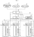
- FIG. 1 is a schematic block diagram showing the architecture of a system 10 for estimating the residual capacity of an energy storage system (ESS) according to an embodiment of the present disclosure.
- ESS energy storage system
- the system 10 is coupled to the ESS 11 including a plurality of battery racks 12 and a rack controller 13 operably coupled to each battery rack 12.
- the battery rack 12 includes a plurality of battery cells 12a.
- the plurality of battery cells 12a may be connected in series and/or in parallel.
- the battery cell 12a may be a lithium ion battery, and the present disclosure is not limited by the type of cell.
- the battery rack 12 has a known structure in the field of ESS technology.
- the battery rack 12 includes a rack in which the plurality of battery cells 12a may be mounted and an air conditioner such as a cooling fan to adjust the temperature.
- the plurality of battery racks 12 included in the ESS 11 is charged or discharged through a Power Conversion System (PCS) 20.
- the PCS 20 is a system that takes responsibility for changing the characteristics (frequency, voltage, etc.) of electricity or converting AC-DC to store power supplied from a renewable energy generator 21 using sunlight, wind and geothermal heat and/or a power grid 22 in the ESS 11 or supply energy stored in the ESS 11 to the power grid 22 and/or a power system 23.
- the battery rack 12 includes a voltage measurement unit 14, a current measurement unit 15 and a temperature measurement unit 16.
- the voltage measurement unit 14 measures a cell voltage at regular time intervals during the charging or discharging of the plurality of battery cells 12a, and outputs the cell voltage measurement value to a rack controller 13.
- the rack controller 13 receives the cell voltage measurement value and records it in a memory device 13a.
- the voltage measurement unit 14 may include a voltage measurement circuit known in the corresponding technical field.
- the current measurement unit 15 measures the magnitude of a charge/discharge current at regular time intervals during the charging or discharging of the plurality of battery cells 12a, and outputs the current measurement value to the rack controller 13.
- the rack controller 13 receives the measurement value of the charge/discharge current and records it in the memory device 13a. Additionally, the rack controller 13 determines a C-rate of the charge/discharge current and stores it in the memory device 13a.
- the C-rate of the charge/discharge current may be determined using the magnitude of the charge/discharge current and the capacity of the battery cell 12a.
- the current measurement unit 15 may be a hall effect sensor or a sense resistor to output a voltage value corresponding to the magnitude of the electric current. The voltage value may be converted into a current value by the Ohm's law.
- the temperature measurement unit 16 measures a temperature of the battery rack 12 at regular time intervals during the charging or discharging of the battery rack 12 and outputs the temperature measurement value to the rack controller 13.
- the rack controller 13 may receive the rack temperature measurement value and store it in the memory device 13a. Since the temperature of the battery rack 12 is uniformly controlled by the air-conditioner, the rack temperature measurement value may be regarded as a temperature measurement value of the battery cell 12a.
- the temperature measurement unit 16 may directly measure the temperature of the battery cell 12a.
- the temperature measurement unit 16 may be a thermocouple or a temperature measurement device to output the voltage value corresponding to the temperature.
- the voltage value may be converted to the temperature value using a voltage-temperature conversion lookup table (function).
- the rack controller 13 may determine a state of charge (SOC) of the battery rack 12 during the charging or discharging of the battery rack 12 and store it in the memory device 13a.
- the SOC of the battery rack 12 is the sum of SOCs of the battery cells 12a. Accordingly, the rack controller 13 may determine the SOCs of the plurality of battery cells 12a and determine the sum of SOCs as the SOC of the battery rack 12.
- the rack controller 13 may determine the SOC of the battery cell 12a using ampere counting.
- the initial value of SOC may be determined using open circuit voltage (OCV)-SOC lookup information. That is, when the stop of the charge/discharge of the battery rack 12 is maintained for a predetermined period of time, the rack controller 13 may set the cell voltage measured at the corresponding time as OCV, and determine the initial value of SOC using the OCV-SOC lookup information.
- the SOC of the battery cell 12a may be determined by accumulating the charge/discharge current on the basis of the initial value of SOC.
- the rack controller 13 may determine the SOC of each battery cell using an extended Kalman filter with input information associated with the voltage, the charge/discharge current and the temperature of the battery cell 12a.
- the extended Kalman filter used to determine the SOC from the voltage, the charge/discharge current and the temperature of the battery cell is well known in the corresponding technical field.
- the system 10 may include an ESS controller 17 operably coupled to the ESS 11.
- the ESS controller 17 may be connected to the rack controller 13 through a communication line.
- the communication line may be a line that supports at least one of communication protocols well known in the field of ESS technology, for example, CAN protocol, TCP/IP, Modbus TCP, Modbus RTU, RS-485 or the like.
- the ESS controller 17 may be connected to the rack controller 13 via near-field communication, for example, Bluetooth, Zigbee, Wifi or the like to enable communication between them.
- near-field communication for example, Bluetooth, Zigbee, Wifi or the like to enable communication between them.
- the ESS controller 17 may be also connected to an integrated ESS management device 18 through the communication line.
- the integrated ESS management device 18 is a device known as an Energy Management System (EMS) in the field of ESS technology.
- EMS Energy Management System
- the integrated ESS management device 18 optimally adjusts the amount and duration of charge/discharge of the ESS 11 through the integrated control of the PCS 20 and the ESS 11.
- the integrated EMS management device 18 is connected to the sensors and meters, and analyzes the charge/discharge data of the ESS 11 and performs control to operate the ESS 11 with optimum efficiency.
- the ESS controller 17 may periodically acquire the SOC of the battery rack 12 from the rack controller 13. To this end, the ESS controller 17 may transmit a SOC request message to the rack controller 13 at regular time intervals. Then, the rack controller 13 may read the SOC of the battery rack 12 from the memory device 13a and transmit it to the ESS controller 17 through the communication line. The ESS controller 17 may store the received SOC of the battery rack 12 in a memory device 17a together with a time stamp. Accordingly, the memory device 17a stores time-series data of the SOC of the battery rack 12.
- the ESS controller 17 may set an average value of SOCs of the battery racks 12 acquired at the same time using the following Equation 1 as a State Of Charge SOC ESS of the ESS 11 and store it in the memory device 17a. Accordingly, the memory device 17a stores time-series data of the State Of Charge SOC ESS of the ESS 11 acquired for a reference time period.
- SOC ESS is the SOC of the ESS 11.
- SOC Rack,k is the SOC of the k-th battery rack 12.
- n is the total number of battery racks 12.
- the ESS controller 17 may determine an actual usage pattern of the ESS 11 indicating a change in SOC of the ESS during the reference time period by referring to the State Of Charge SOC ESS information stored in the memory device 17a, and store the actual usage pattern in the memory device 17a.
- the reference time period may be 1 day.
- the ESS controller 17 may determine the actual usage pattern of the ESS 11 indicating the change in SOC of the ESS by referring to the time-series data of the State Of Charge SOC ESS periodically stored in the memory device 17a for last 24 hours.
- the reference time period may be set to be longer or shorter than 1 day.
- FIG. 2 is a graph showing an example of the actual usage pattern A of the ESS 11 according to an embodiment of the present disclosure.
- the actual usage pattern A is determined on the basis of 1 day.
- the actual usage pattern A has two charge ranges, two discharge ranges and four rest ranges, and shows changes in the State Of Charge SOC ESS of the ESS 11 for the reference time period.
- the charge range is a range in which the charge power is supplied from the renewable energy generator 21 and/or the power grid 22 to the ESS 11.
- the time period corresponding to the charge range is the time (nighttime) when the power generation efficiency of renewable energy is high or the power price of the power grid is low.
- the discharge range is a range in which the discharge power is supplied from the ESS 11 to the power grid 22 and/or the power system 23.
- the time period corresponding to the discharge range is a peak time of the power grid 22 or the time when the power system 23 needs power (for example, daytime).
- the time period corresponding to the rest range is a range in which the ESS 11 is stabilized after the charge or discharge of the ESS 11. That is, in the rest range, the battery cell 12a of the battery rack 12 is in stabilized state that polarization is mitigated.
- the voltage of the battery cell 12a measured at the end of the rest range may be used as OCV when determining the initial value of SOC.
- the actual usage pattern A may change depending on how the manager of the ESS 11 implements the usage policy of the ESS 11.
- the discharge range may increase.
- the discharge range may decrease and the rest range may be extended.
- the actual usage pattern A is different from the design usage pattern that was taken into account when determining the EOL lifespan of the ESS 11.
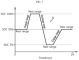
- FIG. 3 is a graph showing an example of the design usage pattern B of the ESS 11 according to an embodiment of the present disclosure.
- the design usage pattern B of an embodiment is determined on the basis of 1 day.
- the design usage pattern B has charge, discharge and rest ranges, and shows changes in the State Of Charge SOC ESS of the ESS 11 for the reference time period.
- the EOL lifespan of the ESS 11 is determined on the premise that the ESS 11 is repeatedly charged/discharged according to the design usage pattern.
- the actual usage pattern shown in FIG. 2 has two discharge ranges. Accordingly, when the ESS 11 is repeatedly charged/discharged according to the pattern shown in FIG. 2 , the ESS 11 is used more actively than the design usage pattern. Accordingly, when the ESS 11 is repeatedly charged/discharged according to the usage pattern shown in FIG. 2 , the ESS residual capacity at EOL is lower than the ESS residual capacity at EOL when the ESS 11 is repeatedly charged/discharged according to the design usage pattern of FIG. 3 .
- the ESS controller 17 may determine a first ESS residual capacity at EOL by applying an average of actual usage patterns determined for each reference time period over the whole period of the EOL lifespan.
- the first ESS residual capacity corresponds to the estimated residual capacity at EOL when the ESS 11 is repeatedly charged/discharged according to the actual usage pattern.
- the ESS controller 17 periodically acquires the State Of Charge SOC Rack,k of the battery rack 12 and the temperature T k and the charge/discharge C-rate c k of the battery rack from the rack controller 13 and stores it in the memory device 17a.
- the ESS controller 17 determines the State Of Charge SOC ESS of the ESS 11 by calculating the average value of State Of Charges SOC Rack,k of the battery racks 12 acquired at the same time using Equation 1 and stores it in the memory device 17a.
- the memory device 17a stores the time-series data associated with the State Of Charge SOC ESS of the ESS 11 and the temperature T k and the charge/discharge C-rate c k of the plurality of battery racks 12.
- the ESS controller 17 determines the actual usage pattern (see FIG. 2 ) of the ESS 11 using the time-series data of the State Of Charge SOC ESS of the ESS 11 calculated for the k-th reference time period and stores it in the memory device 17a.
- the ESS controller 17 determines a depth of discharge DoD k from the actual usage pattern determined for the k-th reference time period.
- the depth of discharge DoD k corresponds to the sum of SOC changes in each discharge range in the actual usage pattern.
- the depth of discharge DoD k increases.
- the depth of discharge DoD k decreases.
- the ESS controller 17 may determine a temperature decay rate A T,k corresponding to the temperature T k of the battery rack using a predefined correlation between temperature T and temperature decay rate A T .
- the correlation between the temperature T and the temperature decay rate A T may be determined through testing. That is, the correlation between the charge/discharge temperature T and the temperature decay rate A T may be defined as a lookup table or a lookup function by performing the charge/discharge cycling test on the battery cell 12a in different temperature conditions.
- the temperature T k used when determining the temperature decay rate A T,k may be the average value of the time-series data of the temperature T k of the plurality of battery racks 12 stored in the memory device 17a, but the present disclosure is not limited thereto. In a variation, the temperature T k may be the maximum, median or mode value of the time-series data of the temperature T k of the battery racks 12 stored in the memory device 17a.
- the ESS controller 17 may determine a C-rate decay rate A c,k corresponding to the charge/discharge C-rate c k using a predefined correlation between charge/discharge C-rate c and C-rate decay rate A c .
- the correlation between the charge/discharge C-rate c and the C-rate decay rate A c may be determined through testing. That is, the correlation between the charge/discharge C-rate c and the C-rate decay rate A c may be defined as a lookup table or a lookup function by performing the charge/discharge cycling test on the battery cell 12a in different charge/discharge C-rate conditions.
- the charge/discharge C-rate c k used when determining the C-rate decay rate A c,k may be the average value of the time-series data of the charge/discharge C-rate c k of the plurality of battery racks 12 stored in the memory device 17a, and the present disclosure is not limited thereto.
- the charge/discharge C-rate c k may be the maximum, median or mode value of the time-series data of the charge/discharge C-rate c k of the plurality of battery racks 12 stored in the memory device 17a.
- the ESS controller 17 may determine a DoD decay rate A DoD,k corresponding to the depth of discharge DoD k determined from the actual usage pattern using a predefined correlation between DoD and DoD decay rate A DoD .
- the correlation between the DoD and the DoD decay rate A DoD may be determined through testing. That is, the correlation between the DoD and the DoD decay rate A DoD may be defined as a lookup table or a lookup function by performing the charge/discharge cycling test on the battery cell 12a in different DoD conditions.
- the ESS controller 17 may determine the first ESS residual capacity Capacity 1 at EOL using the following Equation 2 and store it in the memory device 17a.
- the power conversion efficiency A is the power conversion efficiency of the PCS 20, and is a predetermined value according to the performance specification of the PCS 20.
- the capacity loss compensation ratio is a predefined factor considering the power consumption when the rack controller 13 is supplied with power from the battery rack 12, the power cable loss, the capacity difference between racks and the capacity difference between cells.
- n is the total number of days for which the ESS 11 has been used
- W is the total number of dates corresponding to the EOL lifespan. In case that the usage duration of the ESS 11 is 10 years and the EOL lifespan is 20 years, n is 365*10 and W is 365*20.
- the ESS controller 17 may record a first deviation between the first ESS residual capacity Capacity 1 and a reference residual capacity Capacity refer in the memory device 17a.
- the reference residual capacity Capacity refers to the ESS residual capacity at EOL when the ESS 11 is used over the whole period of the EOL lifespan according to the design usage pattern ( FIG. 3 ).
- the reference residual capacity Capacity refer may be pre-calculated through the following Equation 3 and recorded in the memory device 17a for reference.
- Capacity refer A T ⁇ A c ⁇ A DoD ⁇ W ⁇ A ⁇ B ⁇ E (A T : the temperature decay rate corresponding to the design usage temperature of the ESS, A C : the C-rate decay rate corresponding to the design charge/discharge C-rate of the ESS, A DoD : the DoD decay rate corresponding to the design DoD of ESS, A: the power conversion efficiency (predefined), B: the capacity loss compensation ratio (predefined), E: the design capacity of the ESS (predefined))
- the temperature decay rate A T may be determined using the predefined correlation between the temperature T of the battery rack 12 and the temperature decay rate A T .
- the C-rate decay rate A c may be determined using the predefined correlation between the charge/discharge C-rate c of the battery rack 12 and the C-rate decay rate A c .
- the DoD decay rate A DoD may be determined using the predefined correlation between the DoD and the DoD decay rate A DoD .
- the ESS controller 17 may record an event log including the occurrence time of the event in the memory device 17a.
- the first threshold may be set to 1% to 10% level of the reference residual capacity Capacity refer , but the present disclosure is not limited thereto.
- the ESS controller 17 may be configured to provide the event log to the integrated ESS management device 18. Additionally, the ESS controller 17 may provide the integrated ESS management device 18 with information associated with the first ESS residual capacity Capacity 1 , the reference residual capacity Capacity refer and the first deviation between them.
- the integrated ESS management device 18 may output the information associated with the first ESS residual capacity Capacity 1 , the reference residual capacity Capacity refer and the first deviation between them in a graphical user interface through a display.
- the integrated ESS management device 18 may output time-series data of the first ESS residual capacity Capacity 1 and time-series data of the first deviation in the form of a graph through the display.
- the ESS controller 17 may determine a second ESS residual capacity Capacity 2 at EOL by applying the average of actual usage patterns determined for each reference time period until the present time, and applying the design usage pattern of the ESS over the remaining period of the EOL lifespan from the present time.
- the ESS controller 17 periodically acquires the State Of Charge SOC Rack,k of the battery rack 12, and the temperature T k and the charge/discharge C-rate c k of the battery rack from the rack controller 13 for the k-th reference time period (1 day) and stores it in the memory device 17a (k is the sequence index, and is a natural number of 1 or greater).
- the ESS controller 17 determines the State Of Charge SOC ESS of the ESS 11 by calculating the average value of State Of Charges SOC Rack,k of the battery racks 12 acquired at the same time using Equation 1 and stores it in the memory device 17a.
- the memory device 17a stores the time-series data associated with the State Of Charge SOC ESS of the ESS 11 and the temperature T k and the charge/discharge C-rate c k of the plurality of battery racks 12.
- the ESS controller 17 determines the actual usage pattern (see FIG. 2 ) of the ESS 11 using the time-series data of the State Of Charge SOC ESS of the ESS 11 calculated for the k-th reference time period and stores it in the memory device 17a.
- the ESS controller 17 determines the depth of discharge DoD k from the actual usage pattern determined for the k-th reference time period.
- the depth of discharge DoD k corresponds to the sum of SOC changes in each discharge range in the actual usage pattern. As the ESS 11 is actively used, the depth of discharge DoD k increases. In contrast, as the ESS 11 is conservatively used, the depth of discharge DoD k decreases.
- the ESS controller 17 may determine the temperature decay rate A T,k corresponding to the temperature T k of the battery rack, the C-rate decay rate A c,k corresponding to the charge/discharge C-rate c k and the DoD decay rate A DoD,k corresponding to the depth of discharge DoD k determined from the actual usage pattern.
- the ESS controller 17 may determine the second ESS residual capacity Capacity 2 at EOL using the following Equation 4 and store it in the memory device 17a.
- the power conversion efficiency A is the power conversion efficiency of the PCS 20, and is a predetermined value according to the performance specification of the PCS 20.
- the capacity loss compensation ratio is a predefined factor considering the power consumption when the rack controller 13 is supplied with power from the battery rack 12, the power cable loss, the capacity difference between racks and the capacity difference between cells.
- n is the total number of days for which the ESS 11 has been used
- W is the total number of dates corresponding to the EOL lifespan. In case that the usage duration of the ESS 11 is 10 years and the EOL lifespan is 20 years, n is 365*10 and W is 365*20.
- the ESS controller 17 may record a second deviation between the second ESS residual capacity Capacity 2 and the reference residual capacity Capacity refer in the memory device 17a.
- the ESS controller 17 may record an event log including the occurrence time of the event in the memory device 17a.
- the second threshold may be set to a value of 1% to 10% level of the reference residual capacity Capacity refer , but the present disclosure is not limited thereto.
- the ESS controller 17 may be configured to provide the event log to the integrated ESS management device 18. Additionally, the ESS controller 17 may provide the integrated ESS management device 18 with information associated with the second ESS residual capacity Capacity 2 , the reference residual capacity Capacity refer and the second deviation between them.
- the integrated ESS management device 18 may output the information associated with the second ESS residual capacity Capacity 2 , the reference residual capacity Capacity refer and the second deviation between them in the graphical user interface through the display.
- the integrated ESS management device 18 may output time-series data of the second ESS residual capacity Capacity 2 and time-series data of the second deviation in the form of a graph through the display.
- the residual capacity at EOL is calculated considering each of the actual usage pattern of the ESS and the design usage pattern of the ESS and is stored and managed as log information, it is possible to omit the ESS residual capacity test that requires lots of time and costs.
- the ESS residual capacity at EOL is calculated based on two standards and provided to the customer, it may be helpful in managing the usage pattern of the ESS and establishing an additional ESS.
- the customer may reduce the daily usage capacity of the ESS or pre-establish an additional ESS.
- the customer may increase the daily DoD to increase the usage efficiency of the ESS.
- the ESS controller 17 may selectively include a processor, application-specific integrated circuit (ASIC), a chipset, a logic circuit, register, a communication modem, a data processing device or the like known in the corresponding technical field to execute various control logics.
- ASIC application-specific integrated circuit
- the memory devices 13a, 17a is not limited to a particular type, and may include any medium capable of recording and erasing information.
- the memory devices 13a, 17a may be hard disk, RAM, ROM, EEPROM, register or flash memory.
- the memory devices 13a, 17a may store and/or update and/or erase and/or transmit programs including the control logics performed by the controller and/or data generated when the control logics are executed, predefined lookup tables, functions, parameters, chemical/physical/electrical constants or the like.
- At least one of the control logics of the ESS controller 17 may be combined together, and the combined control logics may be written in computer-readable code and recorded in the memory device 17a.
- the code may be stored and executed in distributed computers connected via a network. Additionally, the functional programs, code and code segments for implementing the combined control logics can be easily inferred by programmers in the technical field pertaining to the present disclosure.
- FIGS. 4a and 4b are flowcharts showing the sequence of the method for estimating the residual capacity of the ESS according to an embodiment of the present disclosure.
- the steps shown in FIGS. 4a and 4b are performed by the ESS controller 17. Additionally, the reference time period is set to 1 day. In some cases, the reference time period may be shorter or longer than 1 day.
- step S10 the ESS controller 17 initializes the sequence index k of the reference time period to 1.
- step S20 the ESS controller 17 periodically acquires the State Of Charge SOC Rack,k , the temperature T k and the charge/discharge C-rate c k of the battery rack 12 from the rack controller 13 for the k-th reference time period (the current value is 1) and stores it in the memory device 17a.
- step S30 the ESS controller 17 sets the average value of State Of Charges SOC Rack,k of the battery racks 12 acquired at the same time as the State Of Charge SOC ESS of the ESS 11 and stores it in the memory device 17a. Accordingly, the memory device 17a stores the time-series data of the State Of Charge SOC ESS of the ESS 11 determined for each reference time period.
- step S40 the ESS controller 17 determines the actual usage pattern of the ESS 11 indicating the change in SOC of the ESS from the time-series data of the State Of Charge SOC ESS stored in the memory device 17a, and stores the actual usage pattern in the memory device 17a.
- step S50 the ESS controller 17 determines the depth of discharge DoD k from the actual usage pattern determined for the k-th reference time period.
- step S60 the ESS controller 17 determines the temperature decay rate A T,k corresponding to the temperature T k of the battery rack 12 using the predefined correlation between the temperature T and the temperature decay rate A T .
- the mean, median, maximum or mode value of temperatures of the plurality of battery racks 12 may be used.
- step S70 the ESS controller 17 determines the C-rate decay rate A c,k corresponding to the charge/discharge C-rate c k of the battery rack 12 using the predefined correlation between the charge/discharge C-rate c and the C-rate decay rate A c .
- the mean, median, maximum or mode value of C-rates of the plurality of battery racks 12 may be used.
- step S80 the ESS controller 17 determines the DoD decay rate A DoD,k corresponding to the depth of discharge DoD k determined from the actual usage pattern using the predefined correlation between the DoD and the DoD decay rate A DoD .
- step S90 the ESS controller 17 determines the first ESS residual capacity Capacity 1 at EOL by applying the condition that the average of actual usage patterns determined for each reference time period until the present time is applied over the whole period of the EOL lifespan using the following Equation 2, and stores it in the memory device 17a.
- step S100 the ESS controller 17 determines the first deviation between the first ESS residual capacity Capacity 1 and the reference residual capacity Capacity refer and stores it in the memory device 17a.
- the reference residual capacity Capacity refers to the ESS residual capacity at EOL when the ESS 11 is used over the whole period of the EOL lifespan according to the design usage pattern of the ESS 11.
- step S110 when an event occurred in which the first deviation between the first ESS residual capacity Capacity 1 and the reference residual capacity Capacity refer is equal to or larger than the first threshold, the ESS controller 17 may store the event log including the occurrence time of the event in the memory device 17a.
- the first threshold may be set to 1% to 10% level of the reference residual capacity Capacity refer , but the present disclosure is not limited thereto.
- the ESS controller 17 provides the event log to the integrated ESS management device 18.
- the ESS controller 17 may provide the integrated ESS management device 18 with the information associated with the first ESS residual capacity Capacity 1 , the reference residual capacity Capacity refer and the first deviation between them together when providing the event log.
- the integrated ESS management device 18 may output the information associated with the first ESS residual capacity Capacity 1 , the reference residual capacity Capacity refer and the first deviation between them in the graphical user interface through the display.
- the integrated ESS management device 18 may output the time-series data of the first ESS residual capacity Capacity 1 and the time-series data of the first deviation in the form of a graph through the display.
- step S130 is performed.
- the ESS controller 17 determines if the reference time period has elapsed. When the determination of the step S130 is NO, the ESS controller 17 holds the process. In contrast, when the determination of the step S130 is YES, in the step S140, the ESS controller 17 increases the reference time period sequence index k by 1, moves the process to the step S20, and then performs the steps S20 to 120 again for the next reference time period.
- the event log may be stored in the memory device 17a, and the event log may be provided to the integrated ESS management device 18.
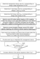
- FIG. 5 is a flowchart showing the sequence of the method for estimating the residual capacity of the ESS according to another embodiment of the present disclosure.
- the ESS controller 17 equally performs the steps S10 to S80 of FIG. 4a , and after that, selectively performs the steps S150 to S230 of FIG. 5 .
- step S150 the ESS controller 17 determines the temperature decay rate A T corresponding to the design usage temperature of the ESS 11 using the predefined correlation between the temperature T and the temperature decay rate A T .
- step S160 the C-rate decay rate A c corresponding to the design charge/discharge C-rate of the ESS 11 is determined using the predefined correlation between the charge/discharge C-rate c and the C-rate decay rate A c .
- step S170 the DoD decay rate A DoD corresponding to the design DoD of the ESS 11 is determined using the predefined correlation between the DoD and the DoD decay rate A DoD .
- the ESS controller 17 may determine the second ESS residual capacity Capacity 2 at EOL through the following Equation 4 by applying the condition that the average of actual usage patterns determined for each reference time period is applied for a time period until the present time and the design usage pattern of the ESS is applied for the remaining period of the EOL lifespan from the present time.
- step S190 the ESS controller 17 determines the second deviation between the second ESS residual capacity Capacity 2 and the reference residual capacity Capacity refer and stores it in the memory device 17a.
- the reference residual capacity Capacity refers to the ESS residual capacity at EOL when the ESS 11 is used over the whole period of the EOL lifespan according to the design usage pattern of the ESS 11.
- step S200 when an event occurred in which the second deviation between the second ESS residual capacity Capacity 2 and the reference residual capacity Capacity refer is equal to or larger than the second threshold, the ESS controller 17 may store the event log including the occurrence time of the event in the memory device 17a.
- the second threshold may be set to 1% to 10% level of the reference residual capacity Capacity refer , but the present disclosure is not limited thereto.
- the ESS controller 17 provides the event log to the integrated ESS management device 18.
- the ESS controller 17 may provide the integrated ESS management device 18 with the information associated with the second ESS residual capacity Capacity 2 , the reference residual capacity Capacity refer and the second deviation between them together when providing the event log.
- the integrated ESS management device 18 may output the information associated with the second ESS residual capacity Capacity 2 , the reference residual capacity Capacity refer and the second deviation between them in the graphical user interface through the display.
- the integrated ESS management device 18 may output the time-series data of the second ESS residual capacity Capacity 2 and the time-series data of the second deviation in the form of a graph through the display.
- step S220 is performed.
- the ESS controller 17 determines if the reference time period has elapsed. When the determination of the step S220 is NO, the ESS controller 17 holds the process. In contrast, when the determination of the step S220 is YES, in step S230, the ESS controller 17 increases the reference time period sequence index k by 1, move the process to the step S20 and performs the steps S20 to 80 of FIG. 4a and the steps S150 to S210 of FIG. 5 again for the next reference time period.
- the second ESS residual capacity Capacity 2 may be calculated, and when the second deviation between the second ESS residual capacity Capacity 2 and the reference residual capacity Capacity refer is equal to or higher than the second threshold, and the event log may be stored in the memory device 17a, and the event log may be provided to the integrated ESS management device 18.
- the embodiment of FIGS. 4a and 4b and the embodiment of FIG. 5 may be performed for the reference time period at the same time.
- the event log may be generated, and recorded in the memory device 17a and provided to the integrated ESS management device 18.
- the integrated ESS management device 18 may output at least one selected from the time-series data of the first ESS residual capacity Capacity 1 , the time-series data of the second ESS residual capacity Capacity 2 , the time-series data of the first deviation and the time-series data of the second deviation as a graph through the display.
- the ESS operator may optimally control the ESS usage pattern to follow the design usage pattern of the ESS 11. Additionally, when there is a large difference between the design usage pattern and the actual usage pattern, the ESS operator may take pre-action, for example, establishing additional ESSs, under the discussion with the ESS manufacturer.
Landscapes
- Engineering & Computer Science (AREA)
- Chemical Kinetics & Catalysis (AREA)
- General Chemical & Material Sciences (AREA)
- Electrochemistry (AREA)
- Chemical & Material Sciences (AREA)
- General Physics & Mathematics (AREA)
- Physics & Mathematics (AREA)
- Manufacturing & Machinery (AREA)
- Microelectronics & Electronic Packaging (AREA)
- Power Engineering (AREA)
- Charge And Discharge Circuits For Batteries Or The Like (AREA)
- Tests Of Electric Status Of Batteries (AREA)
- Supply And Distribution Of Alternating Current (AREA)
- Secondary Cells (AREA)
Applications Claiming Priority (2)
| Application Number | Priority Date | Filing Date | Title |
|---|---|---|---|
| KR1020210131983A KR20230048957A (ko) | 2021-10-05 | 2021-10-05 | Ess 잔존용량 예측 시스템 및 방법 |
| PCT/KR2022/015014 WO2023059077A1 (ko) | 2021-10-05 | 2022-10-05 | Ess 잔존용량 예측 시스템 및 방법 |
Publications (2)
| Publication Number | Publication Date |
|---|---|
| EP4283757A1 true EP4283757A1 (de) | 2023-11-29 |
| EP4283757A4 EP4283757A4 (de) | 2024-10-02 |
Family
ID=85803597
Family Applications (1)
| Application Number | Title | Priority Date | Filing Date |
|---|---|---|---|
| EP22878898.0A Pending EP4283757A4 (de) | 2021-10-05 | 2022-10-05 | System zur schätzung der restkapazität eines energiespeichersystems (ess) und verfahren dafür |
Country Status (6)
| Country | Link |
|---|---|
| US (1) | US20240079660A1 (de) |
| EP (1) | EP4283757A4 (de) |
| JP (1) | JP7688135B2 (de) |
| KR (1) | KR20230048957A (de) |
| CN (1) | CN116848698A (de) |
| WO (1) | WO2023059077A1 (de) |
Families Citing this family (5)
| Publication number | Priority date | Publication date | Assignee | Title |
|---|---|---|---|---|
| KR102882635B1 (ko) * | 2021-01-13 | 2025-11-05 | 주식회사 엘지에너지솔루션 | 배터리 뱅크 전력 제어 장치 및 방법 |
| US12500436B2 (en) * | 2021-10-20 | 2025-12-16 | China Energy Investment Corporation Limited | Controller, system, and method for managing discharge or charge of heterogeneous battery packs |
| KR102862821B1 (ko) * | 2024-03-29 | 2025-09-22 | 비나텍주식회사 | 슈퍼커패시터의 충방전 상태를 모니터링 및 출력하는 인디케이터 장치 및 이를 포함하는 슈퍼커패시터 랙 |
| CN118899954A (zh) * | 2024-07-15 | 2024-11-05 | 苏州市壹米新能源科技有限公司 | 一种光伏储能系统的控制方法 |
| KR102899750B1 (ko) * | 2024-10-17 | 2025-12-12 | 한국에너지기술연구원 | 배터리 건전성 관리 및 효율 운전 방법 및 장치 |
Family Cites Families (18)
| Publication number | Priority date | Publication date | Assignee | Title |
|---|---|---|---|---|
| JPS5628476A (en) * | 1979-08-14 | 1981-03-20 | Shin Kobe Electric Mach Co Ltd | Remained capacity meter for storage battery |
| KR20120134415A (ko) * | 2011-06-02 | 2012-12-12 | 에스케이이노베이션 주식회사 | Ess의 배터리 수명 예측 시스템 및 그 방법 |
| JP2013181875A (ja) | 2012-03-02 | 2013-09-12 | Honda Motor Co Ltd | 二次電池の劣化率算出方法、二次電池の寿命予測方法、二次電池の劣化率算出システムおよび二次電池の寿命予測システム |
| JP5768001B2 (ja) * | 2012-04-23 | 2015-08-26 | 株式会社日立製作所 | 電池システムのメンテナンス管理システム及び方法 |
| KR101893957B1 (ko) * | 2013-08-19 | 2018-08-31 | 삼성에스디아이 주식회사 | 배터리 팩, 배터리 팩을 포함하는 장치, 및 배터리 팩의 관리 방법 |
| JP2015059924A (ja) * | 2013-09-20 | 2015-03-30 | 株式会社東芝 | 蓄電池性能評価装置およびその方法 |
| CN103499794B (zh) * | 2013-10-14 | 2016-05-11 | 北京华电天仁电力控制技术有限公司 | 一种储能电池剩余容量估算方法及装置 |
| KR101726483B1 (ko) * | 2014-12-04 | 2017-04-12 | 주식회사 엘지화학 | 배터리 사용 패턴 분석 장치 및 방법 |
| KR102343967B1 (ko) * | 2014-12-04 | 2021-12-28 | 삼성전자주식회사 | 배터리의 상태를 추정하는 방법 및 장치 |
| KR101651772B1 (ko) * | 2014-12-31 | 2016-08-29 | 주식회사 포스코아이씨티 | 다수의 에너지 저장의 전력 제어 시스템 |
| US11150304B2 (en) * | 2015-11-25 | 2021-10-19 | Hewlett-Packard Development Company, L.P. | Battery performance prediction |
| KR102711054B1 (ko) * | 2018-11-22 | 2024-09-27 | 주식회사 엘지에너지솔루션 | Ess의 저전압 배터리 랙 관리 장치 및 방법 |
| KR102785786B1 (ko) * | 2019-03-21 | 2025-03-26 | 주식회사 엘지에너지솔루션 | 배터리 뱅크 제어 장치 및 방법 |
| KR20210024962A (ko) * | 2019-08-26 | 2021-03-08 | 오토시맨틱스 주식회사 | Ess 배터리의 상태진단 및 수명예측을 위한 장치 및 방법 |
| KR102186036B1 (ko) | 2019-12-12 | 2020-12-03 | (주)연우 | 탄성 부재 및 이를 포함하는 펌프 조립체 |
| KR102210716B1 (ko) * | 2020-06-17 | 2021-02-03 | 주식회사 나산전기산업 | 배터리의 충방전 특성을 사용하여 배터리를 전기 에너지를 저장하기 위한 ess 시스템 |
| KR102759171B1 (ko) | 2020-08-13 | 2025-01-24 | 주식회사 엘지에너지솔루션 | 배터리 수명 예측 장치 및 방법 |
| KR102882635B1 (ko) | 2021-01-13 | 2025-11-05 | 주식회사 엘지에너지솔루션 | 배터리 뱅크 전력 제어 장치 및 방법 |
-
2021
- 2021-10-05 KR KR1020210131983A patent/KR20230048957A/ko active Pending
-
2022
- 2022-10-05 JP JP2023542619A patent/JP7688135B2/ja active Active
- 2022-10-05 EP EP22878898.0A patent/EP4283757A4/de active Pending
- 2022-10-05 US US18/272,407 patent/US20240079660A1/en active Pending
- 2022-10-05 CN CN202280010509.7A patent/CN116848698A/zh active Pending
- 2022-10-05 WO PCT/KR2022/015014 patent/WO2023059077A1/ko not_active Ceased
Also Published As
| Publication number | Publication date |
|---|---|
| KR20230048957A (ko) | 2023-04-12 |
| CN116848698A (zh) | 2023-10-03 |
| EP4283757A4 (de) | 2024-10-02 |
| JP2024509037A (ja) | 2024-02-29 |
| WO2023059077A1 (ko) | 2023-04-13 |
| JP7688135B2 (ja) | 2025-06-03 |
| US20240079660A1 (en) | 2024-03-07 |
Similar Documents
| Publication | Publication Date | Title |
|---|---|---|
| EP4283757A1 (de) | System zur schätzung der restkapazität eines energiespeichersystems (ess) und verfahren dafür | |
| CN108375739B (zh) | 电动车锂电池的荷电状态估算方法与荷电状态估算系统 | |
| JP6686166B2 (ja) | 電池ヘルス状態を検出する装置及び方法 | |
| EP3929606B1 (de) | Batterieverwaltungssystem, batteriepack, elektrofahrzeug und batterieverwaltungsverfahren | |
| CN101163980B (zh) | 锂硫可再充电电池电量测量系统和方法 | |
| CN104471415B (zh) | 用于电池应用的嵌入式芯片 | |
| CN104678316B (zh) | 锂离子电池荷电状态估算方法和装置 | |
| US5739670A (en) | Method for diagnosing battery condition | |
| US20170115355A1 (en) | Maximum capacity estimator for battery state of health and state of charge determinations | |
| CN111983495A (zh) | 电池组健康度确定方法及相关装置 | |
| US20220179003A1 (en) | Characterisation of lithium plating in rechargeable batteries | |
| CN102540089A (zh) | 动态电池容量估计 | |
| Magnor et al. | Concept of a battery aging model for lithium-ion batteries considering the lifetime dependency on the operation strategy | |
| JP2008134060A (ja) | 蓄電装置の異常検出装置、蓄電装置の異常検出方法及びその異常検出プログラム | |
| CN102998626A (zh) | 用于确定电池组健康状态的系统和方法 | |
| CN113203952A (zh) | 采用电压斜率容量和动态锚的电池容量估算方法与系统 | |
| CN112924866A (zh) | 容量保持率的检测方法、检测装置、车辆及存储介质 | |
| Tahir et al. | Modeling and evaluation of nickel manganese cobalt based Li-ion storage for stationary applications | |
| KR101474401B1 (ko) | 이차전지 배터리 팩의 상태 추정장치와 방법 및 이를 이용한 배터리 팩 | |
| EP4343350B1 (de) | Vorrichtung und verfahren zur erkennung einer beschädigten batteriezelle | |
| US9702941B2 (en) | Method and devices for making available information for the purpose of performing maintenance and servicing of a battery | |
| JP6494431B2 (ja) | 蓄電デバイスの劣化診断装置 | |
| CN119716615B (zh) | 一种soh标定方法、装置、设备及介质 | |
| Lystianingrum et al. | State of health and life estimation methods for supercapacitors | |
| KR101630409B1 (ko) | 이차전지 배터리 팩의 상태 추정장치와 방법 및 이를 이용한 배터리 팩 |
Legal Events
| Date | Code | Title | Description |
|---|---|---|---|
| STAA | Information on the status of an ep patent application or granted ep patent |
Free format text: STATUS: THE INTERNATIONAL PUBLICATION HAS BEEN MADE |
|
| PUAI | Public reference made under article 153(3) epc to a published international application that has entered the european phase |
Free format text: ORIGINAL CODE: 0009012 |
|
| STAA | Information on the status of an ep patent application or granted ep patent |
Free format text: STATUS: REQUEST FOR EXAMINATION WAS MADE |
|
| 17P | Request for examination filed |
Effective date: 20230824 |
|
| AK | Designated contracting states |
Kind code of ref document: A1 Designated state(s): AL AT BE BG CH CY CZ DE DK EE ES FI FR GB GR HR HU IE IS IT LI LT LU LV MC ME MK MT NL NO PL PT RO RS SE SI SK SM TR |
|
| A4 | Supplementary search report drawn up and despatched |
Effective date: 20240904 |
|
| RIC1 | Information provided on ipc code assigned before grant |
Ipc: H02J 7/00 20060101ALI20240829BHEP Ipc: G01R 31/387 20190101ALI20240829BHEP Ipc: G01R 31/396 20190101ALI20240829BHEP Ipc: G01R 31/36 20200101ALI20240829BHEP Ipc: G01R 31/392 20190101ALI20240829BHEP Ipc: G01R 31/382 20190101ALI20240829BHEP Ipc: H01M 10/42 20060101ALI20240829BHEP Ipc: H01M 10/44 20060101ALI20240829BHEP Ipc: H01M 10/48 20060101AFI20240829BHEP |
|
| DAV | Request for validation of the european patent (deleted) | ||
| DAX | Request for extension of the european patent (deleted) |