EP4283266A1 - Vorrichtung und verfahren zur ermittlung einer farbe eines gegenstandes - Google Patents
Vorrichtung und verfahren zur ermittlung einer farbe eines gegenstandes Download PDFInfo
- Publication number
- EP4283266A1 EP4283266A1 EP22175223.1A EP22175223A EP4283266A1 EP 4283266 A1 EP4283266 A1 EP 4283266A1 EP 22175223 A EP22175223 A EP 22175223A EP 4283266 A1 EP4283266 A1 EP 4283266A1
- Authority
- EP
- European Patent Office
- Prior art keywords
- light
- pulse
- light source
- group
- distance
- Prior art date
- Legal status (The legal status is an assumption and is not a legal conclusion. Google has not performed a legal analysis and makes no representation as to the accuracy of the status listed.)
- Granted
Links
Images


Classifications
-
- G—PHYSICS
- G01—MEASURING; TESTING
- G01J—MEASUREMENT OF INTENSITY, VELOCITY, SPECTRAL CONTENT, POLARISATION, PHASE OR PULSE CHARACTERISTICS OF INFRARED, VISIBLE OR ULTRAVIOLET LIGHT; COLORIMETRY; RADIATION PYROMETRY
- G01J3/00—Spectrometry; Spectrophotometry; Monochromators; Measuring colours
- G01J3/46—Measurement of colour; Colour measuring devices, e.g. colorimeters
- G01J3/50—Measurement of colour; Colour measuring devices, e.g. colorimeters using electric radiation detectors
- G01J3/501—Colorimeters using spectrally-selective light sources, e.g. LEDs
-
- G—PHYSICS
- G01—MEASURING; TESTING
- G01J—MEASUREMENT OF INTENSITY, VELOCITY, SPECTRAL CONTENT, POLARISATION, PHASE OR PULSE CHARACTERISTICS OF INFRARED, VISIBLE OR ULTRAVIOLET LIGHT; COLORIMETRY; RADIATION PYROMETRY
- G01J3/00—Spectrometry; Spectrophotometry; Monochromators; Measuring colours
- G01J3/02—Details
- G01J3/0205—Optical elements not provided otherwise, e.g. optical manifolds, diffusers, windows
- G01J3/0208—Optical elements not provided otherwise, e.g. optical manifolds, diffusers, windows using focussing or collimating elements, e.g. lenses or mirrors; performing aberration correction
-
- G—PHYSICS
- G01—MEASURING; TESTING
- G01J—MEASUREMENT OF INTENSITY, VELOCITY, SPECTRAL CONTENT, POLARISATION, PHASE OR PULSE CHARACTERISTICS OF INFRARED, VISIBLE OR ULTRAVIOLET LIGHT; COLORIMETRY; RADIATION PYROMETRY
- G01J3/00—Spectrometry; Spectrophotometry; Monochromators; Measuring colours
- G01J3/02—Details
- G01J3/0264—Electrical interface; User interface
Definitions
- the invention relates to a device and a method for determining a color of an object.
- Various spectrally different signals are fed to a color sensor.
- a spectral division can take place on the transmitter side or on the receiver side. If the transmitter side is divided, the color sensor is particularly susceptible to stray light.
- the device includes a transmitting unit, a control unit, a receiving unit and an evaluation unit.
- the transmitting unit comprises a light element with a first light source, which is designed to emit light in a first predefined wavelength range, a second light source, which is designed to emit light in a second wavelength range that is different from the first wavelength report, and a third light source that is designed to emit light in a third wavelength range that is different from the first wavelength range and from the second wavelength range.
- the first, second and third wavelength ranges lie in particular in the spectrum of visible light.
- the three wavelength ranges are in the red, green and blue range, and more particularly in the orange-red, green-yellow and blue range.
- the three wavelength ranges can also partially overlap spectrally.
- the first, second and third light sources are designed in particular as semiconductor light sources, in particular light-emitting diodes.
- the first, second and third light sources are in particular phosphorus-based light-emitting diodes, and more particularly phosphor-converted light-emitting diodes. These have a high spectral width with sufficient response time.
- the transmitting unit also includes transmitting optics that are designed to direct the emitted light from the first light source, the second light source and the third light source onto an object.
- the transmitting unit has one or more lenses and/or one or more mirrors that direct the light emitted by the three light sources onto an object.
- the transmission optics also include a bundling optics, which bundle the three light beams from the three light sources into one light beam.
- the control unit of the device is designed to control the first light source, the second light source and the third light source, in such a way that the first light source emits a first pulse group comprising at least two successive light pulses with a predefined pulse distance from one another, and the second light source comprises a second pulse group at least two successive light pulses are emitted with a predefined pulse distance from one another and the third light source emits a third pulse group comprising at least two successive light pulses with a predefined pulse distance from one another.
- first pulse group, the second pulse group and the third pulse group each comprise exactly three consecutive light pulses.
- first pulse group, the second pulse group and the third pulse group each comprise more than three light pulses, for example four, five or ten light pulses.
- the control unit is designed to emit the first pulse group, the second pulse group and the third pulse group in such a way that they follow one another at a (respective) predefined group distance.
- the receiving unit of the device comprises a receiving element and receiving optics, which are designed to receive light remitted by the object and to direct it onto the receiving element.
- the receiving element is a sensor that is designed to detect light in the wavelength range of the three light sources.
- the receiving optics include one or more lenses and/or one or more mirrors which direct the light remitted by the object onto the receiving element.
- the evaluation unit of the device is designed to evaluate the light received by the receiving element and thus determine a color of the object.
- the evaluation unit uses a processor, such as a microcontroller.
- the evaluation unit can also use an analog-digital converter, which converts an analog signal from the receiving element into a digital signal.
- the evaluation unit can use an amplifier, in particular a transimpedance amplifier, to amplify the received signal.
- the solution according to the invention in particular the pulse pattern according to the invention, enables particularly robust color recognition.
- the pulse pattern according to the invention is insensitive to interference, such as extraneous light, and is nevertheless particularly precise.
- the evaluation unit uses a filter with a finite impulse response to determine the color of the object.
- a finite impulse response filter which can also be referred to as an FIR filter or transversal filter, is a filter that produces an impulse response of finite length and is therefore particularly stable against oscillations.
- the FIR filter is particularly digital.
- the FIR filter is a so-called Nuttall filter or an FIR filter that uses a Nuttall window.
- the finite impulse response filter is a filter of order 10 or greater.
- the filter is a filter of order 12.
- the order of the filter is greater than or equal to the number of clock cycles of a pulse group plus twice the number of clock cycles of the group spacing.
- the sum of the twelve coefficients for a filter of order 12 is zero. This enables a high-pass characteristic.
- control unit is further designed to control the first light source, the second light source and the third light source in such a way that the first light source, the second light source or the third light source emits a fourth pulse group comprising a reference light pulse which is directed at a predefined group distance third pulse group follows.
- the reference light pulse serves to compensate for fluctuations in brightness that arise, for example, due to temperature fluctuations.
- the evaluation unit can in particular be designed to use a reference light receiver to evaluate the light remitted by the reference light pulse, in particular its power, and to correct brightness fluctuations based on this.
- the fourth pulse group comprising the reference light pulse can be emitted in particular after a total of nine pulse groups without a reference light pulse.
- the three light sources are controlled in such a way that the first pulse group in the first wavelength range, followed by the second pulse group in the second wavelength range, followed by the third pulse group in the third wavelength range, followed by the first pulse group in the first wavelength range, followed by the second pulse group in the second wavelength range, followed by the third pulse group in the third wavelength range, followed by the first pulse group in the first wavelength range, followed by the second pulse group in the second wavelength range, followed by the third pulse group in the third wavelength range, followed by the fourth pulse group is emitted with the individual reference light pulse.
- the first, second and third pulse groups are each repeated three times in succession before the fourth pulse group is emitted.
- the group spacing is three clock cycles, the pulse spacing is one clock cycle and the pulse duration is also one clock cycle long. This results in a particularly compact pulse pattern.
- the clock cycle is between 0.5 ⁇ s and 2.0 ⁇ s.
- the clock cycle is between 1.0 ⁇ s and 1.5 ⁇ s.
- the clock cycle is 1.33 ⁇ s. This clock cycle is particularly advantageous for the pulse pattern according to the invention.
- the task mentioned at the outset is also solved by a method for determining a color of an object, comprising the steps of controlling a first light source in order to emit a first pulse group comprising three successive light pulses with a predefined pulse distance from one another, controlling a second light source in order to produce a second pulse group comprising emitting three consecutive light pulses with a predefined pulse distance from one another, controlling a third light source in order to emit a third pulse group comprising three consecutive light pulses with a predefined pulse distance from one another and evaluating light remitted by an object in order to determine a color of the object.
- the method further comprises controlling the first light source, the second light source and the third light source, so that there is a predefined group distance between the first pulse group, the second pulse group and the third pulse group, in which none of the three light sources emits light.
- Fig. 1 a schematic view of a device 10 for determining a color of an object.
- the device 10 includes a transmitting unit 100, a control unit 200, a receiving unit 300 and an evaluation unit 400.
- the transmitting unit 100 includes a light element, comprising a first light source that is designed to emit light in a first predefined wavelength range, a second light source that is designed to emit light in a second wavelength range that is different from the first wavelength report , and a third light source configured to emit light in a third wavelength range that is different from the first wavelength range and the second wavelength range.
- the transmission unit 100 also includes transmission optics that are designed to direct the emitted light from the first light source, the second light source and the third light source onto an object.
- the light element, the first, second and third light sources as well as the transmitting optics are not shown for reasons of clarity.
- the control unit 200 is designed to control the first light source, the second light source and the third light source in such a way that the first light source emits a first pulse group comprising at least two successive light pulses with a predefined pulse distance from one another, and the second light source emits a second pulse group comprising at least two successive light pulses with a predefined pulse distance from one another and the third light source emits a third pulse group comprising at least two successive light pulses with a predefined pulse distance from one another, wherein the first pulse group, the second pulse group and the third pulse group follow one another at at least a predefined group distance.
- the receiving unit 300 comprises a receiving element and receiving optics, which are designed to receive light remitted from the object and direct it onto the receiving element, the receiving element and the receiving optics not being shown for reasons of clarity.
- the evaluation unit 400 is designed to evaluate light received by the receiving element and to determine a color of the object.
- control unit 200 and the evaluation unit 400 are related to the following Fig. 2 described.
- Fig. 2 shows a time sequence diagram of a device and a method for determining a color of an object.
- the time is plotted on the right-hand axis and on the vertical axis, from top to bottom, in the first line 101 a time sequence of the emitted light pulses, in the second line 201 a time sequence of a clock of a clock generator and in the third line 401 a time sequence
- the sequence of a signal received at the evaluation unit is plotted.
- the control unit described controls the first light source so that it emits a first light pulse 111, a second light pulse 112 and a third light pulse 113 in a first predefined wavelength, which is green in this example.
- the control unit controls the second light source so that it emits a first light pulse 121, a second light pulse 122 and a third light pulse 123 in a second predefined wavelength, which is blue in this example.
- the control unit controls the third light source so that it emits a first light pulse 131, a second light pulse 132 and a third light pulse 133 in a second predefined wavelength, which is red in this example.
- the control unit controls the first, second or third light source so that one of the first, second or third light sources emits a reference light pulse 141, which forms a fourth pulse group 140.
- the reference light pulse 141 can also be omitted.
- the control unit controls the first light source, the second light source and the third light source in such a way that there is a predefined group distance 150 between the first pulse group 110 and the second pulse group 120, and a predefined group distance 150 between the second pulse group 120 and the third pulse group 130 and that there is a predefined group distance 150 between the third pulse group 130 and the fourth pulse group 140.
- the group distances 150 between the first pulse group 110, the second pulse group 120, the third pulse group 130 and the fourth pulse group 140 are the same size. No light is emitted in these group spacings 150.
- the starting distance can be equal to the group distance of 150.
- the clock of the clock generator determines both the control unit and thus the emission of the light pulses, as well as the evaluation unit and thus the scanning of the receiving element.
- This is initially followed by three clock cycles 1, 2 and 3, in which no light is emitted, followed by a clock cycle 4, in which the first green light pulse 111 is emitted, followed by a clock cycle 5 in which no light pulse is emitted, followed by a clock cycle 6 in which the second basic light pulse 112 is emitted, followed by a clock cycle 7 in which no light pulse is emitted, followed by a clock cycle 8 in which the third reasons light pulse is emitted.
- This is followed by three clock cycles 9, 10 and 11 in which no light is emitted.
- the bar pattern repeats itself from the beginning. In particular, it can start again immediately after the 28th bar. Alternatively, there can be a pause of any length before the timing pattern starts again from the beginning.
- the color of the fourth pulse group varies alternately or one after the other in the color of the first, second or third light source. For example, if in the in Fig. 2 In the example shown, the fourth pulse group is emitted in green, in the next clock scheme the fourth pulse group is emitted in blue and in the following clock scheme in red.
- the clock cycle is between 0.5 ⁇ s and 2.0 ⁇ s, in particular 1.3 ⁇ s.
- the third line 401 shows what the evaluation unit receives. It can be seen that the evaluation unit first receives a signal without influence from the transmitting unit, a so-called background signal, for three clock cycles 1, 2, 3, followed by a clock cycle 4 in which it receives a green, followed by a clock cycle 5 in which it only receives the background signal, followed by a clock cycle 6 in which it receives a green, followed by a clock cycle 7 in which it only receives the background signal, followed by a clock cycle 8 in which it receives a green.
- a so-called background signal for three clock cycles 1, 2, 3, followed by a clock cycle 4 in which it receives a green, followed by a clock cycle 5 in which it only receives the background signal, followed by a clock cycle 6 in which it receives a green, followed by a clock cycle 7 in which it only receives the background signal, followed by a clock cycle 8 in which it receives a green.
- the clock cycles 1, 2, 3 represent the starting distance 155, the clock cycles 4 to 8 the first pulse group 110, the clock cycles 9 to 11 the group distance 150, the clock cycles 12 to 16 the second pulse group 120, the clock cycles 17 to 19 the group distance 150, the clock cycles 20 to 24 the third pulse group 130, the clock cycles 25 to 27 the group spacing 150 and the clock cycle 28 the fourth pulse group.
- the evaluation unit is designed to determine the color of the object particularly well.
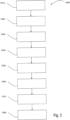
- Fig. 3 shows a flowchart of a method 1000 for determining a color of an object.
- the method 1000 begins in a first step 1010 in which a first light source is controlled in order to emit a first pulse group comprising three successive light pulses with a predefined pulse spacing from one another, which are directed at an object.
- a predefined group distance follows in which no light pulses are emitted.
- a second light source is controlled in order to emit a second pulse group comprising three consecutive light pulses with a predefined pulse distance from one another, which are directed at the object.
- a predefined group distance follows in which no light pulses are emitted.
- a third light source is controlled in order to emit a third pulse group comprising three consecutive light pulses with a predefined pulse distance from one another, which are directed at the object.
- a predefined group distance follows in which no light pulses are emitted.
- the first, second or third light source is controlled to emit a fourth pulse group comprising a light pulse that is directed at the object.
- step 1080 the light remitted by an object is evaluated to determine a color of the object.
- step 1080 can be carried out continuously or permanently in order to evaluate each individual light pulse emitted.
- Step 1070 can be carried out in particular optionally.
- the method is such that steps 1010 to 1060 are repeated two, three or more times before step 1070 occurs once.
- a further step can take place, in particular once, in which no light pulses are emitted at a predefined starting distance.
Landscapes
- Physics & Mathematics (AREA)
- Spectroscopy & Molecular Physics (AREA)
- General Physics & Mathematics (AREA)
- Spectrometry And Color Measurement (AREA)
Abstract
Description
- Die Erfindung betrifft eine Vorrichtung und ein Verfahren zur Ermittlung einer Farbe eines Gegenstands.
- Vorrichtungen und Verfahren zur Ermittlung einer Farbe eines Gegenstands sind prinzipiell bekannt. Dabei werden einem Farbsensor verschiedene spektral unterschiedliche Signale zugeführt. Eine spektrale Aufteilung kann dabei senderseitig oder empfängerseitig erfolgen. Bei einer senderseitigen Aufteilung ist der Farbsensor besonders anfällig für Störlicht.
- Es ist daher eine Aufgabe der vorliegenden Erfindung, eine verbesserte Vorrichtung ein verbessertes Verfahren zur Ermittlung einer Farbe eines Gegenstands anzugeben.
- Diese Aufgabe wird zunächst gelöst durch eine Vorrichtung zur Ermittlung einer Farbe eines Gegenstands. Die Vorrichtung umfasst dabei eine Sendeeinheit eine Steuereinheit, eine Empfangseinheit und eine Auswerteeinheit.
- Die Sendeeinheit umfasst dabei ein Lichtelement mit einer ersten Lichtquelle, die ausgebildet ist, Licht in einem ersten vordefinierten Wellenlängenbereich zu emittieren, einer zweiten Lichtquelle, die ausgebildet ist, Licht in einem zweiten Wellenlängenbereich, der von dem ersten Wellenlängenbericht verschieden ist, zu emittieren, und einer dritten Lichtquelle, die ausgebildet ist, Licht in einem dritten Wellenlängenbereich, der von dem ersten Wellenlängenbereich und von dem zweiten Wellenlängenbereich verschieden ist, zu emittieren.
- Dabei liegen der erste zweite und dritte Wellenlängenbereich insbesondere im Spektrum des sichtbaren Lichts. Insbesondere liegen die drei Wellenlängenbereiche im Bereich rot, grün und blau, weiter insbesondere im Bereich orange-rot, grün-gelb und blau. Dabei können sich die drei Wellenlängenbereich auch teilweise spektral überlappen.
- Die erste, zweite und dritte Lichtquelle sind dabei insbesondere als Halbleiterlichtquellen, insbesondere Leuchtdioden ausgebildet. Dabei handelt es sich bei der ersten, zweiten und dritten Lichtquelle insbesondere um Leuchtdioden auf Phosphorbasis, weiter insbesondere um Phosphor-konvertierte Leuchtdioden. Diese weisen eine hohe Spektralbreite bei ausreichender Ansprechzeit auf.
- Die Sendeeinheit umfasst auch eine Sendeoptik, die ausgebildet ist, das emittierte Licht von der ersten Lichtquelle, der zweiten Lichtquelle und der dritten Lichtquelle auf einen Gegenstand zu richten. Dazu weist die Sendeeinheit einen oder mehrere Linsen und/oder eine oder mehrere Spiegel auf, die das von den drei Lichtquellen emittierte Licht auf einen Gegenstand richten. Optional umfasst die Sendeoptik auch eine Bündelungsoptik, die die drei Lichtstrahlen von den drei Lichtquellen zu einem Lichtstrahl bündeln.
- Die Steuereinheit der Vorrichtung ist ausgebildet, die erste Lichtquelle, die zweite Lichtquelle und die dritte Lichtquelle anzusteuern, und zwar dergestalt, dass die erste Lichtquelle eine erste Pulsgruppe umfassend zumindest zwei aufeinanderfolgende Lichtpulse mit einem vordefinierten Pulsabstand zueinander emittiert, die zweite Lichtquelle eine zweite Pulsgruppe umfassend zumindest zwei aufeinanderfolgende Lichtpulse mit einem vordefinierten Pulsabstand zueinander emittiert und die dritte Lichtquelle eine dritte Pulsgruppe umfassend zumindest zwei aufeinanderfolgende Lichtpulse mit einem vordefinierten Pulsabstand zueinander emittiert.
- Insbesondere umfasst die erste Pulsgruppe, die zweite Pulsgruppe und die dritte Pulsgruppe jeweils genau drei aufeinanderfolgende Lichtpulse. Alternativ umfasst die erste Pulsgruppe, die zweite Pulsgruppe und die dritte Pulsgruppe jeweils mehr als drei Lichtpulse, beispielsweise vier, fünf oder zehn Lichtpulse.
- Dabei ist die Steuereinheit derart ausgebildet, die erste Pulsgruppe, die zweite Pulsgruppe und die dritte Pulsgruppe so zu emittieren, dass sie in einem (jeweiligen) vordefinierten Gruppenabstand aufeinander folgen.
- Die Empfangseinheit der Vorrichtung umfasst ein Empfangselement und eine Empfangsoptik, die ausgebildet ist, von dem Gegenstand remittiertes Licht zu empfangen und auf das Empfangselement zu richten.
- Bei dem Empfangselement handelt es sich um einen Sensor, der ausgebildet ist, Licht im Wellenlängenbereich der drei Lichtquellen zu detektieren.
- Die Empfangsoptik umfasst dazu eine oder mehrere Linsen und/oder einen oder mehrere Spiegel auf, die das von dem Gegenstand remittierte Licht auf das Empfangselement richten.
- Die Auswerteeinheit der Vorrichtung ist ausgebildet, das von dem Empfangselement empfangene Licht auszuwerten und so eine Farbe des Gegenstands zu ermitteln. Dazu verwendet die Auswerteeinheit einen Prozessor, wie einen Mikrokontroller. Ebenso kann die Auswerteeinheit einen Analog-Digital-Umsetzer verwenden, der ein analoges Signal des Empfangselement in ein digitales Signal umwandelt. Darüber hinaus kann die Auswerteeinheit einen Verstärker, insbesondere einen Transimpedanzverstärker verwenden, um das empfangene Signal zu verstärken.
- Durch die erfindungsgemäße Lösung, insbesondere durch das erfindungsgemäße Pulsmuster wird eine besonders robuste Farberkennung ermöglicht. Insbesondere ist das erfindungsgemäße Pulsmuster unempfindlich gegenüber Störeinflüssen, wie beispielsweise Fremdlicht und ist dennoch besonders genau.
- Gemäß einer Ausführungsform verwendet die Auswerteeinheit ein Filter mit endlicher Impulsantwort um die Farbe des Gegenstands zu ermitteln.
- Ein Filter mit endlicher Impulsantwort, das auch als FIR-Filter oder Transversalfilter bezeichnet werden kann, ist ein Filter, das eine Impulsantwort mit endlicher Länge erzeugt und so besonders stabil gegenüber Schwingungen ist. Das FIR-Filter ist insbesondere digital ausgebildet.
- Insbesondere handelt es sich bei dem FIR-Filter um einen so genannten Nuttall-Filter bzw. einen FIR-Filter der ein Nuttall-Fenster verwendet.
- Durch diese Weiterbildung wird eine besonders robuste Erkennung der Farbe ermöglicht.
- Gemäß einer Ausführungsform ist das Filter mit endlicher Impulsantwort ein Filter der Ordnung 10 oder größer. Insbesondere handelt es sich bei dem Filter um einen Filter der Ordnung 12. Weiter insbesondere ist die Ordnung des Filters größer oder gleich der Anzahl der Taktzyklen einer Pulsgruppe zuzüglich der doppelten Anzahl von Taktzyklen des Gruppenabstands.
- Insbesondere ist die Summe der zwölf Koeffizienten bei einem Filter der Ordnung 12 null. Hierdurch wird eine Hochpasscharakteristik ermöglicht.
- Durch diese Weiterbildung ergibt sich eine besonders schnelle Erkennung der Farbe.
- Gemäß einer Ausführungsform ist die Steuereinheit weiter ausgebildet, die erste Lichtquelle, die zweite Lichtquelle und die dritte Lichtquelle derart anzusteuern, dass die erste Lichtquelle, die zweite Lichtquelle oder die dritte Lichtquelle eine vierte Pulsgruppe umfassend einen Referenzlichtpuls emittiert, der in einem vordefinierten Gruppenabstand auf die dritte Pulsgruppe folgt.
- Der Referenzlichtpuls dient dazu, Helligkeitsschwankungen, die beispielsweise aufgrund von Temperaturschwankungen entstehen, auszugleichen. Dazu kann die Auswerteeinheit insbesondere ausgebildet sein, mithilfe eines Referenzlichtempfängers das von dem Referenzlichtpuls remittierte Licht, insbesondere dessen Leistung, auszuwerten und basierend darauf Helligkeitsschwankungen zu korrigieren. Die vierte Pulsgruppe umfassend den Referenzlichtpuls kann dabei insbesondere nach insgesamt neun Pulsgruppen ohne Referenzlichtpuls emittiert werden.
- Beispielsweise werden die drei Lichtquellen derart angesteuert, dass die erste Pulsgruppe in dem ersten Wellenlängenbereich, gefolgt von der zweiten Pulsgruppe in dem zweiten Wellenlängenbereich, gefolgt von der dritten Pulsgruppe in dem dritten Wellenlängenbereich, gefolgt von der ersten Pulsgruppe in dem ersten Wellenlängenbereich, gefolgt von der zweiten Pulsgruppe in dem zweiten Wellenlängenbereich, gefolgt von der dritten Pulsgruppe in dem dritten Wellenlängenbereich, gefolgt von der ersten Pulsgruppe in dem ersten Wellenlängenbereich, gefolgt von der zweiten Pulsgruppe in dem zweiten Wellenlängenbereich, gefolgt von der dritten Pulsgruppe in dem dritten Wellenlängenbereich, gefolgt von der vierten Pulsgruppe mit dem einzelnen Referenzlichtpuls emittiert wird. Es werden somit die erste, zweite und dritte Pulsgruppe jeweils dreimal aufeinanderfolgend wiederholt, bevor die vierte Pulsgruppe emittiert wird.
- Hierdurch wird eine noch robustere Vorrichtung bereitgestellt.
- Gemäß einer Ausführungsform ist der Gruppenabstand drei Taktzyklen, der Pulsabstand einen Taktzyklus und die Pulsdauer ebenfalls einen Taktzyklus lang. Hieraus ergibt sich ein besonders kompaktes Pulsmuster.
- Gemäß einer Ausführungsform ist der Taktzyklus zwischen 0,5 µs und 2,0 µs. Insbesondere liegt der Taktzyklus zwischen 1,0µs und 1,5 µs. Weiter insbesondere liegt der Taktzyklus bei 1,33 µs. Dieser Taktzyklus ist besonders vorteilhaft für das erfindungsgemäße Pulsmuster.
- Die eingangs genannte Aufgabe wird auch gelöst durch ein Verfahren zur Ermittlung einer Farbe eines Gegenstands, umfassend die Schritte Ansteuern einer ersten Lichtquelle, um eine erste Pulsgruppe umfassend drei aufeinanderfolgende Lichtpulse mit einem vordefinierten Pulsabstand zueinander zu emittieren, Ansteuern einer zweiten Lichtquelle, um eine zweite Pulsgruppe umfassend drei aufeinanderfolgende Lichtpulse mit einem vordefinierten Pulsabstand zueinander zu emittieren, Ansteuern einer dritte Lichtquelle, um eine dritte Pulsgruppe umfassend drei aufeinanderfolgende Lichtpulse mit einem vordefinierten Pulsabstand zueinander zu emittieren und Auswerten von von einem Gegenstand remittiertem Licht, um eine Farbe des Gegenstands zu ermitteln.
- Gemäß einer Ausführungsform umfasst das Verfahren weiter ein Ansteuern der ersten Lichtquelle, der zweiten Lichtquelle und der dritten Lichtquelle, sodass zwischen der ersten Pulsgruppe, der zweiten Pulsgruppe und der dritten Pulsgruppe ein vordefinierter Gruppenabstand liegt, in dem keine der drei Lichtquellen Licht emittiert.
- Bezüglich der Ausgestaltungen und Vorteile des Verfahrens wird auf die zuvor beschriebenen Ausgestaltungen und Vorteile der Vorrichtung verwiesen.
- Ausführungsformen einer Vorrichtung und eines Verfahrens zur Ermittlung einer Farbe eines Gegenstands werden nun im Zusammenhang mit den folgenden Figuren erläutert. Es zeigen:
- Fig. 1
- eine schematische Ansicht einer Vorrichtung zur Ermittlung einer Farbe eines Gegenstands;
- Fig. 2
- ein zeitliches Abfolgediagramm einer Vorrichtung und eines Verfahrens zur Ermittlung einer Farbe eines Gegenstands; und
- Fig. 3
- ein Ablaufdiagramm eines Verfahrens zur Ermittlung einer Farbe eines Gegenstands.
- Dabei bezeichnen gleich Bezugszeichen gleiche oder ähnliche Merkmale.
-
Fig. 1 eine schematische Ansicht einer Vorrichtung 10 zur Ermittlung einer Farbe eines Gegenstands. - Die Vorrichtung 10 umfasst eine Sendeeinheit 100, eine Steuereinheit 200, eine Empfangseinheit 300 und eine Auswerteeinheit 400.
- Die Sendeeinheit 100 umfasst dabei ein Lichtelement, umfassend eine erste Lichtquelle, die ausgebildet ist, Licht in einem ersten vordefinierten Wellenlängenbereich zu emittieren, eine zweite Lichtquelle, die ausgebildet ist, Licht in einem zweiten Wellenlängenbereich, der von dem ersten Wellenlängenbericht verschieden ist, zu emittieren, und eine dritte Lichtquelle, die ausgebildet ist, Licht in einem dritten Wellenlängenbereich, der von dem ersten Wellenlängenbereich und von dem zweiten Wellenlängenbereich verschieden ist, zu emittieren.
- Die Sendeeinheit 100 umfasst auch eine Sendeoptik, die ausgebildet ist, das emittierte Licht von der ersten Lichtquelle, der zweiten Lichtquelle und der dritten Lichtquelle auf einen Gegenstand zu richten.
- Dabei sind das Lichtelement, die erste, zweite und dritte Lichtquelle sowie die Sendeoptik aus Gründen der Übersichtlichkeit nicht abgebildet.
- Die Steuereinheit 200 ist ausgebildet, die erste Lichtquelle, die zweite Lichtquelle und die dritte Lichtquelle derart anzusteuern, dass die erste Lichtquelle eine erste Pulsgruppe umfassend zumindest zwei aufeinanderfolgende Lichtpulse mit einem vordefinierten Pulsabstand zueinander emittiert, die zweite Lichtquelle eine zweite Pulsgruppe umfassend zumindest zwei aufeinanderfolgende Lichtpulse mit einem vordefinierten Pulsabstand zueinander emittiert und die dritte Lichtquelle eine dritte Pulsgruppe umfassend zumindest zwei aufeinanderfolgende Lichtpulse mit einem vordefinierten Pulsabstand zueinander emittiert, wobei die erste Pulsgruppe, die zweite Pulsgruppe und die dritte Pulsgruppe in zumindest einem vordefinierten Gruppenabstand aufeinanderfolgen.
- Die Empfangseinheit 300 umfasst ein Empfangselement und eine Empfangsoptik, die ausgebildet ist, von dem Gegenstand remittiertes Licht zu empfangen und auf das Empfangselement zu richten, wobei das Empfangselement und die Empfangsoptik aus Gründen der Übersichtlichkeit nicht abgebildet sind.
- Die Auswerteeinheit 400 ist ausgebildet, von dem Empfangselement empfangenes Licht auszuwerten und eine Farbe des Gegenstands zu ermitteln.
- Die Funktionen der Steuereinheit 200 und der Auswerteeinheit 400 werden im Zusammenhang mit der folgenden
Fig. 2 beschrieben. -
Fig. 2 zeigt ein zeitliches Abfolgediagramm einer Vorrichtung und eines Verfahrens zur Ermittlung einer Farbe eines Gegenstands. - Dabei ist auf der Rechtsachse die Zeit aufgetragen und auf der Hochachse, von oben nach unten, in der ersten Zeile 101 ein zeitlicher Ablauf der emittierten Lichtpulse, in der zweiten Zeile 201 ein zeitlicher Ablauf eines Taktes eines Taktgebers und in der dritten Zeile 401 ein zeitlicher Ablauf eines an der Auswerteeinheit empfangenen Signals aufgetragen.
- Die in
Fig. 1 beschriebene Steuereinheit steuert die erste Lichtquelle an, sodass diese einen ersten Lichtpuls 111, einen zweiten Lichtpuls 112 und einen dritten Lichtpuls 113 in einer ersten vordefinierten Wellenlänge emittiert, welche in diesem Beispiel grün ist. - Zwischen dem ersten Lichtpuls 111 und dem zweiten Lichtpuls 112 besteht ein Pulsabstand 115 und zwischen dem zweiten Lichtpuls 112 und dem dritten Lichtpuls 113 besteht ebenfalls ein Pulsabstand 115, der gleich dem Pulsabstand 115 zwischen dem ersten und zweiten Lichtpuls 111 und 112 ist. Diese drei Lichtpulse 111, 112 und 113 bilden eine erste Pulsgruppe 110.
- Die Steuereinheit steuert die zweite Lichtquelle an, sodass diese einen ersten Lichtpuls 121, einen zweiten Lichtpuls 122 und einen dritten Lichtpuls 123 in einer zweiten vordefinierten Wellenlänge emittiert, welche in diesem Beispiel blau ist.
- Zwischen dem ersten Lichtpuls 121 und dem zweiten Lichtpuls 122 besteht ein Pulsabstand 125 und zwischen dem zweiten Lichtpuls 122 und dem dritten Lichtpuls 123 besteht ebenfalls ein Pulsabstand 125, der gleich dem Pulsabstand 125 zwischen dem ersten und zweiten Lichtpuls 121 und 122 ist. Diese drei Lichtpulse 121, 122 und 123 bilden eine zweite Pulsgruppe 120.
- Die Steuereinheit steuert die dritte Lichtquelle an, sodass diese einen ersten Lichtpuls 131, einen zweiten Lichtpuls 132 und einen dritten Lichtpuls 133 in einer zweiten vordefinierten Wellenlänge emittiert, welche in diesem Beispiel rot ist.
- Zwischen dem ersten Lichtpuls 131 und dem zweiten Lichtpuls 132 besteht ein Pulsabstand 135 und zwischen dem zweiten Lichtpuls 132 und dem dritten Lichtpuls 133 besteht ebenfalls ein Pulsabstand 135, der gleich dem Pulsabstand 135 zwischen dem ersten und zweiten Lichtpuls 131 und 132 ist. Diese drei Lichtpulse 131, 132 und 133 bilden eine dritte Pulsgruppe 130.
- Die Steuereinheit steuert die erste, zweite oder dritte Lichtquelle an, sodass eine von der ersten, zweiten oder dritten Lichtquelle einen Referenzlichtpuls 141 emittiert, der eine vierte Pulsgruppe 140 bildet. Dabei kann der Referenzlichtpuls 141 alternativ auch entfallen.
- Die Steuereinheit steuert dabei die erste Lichtquelle, die zweite Lichtquelle und die dritte Lichtquelle so an, dass zwischen der ersten Pulsgruppe 110 und der zweiten Pulsgruppe 120 ein vordefinierter Gruppenabstand 150 liegt, dass zwischen der zweiten Pulsgruppe 120 und der dritten Pulsgruppe 130 ein vordefinierter Gruppenabstand 150 liegt und dass zwischen der dritten Pulsgruppe 130 und der vierten Pulsgruppe 140 ein vordefinierter Gruppenabstand 150 liegt. Die Gruppenabstände 150 zwischen der ersten Pulsgruppe 110, der zweiten Pulsgruppe 120, der dritten Pulsgruppe 130 und der vierten Pulsgruppe 140 sind dabei gleich groß. In diesen Gruppenabständen 150 wird kein Licht emittiert. Vor der Ansteuerung der ersten Lichtquelle, d.h. vor der Emission der ersten Pulsgruppe 110 liegt ein Startabstand 155. In diesem Startabstand 155 wird ebenfalls kein Licht emittiert. Der Startabstand kann dabei gleich dem Gruppenabstand 150 sein.
- Wie in Zeile 201 gezeigt ist, bestimmt der Takt des Taktgebers sowohl die Steuereinheit und damit die Emission der Lichtpulse, als auch der Auswertungseinheit und damit die Abtastung des Empfangselements. Dabei folgen zunächst drei Taktzyklen 1, 2 und 3, in denen kein Licht emittiert wird, gefolgt von einem Taktzyklus 4, in dem der erste grüne Lichtpuls 111 emittiert wird, gefolgt von einem Taktzyklus 5, in dem kein Lichtpuls emittiert wird, gefolgt von einem Taktzyklus 6, in dem der zweite gründe Lichtpuls 112 emittiert wird, gefolgt von einem Taktzyklus 7, in dem kein Lichtpuls emittiert wird, gefolgt von einem Taktzyklus 8, in dem der dritte gründe Lichtpuls emittiert wird. Hierauf folgen drei Taktzyklen 9, 10 und 11, in denen kein Licht emittiert wird. Diese drei Taktzyklen 9, 10 und 11 stellen gleichzeitig den Gruppenabstand 150 zwischen der ersten Pulsgruppe 110 und der zweiten Pulsgruppe 120 dar und das Emissionsschema wiederholt sich für die drei blauen Lichtpulse 121, 122, 123 und dann erneut für die drei roten Lichtpulse 131, 132, 133. An die drei roten Lichtpulse schließt sich erneut ein Gruppenabstand 150 von drei Taktzyklen 25, 26, 27 an und im 28. Taktzyklus emittiert die erste, zweite oder dritte Lichtquelle die vierte Pulsgruppe.
- Nach dem 28. Takt wiederholt sich das Taktschema von vorne. Es kann dabei insbesondere nach dem 28. Takt unmittelbar von vorne starten. Alternativ kann eine beliebig lange Pause erfolgen, bevor das Taktschema erneut von vorne beginnt. Dabei variiert bei der Wiederholung des Taktschemas die Farbe der vierten Pulsgruppe abwechselnd bzw. nacheinander in der Farbe der ersten, zweiten oder dritten Lichtquelle. Wenn beispielsweise in dem in
Fig. 2 gezeigten Beispiel die vierte Pulsgruppe in grün emittiert wird, wird im nächsten Taktschema die vierte Pulsgruppe in blau emittiert und in dem darauffolgenden Taktschema in rot. Der Taktzyklus beträgt dabei zwischen 0,5 µs und 2,0 µs, insbesondere 1,3 µs. - Die dritte Zeile 401 zeigt dabei, was die Auswerteeinheit empfängt. Dabei ist ersichtlich, dass die Auswerteeinheit zunächst drei Taktzyklen 1, 2, 3 ein Signal ohne Einfluss der Sendeeinheit, ein sogenanntes Hintergrundsignal empfängt, gefolgt von einem Taktzyklus 4, in dem sie ein grün empfängt, gefolgt von einem Taktzyklus 5, in dem sie lediglich das Hintergrundsignal empfängt, gefolgt von einem Taktzyklus 6, in dem sie ein grün empfängt, gefolgt von einem Taktzyklus 7, in dem sie lediglich das Hintergrundsignal empfängt, gefolgt von einem Taktzyklus 8, in dem sie ein grün empfängt.
- Hierauf folgen drei Taktzyklen 9, 10, 11, in dem die Auswerteeinheit lediglich das Hintergrundsignal empfängt, gefolgt von fünf Taktzyklen 12, 13, 14, 15, 16, in dem sich ein blau und das Hintergrundsignal abwechseln. Dies wiederholt sich sodann für weitere elf Taktzyklen 17 bis 27 für die Farbe rot, gefolgt von einem letzten, 28. Taktzyklus, in dem die Auswerteeinheit diejenige Farbe empfängt, die die eine von den drei Leuchtquellen emittiert.
- Die Taktzyklen 1, 2, 3 stellen dabei den Startabstand 155 dar, die Taktzyklen 4 bis 8 die erste Pulsgruppe 110, die Taktzyklen 9 bis 11 den Gruppenabstand 150, die Taktzyklen 12 bis 16 die zweite Pulsgruppe 120, die Taktzyklen 17 bis 19 den Gruppenabstand 150, die Taktzyklen 20 bis 24 die dritte Pulsgruppe 130, die Taktzyklen 25 bis 27 den Gruppenabstand 150 und der Taktzyklus 28 die vierte Pulsgruppe.
- Auf Basis dieses Taktschemas ist die Auswerteeinheit ausgebildet, die Farbe des Gegenstands besonders gut zu ermitteln.
-
Fig. 3 zeigt ein Ablaufdiagramm eines Verfahrens 1000 zur Ermittlung einer Farbe eines Gegenstands. - Das Verfahren 1000 beginnt in einem ersten Schritt 1010 in dem eine erste Lichtquelle angesteuert wird, um eine erste Pulsgruppe umfassend drei aufeinanderfolgende Lichtpulse mit einem vordefinierten Pulsabstand zueinander zu emittieren, die auf einen Gegenstand gerichtet sind.
- In einem weiteren Schritt 1020 folgt ein vordefinierter Gruppenabstand, in dem keine Lichtpulse emittiert werden.
- In einem nächsten Schritt 1030 wird eine zweite Lichtquelle angesteuert um eine zweite Pulsgruppe umfassend drei aufeinanderfolgende Lichtpulse mit einem vordefinierten Pulsabstand zueinander zu emittieren, die auf den Gegenstand gerichtet sind.
- In einem weiteren Schritt 1040 folgt ein vordefinierter Gruppenabstand, in dem keine Lichtpulse emittiert werden.
- In einem nächsten Schritt 1050 wird eine dritte Lichtquelle angesteuert um eine dritte Pulsgruppe umfassend drei aufeinanderfolgende Lichtpulse mit einem vordefinierten Pulsabstand zueinander zu emittieren, die auf den Gegenstand gerichtet sind.
- In einem weiteren Schritt 1060 folgt ein vordefinierter Gruppenabstand, in dem keine Lichtpulse emittiert werden.
- In einem nächsten Schritt 1070 wird die erste, zweite oder dritte Lichtquelle angesteuert um eine vierte Pulsgruppe umfassend einen Lichtpuls zu emittieren, der auf den Gegenstand gerichtet ist.
- In einem weiteren Schritt 1080 wird das von einem Gegenstand remittierte Licht ausgewertet um eine Farbe des Gegenstands zu ermitteln.
- Dabei kann insbesondere der Schritt 1080 durchgängig bzw. dauerhaft erfolgen um jeden einzelnen emittierten Lichtpuls auszuwerten.
- Der Schritt 1070 kann dabei insbesondere optional erfolgen. Beispielsweise erfolgt das Verfahren derart, dass sich die Schritte 1010 bis 1060 zwei, drei oder mehrmals wiederholen, bevor der Schritt 1070 ein einziges Mal erfolgt.
- Vor dem ersten Schritt 1010 kann, insbesondere einmalig, ein weiterer, nicht gezeigter Schritt erfolgen, in dem in einem vordefinierten Startabstand keine Lichtpulse emittiert werden.
-
- 10
- Vorrichtung
- 100
- Sendeeinheit
- 101
- Zeile
- 110
- erste Pulsgruppe
- 111
- erster Lichtpuls
- 112
- zweiter Lichtpuls
- 113
- dritter Lichtpuls
- 115
- Pulsabstand
- 120
- zweite Pulsgruppe
- 121
- erster Lichtpuls
- 122
- zweiter Lichtpuls
- 123
- dritter Lichtpuls
- 125
- Pulsabstand
- 130
- dritte Pulsgruppe
- 131
- erster Lichtpuls
- 132
- zweiter Lichtpuls
- 133
- dritter Lichtpuls
- 135
- Pulsabstand
- 140
- vierte Pulsgruppe
- 141
- Referenzlichtpuls
- 150
- Gruppenabstand
- 155
- Startabstand
- 200
- Steuereinheit
- 201
- Zeile
- 300
- Empfangseinheit
- 400
- Auswerteeinheit
- 401
- Zeile
- 1000
- Verfahren
- 1010
- Verfahrensschritt
- 1020
- Verfahrensschritt
- 1030
- Verfahrensschritt
- 1040
- Verfahrensschritt
- 1050
- Verfahrensschritt
- 1060
- Verfahrensschritt
- 1070
- Verfahrensschritt
- 1080
- Verfahrensschritt
Claims (10)
- Vorrichtung (10) zur Ermittlung einer Farbe eines Gegenstands, umfassend:- eine Sendeeinheit (100), umfassend:- ein Lichtelement, umfassend- eine erste Lichtquelle, die ausgebildet ist, Licht in einem ersten vordefinierten Wellenlängenbereich zu emittieren,- eine zweite Lichtquelle, die ausgebildet ist, Licht in einem zweiten Wellenlängenbereich, der von dem ersten Wellenlängenbericht verschieden ist, zu emittieren, und- eine dritte Lichtquelle, die ausgebildet ist, Licht in einem dritten Wellenlängenbereich, der von dem ersten Wellenlängenbereich und von dem zweiten Wellenlängenbereich verschieden ist, zu emittieren; und- eine Sendeoptik, die ausgebildet ist, das emittierte Licht von der ersten Lichtquelle, der zweiten Lichtquelle und der dritten Lichtquelle auf einen Gegenstand zu richten;- eine Steuereinheit (200), die ausgebildet ist, die erste Lichtquelle, die zweite Lichtquelle und die dritte Lichtquelle derart anzusteuern, dass die erste Lichtquelle eine erste Pulsgruppe (110) umfassend mindestens zwei aufeinanderfolgende Lichtpulse (111, 112) mit einem vordefinierten Pulsabstand (115) zueinander emittiert, die zweite Lichtquelle eine zweite Pulsgruppe (120) umfassend mindestens zwei aufeinanderfolgende Lichtpulse (121, 122) mit einem vordefinierten Pulsabstand (125) zueinander emittiert und die dritte Lichtquelle eine dritte Pulsgruppe (130) umfassend mindestens zwei aufeinanderfolgende Lichtpulse (131, 132) mit einem vordefinierten Pulsabstand (135) zueinander emittiert, wobei die erste Pulsgruppe (110), die zweite Pulsgruppe (120) und die dritte Pulsgruppe (130) in zumindest einem vordefinierten Gruppenabstand (150) aufeinanderfolgen;- eine Empfangseinheit (300), umfassend- ein Empfangselement; und- eine Empfangsoptik, die ausgebildet ist, von dem Gegenstand remittiertes Licht zu empfangen und auf das Empfangselement zu richten;
und- eine Auswerteeinheit (400), die ausgebildet ist, von dem Empfangselement empfangenes Licht auszuwerten und eine Farbe des Gegenstands zu ermitteln. - Vorrichtung (10) nach Anspruch 1,
wobei die Auswerteeinheit ein Filter mit endlicher Impulsantwort verwendet, um die Farbe des Gegenstands zu ermitteln. - Vorrichtung (10) nach Anspruch 2,
wobei es sich bei dem Filter mit endlicher Impulsantwort um ein Filter der Ordnung 10 oder größer handelt. - Vorrichtung (10) nach einem der vorstehenden Ansprüche,
wobei die Steuereinheit (200) ausgebildet ist, die erste Lichtquelle, die zweite Lichtquelle und die dritte Lichtquelle derart anzusteuern, dass die erste Lichtquelle, die zweite Lichtquelle oder die dritte Lichtquelle eine vierte Pulsgruppe (140) umfassend einen Referenzlichtpuls (141) emittiert, der in zumindest einem vordefinierten Gruppenabstand (150) auf die dritte Pulsgruppe (130) folgt. - Vorrichtung nach einem der vorstehenden Ansprüche,
wobei der Gruppenabstand drei Taktzyklen beträgt. - Vorrichtung nach einem der vorstehenden Ansprüche,
wobei der Pulsabstand einen Taktzyklus beträgt. - Vorrichtung nach einem der vorstehenden Ansprüche,
wobei die Pulsdauer einen Taktzyklus beträgt - Vorrichtung nach einem der vorstehenden Ansprüche,
wobei der Taktzyklus zwischen 0,5 µs und 2,0 µs beträgt. - Verfahren (1000) zur Ermittlung einer Farbe eines Gegenstands, umfassend die Schritte:- Ansteuern (1010) einer ersten Lichtquelle, um eine erste Pulsgruppe (110) umfassend mindestens zwei aufeinanderfolgende Lichtpulse (111, 112) mit einem vordefinierten Pulsabstand (115) zueinander zu emittieren;- Ansteuern (1030) einer zweiten Lichtquelle, um eine zweite Pulsgruppe (120) umfassend mindestens zwei aufeinanderfolgende Lichtpulse (121, 122) mit einem vordefinierten Pulsabstand (125) zueinander zu emittieren;- Ansteuern (1050) einer dritte Lichtquelle, um eine dritte Pulsgruppe (130) umfassend mindestens zwei aufeinanderfolgende Lichtpulse (131, 132) mit einem vordefinierten Pulsabstand (135) zueinander zu emittieren; und- Auswerten (1080) von von einem Gegenstand remittiertem Licht, um eine Farbe des Gegenstands zu ermitteln.
- Verfahren nach Anspruch 9, weiter umfassend:- Ansteuern (1020, 1040) der ersten Lichtquelle, der zweiten Lichtquelle und der dritten Lichtquelle, sodass zwischen der ersten Pulsgruppe (110), der zweiten Pulsgruppe (120) und der dritten Pulsgruppe (130) ein vordefinierter Gruppenabstand (150) liegt, in dem keine der drei Lichtquellen Licht emittiert.
Priority Applications (1)
| Application Number | Priority Date | Filing Date | Title |
|---|---|---|---|
| EP22175223.1A EP4283266B1 (de) | 2022-05-24 | 2022-05-24 | Vorrichtung und verfahren zur ermittlung einer farbe eines gegenstandes |
Applications Claiming Priority (1)
| Application Number | Priority Date | Filing Date | Title |
|---|---|---|---|
| EP22175223.1A EP4283266B1 (de) | 2022-05-24 | 2022-05-24 | Vorrichtung und verfahren zur ermittlung einer farbe eines gegenstandes |
Publications (2)
| Publication Number | Publication Date |
|---|---|
| EP4283266A1 true EP4283266A1 (de) | 2023-11-29 |
| EP4283266B1 EP4283266B1 (de) | 2024-04-17 |
Family
ID=81850280
Family Applications (1)
| Application Number | Title | Priority Date | Filing Date |
|---|---|---|---|
| EP22175223.1A Active EP4283266B1 (de) | 2022-05-24 | 2022-05-24 | Vorrichtung und verfahren zur ermittlung einer farbe eines gegenstandes |
Country Status (1)
| Country | Link |
|---|---|
| EP (1) | EP4283266B1 (de) |
Citations (4)
| Publication number | Priority date | Publication date | Assignee | Title |
|---|---|---|---|---|
| EP0522548A1 (de) * | 1991-07-10 | 1993-01-13 | Eaton Corporation | Farbsensor unter Verwendung optischer Faserbündel mit verschiedenen Durchmessern |
| DE10143394A1 (de) * | 2001-09-04 | 2003-03-20 | Heckert Umwelttechnik Gmbh | Verfahren und Messanordnung zur Farberkennung und Anlage zum Sortieren farbiger Gegenstände |
| WO2004079314A1 (en) * | 2003-03-05 | 2004-09-16 | Brytech Inc. | Colorimeter, colorimeter sensor unit and colour determination process |
| US20070097358A1 (en) * | 2005-11-01 | 2007-05-03 | Oon Chin H | System and method for obtaining multi-color optical intensity feedback |
-
2022
- 2022-05-24 EP EP22175223.1A patent/EP4283266B1/de active Active
Patent Citations (4)
| Publication number | Priority date | Publication date | Assignee | Title |
|---|---|---|---|---|
| EP0522548A1 (de) * | 1991-07-10 | 1993-01-13 | Eaton Corporation | Farbsensor unter Verwendung optischer Faserbündel mit verschiedenen Durchmessern |
| DE10143394A1 (de) * | 2001-09-04 | 2003-03-20 | Heckert Umwelttechnik Gmbh | Verfahren und Messanordnung zur Farberkennung und Anlage zum Sortieren farbiger Gegenstände |
| WO2004079314A1 (en) * | 2003-03-05 | 2004-09-16 | Brytech Inc. | Colorimeter, colorimeter sensor unit and colour determination process |
| US20070097358A1 (en) * | 2005-11-01 | 2007-05-03 | Oon Chin H | System and method for obtaining multi-color optical intensity feedback |
Also Published As
| Publication number | Publication date |
|---|---|
| EP4283266B1 (de) | 2024-04-17 |
Similar Documents
| Publication | Publication Date | Title |
|---|---|---|
| DE69425247T2 (de) | Fernbedienungsteuerungssystem, beleuchtungssystem und filter | |
| DE4141468C2 (de) | Optische Sensoranordnung und Verfahren zu deren Betrieb | |
| DE102008009180A1 (de) | Optoelektronischer Sensor | |
| DE10106142A1 (de) | Verfahren zum Betrieb eines Ultraschall-Multisensor-Arrays | |
| EP1311873A1 (de) | Verfahren und vorrichtung zur entfernungsmessung | |
| DE3913455C2 (de) | ||
| DE3514982A1 (de) | Vorrichtung mit photosensoren zum erfassen von objekten in einem begrenzten erfassungsbereich | |
| DE102015006174B3 (de) | Vorrichtung und Verfahren zur Vermessung einer optischen, kapazitiven, induktiven Übertragungsstrecke | |
| DE102008015286A1 (de) | Optoelektronischer Sensor | |
| DE102017130059B4 (de) | Fotoelektrischer sensor | |
| DE102018131201A1 (de) | Lichtlaufzeitkamerasystem mit einer einstellbaren optischen Ausgangsleistung | |
| EP1248077A2 (de) | Verfahren zur Störlichtunterdrückung bei einem optischen Messgerät und Messgerät | |
| EP2019461A1 (de) | Detektion von Mehrfachpulsen in einem LD-gepumpten Solitonlaser | |
| DE102010047237B4 (de) | Verfahren zum Trennen von Detektionssignalen im Strahlengang einer optischen Einrichtung | |
| DE10211387B4 (de) | Strahlungsimpulse verwendender Sensor | |
| EP4283266B1 (de) | Vorrichtung und verfahren zur ermittlung einer farbe eines gegenstandes | |
| DE4224784A1 (de) | Verfahren zum Betrieb von Lichtschranken, Lichtgittern oder Lichtvorhängen | |
| DE202022102876U1 (de) | Vorrichtung zur Ermittlung einer Farbe eines Gegenstands | |
| EP3796052B1 (de) | Optoelektronische sensoranordnung und sensorsystem | |
| DE19632362C2 (de) | Verfahren und Vorrichtung zur Messung der Rauschzahl eines optischen Verstärkers | |
| EP2278359A1 (de) | Verfahren zum Betrieb von Lichtschranken | |
| DE2430018B2 (de) | Anordnung zur stufenlosen Kompression digital gespeicherter Datenfolgen zwecks analoger Wiedergabe | |
| DE2053968A1 (de) | Verfahren und Vorrichtung zur Verbesserung des Geräuschabstandes in einem elektrischen System | |
| EP2490045B1 (de) | Optoelektronischer Sensor und Verfahren zur Erfassung von Objekten | |
| DE1591972A1 (de) | Versorgungsspannungsfreier Messwertgeber fuer Strommessung auf beliebigem Potential |
Legal Events
| Date | Code | Title | Description |
|---|---|---|---|
| STAA | Information on the status of an ep patent application or granted ep patent |
Free format text: STATUS: EXAMINATION IS IN PROGRESS |
|
| PUAI | Public reference made under article 153(3) epc to a published international application that has entered the european phase |
Free format text: ORIGINAL CODE: 0009012 |
|
| 17P | Request for examination filed |
Effective date: 20230321 |
|
| AK | Designated contracting states |
Kind code of ref document: A1 Designated state(s): AL AT BE BG CH CY CZ DE DK EE ES FI FR GB GR HR HU IE IS IT LI LT LU LV MC MK MT NL NO PL PT RO RS SE SI SK SM TR |
|
| GRAP | Despatch of communication of intention to grant a patent |
Free format text: ORIGINAL CODE: EPIDOSNIGR1 |
|
| STAA | Information on the status of an ep patent application or granted ep patent |
Free format text: STATUS: GRANT OF PATENT IS INTENDED |
|
| GRAJ | Information related to disapproval of communication of intention to grant by the applicant or resumption of examination proceedings by the epo deleted |
Free format text: ORIGINAL CODE: EPIDOSDIGR1 |
|
| STAA | Information on the status of an ep patent application or granted ep patent |
Free format text: STATUS: EXAMINATION IS IN PROGRESS |
|
| RIC1 | Information provided on ipc code assigned before grant |
Ipc: G01J 3/02 20060101ALN20231127BHEP Ipc: G01J 3/50 20060101AFI20231127BHEP |
|
| INTG | Intention to grant announced |
Effective date: 20231212 |
|
| GRAP | Despatch of communication of intention to grant a patent |
Free format text: ORIGINAL CODE: EPIDOSNIGR1 |
|
| STAA | Information on the status of an ep patent application or granted ep patent |
Free format text: STATUS: GRANT OF PATENT IS INTENDED |
|
| INTC | Intention to grant announced (deleted) | ||
| RIC1 | Information provided on ipc code assigned before grant |
Ipc: G01J 3/02 20060101ALN20240111BHEP Ipc: G01J 3/50 20060101AFI20240111BHEP |
|
| INTG | Intention to grant announced |
Effective date: 20240122 |
|
| GRAS | Grant fee paid |
Free format text: ORIGINAL CODE: EPIDOSNIGR3 |
|
| GRAA | (expected) grant |
Free format text: ORIGINAL CODE: 0009210 |
|
| STAA | Information on the status of an ep patent application or granted ep patent |
Free format text: STATUS: THE PATENT HAS BEEN GRANTED |
|
| AK | Designated contracting states |
Kind code of ref document: B1 Designated state(s): AL AT BE BG CH CY CZ DE DK EE ES FI FR GB GR HR HU IE IS IT LI LT LU LV MC MK MT NL NO PL PT RO RS SE SI SK SM TR |
|
| REG | Reference to a national code |
Ref country code: GB Ref legal event code: FG4D Free format text: NOT ENGLISH |
|
| REG | Reference to a national code |
Ref country code: CH Ref legal event code: EP |
|
| REG | Reference to a national code |
Ref country code: IE Ref legal event code: FG4D Free format text: LANGUAGE OF EP DOCUMENT: GERMAN Ref country code: DE Ref legal event code: R096 Ref document number: 502022000754 Country of ref document: DE |
|
| REG | Reference to a national code |
Ref country code: LT Ref legal event code: MG9D |
|
| REG | Reference to a national code |
Ref country code: NL Ref legal event code: MP Effective date: 20240417 |
|
| PG25 | Lapsed in a contracting state [announced via postgrant information from national office to epo] |
Ref country code: NL Free format text: LAPSE BECAUSE OF FAILURE TO SUBMIT A TRANSLATION OF THE DESCRIPTION OR TO PAY THE FEE WITHIN THE PRESCRIBED TIME-LIMIT Effective date: 20240417 |
|
| PG25 | Lapsed in a contracting state [announced via postgrant information from national office to epo] |
Ref country code: NL Free format text: LAPSE BECAUSE OF FAILURE TO SUBMIT A TRANSLATION OF THE DESCRIPTION OR TO PAY THE FEE WITHIN THE PRESCRIBED TIME-LIMIT Effective date: 20240417 |
|
| PG25 | Lapsed in a contracting state [announced via postgrant information from national office to epo] |
Ref country code: IS Free format text: LAPSE BECAUSE OF FAILURE TO SUBMIT A TRANSLATION OF THE DESCRIPTION OR TO PAY THE FEE WITHIN THE PRESCRIBED TIME-LIMIT Effective date: 20240817 |
|
| PG25 | Lapsed in a contracting state [announced via postgrant information from national office to epo] |
Ref country code: BG Free format text: LAPSE BECAUSE OF FAILURE TO SUBMIT A TRANSLATION OF THE DESCRIPTION OR TO PAY THE FEE WITHIN THE PRESCRIBED TIME-LIMIT Effective date: 20240417 |
|
| PG25 | Lapsed in a contracting state [announced via postgrant information from national office to epo] |
Ref country code: HR Free format text: LAPSE BECAUSE OF FAILURE TO SUBMIT A TRANSLATION OF THE DESCRIPTION OR TO PAY THE FEE WITHIN THE PRESCRIBED TIME-LIMIT Effective date: 20240417 Ref country code: FI Free format text: LAPSE BECAUSE OF FAILURE TO SUBMIT A TRANSLATION OF THE DESCRIPTION OR TO PAY THE FEE WITHIN THE PRESCRIBED TIME-LIMIT Effective date: 20240417 |
|
| PG25 | Lapsed in a contracting state [announced via postgrant information from national office to epo] |
Ref country code: GR Free format text: LAPSE BECAUSE OF FAILURE TO SUBMIT A TRANSLATION OF THE DESCRIPTION OR TO PAY THE FEE WITHIN THE PRESCRIBED TIME-LIMIT Effective date: 20240718 |
|
| PG25 | Lapsed in a contracting state [announced via postgrant information from national office to epo] |
Ref country code: PT Free format text: LAPSE BECAUSE OF FAILURE TO SUBMIT A TRANSLATION OF THE DESCRIPTION OR TO PAY THE FEE WITHIN THE PRESCRIBED TIME-LIMIT Effective date: 20240819 |
|
| PG25 | Lapsed in a contracting state [announced via postgrant information from national office to epo] |
Ref country code: ES Free format text: LAPSE BECAUSE OF FAILURE TO SUBMIT A TRANSLATION OF THE DESCRIPTION OR TO PAY THE FEE WITHIN THE PRESCRIBED TIME-LIMIT Effective date: 20240417 |
|
| PG25 | Lapsed in a contracting state [announced via postgrant information from national office to epo] |
Ref country code: PL Free format text: LAPSE BECAUSE OF FAILURE TO SUBMIT A TRANSLATION OF THE DESCRIPTION OR TO PAY THE FEE WITHIN THE PRESCRIBED TIME-LIMIT Effective date: 20240417 |
|
| PG25 | Lapsed in a contracting state [announced via postgrant information from national office to epo] |
Ref country code: LV Free format text: LAPSE BECAUSE OF FAILURE TO SUBMIT A TRANSLATION OF THE DESCRIPTION OR TO PAY THE FEE WITHIN THE PRESCRIBED TIME-LIMIT Effective date: 20240417 |
|
| PG25 | Lapsed in a contracting state [announced via postgrant information from national office to epo] |
Ref country code: PT Free format text: LAPSE BECAUSE OF FAILURE TO SUBMIT A TRANSLATION OF THE DESCRIPTION OR TO PAY THE FEE WITHIN THE PRESCRIBED TIME-LIMIT Effective date: 20240819 Ref country code: PL Free format text: LAPSE BECAUSE OF FAILURE TO SUBMIT A TRANSLATION OF THE DESCRIPTION OR TO PAY THE FEE WITHIN THE PRESCRIBED TIME-LIMIT Effective date: 20240417 Ref country code: NO Free format text: LAPSE BECAUSE OF FAILURE TO SUBMIT A TRANSLATION OF THE DESCRIPTION OR TO PAY THE FEE WITHIN THE PRESCRIBED TIME-LIMIT Effective date: 20240717 Ref country code: LV Free format text: LAPSE BECAUSE OF FAILURE TO SUBMIT A TRANSLATION OF THE DESCRIPTION OR TO PAY THE FEE WITHIN THE PRESCRIBED TIME-LIMIT Effective date: 20240417 Ref country code: IS Free format text: LAPSE BECAUSE OF FAILURE TO SUBMIT A TRANSLATION OF THE DESCRIPTION OR TO PAY THE FEE WITHIN THE PRESCRIBED TIME-LIMIT Effective date: 20240817 Ref country code: HR Free format text: LAPSE BECAUSE OF FAILURE TO SUBMIT A TRANSLATION OF THE DESCRIPTION OR TO PAY THE FEE WITHIN THE PRESCRIBED TIME-LIMIT Effective date: 20240417 Ref country code: GR Free format text: LAPSE BECAUSE OF FAILURE TO SUBMIT A TRANSLATION OF THE DESCRIPTION OR TO PAY THE FEE WITHIN THE PRESCRIBED TIME-LIMIT Effective date: 20240718 Ref country code: FI Free format text: LAPSE BECAUSE OF FAILURE TO SUBMIT A TRANSLATION OF THE DESCRIPTION OR TO PAY THE FEE WITHIN THE PRESCRIBED TIME-LIMIT Effective date: 20240417 Ref country code: ES Free format text: LAPSE BECAUSE OF FAILURE TO SUBMIT A TRANSLATION OF THE DESCRIPTION OR TO PAY THE FEE WITHIN THE PRESCRIBED TIME-LIMIT Effective date: 20240417 Ref country code: BG Free format text: LAPSE BECAUSE OF FAILURE TO SUBMIT A TRANSLATION OF THE DESCRIPTION OR TO PAY THE FEE WITHIN THE PRESCRIBED TIME-LIMIT Effective date: 20240417 Ref country code: RS Free format text: LAPSE BECAUSE OF FAILURE TO SUBMIT A TRANSLATION OF THE DESCRIPTION OR TO PAY THE FEE WITHIN THE PRESCRIBED TIME-LIMIT Effective date: 20240717 |
|
| PG25 | Lapsed in a contracting state [announced via postgrant information from national office to epo] |
Ref country code: DK Free format text: LAPSE BECAUSE OF FAILURE TO SUBMIT A TRANSLATION OF THE DESCRIPTION OR TO PAY THE FEE WITHIN THE PRESCRIBED TIME-LIMIT Effective date: 20240417 |
|
| PG25 | Lapsed in a contracting state [announced via postgrant information from national office to epo] |
Ref country code: LU Free format text: LAPSE BECAUSE OF NON-PAYMENT OF DUE FEES Effective date: 20240524 |
|
| REG | Reference to a national code |
Ref country code: DE Ref legal event code: R097 Ref document number: 502022000754 Country of ref document: DE |
|
| PG25 | Lapsed in a contracting state [announced via postgrant information from national office to epo] |
Ref country code: EE Free format text: LAPSE BECAUSE OF FAILURE TO SUBMIT A TRANSLATION OF THE DESCRIPTION OR TO PAY THE FEE WITHIN THE PRESCRIBED TIME-LIMIT Effective date: 20240417 |
|
| PG25 | Lapsed in a contracting state [announced via postgrant information from national office to epo] |
Ref country code: CZ Free format text: LAPSE BECAUSE OF FAILURE TO SUBMIT A TRANSLATION OF THE DESCRIPTION OR TO PAY THE FEE WITHIN THE PRESCRIBED TIME-LIMIT Effective date: 20240417 |
|
| PG25 | Lapsed in a contracting state [announced via postgrant information from national office to epo] |
Ref country code: SK Free format text: LAPSE BECAUSE OF FAILURE TO SUBMIT A TRANSLATION OF THE DESCRIPTION OR TO PAY THE FEE WITHIN THE PRESCRIBED TIME-LIMIT Effective date: 20240417 Ref country code: RO Free format text: LAPSE BECAUSE OF FAILURE TO SUBMIT A TRANSLATION OF THE DESCRIPTION OR TO PAY THE FEE WITHIN THE PRESCRIBED TIME-LIMIT Effective date: 20240417 |
|
| PG25 | Lapsed in a contracting state [announced via postgrant information from national office to epo] |
Ref country code: SM Free format text: LAPSE BECAUSE OF FAILURE TO SUBMIT A TRANSLATION OF THE DESCRIPTION OR TO PAY THE FEE WITHIN THE PRESCRIBED TIME-LIMIT Effective date: 20240417 |
|
| PG25 | Lapsed in a contracting state [announced via postgrant information from national office to epo] |
Ref country code: SM Free format text: LAPSE BECAUSE OF FAILURE TO SUBMIT A TRANSLATION OF THE DESCRIPTION OR TO PAY THE FEE WITHIN THE PRESCRIBED TIME-LIMIT Effective date: 20240417 Ref country code: SK Free format text: LAPSE BECAUSE OF FAILURE TO SUBMIT A TRANSLATION OF THE DESCRIPTION OR TO PAY THE FEE WITHIN THE PRESCRIBED TIME-LIMIT Effective date: 20240417 Ref country code: RO Free format text: LAPSE BECAUSE OF FAILURE TO SUBMIT A TRANSLATION OF THE DESCRIPTION OR TO PAY THE FEE WITHIN THE PRESCRIBED TIME-LIMIT Effective date: 20240417 Ref country code: LU Free format text: LAPSE BECAUSE OF NON-PAYMENT OF DUE FEES Effective date: 20240524 Ref country code: EE Free format text: LAPSE BECAUSE OF FAILURE TO SUBMIT A TRANSLATION OF THE DESCRIPTION OR TO PAY THE FEE WITHIN THE PRESCRIBED TIME-LIMIT Effective date: 20240417 Ref country code: DK Free format text: LAPSE BECAUSE OF FAILURE TO SUBMIT A TRANSLATION OF THE DESCRIPTION OR TO PAY THE FEE WITHIN THE PRESCRIBED TIME-LIMIT Effective date: 20240417 Ref country code: CZ Free format text: LAPSE BECAUSE OF FAILURE TO SUBMIT A TRANSLATION OF THE DESCRIPTION OR TO PAY THE FEE WITHIN THE PRESCRIBED TIME-LIMIT Effective date: 20240417 Ref country code: MC Free format text: LAPSE BECAUSE OF FAILURE TO SUBMIT A TRANSLATION OF THE DESCRIPTION OR TO PAY THE FEE WITHIN THE PRESCRIBED TIME-LIMIT Effective date: 20240417 |
|
| PLBE | No opposition filed within time limit |
Free format text: ORIGINAL CODE: 0009261 |
|
| REG | Reference to a national code |
Ref country code: BE Ref legal event code: MM Effective date: 20240531 |
|
| STAA | Information on the status of an ep patent application or granted ep patent |
Free format text: STATUS: NO OPPOSITION FILED WITHIN TIME LIMIT |
|
| 26N | No opposition filed |
Effective date: 20250120 |
|
| PG25 | Lapsed in a contracting state [announced via postgrant information from national office to epo] |
Ref country code: IE Free format text: LAPSE BECAUSE OF NON-PAYMENT OF DUE FEES Effective date: 20240524 |
|
| PG25 | Lapsed in a contracting state [announced via postgrant information from national office to epo] |
Ref country code: SI Free format text: LAPSE BECAUSE OF FAILURE TO SUBMIT A TRANSLATION OF THE DESCRIPTION OR TO PAY THE FEE WITHIN THE PRESCRIBED TIME-LIMIT Effective date: 20240417 Ref country code: BE Free format text: LAPSE BECAUSE OF NON-PAYMENT OF DUE FEES Effective date: 20240531 |
|
| PGFP | Annual fee paid to national office [announced via postgrant information from national office to epo] |
Ref country code: DE Payment date: 20250519 Year of fee payment: 4 |
|
| PGFP | Annual fee paid to national office [announced via postgrant information from national office to epo] |
Ref country code: IT Payment date: 20250531 Year of fee payment: 4 |
|
| PGFP | Annual fee paid to national office [announced via postgrant information from national office to epo] |
Ref country code: FR Payment date: 20250523 Year of fee payment: 4 |
|
| PGFP | Annual fee paid to national office [announced via postgrant information from national office to epo] |
Ref country code: AT Payment date: 20250721 Year of fee payment: 4 |
|
| PG25 | Lapsed in a contracting state [announced via postgrant information from national office to epo] |
Ref country code: CY Free format text: LAPSE BECAUSE OF FAILURE TO SUBMIT A TRANSLATION OF THE DESCRIPTION OR TO PAY THE FEE WITHIN THE PRESCRIBED TIME-LIMIT; INVALID AB INITIO Effective date: 20220524 |
|
| PG25 | Lapsed in a contracting state [announced via postgrant information from national office to epo] |
Ref country code: HU Free format text: LAPSE BECAUSE OF FAILURE TO SUBMIT A TRANSLATION OF THE DESCRIPTION OR TO PAY THE FEE WITHIN THE PRESCRIBED TIME-LIMIT; INVALID AB INITIO Effective date: 20220524 |
|
| PG25 | Lapsed in a contracting state [announced via postgrant information from national office to epo] |
Ref country code: SE Free format text: LAPSE BECAUSE OF FAILURE TO SUBMIT A TRANSLATION OF THE DESCRIPTION OR TO PAY THE FEE WITHIN THE PRESCRIBED TIME-LIMIT Effective date: 20240417 |
|
| REG | Reference to a national code |
Ref country code: CH Ref legal event code: H13 Free format text: ST27 STATUS EVENT CODE: U-0-0-H10-H13 (AS PROVIDED BY THE NATIONAL OFFICE) Effective date: 20251223 |
|
| PG25 | Lapsed in a contracting state [announced via postgrant information from national office to epo] |
Ref country code: CH Free format text: LAPSE BECAUSE OF NON-PAYMENT OF DUE FEES Effective date: 20250531 |
|
| PGFP | Annual fee paid to national office [announced via postgrant information from national office to epo] |
Ref country code: GB Payment date: 20260324 Year of fee payment: 5 |