EP4283209B1 - Luftkanal mit löchern variabler geometrie und zugehörige rohrleitung - Google Patents
Luftkanal mit löchern variabler geometrie und zugehörige rohrleitung Download PDFInfo
- Publication number
- EP4283209B1 EP4283209B1 EP23020236.8A EP23020236A EP4283209B1 EP 4283209 B1 EP4283209 B1 EP 4283209B1 EP 23020236 A EP23020236 A EP 23020236A EP 4283209 B1 EP4283209 B1 EP 4283209B1
- Authority
- EP
- European Patent Office
- Prior art keywords
- holes
- tube
- shutter
- air
- duct
- Prior art date
- Legal status (The legal status is an assumption and is not a legal conclusion. Google has not performed a legal analysis and makes no representation as to the accuracy of the status listed.)
- Active
Links
Images


Classifications
-
- F—MECHANICAL ENGINEERING; LIGHTING; HEATING; WEAPONS; BLASTING
- F24—HEATING; RANGES; VENTILATING
- F24F—AIR-CONDITIONING; AIR-HUMIDIFICATION; VENTILATION; USE OF AIR CURRENTS FOR SCREENING
- F24F13/00—Details common to, or for air-conditioning, air-humidification, ventilation or use of air currents for screening
- F24F13/08—Air-flow control members, e.g. louvres, grilles, flaps or guide plates
- F24F13/10—Air-flow control members, e.g. louvres, grilles, flaps or guide plates movable, e.g. dampers
- F24F13/12—Air-flow control members, e.g. louvres, grilles, flaps or guide plates movable, e.g. dampers built up of sliding members
-
- F—MECHANICAL ENGINEERING; LIGHTING; HEATING; WEAPONS; BLASTING
- F24—HEATING; RANGES; VENTILATING
- F24F—AIR-CONDITIONING; AIR-HUMIDIFICATION; VENTILATION; USE OF AIR CURRENTS FOR SCREENING
- F24F13/00—Details common to, or for air-conditioning, air-humidification, ventilation or use of air currents for screening
- F24F13/08—Air-flow control members, e.g. louvres, grilles, flaps or guide plates
- F24F13/10—Air-flow control members, e.g. louvres, grilles, flaps or guide plates movable, e.g. dampers
- F24F13/16—Air-flow control members, e.g. louvres, grilles, flaps or guide plates movable, e.g. dampers built up of parallelly-movable plates
-
- F—MECHANICAL ENGINEERING; LIGHTING; HEATING; WEAPONS; BLASTING
- F24—HEATING; RANGES; VENTILATING
- F24F—AIR-CONDITIONING; AIR-HUMIDIFICATION; VENTILATION; USE OF AIR CURRENTS FOR SCREENING
- F24F13/00—Details common to, or for air-conditioning, air-humidification, ventilation or use of air currents for screening
- F24F13/02—Ducting arrangements
- F24F13/06—Outlets for directing or distributing air into rooms or spaces, e.g. ceiling air diffuser
- F24F2013/0608—Perforated ducts
Definitions
- the present invention relates to the sector of air diffusion systems and apparatus for civil and industrial installations, in particular to the sector of visible ventilation ducts used to heat and cool environments.
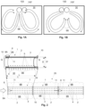
- Fig. 1A and 1B envisages making ducts 100 dedicated to winter ventilation and ducts 100' dedicated to summer ventilation.
- flow diverters positioned upstream the ducts, it is possible to choose in which ducts the air has to pass through depending on the season, bypassing the other ducts.
- This solution is mainly used in large environments such as shopping centers or production factories. This solution involves a duplication of costs and two ducts are required for each room, one of which is always not in use.
- Document DE3303987 describes a solution in which all the holes have the same shape and size that when they're totally overlapped, deliver an air flow having a first volumetric flow rate, while, when they're partially overlapped, they deliver an air flow having a volumetric flow rate lower than the first one, and, if they do not overlap, they do not deliver any air flow.
- a first object of the present invention is to solve the aforementioned drawbacks of the prior art by means of an air duct comprising a tube comprising a first plurality of holes for diffusing an air flow flowing through the duct into an environment ; and a shutter coaxial with respect to the tube comprising at least a second plurality of holes.
- an actuator is configured to move the shutter relative to the pipe to align or misalign at least part of the first plurality of holes with the at least one second plurality of holes.
- Some holes in the duct can therefore be completely open, as in a traditional ventilation duct, and some holes can be partially or totally blocked to vary the flow of air passing through them.
- the ventilation of the environment can therefore be customized according to the temperature required in the environment. Where the shutter partially covers all the holes in the tube, the air leaving the duct coincides with the air passing through the holes in the shutter.
- the holes of the second plurality of holes can be equal to or larger than the holes of the first plurality of holes. In this way, when the holes of the first and second plurality of holes are aligned, the air that comes out of the duct is the same that passes through the holes in the tube.
- the holes of the third plurality of holes of the shutter can be smaller than the holes of the first plurality of holes of the tube. In this way, the alignment of the first and third plurality of holes generates a partialization of the air flows leaving the duct.
- the second and third plurality of holes can have the same shape but different size. This allows to uniform air flowing out of the tube holes. Equal shapes of the holes in fact allow to avoid non-uniformity of the air flows along the edge of the holes of the second and third plurality of holes, in particular with respect to holes that overlap only partially.
- the shutter can have a cylindrical shape.
- said cylindrical shape can have a diameter slightly different from that of the tube so as to slide on the tube.
- the shutter has a slightly larger or slightly smaller diameter than the diameter of the tube, the sliding of the shutter on the tube is allowed without the shutter getting stuck or impinging on the tube.
- the shutter can assume one or more operating positions.
- the actuator can be configured to make the shutter slide longitudinally with respect to the tube.
- the longitudinal sliding of the shutter with respect to the tube reduces the probability of jamming of the shutter since the cylindrical shutter has a greater longitudinal compressive stiffness than its torsional stiffness.
- the shutter can have a longitudinal length shorter than that of the tube. In this way, the shutter can slide with respect to the tube, otherwise if the shutter had a length equal to or greater than the tube, the sliding would be constrained by the elements arranged upstream and downstream of the duct.
- the actuator can be configured to rotate the shutter relative to the tube.
- This version of the duct can be more comfortable and effective for short ducts, i.e. less than or equal to one and a half meters in length. In fact, if the duct is not very long, the risk of the shutter twisting decreases.
- the shutter can be arranged inside the tube.
- the optimal placement of the shutter is inside the duct, as the air pressure forces the shutter itself to adhere to the tube, minimizing losses through the portion between the tube and the shutter.
- the duct can comprise two flanges arranged at the ends of the duct so as to form a gap with the tube within which the shutter moves. These two flanges are arranged at the ends of the duct and are shaped in such a way as to form two portions with the tube which, if seen in section, have the shape of a circular crown within which the shutter slides. These portions act as a guide for the shutter and ensure that it does not deform and follows a correct movement.
- a second object of the present invention is an air pipeline comprising a plurality of air ducts according to the first object of the present invention. A set of ducts, according to the first object of the present invention, joined together forms an air pipeline. An air duct is therefore a single section of the air pipeline.
- the air pipeline can comprise a plurality of air ducts comprising two flanges arranged at the ends of the duct so as to form a radial portion with the tube within which the shutter moves.
- This type of pipeline comprises a plurality of ceiling supports connected to the flanges. The flanges of the interconnection elements between contiguous ducts, protrude radially from the tube. It is therefore possible to connect a support to the flange to connect the duct, and therefore the pipeline, to the ceiling of an environment.
- the pipeline can comprise a control unit configured to manage one or more actuators belonging to respective air ducts.
- the control unit allows you to manage and coordinate multiple actuators, or a single actuator that operates all the shutters, so that their movements are optimized to ventilate the environment.
- a third object of the present invention is represented by a method of managing the air flows leaving a pipeline comprising a plurality of air ducts, each comprising a tube having a first plurality of holes and an shutter movable coaxially with respect to a tube comprising at least a second plurality of holes.
- the method comprises the step of moving the shutter of one or more air ducts with respect to the respective tube to align or misalign at least part of the holes of the first plurality of holes of the tube with the holes of the at least second plurality of holes of the shutter.
- HVAC Heating. Ventilation and Air Conditioning
- the step of moving one or more shutters can provide that the shutters are moved so that the sum of the volumetric flow rates leaving the first plurality of holes in the pipeline substantially corresponds to the volumetric flow rate entering the pipeline. In this way, the outcoming air flows are optimized at all times.
- the numerical reference 20 identifies an air pipeline for the transport and distribution of air in a environment 30.
- the pipeline 20 is configured to receive an incoming air flow 9A and to expelling various outcoming air flows 9B through a first plurality of holes 4.
- the air pipeline 20 comprises one or more air ducts 1. By connecting various air ducts 1 together, the air pipeline 20 is obtained.
- air pipeline and “air duct” can be respectively abbreviated as “pipeline” and "duct”.
- the terminology “plurality of holes” can be abbreviated with the term “holes” to simplify the reading of the text.
- Shutter 3 is moved by an actuator 8.
- the actuator 8 in question can be chosen by the expert in the sector from those available in the state of the art.
- the actuator 8 may be an electric linear actuator comprising a stem or arm configured to extend or contract.
- a fixed part 8A of the actuator 8 is connected to the duct 1 while a moving part 8B of the actuator 8 is connected to the shutter 3.
- the tube 2 has a slot 11 within which the moving part 8B of the actuator 8 can move to actuate the shutter 3.
- a flap gasket can be provided inside this slot 11 to minimize air leaks through it.
- the actuator 8 can also be arranged inside the duct (not illustrated embodiment).
- the actuator 8 can also be configured to move two or more shutters 3, as illustrated in the right-hand side of Fig. 2 , in which the shutters 3 of two contiguous ducts 1 are operated by a single actuator 8.
- actuator 8 can be of the double-acting type and the shutters 3 can all move in the same direction or in opposite directions.
- the shutters 3 can be connected to each other.
- the connection in question (not shown) can lie inside the shutters 3 or pass from the outside of the duct 1.
- a bracket is fixed to the shutter 3 which protrudes from the tube 2 through a slot and connects to the adjacent shutter 3 passing through a second slot present on the tube 2 of the adjacent shutter 3.
- the ducts 1 of Fig. 2 comprise flanges 10 which allow two ducts 1 to be connected together.
- the flanges 10 are connected to the tube 2 so as to create, between the tube 2 and the flange 10 itself, a gap G. This gap G prevents the shutter 3 from coming out in a radial or longitudinal direction.
- the flange 10 has a cylindrical portion which penetrates the tube 2 and a disc-shaped portion connected to the cylindrical portion.
- the gap G is a space between the internal surface of the tube 2 and the external surface of the cylindrical portion of the flange 10.
- the longitudinal extension of the cylindrical portion of the flange 10 is a function of the longitudinal travel of the shutter 3.
- Shutter 3 is configured to slide on the internal surface of tube 2 in order to limit losses.
- the shutter 3 is preferably made of a metallic material having a low thickness or with a low friction material such as nylon or PTFE.
- the tube 2 or the shutter 3 may comprise a layer or surface coating of low friction material, on the side where one faces the other.
- the cylindrical portion of the flange 10 may include, on its outer surface, a gasket (not shown) to reduce flow losses between the flange 10 and the shutter 3.
- the internal diameter of the shutter 3 may substantially correspond to the outside diameter of the cylindrical portion of the flange 10.
- the length L of the shutter 3 is shorter than the length L' of the tube 2 to allow a longitudinal movement of the shutter 3 without hitting against the flanges 10.
- the tube 2 can be of the so-called smooth or flat type, i.e. constituted by a sheet metal closed on itself longitudinally, by means of rivets, seaming or welding.
- the tube 2 can be of the spiral type, i.e. wound into a spiral with the longitudinal edges seamed together, like the tubes 2 illustrated in Fig. 13 .
- the shutter 3 comprises a second plurality of holes 5 which is arranged for opening, closing or choking, at least a part of the holes of the first plurality of holes 4 of the tube 2, as better described with reference to Figs. 3- 11 .
- the holes of the second plurality of holes 5 of the shutter 3 are equal to or larger than the holes of the first plurality 5.
- the term greater or equal refers to the fact that the section of the hole of the shutter 3 is greater than or equal to the section of the hole of tube 2.
- the holes of the second plurality 5 are larger than the holes of the third plurality 6.
- the larger holes are used to maximize the flow rate, while the smaller ones to partialize it.
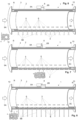
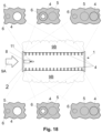
- Figs. 3, 4 and 5 illustrate a first embodiment of duct 1 in which the tube 2 comprises a first plurality of holes 4 inside which a shutter 3 moves longitudinally equipped with a second plurality of holes 5.
- the shutter 3 is moved by a linear actuator 8 equipped with a fixed part 8A connected to tube 2 and a moving part 8B connected to shutter 3.
- Two flanges 10 are fitted to the ends of tube 2 and the shutter 3 slides between the tube 2 and the flanges 10.
- the holes of the first and second plurality of holes 4,5 have the same size.
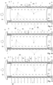
- the operating condition of Fig. 6 corresponds, in terms of result, to that of Fig. 3 , and the holes of the tube 2 are aligned with the holes of the first plurality of holes 5 of the shutter 3. On the contrary, the holes of the third plurality of holes 6 are completely misaligned from those of the first plurality of holes 4 of the tube 2. What has just been said is clear from the detail image at the bottom left of Fig. 6 , in which a total misalignment of the holes 6 and a total alignment of the holes 5 with those 4 of the tube 2 can be noted.
- This condition allows to maximize the outcoming airflows 9B. In this operating position, part of the incoming airflow 9A comes out of the holes of the tube 2 with the outcoming flows 9B and part of the air flow 9C continues towards the next duct 1.
- Fig. 7 corresponds, in terms of result, to that of Fig. 4 , and the holes of the tube 2 are misaligned with respect to the holes of the second and third plurality of holes 5,6.
- the air therefore does not come out of duct 1, but only passes through it.
- the total misalignment of the holes 4 of the tube 2 with the holes 5, 6 of the shutter 3 can be seen in the detail image at the bottom center of Fig. 7 .
- the operating condition of choked outcoming flows 9B is obtained by aligning the holes of the third plurality of holes 6 with the holes of the first plurality of holes 4.
- the holes of the duct 1 are narrower and the outcoming air flows 9B have a lower volumetric flow rate and a higher speed.
- the misalignment of holes 5 with holes 4 of tube 2 and the alignment of holes 6 with holes 4 of tube 2 is better illustrated in the detail image at the bottom left of Fig. 8 .
- the shutter 3 of Fig. 9 allows to simultaneously obtain the first operating position for the holes arranged at the bottom in Fig. 9 and the second operating position for the holes arranged at the top in Fig. 9 .
- This operating condition can also be obtained with a shutter 3 comprising also a third plurality of holes 6.
- a partialization of the outcoming air flows 9B is obtained both on the upper side and on the lower side of the tube 2, as illustrated in Fig.11 . Further intermediate positions allow to progressively increase the outcoming air flows 9B at the bottom to the detriment of those outcoming at the top or vice versa, depending on how the shutter 3 is moved.
- This operating condition can also be obtained with a shutter 3 comprising also a third plurality of holes 6.
- the shutter 3 comprises a second and a third plurality of holes 5,6 and the holes 6 of third plurality are smaller than those of the second plurality of holes 5, it is possible to obtain differentiated flows on two portions of the duct 1, by suitably misaligning of the second plurality of holes 5 with respect to the third plurality of holes 6 on the shutter 3.
- the first plurality of holes 4 is aligned with the second plurality of holes 5 in a portion of the duct 1, in another portion of the duct 1 it is possible that the first plurality of holes 4 is aligned with the third plurality of holes 6, misaligned with the second and third plurality of holes 5,6 or aligned with the second plurality of holes 5.
- first plurality of holes 4 when the first plurality of holes 4 is aligned with the third plurality of holes 5 in a portion of the duct 1, in another portion of the duct 1 it is possible that the first plurality of holes 4 is aligned with the second plurality of holes 5, misaligned with the second and third plurality of holes 5,6 or aligned with the third plurality of holes 6. Finally, when the first plurality of holes 4 is misaligned with the second and third plurality of holes 5 ,6 in a portion of the duct 1, in another portion of the duct 1 it is possible that the first plurality of holes 4 is aligned with the second plurality of holes 5, misaligned with the second and third plurality of holes 5,6 or aligned with the third plurality of holes 6.
- the duct 1 of the third embodiment of Fig. 9-11 is therefore similar to that of the second embodiment of Fig. 6-8 apart from the fact that the tube 2 has a first plurality of holes 4 both on a side and on the other.
- the further difference consists in the fact that the holes of the third plurality of holes 6 of the shutter 3 do not have a smaller section than those of the second plurality of holes 5, but rather have a substantially equal section.
- the holes of the third plurality of holes 6 are slightly offset with respect to those of the second plurality of holes 5, so that the holes 5 and the holes 6 can never be completely aligned simultaneously with the holes of the first plurality of holes 4 of the tube 2. In this way, the effect of closing or choking some holes of the tube 2 and opening or choking others is obtained, modifying the direction and the volumetric flow rate of the outcoming air flows 9B, as shown in Figs. 16, 17 .
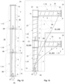
- the duct 1 in one of the embodiments described above or in a variant thereof, can be used to make a pipeline 20 as illustrated in Figs. 12 or 13 .
- the air ducts 1 can be connected to each other in a linear manner, as illustrated in Fig. 12 or have various lateral branches as in Fig. 13 .
- the ducts 1 can have different diameters and can have reducers between one duct and another, when the diameter changes.
- the tubes 2 of the air ducts 1 can be smooth or flat tubes, as shown in Fig. 12 , or spiral tubes, as shown in Fig. 13 .
- the ducts 1 are connected to each other through their flanges 10.
- the flange 10 of a duct 1 is connected to the flange 10 of the adjacent duct 1.
- the flanges 10 can be clamped together via retaining rings.
- the duct 1 are connected to each other via a duct connection 23, such as those in Fig. 13 .
- a duct connection 23 such as those in Fig. 13 .
- the pipeline 20 is closed by a duct cap 24, as illustrated in Fig. 13 .
- the ducts 1 of the pipeline 20 can all be used at the same time or at different times.
- the outcoming air flows 9B are regulated so as to have progressively decreasing air flow rates.
- the amount of air that comes out of the upstream duct 1A is greater than the amount of air that comes out of the downstream air duct 1C.
- the central duct 1B of the pipeline 20 of Fig. 12 can be closed by moving its shutter 3 during a certain period of the year, as happens in the fruit and vegetable department of supermarkets, where in winter it is advisable to interrupt the hot air flow to preserve food.
- the outcoming air flows 9B from the ducts 1A and 1C can also be varied by moving the shutter 3 by means of the control unit 22.
- the control unit 22 is configured to send one or more command signals to the one or more actuators 8, so as to move them in the desired manner.
- Fig. 14 shows the shutter 3 in a first angular position in which some holes of the first plurality of holes 4 of the tube 2 are aligned with all the holes of the second plurality of holes 5 of the shutter 3. In this operating position, the outcoming air flows 9B exit laterally with respect to the duct 1 (hot season).
Landscapes
- Engineering & Computer Science (AREA)
- Chemical & Material Sciences (AREA)
- Combustion & Propulsion (AREA)
- Mechanical Engineering (AREA)
- General Engineering & Computer Science (AREA)
- Air-Flow Control Members (AREA)
- Duct Arrangements (AREA)
Claims (14)
- Luftkanal (1) umfassend:- ein Rohr (2), das eine erste Vielzahl von Löchern (4) zum Diffusionieren von Luft in eine Umgebung (30) umfasst;- einen Verschluss (3), der koaxial zum Rohr (2) angeordnet ist und mindestens eine zweite Vielzahl von Löchern (5) umfasst;- einen Aktuator (8), der dazu konfiguriert ist, den Verschluss (3) relativ zum Rohr (2) zu bewegen, um zumindest einen Teil der ersten Vielzahl von Löchern (4) mit der zweiten Vielzahl von Löchern (5) auszurichten oder zu verstellen;- zwei Flansche (10), die an den Enden des Rohrs (2) angeordnet sind, dadurch gekennzeichnet, dass die beiden Flansche (10) so angeordnet sind, dass sie mit dem Rohr (2) einen Raum (R) bilden, in dem sich der Verschluss (3) bewegen kann.
- Luftkanal (1) nach Anspruch 1, wobei die Löcher der zweiten Lochanzahl (5) gleich groß oder größer als die Löcher der ersten Lochanzahl (4) sind.
- Luftkanal (1) nach Anspruch 2, wobei die erste Vielzahl von Löchern (4) und die zweite Vielzahl von Löchern (5) die gleiche Form, aber unterschiedliche Abmessungen aufweisen.
- Luftkanal (1) nach einem der vorhergehenden Ansprüche, wobei der Verschluss (3) eine dritte Vielzahl von Löchern (6) umfasst, wobei die Löcher der zweiten Vielzahl von Löchern (5) größer sind als diejenigen der dritten Vielzahl von Löchern (6).
- Luftkanal (1) nach Anspruch 4, wobei die Löcher der dritten Vielzahl von Löchern (6) der Verschluss (3) kleiner sind als diejenigen der ersten Vielzahl von Löchern (4) des Rohres (1).
- Luftkanal (1) nach Anspruch 4 oder 5, wobei die zweite Vielzahl von Löchern (5) und die dritte Vielzahl von Löchern (6) die gleiche Form, aber unterschiedliche Abmessungen aufweisen.
- Luftkanal (1) nach einem der vorhergehenden Ansprüche, wobei der Verschluss (3) eine zylindrische Form aufweist, vorzugsweise mit einem Durchmesser (D), der sich geringfügig vom Durchmesser (D') des Rohrs (2) unterscheidet, um auf dem Rohr (2) gleiten zu können.
- Luftkanal (1) nach einem der Ansprüche 5 bis 7, wobei der Verschluss (3) dazu ausgebildet ist, eine oder mehrere der folgenden Betriebspositionen einzunehmen:- eine Betriebsposition, in der die zweite Vielzahl von Löchern (5) mit zumindest einem Teil der ersten Vielzahl von Löchern (4) des Rohrs (2) ausgerichtet ist und die dritte Vielzahl von Löchern (6) relativ zu dem zumindest einen Teil der ersten Vielzahl von Löchern (4) des Rohrs (2) versetzt ist, um den Luftstrom (9B) durch den zumindest einen Teil der ersten Vielzahl von Löchern (4) des Rohrs (2) zu maximieren;- eine Betriebsposition, in der die dritte Vielzahl von Löchern (6) mit zumindest einem Teil der ersten Vielzahl von Löchern (4) des Rohrs (2) ausgerichtet ist und die zweite Vielzahl von Löchern (5) relativ zu dem zumindest einen Teil der ersten Vielzahl von Löchern (4) des Rohrs (2) versetzt ist, um den Luftstrom (9B) durch den zumindest einen Teil der ersten Vielzahl von Löchern (4) des Rohrs (2) zu behindern;- eine Betriebsposition, in der die zweite Vielzahl von Löchern (5) und die dritte Vielzahl von Löchern (5) relativ zu zumindest einem Teil der ersten Vielzahl von Löchern (4) des Rohrs (2) versetzt sind, so dass ganze Teile des Verschlusses (3) zumindest einen Teil der ersten Vielzahl von Löchern (4) des Rohrs (2) verschließen.
- Luftkanal (1) nach einem der vorhergehenden Ansprüche, wobei der Aktuator (8) dazu ausgebildet ist, den Verschluss (3) in Längsrichtung relativ zum Rohr (2) zu verschieben, wobei der Verschluss (3) vorzugsweise eine Längslänge (L) aufweist, die kleiner ist als die Länge (L') des Rohrs (2).
- Luftkanal (1) nach einem der Ansprüche 1 bis 8, wobei der Aktuator (8) dazu ausgebildet ist, der Verschluss (3) relativ zum Rohr (2) zu drehen.
- Luftkanal (1) nach einem der vorhergehenden Ansprüche, wobei der Verschluss (3) innerhalb des Rohrs (2) angeordnet ist.
- Luftleitung (20) mit mehreren Luftkanälen (1) nach einem der vorhergehenden Ansprüche.
- Luftleitung (20) mit mehreren Luftkanälen (1) nach Anspruch 10, die mehrere mit den Flanschen (10) verbundene Deckenstützen (21) aufweisen.
- Luftleitung (20) nach Anspruch 12 oder 13, die eine Steuereinheit (22) umfasst, die dazu konfiguriert ist, einen oder mehrere Aktuatoren (8) zu steuern, die zu den jeweiligen Luftkanälen (1) gehören.
Applications Claiming Priority (1)
| Application Number | Priority Date | Filing Date | Title |
|---|---|---|---|
| IT202200010745 | 2022-05-24 |
Publications (3)
| Publication Number | Publication Date |
|---|---|
| EP4283209A1 EP4283209A1 (de) | 2023-11-29 |
| EP4283209C0 EP4283209C0 (de) | 2025-07-02 |
| EP4283209B1 true EP4283209B1 (de) | 2025-07-02 |
Family
ID=82943317
Family Applications (1)
| Application Number | Title | Priority Date | Filing Date |
|---|---|---|---|
| EP23020236.8A Active EP4283209B1 (de) | 2022-05-24 | 2023-05-20 | Luftkanal mit löchern variabler geometrie und zugehörige rohrleitung |
Country Status (2)
| Country | Link |
|---|---|
| EP (1) | EP4283209B1 (de) |
| ES (1) | ES3037992T3 (de) |
Family Cites Families (8)
| Publication number | Priority date | Publication date | Assignee | Title |
|---|---|---|---|---|
| US2423241A (en) | 1943-06-05 | 1947-07-01 | Anemostat Corp America | Air distributing duct, including a damper means |
| DE3233493A1 (de) * | 1982-09-09 | 1984-03-15 | Emil Dipl.-Ing. Koch (FH), 7300 Esslingen | Kanalsystem fuer lueftungs- und klimaanlagen |
| DE3303987A1 (de) | 1983-02-05 | 1984-08-09 | Emil Dipl.-Ing. Koch (FH), 7300 Esslingen | Kanalsystem insbes. fuer lueftungs- und klimaanlagen |
| US5111739A (en) | 1989-11-13 | 1992-05-12 | Hall James F | Air flow control system |
| SE502954C2 (sv) | 1994-09-14 | 1996-02-26 | Softair Ab | Anordning vid ett tilluftsdon innefattande perforerad cylindermantel |
| FI1883U1 (fi) | 1995-02-17 | 1995-04-27 | Markku Varunki | Anlaeggning foer reglering av luftstroemmar |
| ITMI20110319U1 (it) | 2011-10-11 | 2013-04-12 | Marco Zambolin | Impianto per il trattamento di aria, in particolare per il condizionamento di ambienti |
| US9599362B2 (en) | 2015-06-25 | 2017-03-21 | Leiterman And Associates, Inc. | Air duct systems and methods of air flow control |
-
2023
- 2023-05-20 EP EP23020236.8A patent/EP4283209B1/de active Active
- 2023-05-20 ES ES23020236T patent/ES3037992T3/es active Active
Also Published As
| Publication number | Publication date |
|---|---|
| ES3037992T3 (en) | 2025-10-08 |
| EP4283209C0 (de) | 2025-07-02 |
| EP4283209A1 (de) | 2023-11-29 |
Similar Documents
| Publication | Publication Date | Title |
|---|---|---|
| US5615738A (en) | Internal bypass valve for a heat exchanger | |
| US9394813B2 (en) | Exhaust-gas heat exchanger | |
| DK2324318T3 (en) | heat exchanger | |
| EP4150270B1 (de) | Vorrichtung zum spannen von biegsamen luftkanälen während der unterstützung von inneren hvac-komponenten | |
| WO2019017831A1 (en) | COAXIAL FLOW DISTRIBUTION DEVICE | |
| US3367413A (en) | Cooling towers | |
| EP4283209B1 (de) | Luftkanal mit löchern variabler geometrie und zugehörige rohrleitung | |
| WO2018122575A1 (en) | Recirculating vertical wind tunnel with passive cooling | |
| KR101941537B1 (ko) | 공기방향 전환 기능을 갖는 투웨이 댐퍼 | |
| EP0132847B1 (de) | Einrichtung zur Strömungsumlenkung | |
| CN110878962B (zh) | 异向导风结构、空调器及其出风控制方法 | |
| JP2018200159A (ja) | 流量制御装置 | |
| US8869832B2 (en) | Variable resistance device | |
| US12492872B2 (en) | Heat exchange unit | |
| DE2807901C2 (de) | ||
| EP3040668B1 (de) | Wärmeaustauscher für ein lüftungssystem | |
| US6688376B2 (en) | Two port coil capacity modulator | |
| CN117967823B (zh) | 一种紧凑型开度可调通风阀门 | |
| US11326794B2 (en) | Combined economizer and mixer for air handling unit | |
| CN217685997U (zh) | 进出液组件、空调器 | |
| EP3479030B1 (de) | Vorrichtung zur temperaturregelung von wohneinheiten | |
| FI127233B (fi) | Tuloilmaventtiili | |
| US20050189430A1 (en) | Multi-zone integral face bypass coil system | |
| FI80340C (fi) | Stroemningsregulator. | |
| DE102022105290A1 (de) | Drosselelement für ein Rohr |
Legal Events
| Date | Code | Title | Description |
|---|---|---|---|
| PUAI | Public reference made under article 153(3) epc to a published international application that has entered the european phase |
Free format text: ORIGINAL CODE: 0009012 |
|
| STAA | Information on the status of an ep patent application or granted ep patent |
Free format text: STATUS: THE APPLICATION HAS BEEN PUBLISHED |
|
| AK | Designated contracting states |
Kind code of ref document: A1 Designated state(s): AL AT BE BG CH CY CZ DE DK EE ES FI FR GB GR HR HU IE IS IT LI LT LU LV MC ME MK MT NL NO PL PT RO RS SE SI SK SM TR |
|
| RAP3 | Party data changed (applicant data changed or rights of an application transferred) |
Owner name: ZEFFIRO S.R.L. |
|
| STAA | Information on the status of an ep patent application or granted ep patent |
Free format text: STATUS: REQUEST FOR EXAMINATION WAS MADE |
|
| 17P | Request for examination filed |
Effective date: 20240527 |
|
| RBV | Designated contracting states (corrected) |
Designated state(s): AL AT BE BG CH CY CZ DE DK EE ES FI FR GB GR HR HU IE IS IT LI LT LU LV MC ME MK MT NL NO PL PT RO RS SE SI SK SM TR |
|
| GRAP | Despatch of communication of intention to grant a patent |
Free format text: ORIGINAL CODE: EPIDOSNIGR1 |
|
| STAA | Information on the status of an ep patent application or granted ep patent |
Free format text: STATUS: GRANT OF PATENT IS INTENDED |
|
| INTG | Intention to grant announced |
Effective date: 20250402 |
|
| GRAS | Grant fee paid |
Free format text: ORIGINAL CODE: EPIDOSNIGR3 |
|
| GRAA | (expected) grant |
Free format text: ORIGINAL CODE: 0009210 |
|
| STAA | Information on the status of an ep patent application or granted ep patent |
Free format text: STATUS: THE PATENT HAS BEEN GRANTED |
|
| AK | Designated contracting states |
Kind code of ref document: B1 Designated state(s): AL AT BE BG CH CY CZ DE DK EE ES FI FR GB GR HR HU IE IS IT LI LT LU LV MC ME MK MT NL NO PL PT RO RS SE SI SK SM TR |
|
| REG | Reference to a national code |
Ref country code: GB Ref legal event code: FG4D |
|
| REG | Reference to a national code |
Ref country code: CH Ref legal event code: EP |
|
| REG | Reference to a national code |
Ref country code: DE Ref legal event code: R096 Ref document number: 602023004361 Country of ref document: DE |
|
| REG | Reference to a national code |
Ref country code: IE Ref legal event code: FG4D |
|
| U01 | Request for unitary effect filed |
Effective date: 20250717 |
|
| U07 | Unitary effect registered |
Designated state(s): AT BE BG DE DK EE FI FR IT LT LU LV MT NL PT RO SE SI Effective date: 20250725 |
|
| REG | Reference to a national code |
Ref country code: ES Ref legal event code: FG2A Ref document number: 3037992 Country of ref document: ES Kind code of ref document: T3 Effective date: 20251008 |
|
| PG25 | Lapsed in a contracting state [announced via postgrant information from national office to epo] |
Ref country code: IS Free format text: LAPSE BECAUSE OF FAILURE TO SUBMIT A TRANSLATION OF THE DESCRIPTION OR TO PAY THE FEE WITHIN THE PRESCRIBED TIME-LIMIT Effective date: 20251102 |
|
| PG25 | Lapsed in a contracting state [announced via postgrant information from national office to epo] |
Ref country code: NO Free format text: LAPSE BECAUSE OF FAILURE TO SUBMIT A TRANSLATION OF THE DESCRIPTION OR TO PAY THE FEE WITHIN THE PRESCRIBED TIME-LIMIT Effective date: 20251002 |
|
| PG25 | Lapsed in a contracting state [announced via postgrant information from national office to epo] |
Ref country code: HR Free format text: LAPSE BECAUSE OF FAILURE TO SUBMIT A TRANSLATION OF THE DESCRIPTION OR TO PAY THE FEE WITHIN THE PRESCRIBED TIME-LIMIT Effective date: 20250702 |
|
| PG25 | Lapsed in a contracting state [announced via postgrant information from national office to epo] |
Ref country code: GR Free format text: LAPSE BECAUSE OF FAILURE TO SUBMIT A TRANSLATION OF THE DESCRIPTION OR TO PAY THE FEE WITHIN THE PRESCRIBED TIME-LIMIT Effective date: 20251003 |
|
| PG25 | Lapsed in a contracting state [announced via postgrant information from national office to epo] |
Ref country code: CZ Free format text: LAPSE BECAUSE OF FAILURE TO SUBMIT A TRANSLATION OF THE DESCRIPTION OR TO PAY THE FEE WITHIN THE PRESCRIBED TIME-LIMIT Effective date: 20250702 |
|
| PG25 | Lapsed in a contracting state [announced via postgrant information from national office to epo] |
Ref country code: PL Free format text: LAPSE BECAUSE OF FAILURE TO SUBMIT A TRANSLATION OF THE DESCRIPTION OR TO PAY THE FEE WITHIN THE PRESCRIBED TIME-LIMIT Effective date: 20250702 |
|
| PG25 | Lapsed in a contracting state [announced via postgrant information from national office to epo] |
Ref country code: RS Free format text: LAPSE BECAUSE OF FAILURE TO SUBMIT A TRANSLATION OF THE DESCRIPTION OR TO PAY THE FEE WITHIN THE PRESCRIBED TIME-LIMIT Effective date: 20251002 |
|
| REG | Reference to a national code |
Ref country code: CH Ref legal event code: R18 Free format text: ST27 STATUS EVENT CODE: U-0-0-R10-R18 (AS PROVIDED BY THE NATIONAL OFFICE) Effective date: 20260331 |
|
| PG25 | Lapsed in a contracting state [announced via postgrant information from national office to epo] |
Ref country code: SM Free format text: LAPSE BECAUSE OF FAILURE TO SUBMIT A TRANSLATION OF THE DESCRIPTION OR TO PAY THE FEE WITHIN THE PRESCRIBED TIME-LIMIT Effective date: 20250702 |
|
| PG25 | Lapsed in a contracting state [announced via postgrant information from national office to epo] |
Ref country code: SK Free format text: LAPSE BECAUSE OF FAILURE TO SUBMIT A TRANSLATION OF THE DESCRIPTION OR TO PAY THE FEE WITHIN THE PRESCRIBED TIME-LIMIT Effective date: 20250702 |