EP4282471B1 - Fokussierte ultraschallvorrichtung - Google Patents
Fokussierte ultraschallvorrichtung Download PDFInfo
- Publication number
- EP4282471B1 EP4282471B1 EP22904570.3A EP22904570A EP4282471B1 EP 4282471 B1 EP4282471 B1 EP 4282471B1 EP 22904570 A EP22904570 A EP 22904570A EP 4282471 B1 EP4282471 B1 EP 4282471B1
- Authority
- EP
- European Patent Office
- Prior art keywords
- image
- signal
- transducer
- elements
- contact
- Prior art date
- Legal status (The legal status is an assumption and is not a legal conclusion. Google has not performed a legal analysis and makes no representation as to the accuracy of the status listed.)
- Active
Links
Images


Classifications
-
- A—HUMAN NECESSITIES
- A61—MEDICAL OR VETERINARY SCIENCE; HYGIENE
- A61N—ELECTROTHERAPY; MAGNETOTHERAPY; RADIATION THERAPY; ULTRASOUND THERAPY
- A61N7/00—Ultrasound therapy
- A61N7/02—Localised ultrasound hyperthermia
- A61N7/022—Localised ultrasound hyperthermia intracavitary
-
- A—HUMAN NECESSITIES
- A61—MEDICAL OR VETERINARY SCIENCE; HYGIENE
- A61N—ELECTROTHERAPY; MAGNETOTHERAPY; RADIATION THERAPY; ULTRASOUND THERAPY
- A61N7/00—Ultrasound therapy
- A61N7/02—Localised ultrasound hyperthermia
-
- A—HUMAN NECESSITIES
- A61—MEDICAL OR VETERINARY SCIENCE; HYGIENE
- A61N—ELECTROTHERAPY; MAGNETOTHERAPY; RADIATION THERAPY; ULTRASOUND THERAPY
- A61N7/00—Ultrasound therapy
- A61N2007/0052—Ultrasound therapy using the same transducer for therapy and imaging
-
- A—HUMAN NECESSITIES
- A61—MEDICAL OR VETERINARY SCIENCE; HYGIENE
- A61N—ELECTROTHERAPY; MAGNETOTHERAPY; RADIATION THERAPY; ULTRASOUND THERAPY
- A61N7/00—Ultrasound therapy
- A61N2007/0056—Beam shaping elements
-
- A—HUMAN NECESSITIES
- A61—MEDICAL OR VETERINARY SCIENCE; HYGIENE
- A61N—ELECTROTHERAPY; MAGNETOTHERAPY; RADIATION THERAPY; ULTRASOUND THERAPY
- A61N7/00—Ultrasound therapy
- A61N2007/0082—Scanning transducers
Definitions
- the present invention relates to diagnosis and treatment technology using ultrasound, and more particularly, to image scanning and treatment technology using focused ultrasound (FUS) for Image guided treatment.
- FUS focused ultrasound
- Ultrasound signals may be used in the treatment of biological tissues, such as cancer, tumors, lesions, and the like.
- Treatment with ultrasound is a method of treating a lesion by emitting ultrasound signals to the lesion of the human body.
- Ultrasound treatment may cause less trauma of a patient, compared to general surgical treatment or chemotherapy, and realize non-invasive treatment. Examples of the application of ultrasound treatment include liver cancer, bone sarcoma, breast cancer, pancreatic cancer, kidney cancer, soft tissue tumors, pelvic tumors, and the like.
- US 2011/0144544 A1 describes an ultrasound transducer assembly and methods of using.
- US 2019/0184204 A1 describes an ultrasound guided opening of blood-brain barrier.
- US 2014/0316269 A1 describes transducers, systems, and manufacturing techniques for focused ultrasound therapies.
- a focused ultrasound device capable of protecting an image transducer from a therapeutic focused ultrasound (FUS) signal and removing image artifact and an image transducer protection method are proposed.
- FUS therapeutic focused ultrasound
- a focused ultrasound device includes: an ultrasound probe structure including a treatment transducer for transmitting a focused ultrasound signal and an image transducer for transmitting and receiving an ultrasonic image signal, a reception switch for selecting a plurality of first elements among elements of the image transducer as a protection area and deactivating the same, and selecting a plurality of second other elements among the elements of the image transducer as a reception area and activating the same, an image beamformer for forming a reception beam signal by focusing ultrasonic echo signals received from the plurality of second elements, an image generation unit for generating an image for a target area in an object on the basis of the reception beam signal, and a control unit for controlling the selection of the protection area and reception area by means of a reception switch, wherein the plurality of first elements are in a central area of the image transducer in which the focused ultrasound signal reflected from an interface of the ultrasound probe structure to the image transducer is concentrated and the plurality of second elements may be in a peripheral area of the image transducer.
- the protection area may include N elements located at the center of the entire scan lines, and the reception areas may include (the total number of channels-N)/2 elements on each of the left and right sides with respect to a center position of the entire scan lines.
- the focused ultrasound device may further include a control unit configured to select the reception area by means of the reception switch on the basis of the image generated by the image generation unit.
- the control unit may select and combine at least one from four methods including a first method of activating (the total number of channels-N)/2 elements on each of the left and right sides with respect to the center position of the entire scan lines, a second method of activating (the total number of channels-N)/2 elements on each of the left and right sides with respect to the center position of the entire scan lines and controlling a focusing angle, a third method of activating the total number of channels/2 elements on each of the left and right sides with respect to the center position of the entire scan lines, or a fourth method of activating the total number of channels/2 elements on each of the left and right sides with respect to the center position of the entire scan lines and controlling a focusing angle.
- the image transducer may include a protective film configured to protect the protection area of the image transducer, the protective film may include any one of a diffuse reflection material, a reflective material, and an attenuating material, the diffuse reflection material or the reflective material may be any one of a copper foil, an aluminum foil, and a reflective plate made of plastic, and the attenuating material may be any one of natural rubber, latex, and silicone rubber.
- the ultrasound probe structure may further include a column-shaped case and a membrane filled with an ultrasonic transmission medium along the shape of the case.
- the ultrasound probe structure may further include a height adjustment unit configured to adjust a height of the case of the ultrasound probe structure.
- the ultrasound probe structure may further include a plurality of contact sensors configured to detect contact between the ultrasound probe structure and the target object.
- the focused ultrasound device may further include a noise filter configured to filter noise from signals generated from each of the contact sensors, a contact switch configured to select a predetermined contact signal from among a plurality of contact signals from which the noise has been filtered, a signal processing unit configured to perform signal processing on the selected contact signal, and a control unit configured to determine a contact state at each position from the contact signal received from the signal processing unit and control the treatment transducer to transmit a FUS signal on the basis of the contact state.
- a noise filter configured to filter noise from signals generated from each of the contact sensors
- a contact switch configured to select a predetermined contact signal from among a plurality of contact signals from which the noise has been filtered
- a signal processing unit configured to perform signal processing on the selected contact signal
- a control unit configured to determine a contact state at each position from the contact signal received from the signal processing unit and control the treatment transducer to transmit a FUS signal on the basis of the contact state.
- the focused ultrasound device may further include an output unit configured to output a contact state and a contact instruction message to the outside.
- an image transducer may be protected from a therapeutic focused ultrasound (FUS) signal, thereby minimizing damage to the image transducer and image artifact may be removed.
- FUS therapeutic focused ultrasound
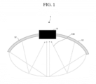
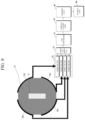
- FIG. 1 is a diagram for explaining a principle in which an image transducer is damaged by a focused ultrasound (FUS) signal in a FUS device according to an embodiment of the present invention.
- FUS focused ultrasound
- the output unit 80 displays menus or information required for ultrasound diagnosis and ultrasound images obtained in the process of ultrasound diagnosis.
- the output unit 550 displays the ultrasound image of the target area inside the object generated by the image generation unit 50.
- the ultrasound image displayed on the output unit 80 may be an A-mode ultrasound image, a B-mode ultrasound image, or a three-dimensional (3D) stereoscopic ultrasound image.
- the output unit 80 may output a contact state between the ultrasound probe structure 10 and the object and a contact instruction message to the outside.
- FIG. 4 is a view illustrating an example of channel activation for protecting a protection area on an entire scan line of an image transducer according to an embodiment of the present invention.
- the four methods include a first method of activating (Ch#-N)/2 elements on each of the left and right sides with respect to the center position of the entire scan lines, a second method of activating (Ch#-N)/2 elements on each of the left and right sides with respect to the center position of the entire scan lines and controlling a focusing angle, a third method of activating Ch#/2 elements on each of the left and right sides with respect to the center position of the entire scan lines, and a fourth method of activating Ch#/2 elements on each of the left and right sides with respect to the center position of the entire scan lines and controlling a focusing angle.
- Ch# represents the total number of channels.
- the control unit 40 may check the resolution of the ultrasound image generated by the image generation unit 50 to determine whether the image transducer 11 is damaged. In this case, when it is determined that the image transducer 11 is damaged based on the deteriorated resolution, the control unit 40 may control the reception switch 21 to select the first method of activating (Ch#-N)/2 elements on each of the left and right sides with respect to the center position of the entire scan lines. Further, the second method of controlling a focusing angle of the reception beam signal may be additionally combined to increase the resolution of the ultrasound image. For example, the control unit 40 may perform spatial compound for focusing the reception beam at different angles, rather than focusing the reception beam in a linear direction. In this case, image noise may be reduced, achieving good contrast and resolution.
- the attenuating material may be, for example, natural rubber, latex, silicone rubber, or the like such that it has a small difference in acoustic impedance from the ultrasonic transmission medium (e.g., water) and can attenuate ultrasound energy.
- the thickness and substance of the attenuating material may be selected in the same way as for the reflective material.
- the ultrasound probe structure 10 may include a column-shaped case 14 and a membrane 13 filled with an ultrasonic transmission medium along the shape of the case 14.
- the case 14 is formed in a vertical direction with respect to a skin surface 63 of the object so that a FUS signal is not reflected.
- the case 14 may be in the form of a sound-absorbing plate.
- the FUS device 1 detects the contact with the object using the plurality of contact sensors 70.
- the FUS device 1 determines the contact state at each position from contact signals detected by means of the plurality of contact sensors 70, and controls the treatment transducer to transmit a FUS signal on the basis of the contact states.
- the FUS device 1 blocks the transmission of the FUS signal of the treatment transducer in the case of incomplete contact, and transmits the FUS signal through the treatment transducer only in the case of complete contact.
- contact signals are detected from a predetermined number or more of the plurality of contact sensors 70, the FUS device 1 determines that the ultrasound probe structure 10 is in contact with the skin surface of the object, and at this time, transmits the FUS signal through the treatment transducer.
- a device configuration for this will be described below with reference to FIG. 9 .
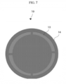
- FIG. 7 is a top view of an ultrasound probe structure including a case and a membrane according to an embodiment of the present invention.
- the ultrasound probe structure 10 includes a column-shaped case 14 and a membrane 13 filled with an ultrasonic transmission medium along the shape of the case 14, and may solve a problem in which a FUS signal is reflected to the image transducer 11 by the case 14.
- FIG. 8 is a bottom view of an ultrasonic probe structure including a plurality of contact sensors according to an embodiment of the present invention.
- the ultrasound probe structure 10 includes a plurality of contact sensors 70.
- the FUS device 1 uses the plurality of contact sensors 70 to determine whether the ultrasound probe structure 10 is in contact with the object, and controls the treatment transducer 12 to transmit a FUS signal only in the case of contact with the object.
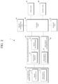
- FIG. 9 is a diagram illustrating the configuration of a FUS device including a plurality of contact sensors according to an embodiment of the present invention.
- the FUS device 1 may include a plurality of contact sensors 70a, 70b, 70c, and 70d, a plurality of noise filters 23, a contact switch 24, a signal processing unit, a control unit 40, and an output unit 80.
- the signal processing unit may include an analog-to-digital (A/D) converter 25 and an amplification unit 26.
- the plurality of noise filters 23, the contact switch 24, and the signal processing unit may be located in the image transmission/reception unit 20 of FIG. 2 .
- the plurality of noise filters 23 filter noise by distinguishing a contact signal and a noise signal from signals generated from each of the contact sensors 70a, 70b, 70c, and 70d.
- the contact switch 24 selects a predetermined contact signal from among a plurality of contact signals from which noise has been filtered by the plurality of noise filters 23 and transmits the selected contact signal to the A/D converter 25.
- the signal processing unit performs signal processing on the contact signal.
- the A/D converter 25 converts an analog signal into a digital signal
- the amplification unit 26 amplifies the digital signal.
- the control unit 40 determines a contact state at each position from the contact signal received from the signal processing unit, and controls the treatment transducer 12 to transmit the FUS signal on the basis of the contact state. For example, as shown in FIG. 9 , when the control unit 40 detects contact signals from three or more (contact rate of 75%) among the four contact sensors 70a, 70b, 70c, and 70d, the control unit 40 determines that the ultrasound probe structure 10 is in contact with the skin surface of the object, and at this time, controls the treatment transducer 12 to transmit the FUS signal. Further, when all four contact sensors 70a, 70b, 70c, and 70d detect contact, the control unit 40 may determine complete contact (contact rate of 100%), and control the treatment transducer 12 to transmit the FUS signal only in the case of complete contact.
- the control unit 40 outputs the contact state to the outside through the output unit 80 when the contact state satisfies a predetermined condition.
- a contact instruction message may be output through the output unit 80 together.
- a contact instruction message may be output through a light-emitting diode (LED), voice, screen, or the like.
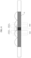
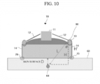
- FIG. 10 is a view illustrating an example of adjusting the height of a case of an ultrasound probe structure according to an embodiment of the present invention.
- a height adjustment unit of the FUS device 1 adjusts the height H' of the case 14 of the ultrasound probe structure 10 to Lcos ⁇ -D.
- L denotes a FUS signal length of the outermost channel of the treatment transducer 12 to the target area 64 of the object
- H denotes a vertical distance from the treatment transducer 12 to the target area 64 of the object
- ⁇ denotes an angle between L and H
- D denotes a vertical distance from the target area 64 of the object to the skin surface 63 of the object
- H' denotes the height of the case 14 of the ultrasound probe structure 10.
- the ultrasonic transmission medium slightly overflows to the top of the membrane 13, as shown by reference numeral 90, so that the FUS device 1 may adjust the amount of ultrasonic transmission medium supplied.
Landscapes
- Health & Medical Sciences (AREA)
- Life Sciences & Earth Sciences (AREA)
- Engineering & Computer Science (AREA)
- Biomedical Technology (AREA)
- Nuclear Medicine, Radiotherapy & Molecular Imaging (AREA)
- Radiology & Medical Imaging (AREA)
- Animal Behavior & Ethology (AREA)
- General Health & Medical Sciences (AREA)
- Public Health (AREA)
- Veterinary Medicine (AREA)
- Pathology (AREA)
- Surgical Instruments (AREA)
- Physics & Mathematics (AREA)
- Biophysics (AREA)
- Heart & Thoracic Surgery (AREA)
- Medical Informatics (AREA)
- Molecular Biology (AREA)
- Surgery (AREA)
- Ultra Sonic Daignosis Equipment (AREA)
- Computer Vision & Pattern Recognition (AREA)
- Gynecology & Obstetrics (AREA)
- Vascular Medicine (AREA)
Claims (11)
- Fokussierte Ultraschallvorrichtung (1), umfassend:eine Ultraschallsondenstruktur (10), die einen Behandlungswandler (12) zum Senden eines fokussierten Ultraschallsignals und einen Bildwandler (11) zum Senden und Empfangen eines Ultraschallbildsignals umfasst;einen Empfangsschalter (21) zum Auswählen und Deaktivieren einer Vielzahl erster Elemente unter den Elementen des Bildwandlers (11) als Schutzbereich (110) und zum Auswählen und Aktivieren einer Vielzahl zweiter anderer Elemente unter den Elementen des Bildwandlers (11) als Empfangsbereich;einen Bildstrahlformer (22) zum Bilden eines Empfangsstrahlsignals durch Fokussieren von Ultraschallechosignalen, die von der Vielzahl von zweiten Elementen empfangen werden;eine Bildgenerierungseinheit (50) zum Generieren eines Bildes für einen Zielbereich (64) in einem Objekt auf der Grundlage des Empfangsstrahlsignals; undeine Steuereinheit (40) zum Steuern der Auswahl des Schutzbereiches (110) und des Empfangsbereiches mittels eines Empfangsschalters (21),dadurch gekennzeichnet, dass sich die Vielzahl der ersten Elemente in einem zentralen Bereich des Bildwandlers (11) befindet, in dem das fokussierte Ultraschallsignal, das von einer Schnittstelle der Ultraschallsondenstruktur (10) zum Bildwandler (11) reflektiert wird, konzentriert ist, und sich die Vielzahl der zweiten Elemente in einem Randbereich des Bildwandlers (11) befindet.
- Fokussierte Ultraschallvorrichtung (1) nach Anspruch 1, wobei der Schutzbereich (110) N Elemente umfasst, die in der Mitte ganzer Abtastzeilen liegen, und der Empfangsbereich (die Gesamtzahl der Kanäle-N)/2 Elemente auf jeder der linken und rechten Seite in Bezug auf eine Mittelposition der ganzen Abtastzeilen umfasst.
- Fokussierte Ultraschallvorrichtung (1) nach Anspruch 1, ferner umfassend eine Steuereinheit (40), die dazu konfiguriert ist, den Empfangsbereich mittels des Empfangsschalters (21) auf der Grundlage des von der Bildgenerierungseinheit (50) generierten Bilds auszuwählen.
- Fokussierte Ultraschallvorrichtung (1) nach Anspruch 3, wobei die Steuereinheit (40) dazu konfiguriert ist, mindestens eines von vier Verfahren auszuwählen und zu kombinieren, beinhaltend ein erstes Verfahren zum Aktivieren von (der Gesamtanzahl der Kanäle-N)/2 Elementen auf jeder der linken und rechten Seite in Bezug auf eine Mittelposition ganzer Abtastzeilen, ein zweites Verfahren zum Aktivieren von (der Gesamtanzahl der Kanäle-N)/2 Elementen auf jeder der linken und rechten Seite in Bezug auf die Mittelposition der ganzen Abtastzeilen und zum Steuern eines Fokussierungswinkels, ein drittes Verfahren zum Aktivieren der Gesamtanzahl der Kanäle/2 Elemente auf jeder der linken und rechten Seite in Bezug auf die Mittelposition der ganzen Abtastzeilen oder ein viertes Verfahren zum Aktivieren der Gesamtanzahl der Kanäle/2 Elemente auf jeder der linken und rechten Seite in Bezug auf die Mittelposition der ganzen Abtastzeilen und zum Steuern eines Fokussierungswinkels.
- Fokussierte Ultraschallvorrichtung (1) nach Anspruch 1, wobei der Bildwandler (11) einen Schutzfilm (500) umfasst, die dazu konfiguriert ist, den Schutzbereich (110) des Bildwandlers (11) zu schützen,der Schutzfilm (500) ein beliebiges von einem diffusen Reflektionsmaterial, einem reflektierenden Material und einem dämpfenden Material umfasst,das diffuse Reflexionsmaterial oder das reflektierende Material eine beliebige von einer Kupferfolie, einer Aluminiumfolie und einer reflektierenden Platte aus Kunststoff ist, unddas dämpfende Material ein beliebiges von Naturkautschuk, Latex und Silikonkautschuk ist.
- Fokussierte Ultraschallvorrichtung (1) nach Anspruch 1, wobei die Ultraschallsondenstruktur (10) ferner ein säulenförmiges Gehäuse (14) und eine Membran (13) umfasst, die entlang der Form des Gehäuses (14) mit einem Ultraschallübertragungsmedium gefüllt ist.
- Fokussierte Ultraschallvorrichtung (1) nach Anspruch 6, wobei die Ultraschallsondenstruktur (10) ferner eine Höheneinstellungseinheit umfasst, die dazu konfiguriert ist, eine Höhe des Gehäuses (14) der Ultraschallsondenstruktur (10) einzustellen.
- Fokussierte Ultraschallvorrichtung (1) nach Anspruch 7, wobei die Höheneinstellungseinheit dazu konfiguriert ist, die Höhe so einzustellen, dass H'=Lcosθ-D erfüllt ist, wobei L eine FUS-Signallänge des äußersten Kanals des Behandlungswandlers (12) zum Zielbereich (64) des Objekts bezeichnet, H einen vertikalen Abstand vom Behandlungswandler (12) zum Zielbereich (64) des Objekts bezeichnet, θ einen Winkel zwischen L und H bezeichnet, D einen vertikalen Abstand vom Zielbereich (64) des Objekts zu einer Hautoberfläche (63) des Objekts bezeichnet und H' die Höhe des Gehäuses (14) der Ultraschallsondenstruktur (10) bezeichnet.
- Fokussierte Ultraschallvorrichtung (1) nach Anspruch 1, wobei die Ultraschallsondenstruktur (10) ferner eine Vielzahl von Kontaktsensoren (70a, 70b, 70c, 70d) umfasst, die dazu konfiguriert sind, einen Kontakt zwischen der Ultraschallsondenstruktur (10) und dem Zielobjekt zu erkennen.
- Fokussierte Ultraschallvorrichtung (1) nach Anspruch 9, ferner umfassend:einen Rauschfilter (23), der dazu konfiguriert ist, Rauschen aus Signalen herauszufiltern, die von jedem der Kontaktsensoren (70a, 70b, 70c, 70d) generiert werden;einen Kontaktschalter (24), der dazu konfiguriert ist, ein vorgegebenes Kontaktsignal aus einer Vielzahl von Kontaktsignalen auszuwählen, aus denen das Rauschen herausgefiltert wurde;eine Signalverarbeitungseinheit, die dazu konfiguriert ist, eine Signalverarbeitung am ausgewählten Kontaktsignal durchzuführen; undeine Steuereinheit (40), die dazu konfiguriert ist, aus dem von der Signalverarbeitungseinheit empfangenen Kontaktsignal an jeder Position einen Kontaktzustand zu bestimmen und den Behandlungswandler (12) so zu steuern, dass er auf der Grundlage des Kontaktzustands ein FUS-Signal sendet.
- Fokussierte Ultraschallvorrichtung (1) nach Anspruch 9, ferner umfassend eine Ausgabeeinheit (80), die dazu konfiguriert ist, einen Kontaktzustand und eine Kontaktanweisungsnachricht nach außen auszugeben.
Applications Claiming Priority (2)
| Application Number | Priority Date | Filing Date | Title |
|---|---|---|---|
| KR1020210175227A KR102486574B1 (ko) | 2021-12-08 | 2021-12-08 | 집속 초음파 장치 및 영상 트랜스듀서 보호 방법 |
| PCT/KR2022/019445 WO2023106740A1 (ko) | 2021-12-08 | 2022-12-02 | 집속 초음파 장치 및 영상 트랜스듀서 보호 방법 |
Publications (4)
| Publication Number | Publication Date |
|---|---|
| EP4282471A1 EP4282471A1 (de) | 2023-11-29 |
| EP4282471A4 EP4282471A4 (de) | 2024-07-24 |
| EP4282471C0 EP4282471C0 (de) | 2025-03-19 |
| EP4282471B1 true EP4282471B1 (de) | 2025-03-19 |
Family
ID=84892486
Family Applications (1)
| Application Number | Title | Priority Date | Filing Date |
|---|---|---|---|
| EP22904570.3A Active EP4282471B1 (de) | 2021-12-08 | 2022-12-02 | Fokussierte ultraschallvorrichtung |
Country Status (5)
| Country | Link |
|---|---|
| US (1) | US12133994B2 (de) |
| EP (1) | EP4282471B1 (de) |
| KR (1) | KR102486574B1 (de) |
| CN (1) | CN116829230A (de) |
| WO (1) | WO2023106740A1 (de) |
Families Citing this family (2)
| Publication number | Priority date | Publication date | Assignee | Title |
|---|---|---|---|---|
| JP7503342B1 (ja) | 2023-07-11 | 2024-06-20 | ソニア・セラピューティクス株式会社 | Hifu照射装置およびその状態を評価する方法 |
| KR20250015266A (ko) * | 2023-07-25 | 2025-02-03 | (주) 레지에나 | 집속 초음파 시술 장치 및 이의 동작 방법 |
Family Cites Families (17)
| Publication number | Priority date | Publication date | Assignee | Title |
|---|---|---|---|---|
| JP2001070333A (ja) * | 1999-09-01 | 2001-03-21 | Toshiba Corp | 超音波照射装置 |
| KR100875208B1 (ko) | 2005-12-09 | 2008-12-19 | 주식회사 메디슨 | 고강도 초점 초음파 시스템 |
| US20090326372A1 (en) * | 2008-06-30 | 2009-12-31 | Darlington Gregory | Compound Imaging with HIFU Transducer and Use of Pseudo 3D Imaging |
| US20110144544A1 (en) | 2009-12-15 | 2011-06-16 | General Electric Company | Ultrasound transducer assembly and methods of using |
| US9456800B2 (en) * | 2009-12-18 | 2016-10-04 | Massachusetts Institute Of Technology | Ultrasound scanning system |
| KR101160958B1 (ko) | 2009-12-29 | 2012-06-29 | 서강대학교산학협력단 | 모델링을 이용한 하이푸 치료 장치, 그 방법 및 기록 매체 |
| EP2397188A1 (de) * | 2010-06-15 | 2011-12-21 | Theraclion SAS | Ultraschallsondenkopf mit einem Bildgebungstransducer mit Abschirmelement |
| KR101398005B1 (ko) | 2011-08-04 | 2014-05-27 | 연세대학교 원주산학협력단 | 소형 치료 초음파 트랜스듀서를 이용한 고강도 집속 초음파 치료 시스템 |
| WO2014081050A1 (ko) * | 2012-11-21 | 2014-05-30 | 알피니언메디칼시스템 주식회사 | 초음파 의료기기에 사용되는 멤브레인 가드, 가이드링, 그를 포함하는 트리트먼트 헤드 |
| CN105188559B (zh) | 2013-02-28 | 2017-09-22 | 爱飞纽医疗机械贸易有限公司 | 检测空化的方法及超声医疗设备 |
| EP2964086A4 (de) * | 2013-03-09 | 2017-02-15 | Kona Medical, Inc. | Wandler, systeme und verfahren für fokussierte ultraschalltherapien |
| WO2014193013A1 (ko) * | 2013-05-31 | 2014-12-04 | 알피니언메디칼시스템 주식회사 | 냉각 기능을 가진 초음파 트랜스듀서 |
| KR20160041516A (ko) * | 2014-10-08 | 2016-04-18 | 삼성전자주식회사 | 빔포밍 장치 및 이를 포함하는 초음파 진단장치 |
| KR101625646B1 (ko) | 2015-08-13 | 2016-05-30 | 알피니언메디칼시스템 주식회사 | 실시간 hifu 치료 모니터링 방법 및 그 초음파 의료 장치 |
| JP7063882B2 (ja) * | 2016-08-01 | 2022-05-09 | コーダンス メディカル インコーポレイテッド | 血液脳関門の超音波ガイド下開放 |
| JP6494591B2 (ja) * | 2016-12-08 | 2019-04-03 | キヤノン株式会社 | 超音波プローブ及び超音波画像取得装置 |
| KR102038425B1 (ko) * | 2017-10-18 | 2019-10-30 | 김동수 | 초음파 피부미용장치 |
-
2021
- 2021-12-08 KR KR1020210175227A patent/KR102486574B1/ko active Active
-
2022
- 2022-12-02 CN CN202280013953.4A patent/CN116829230A/zh active Pending
- 2022-12-02 EP EP22904570.3A patent/EP4282471B1/de active Active
- 2022-12-02 US US18/262,632 patent/US12133994B2/en active Active
- 2022-12-02 WO PCT/KR2022/019445 patent/WO2023106740A1/ko not_active Ceased
Also Published As
| Publication number | Publication date |
|---|---|
| EP4282471C0 (de) | 2025-03-19 |
| CN116829230A (zh) | 2023-09-29 |
| EP4282471A4 (de) | 2024-07-24 |
| US20240075322A1 (en) | 2024-03-07 |
| WO2023106740A1 (ko) | 2023-06-15 |
| KR102486574B1 (ko) | 2023-01-11 |
| US12133994B2 (en) | 2024-11-05 |
| EP4282471A1 (de) | 2023-11-29 |
Similar Documents
| Publication | Publication Date | Title |
|---|---|---|
| US10039938B2 (en) | System and method for variable depth ultrasound treatment | |
| CA3135281C (en) | Ultrasonic imaging device with programmable anatomy and flow imaging | |
| EP4282471B1 (de) | Fokussierte ultraschallvorrichtung | |
| JP2005508667A (ja) | 超音波トランスデューサ | |
| JP7025404B2 (ja) | 表面順応超音波トランスデューサアレイ | |
| US9841404B2 (en) | Probe and manufacturing method thereof | |
| KR102369731B1 (ko) | 프로브 및 프로브의 제조방법 | |
| KR20170087632A (ko) | 초음파 프로브 및 초음파 프로브의 제조 방법 | |
| JP2005169123A (ja) | 2次元配列変換器を用いた容積超音波結像システム | |
| JP4263575B2 (ja) | 超音波送波器及びこれを用いた超音波装置 | |
| KR20200108642A (ko) | 초음파 프로브 및 그 제조 방법 | |
| JP3990208B2 (ja) | 超音波探触子及び超音波診断装置 | |
| JP2024014114A (ja) | 超音波プローブおよび超音波診断装置 | |
| WO2018024501A1 (en) | Surface compliant ultrasound transducer array |
Legal Events
| Date | Code | Title | Description |
|---|---|---|---|
| STAA | Information on the status of an ep patent application or granted ep patent |
Free format text: STATUS: THE INTERNATIONAL PUBLICATION HAS BEEN MADE |
|
| PUAI | Public reference made under article 153(3) epc to a published international application that has entered the european phase |
Free format text: ORIGINAL CODE: 0009012 |
|
| STAA | Information on the status of an ep patent application or granted ep patent |
Free format text: STATUS: REQUEST FOR EXAMINATION WAS MADE |
|
| 17P | Request for examination filed |
Effective date: 20230820 |
|
| AK | Designated contracting states |
Kind code of ref document: A1 Designated state(s): AL AT BE BG CH CY CZ DE DK EE ES FI FR GB GR HR HU IE IS IT LI LT LU LV MC ME MK MT NL NO PL PT RO RS SE SI SK SM TR |
|
| A4 | Supplementary search report drawn up and despatched |
Effective date: 20240626 |
|
| RIC1 | Information provided on ipc code assigned before grant |
Ipc: A61N 7/00 20060101ALI20240620BHEP Ipc: A61B 8/00 20060101ALI20240620BHEP Ipc: A61B 8/08 20060101ALI20240620BHEP Ipc: A61N 7/02 20060101AFI20240620BHEP |
|
| GRAP | Despatch of communication of intention to grant a patent |
Free format text: ORIGINAL CODE: EPIDOSNIGR1 |
|
| STAA | Information on the status of an ep patent application or granted ep patent |
Free format text: STATUS: GRANT OF PATENT IS INTENDED |
|
| DAV | Request for validation of the european patent (deleted) | ||
| DAX | Request for extension of the european patent (deleted) | ||
| INTG | Intention to grant announced |
Effective date: 20241209 |
|
| GRAS | Grant fee paid |
Free format text: ORIGINAL CODE: EPIDOSNIGR3 |
|
| GRAA | (expected) grant |
Free format text: ORIGINAL CODE: 0009210 |
|
| STAA | Information on the status of an ep patent application or granted ep patent |
Free format text: STATUS: THE PATENT HAS BEEN GRANTED |
|
| AK | Designated contracting states |
Kind code of ref document: B1 Designated state(s): AL AT BE BG CH CY CZ DE DK EE ES FI FR GB GR HR HU IE IS IT LI LT LU LV MC ME MK MT NL NO PL PT RO RS SE SI SK SM TR |
|
| REG | Reference to a national code |
Ref country code: GB Ref legal event code: FG4D |
|
| REG | Reference to a national code |
Ref country code: CH Ref legal event code: EP |
|
| REG | Reference to a national code |
Ref country code: IE Ref legal event code: FG4D |
|
| REG | Reference to a national code |
Ref country code: DE Ref legal event code: R096 Ref document number: 602022012078 Country of ref document: DE |
|
| U01 | Request for unitary effect filed |
Effective date: 20250319 |
|
| U07 | Unitary effect registered |
Designated state(s): AT BE BG DE DK EE FI FR IT LT LU LV MT NL PT RO SE SI Effective date: 20250325 |
|
| PG25 | Lapsed in a contracting state [announced via postgrant information from national office to epo] |
Ref country code: RS Free format text: LAPSE BECAUSE OF FAILURE TO SUBMIT A TRANSLATION OF THE DESCRIPTION OR TO PAY THE FEE WITHIN THE PRESCRIBED TIME-LIMIT Effective date: 20250619 |
|
| PG25 | Lapsed in a contracting state [announced via postgrant information from national office to epo] |
Ref country code: NO Free format text: LAPSE BECAUSE OF FAILURE TO SUBMIT A TRANSLATION OF THE DESCRIPTION OR TO PAY THE FEE WITHIN THE PRESCRIBED TIME-LIMIT Effective date: 20250619 |
|
| PG25 | Lapsed in a contracting state [announced via postgrant information from national office to epo] |
Ref country code: HR Free format text: LAPSE BECAUSE OF FAILURE TO SUBMIT A TRANSLATION OF THE DESCRIPTION OR TO PAY THE FEE WITHIN THE PRESCRIBED TIME-LIMIT Effective date: 20250319 |
|
| PG25 | Lapsed in a contracting state [announced via postgrant information from national office to epo] |
Ref country code: GR Free format text: LAPSE BECAUSE OF FAILURE TO SUBMIT A TRANSLATION OF THE DESCRIPTION OR TO PAY THE FEE WITHIN THE PRESCRIBED TIME-LIMIT Effective date: 20250620 |
|
| PG25 | Lapsed in a contracting state [announced via postgrant information from national office to epo] |
Ref country code: SM Free format text: LAPSE BECAUSE OF FAILURE TO SUBMIT A TRANSLATION OF THE DESCRIPTION OR TO PAY THE FEE WITHIN THE PRESCRIBED TIME-LIMIT Effective date: 20250319 |
|
| PG25 | Lapsed in a contracting state [announced via postgrant information from national office to epo] |
Ref country code: ES Free format text: LAPSE BECAUSE OF FAILURE TO SUBMIT A TRANSLATION OF THE DESCRIPTION OR TO PAY THE FEE WITHIN THE PRESCRIBED TIME-LIMIT Effective date: 20250319 |
|
| PG25 | Lapsed in a contracting state [announced via postgrant information from national office to epo] |
Ref country code: PL Free format text: LAPSE BECAUSE OF FAILURE TO SUBMIT A TRANSLATION OF THE DESCRIPTION OR TO PAY THE FEE WITHIN THE PRESCRIBED TIME-LIMIT Effective date: 20250319 |
|
| PG25 | Lapsed in a contracting state [announced via postgrant information from national office to epo] |
Ref country code: CZ Free format text: LAPSE BECAUSE OF FAILURE TO SUBMIT A TRANSLATION OF THE DESCRIPTION OR TO PAY THE FEE WITHIN THE PRESCRIBED TIME-LIMIT Effective date: 20250319 |
|
| PG25 | Lapsed in a contracting state [announced via postgrant information from national office to epo] |
Ref country code: SK Free format text: LAPSE BECAUSE OF FAILURE TO SUBMIT A TRANSLATION OF THE DESCRIPTION OR TO PAY THE FEE WITHIN THE PRESCRIBED TIME-LIMIT Effective date: 20250319 |
|
| PG25 | Lapsed in a contracting state [announced via postgrant information from national office to epo] |
Ref country code: IS Free format text: LAPSE BECAUSE OF FAILURE TO SUBMIT A TRANSLATION OF THE DESCRIPTION OR TO PAY THE FEE WITHIN THE PRESCRIBED TIME-LIMIT Effective date: 20250719 |