EP4281361B1 - Flugzeug mit einziehbaren wirbelgeneratoren - Google Patents
Flugzeug mit einziehbaren wirbelgeneratoren Download PDFInfo
- Publication number
- EP4281361B1 EP4281361B1 EP22700976.8A EP22700976A EP4281361B1 EP 4281361 B1 EP4281361 B1 EP 4281361B1 EP 22700976 A EP22700976 A EP 22700976A EP 4281361 B1 EP4281361 B1 EP 4281361B1
- Authority
- EP
- European Patent Office
- Prior art keywords
- aircraft
- vortex
- vortex generators
- wing
- propeller
- Prior art date
- Legal status (The legal status is an assumption and is not a legal conclusion. Google has not performed a legal analysis and makes no representation as to the accuracy of the status listed.)
- Active
Links
Images


Classifications
-
- B—PERFORMING OPERATIONS; TRANSPORTING
- B64—AIRCRAFT; AVIATION; COSMONAUTICS
- B64C—AEROPLANES; HELICOPTERS
- B64C23/00—Influencing air flow over aircraft surfaces, not otherwise provided for
- B64C23/06—Influencing air flow over aircraft surfaces, not otherwise provided for by generating vortices
-
- B—PERFORMING OPERATIONS; TRANSPORTING
- B64—AIRCRAFT; AVIATION; COSMONAUTICS
- B64C—AEROPLANES; HELICOPTERS
- B64C9/00—Adjustable control surfaces or members, e.g. rudders
- B64C9/34—Adjustable control surfaces or members, e.g. rudders collapsing or retracting against or within other surfaces or other members
-
- B—PERFORMING OPERATIONS; TRANSPORTING
- B64—AIRCRAFT; AVIATION; COSMONAUTICS
- B64C—AEROPLANES; HELICOPTERS
- B64C5/00—Stabilising surfaces
- B64C5/10—Stabilising surfaces adjustable
- B64C5/12—Stabilising surfaces adjustable for retraction against or within fuselage or nacelle
-
- Y—GENERAL TAGGING OF NEW TECHNOLOGICAL DEVELOPMENTS; GENERAL TAGGING OF CROSS-SECTIONAL TECHNOLOGIES SPANNING OVER SEVERAL SECTIONS OF THE IPC; TECHNICAL SUBJECTS COVERED BY FORMER USPC CROSS-REFERENCE ART COLLECTIONS [XRACs] AND DIGESTS
- Y02—TECHNOLOGIES OR APPLICATIONS FOR MITIGATION OR ADAPTATION AGAINST CLIMATE CHANGE
- Y02T—CLIMATE CHANGE MITIGATION TECHNOLOGIES RELATED TO TRANSPORTATION
- Y02T50/00—Aeronautics or air transport
- Y02T50/10—Drag reduction
Definitions
- the invention relates to a fixed-wing aircraft that comprises at least one vortex generator movable through an outer surface of the aircraft between a retracted state and a fully extended state and an electronic control unit adapted to control actuation of the at least one vortex generator.
- the invention also relates to a method for operating a fixed-wing aircraft comprising at least one vortex generator movable between a retracted state and a fully extended state.
- the invention is particularly useful for fixed-wing propeller aircraft, in particular aircraft comprising at least three propeller propulsion units per wing, in particular having electric propulsion units.
- EP 1 896 323 B1 discloses a flow control device comprising: a flow control surface over which fluid is designed to flow in a predetermined direction; vortex generators associated with the flow control surface, each respective vortex generator having a pivot axis that forms an acute angle with respect to the predetermined direction and capable of being positioned in both of an extended state, in which the respective vortex generators function to create a swirling fluid flow, and a retracted state, in which the respective vortex generators are pivoted via the pivot axis so as to lie on top of and in a parallel direction to the overlying flow control surface, and an actuator associated with each of the respective vortex generators, each actuator adapted to state the associated vortex generator between the extended and retracted states.
- US 3,263,945 discloses an aircraft wing comprising a main section and a drooping nose section having a pivotal mounting on the main section, said main section and nose section having respective upper surfaces which possess a substantially continuous common chord line when said sections are in a first positional relationship, said nose section pivoting on said pivotal mounting relative to said main section to a second positional relationship in which said upper surfaces are separated by a gap, at least one sealing plate pivotally mounted on said main section and lying in a retracted state wholly inward of said upper surfaces when said main and nose sections are in said first positional relationship, means moving said sealing plate into said gap to close it when said main and nose sections are brought into said second positional relationship, and a series of blades upstanding on said sealing plate and constituting vortex generators, said blades lying retracted wholly inward of said upper surfaces of said main and nose sections when said sections are in said first positional relationship, and projecting out above said upper surfaces when said sections are in said second positional relationship and the sealing plate is in the gap.
- US 4,039,161 discloses vortex generators connected to a control surface in front of the hinge line of the control surface so that when the control surface is deflected, the vortex generators project into the airstream on the opposite side from the deflecting control surface.
- the action of the vortex generators causes the airflow to remain attached to the control surface at higher angles of attack than would otherwise be possible thus increasing the lift of the air foil and control surface.
- US 5,253,828 discloses a concealable flap actuated vortex generator for generating a vortex on a lifting surface assembly, and an improved aircraft flight-lifting surface having such concealable flap actuated vortex generators.
- the flap of the lifting surface assembly is in the nominal (non-extended or non-deflected) state, the vortex generator is unexposed.
- the flap is actuated by a flap actuator, the flap is extended or deflected from the nominal state, thereby projecting or exposing the vortex generator into an operational state and enabling the generation of a vortex.
- US 8,657,238 B2 discloses a device and methods for low-speed performance improvement of a lifting surface assembly are disclosed. At least one vortex generator is coupled to the lifting surface assembly, and the vortex generator is extended through the lifting surface assembly by drooping a hinged leading coupled to the lifting surface assembly to increase lift. The vortex generator is retracted inside the lifting surface assembly to decrease drag.
- US 10, 202,187 B2 discloses a vortex generator arrangement for an aircraft including a surface section, a flap element pivotable between a first state and a second state, a biasing arrangement biasing the flap element towards the second state, retaining devices retaining the flap element in the first or second state, and a release device releasing the flap element from the first retaining device.
- the biasing arrangement, the first retaining device and the second retaining device are configured such that the second retaining device automatically retains the flap element in the second state after the flap element has been pivoted by the biasing arrangement from the first state into the second state.
- the second retaining device automatically releases the flap element, which pivots against the force of the biasing arrangement into the first state and is automatically retained therein by the first retaining device.
- US 2013/0299643 A1 discloses a vortex generation apparatus including a vortex generator that deploys in response to deployment of a wing leading edge lift augmentation device.
- the vortex generator deploys into a state to generate vortices over a main wing body upper surface region trailing the vortex generator.
- US 2020/0391854 A1 discloses a retractable vortex generator system for an aircraft.
- the system comprises a skin, a slot arranged on the skin, a plate comprising a contour configured for energizing the boundary layer of an air current, and driving means configured for rotating the plate between a first and a second position. In the first position at least part of the contour of the plate protrudes through the slot, and in the second position the plate is retracted within the slot.
- US 2010/0038492 A1 discloses a retractable chine assembly that includes at least one chine which is hingebly mountable to a surface such as of an aircraft having a wing.
- the chine is preferably configured to be movable between stowed and deployed positions.
- the aircraft may include an engine nacelle which may be mounted on an underside of the wing.
- the nacelle may generate a nacelle wake that passes over the wing upper surface at high angles of attack and induces flow separation.
- the chine is preferably configured such that a vortex generated thereby interacts which the nacelle wake to delay flow separation and stall.
- US 2004/0129838 A1 discloses a flow control device and more particularly to reactive modular flow control device with deployable flow effectors. It further relates to a method of operating the flow control device.
- One embodiment includes a method of controlling air flow across a surface of an aircraft under certain flight conditions comprising the steps of sensing fluid separation from the surface by measuring the pressure on the surface; determining a standard deviation of the pressure measurements over a period of time; and deploying a flow effector in response to the standard deviation of the pressure measurements exceeding a predetermined threshold number.
- US 10,137,979 B1 discloses a forebody flow control system and more particularly an aircraft or missile flow control system for enhanced manoeuvrability and stabilization at high angles of attack. It further relates to a method of operating the flow control system.
- it includes a missile or aircraft comprising an afterbody and a forebody; at least one deployable flow effector on the missile or aircraft forebody; at least one sensors each having a signal associated therewith, the at least one sensor being used for determining or estimating flow separation or side forces on the missile forebody; and a closed loop control system; wherein the closed loop control system is used for activating and deactivating the at least one deployable flow effector based on at least in part the signal of the at least one sensor.
- US 3,960,345 discloses a strake, or strakes, or faired simulation of same, mounted on a typical engine nacelle or similar wing mounted body to reduce or prevent the formation of vortices usually occurring with nacelle-wing combinations to improve the lift and drag characteristics of the combination and improve the stability of the aircraft since the undesirable variations of downwash changes over the tail surfaces are reduced or eliminated.
- DE 10 2015 120 958 A1 discloses an actuator module for the controllable generation of turbulence by positioning turbulence surfaces along a surface element has an elongate module base plate and a plurality of two-dimensionally shaped bending actuators.
- Each of the bending actuators comprises a fibre composite panel with shape memory conductors integrated into the fibre composite.
- the fibre composite panel is attached to the module base plate on one attachment side, and the shape memory conductors are designed in such a way that the fibre composite panel extends in the inactive state of the shape memory conductors along the surface of the module base plate and in the active state, starting from the attachment side, curves away from the surface of the module base plate.
- the actuator module includes an arrangement of supply lines extending along the module base plate for electrically activating the bending actuators.
- the object is achieved by fixed-wing aircraft, at least comprising at least one vortex generator movable through an outer surface of the aircraft between a retracted state and a fully extended state by at least one electric motor, this at least one electric motor being exclusively adapted to actuate this at least one vortex generator, and comprising an electronic control unit adapted to control operation of the electric motor for direct actuation of the at least one vortex generator, wherein the actuation of at least one vortex generator is dependent on at least one operation parameter of at least one propeller propulsion unit.
- This aircraft has the advantage that the airflow over a fixed-wing aircraft's outer surface, in particular lifting surface, can be influenced in a particularly flexible manner, thus allowing for a greater degree of flow control.
- the vortex generators When the vortex generators are actuated individually (i.e., independently from other vortex generators) and/or in groups, they can be actuated / moved to a desired deployment state (e.g., retracted, partially extended, or fully extended state, as detailed further below) specifically suited to their local position during the aircraft's current aerodynamic condition while other vortex generators at other positions can be deployed differently.
- the aircraft may, e.g., be a passenger aircraft and/or a cargo aircraft.
- the aircraft may comprise at least one fixed left wing and at least one fixed right wing.
- the aircraft may in particular not be a helicopter.
- the at least one vortex generator In its fully extended state, the at least one vortex generator is maximally extended through the aircraft's surface, thus creating the strongest swirling or turbulence within the air flow.
- the at least one vortex generator In its retracted state, the at least one vortex generator does in particular not extend from the surface but is retracted into or behind the surface. In an embodiment, the retracted vortex generator lays flush with the surface. However, it is generally possible that the vortex generator in its retracted state extends somewhat over the surface, but less than in an extended state.
- the at least one vortex generator may be actuated to at least one intermediate state between the fully extended state and the retracted state, i.e., to at least one partially extended state.
- the partially extended states may be steps of the fully extended state, e.g., 20 %, 40 %, 60 %, 80%.
- the partially extended states may be controlled continuously or quasi-continuously, e.g., in steps of 1% of the fully extended state. This ability may also be expressed such that the vortex generator is differentially extendable.
- the extended state may also be called a deployed state.
- the retracted state may also be called a stowed state.
- the electric motor may be, but is not limited to, a brushless direct current electric (BLDC) motor or a stepper motor.
- the electric motor may be connected to an electrochemical converter (ECC) that generates electrical energy from hydrogen.
- ECC electrochemical converter
- the electric motor may be connected to the electrochemical converter directly or via an electric storage like a battery.
- the electrochemical converter may be connected to a hydrogen tank for supply of hydrogen.
- the electric motor may be directly linked to at least one vortex generator or may be linked via, e.g., a linkage system, a gear system, a vertical lifting device, etc.
- the electrochemical converter may be or comprise at least one fuel cell.
- the electronic control unit is adapted to control operation of an electric motor and thus the actuation of at least one vortex generator driven or actuated by this electric motor. That an electric motor is exclusively used or adapted to actuate at least one vortex generator comprises that the motor is not adapted to actuate a flow control surface of another type (i.e. not a vortex generator) such as a leading or trailing edge control surface like a flap, an aileron etc. Thus, the vortex generators may be actuated independently from an actuation or movement of a flow control surface of another type, if so desired.
- At least one vortex generator of the aircraft is exclusively actuated by operation of an electric motor while at least one other vortex generator of the aircraft is actuated together with a flow control surface. It is thus possible that a subgroup of vortex generators is movable independently from an actuation of a flow control surface of another type while another subgroup of vortex generators is only movable together with an actuation or movement of a flow control surface, e.g. because the movements are mechanically coupled / linked to each other, e.g., because a subgroup of vortex generators and at least one control surface are actuated by the same electric motor or mechanically by the pilot.
- At least one vortex generator may, e.g., be positioned on either side of a lifting surface (e.g., wings / tails), primary and secondary control surfaces (e.g., ailerons / rudders / elevators / flaps), fuselage and / or propulsion system (e.g., pod / engine fairing).
- a lifting surface e.g., wings / tails
- primary and secondary control surfaces e.g., ailerons / rudders / elevators / flaps
- fuselage and / or propulsion system e.g., pod / engine fairing
- the aircraft comprises multiple vortex generators and at least one vortex generator out of these multiple vortex generators is individually actuatable, i.e., extendable and retractable.
- all vortex generators are individually actuatable to have an increased control of the flow over the surface featuring these vortex generators.
- a vortex generator may be associated with a respective electric motor.
- the aircraft comprises multiple vortex generators and at least one set or subgroup comprising at least two vortex generators each out of these multiple vortex generators is actuatable or movable in a similar manner, e.g., as a group.
- the vortex generators of a group may be actuatable by a common motor.
- individually actuatable vortex generators may also be actuated such that they move in a synchronized or group-like manner.
- the individual and/or group-wise actuation of vortex generators includes that, if not actuated, at least two the vortex generators may be in a different deployment state, e.g., retracted, partially extended (to different degrees), or fully extended. Moreover, vortex generators within the same subgroup may be extended to different deployment states using a linkage system.
- the aircraft comprises multiple vortex generators on each lifting surface, in particular on an upper side or surface of a wing. It is an embodiment that the vortex generators of one wing are actuatable independently from the vortex generators of the other wing. This is particularly advantageous when the airflow conditions are different for the different wing, e.g., during a rolling manoeuvre of the aircraft and/or in the presence of shear winds.
- Vortex generators on each lifting surface may be actuated individually, in particular such that at least two vortex generators of one lifting surface are actuatable independently from each other.
- the vortex generators of each lifting surface may be actuated in subgroups. These embodiments are particularly useful when the airflow over the same wing may be significantly different with respect to the position of the vortex generators. This may especially be the case when the wing is equipped with propellers / propeller propulsion units.
- all vortex generators of a wing may be actuated in a similar manner, if so desired, e.g., may all be extended or retracted at the same time.
- the propellers of the propeller propulsion units may be driven by an electrically powered propulsion means (e.g., an electric propulsion motor / electrically powered engine) and/or by a fuel powered propulsion means (e.g., a fuel powered engine like a turboprop aircraft / turbine engine, a piston engine, etc.)
- an electrically powered propulsion means e.g., an electric propulsion motor / electrically powered engine
- a fuel powered propulsion means e.g., a fuel powered engine like a turboprop aircraft / turbine engine, a piston engine, etc.
- multiple propeller propulsion units are attached at each wing and sets / subgroups comprising of at least one vortex generator each are positioned on the wings behind at least two propellers, i.e., at least one set or subgroup comprising at least one vortex generator positioned behind a first propeller and another set or subgroup comprising at least one vortex generator positioned behind a second propeller of the same wing.
- a set of at least one vortex generator is positioned behind each of the propellers of the propeller propulsion units.
- a propeller propulsion unit may comprise at least one propeller and at least one motor, in particular electric motor, to drive the at least one propeller.
- the propeller propulsion unit may further comprise or be connected to an electrochemical converter, ECC, that generates electric energy from hydrogen.
- ECC electrochemical converter
- the propeller propulsion unit may further comprise a hydrogen tank fluidically connected to at least one electrochemical converter. It is thus an embodiment that the aircraft is a hydrogen fuelled, electrically driven aircraft.
- At least one propeller propulsion unit comprises two propellers, e.g., one propeller in front of the wing and one propeller behind / aft the wing or two counterrotating propellers in front of the wing.
- each propeller propulsion unit in particular only creates one propeller slipstream area at the wing.
- the propeller propulsion unit may in particular be mounted to a lower side of a wing, an upper side of a wing or to the tip of the wing.
- the vortex generators of these sets are selectively actuatable between sets, i.e. that vortex generators of one set are actuatable or movable differently from vortex generators of another set. That the vortex generators of these sets are selectively actuatable between sets may also be described such that the vortex generators of a set located in a given propeller slipstream are actuatable or movable differently from other sets located in different propeller slipstreams.
- This gives the advantage that the deployment state of the vortex generators can be matched with characteristics of the individual propeller propulsion units, e.g., their throttle setting or rotation rate (RPM), which may differ between the propeller propulsion units.
- RPM throttle setting or rotation rate
- the alignment of at least one vortex generator of at least one set of vortex generators positioned behind a propeller propulsion unit is angled with respect to the flow direction of a propeller slipstream generated by the propeller / propeller propulsion unit in front.
- a vortex generator may redirect part of the propeller slipstream onto areas of the wing next to a propeller, i.e., to an area not lying in a propeller slipstream / outside of a propeller slipstream, e.g., to an area between two neighbouring propeller propulsion units / propeller slipstreams.
- At least one set comprising at least one vortex generator is positioned on the wings laterally offset / next to the propeller propulsion units and the propellers, respectively, (e.g., in an area not lying in a propeller slipstream) wherein the vortex generators of these sets are actuatable differently to the sets of vortex generators positioned behind the propellers.
- This embodiment gives the advantage that the airflow over the wing may be controlled in a particularly precise manner.
- the deployment of vortex generators that are positioned outside of the propeller slipstream can increase the turbulence / turbidity of the flow to delay the flow separation over regions without the increased dynamic pressure from the propeller slipstream.
- the aircraft may be a distributed electric propulsion (DEP) aircraft in the sense that each wing comprises at least three electrically driven propeller propulsion units per wing, in particular at least three hydrogen fuelled, electrically driven propulsion units.
- DEP distributed electric propulsion
- the flexible (individual and/or group-wise) actuation of the vortex generators is especially useful for this case since the airflow over the wings is particularly irregular along the wing, e.g. as compared to a conventional aircraft having two or less propellers / propeller slipstream areas per wing.
- the actuation of at least one vortex generator is dependent on a flight mode / phase or flight manoeuvre, e.g., whether the aircraft is taking off, climbing, cruising, descending, turning and/or landing.
- the actuation of at least one vortex generator is dependent on the aircraft velocity. This gives the advantage that local flow separation and aerodynamic stalling of the airflow may be delayed at low speeds while excess energy consumption due to aerodynamic drag is reduced at high speeds.
- the actuation of at least one vortex generator is dependent on the aircraft roll angle and/or roll velocity.
- the vortex generators of a wing moving downwards may be actuated differently from the vortex generators of a wing moving upwards.
- One use case is to increase the control authority of a wingtip control surface (e.g., aileron) during a roll manoeuvre, as one wingtip experiences an increase in angle of attack while the other wingtip experiences a decrease in angle of attack depending on whether the vehicle is ascending or descending.
- the actuation of at least one vortex generator is dependent on the sideslip angle of the aircraft.
- Sideslip is the directional angle of the aircraft and occurs when an aircraft is moving sideways as well as forward relative to the oncoming airflow.
- At least one vortex generator may be deployed to increase the directional (yaw) stability and delay the critical angle of directional instability. At best, past this critical angle, the workload for the pilot to control the aircraft significantly increases and at worst the pilot will lose control.
- the actuation of at least one vortex generator is dependent on the angle of attack of the aircraft.
- Angle of attack is the angle between the oncoming airflow and a reference line through the aircraft. As the angle of attack increases, the air flow is more likely to separate from the lifting surfaces, potentially leading to stalling.
- At least one vortex generator may be deployed to re-energise the flow / keep it attached and delay stall.
- the actuation of the at least one vortex generator being dependent on at least one operation parameter of at least one propeller propulsion unit may include the failure of a propeller propulsion unit.
- One use case is to deploy at least one vortex generator to reduce the stall risk of a region over the wing that is located aft of a failed propeller propulsion unit.
- Feathering may mean to set the pitch angle of the propeller blades close to 90 degrees, such that they are close to being parallel with the airflow to minimise drag and prevent unwanted propeller rotation (which is known as windmilling).
- the input power supplied to the propeller propulsion unit particularly comprises input power supplied to a motor/engine which drives the propeller.
- That the actuation of at least one vortex generator is dependent on the propeller rotation direction of at least one propeller propulsion unit may, for example, include the case that if one propeller is rotating counterclockwise, as viewed from behind the propeller, then a vortex generator located near the boundary of the propeller slipstream (but still within the slipstream) where the blade is moving upwards relative to the wing surface can be actuated differently to a vortex generator near the boundary of the propeller slipstream where the blade is moving downwards relative to the wing surface. Then, the actuation of at least one vortex generator is particularly dependent on the relative movement direction of the blades in front of it (e.g., up, down, sideways relative to the vortex generator).
- Swirl recovery is the reduction in rotational induced velocities from the propeller with the purpose to reduce the induced loses of the propeller.
- the swirl distribution is dependent on the propeller rotation direction and through actuating individual vortex generators differently within the propeller slipstream in relation to the propeller rotation direction, the swirl distribution may be controlled. This is particularly useful in the case where the propeller rotation direction is different between adjacent propeller propulsion units.
- the actuation of at least one vortex generator is dependent on the degree of deflection (e.g., a degree of rotation and/or extension) of a control surface, e.g., a flap, an aileron, a rudder, etc.
- the degree of deflection may be detected by a sensor connected to the electronic control unit or may be known from the commands to move the control surface.
- the electronic control unit is connected to at least one sensor and is adapted to operate at least one electric motor for actuation of at least one vortex generator based on sensor readings of the at least one sensor.
- the at least one sensor may be a gyroscope, e.g., to measure the roll and yaw angles or a pitot static probe to determine the aircraft air speed etc.
- the actuation of at least one vortex generator is dependent on a control command from a pilot or from the flight computer.
- a pilot or the flight computer may override the automatic control of the electronic control unit depending on the flight phase / maneuverer or operating mode.
- the pilot may have the ability to select the operating mode of the vortex generators from within the cockpit.
- the actuation may be governed by an actuation logic or actuation scheme in which at least some, possibly all, of the parameter are assigned a unique weight and/or hierarchy determining its influence on the actuation of at least one vortex generator, possibly on the actuation of at least one subgroup or all vortex generators.
- actuation of the at least one of the vortex generator is not limited to or restricted by these parameters.
- the actuation may also be dependent on their position on the aircraft surface: for example, a subgroup of vortex generators near the wingtip may have a higher sensitivity to the roll angle than a subgroup of vortex generators a near the fuselage.
- the object is also achieved by a method for operating a fixed-wing aircraft comprising at least one vortex generator directly movable between a retracted state and an extended state by at least one electric motor, wherein the electric motor is controlled for selective actuation of at least one vortex generator and the actuation of at least one vortex generator is dependent on at least one operation parameter of at least one propulsion unit.
- the method may be embodied in analogy to the aircraft and gives the same advantages.
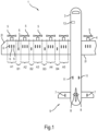
- Fig.1 shows a sketch of an aircraft 1 having a left wing 2l and a right wing 2r (partially shown) fixed to a fuselage 3.
- Each of the wings 2l, 2r is equipped with multiple propeller propulsion units 4 each comprising a propeller 5 on its front.
- Each wing 2l, 2r is further equipped with selectively extendable and retractable vortex generators 6, in particular at different positions along the wings 2l, 2r (not shown for right wing 2r).
- the left wing 2l and the right wing 2r and in particular the vortex generators 6 and their positions may be mirror symmetric with respect to the wings 2l, 2r.
- some of the vortex generators 6 may be positioned in areas A1 to A5 of the upper surface of the wing 2l behind respective propellers 5 thus being exposed to the respective propeller slipstreams.
- Other vortex generators 6 may be positioned in areas B1 to B4 next to the propellers 5, here: in areas B1 to B4 between the propellers 5.
- the aircraft 1 also comprises one or more other selectively extendable and retractable vortex generators, e.g., vortex generators on the underside of the wings 2l, 2r (not shown), vortex generators 7 and 8 at a tail 9 of the aircraft, vortex generators 11 at the fuselage 3 or a fairing, vortex generators at the propeller propulsion units 4 (not shown), etc.
- vortex generators on the underside of the wings 2l, 2r (not shown)
- vortex generators 7 and 8 at a tail 9 of the aircraft
- vortex generators 11 at the fuselage 3 or a fairing vortex generators at the propeller propulsion units 4 (not shown), etc.
- all vortex generators 6 of the left wing 2l and the right wing 2r are individually movable through the upper surface of the respective wing 2l, 2r (i.e., through a respective opening) between a retracted state and a fully extended state, possibly including intermediate / partially extended states.
- the actuation of the vortex generators 6 is caused by operation of respective electric motors 12 (see Fig.2 and Fig.3 ) adapted to exclusively actuate the vortex generators 6. Operation of the electric motors 12 is controlled by an electric control unit 13 of the aircraft 1.
- At least one set or subgroup comprising at least two vortex generators 6 is actuatable in a similar manner.
- the sets of vortex generators 6 in each of the areas A1 to A5 may be actuated in a similar manner / group-wise, wherein the actuation may differ over different sets and areas A1 to A5, respectively.
- the vortex generators 6 for each of the areas A1 to A5 may be actuated together by the same electric motor 12, e.g., the vortex generators 6 of area A1 by a certain common electric motor, the vortex generators 6 of area A2 by another electric motor 12, etc.
- vortex generators 6 of areas B1 to B4 may be actuatable in the same manner or in a different manner as compared to vortex generators 6 of areas A1 to A5 and/or as compared to vortex generators 6 of other areas B1 to B4.
- At least one of the vortex generators 6 of the areas A1 to A5 is angled with respect to the direction of the propeller slipstream, so that part of this airflow is partially redirected to an area B1 to B4.
- the vortex generators 6 of one wing 2l, 2r may be actuatable independently from the vortex generators 6 of the other wing 2r, 2l so that the vortex generators 6 of area A1 of left wing 2l and the vortex generators 6 of mirror symmetric area A1 of right wing 2r may be extended in different degrees at the same time, for example, or the vortex generators 6 of area A1 of left wing 2l may be retracted while the vortex generators 6 of area A1 of right wing 2r are at least partially extended, etc.
- Fig.2 shows a cross-sectional side view of a sketch of the wing 2l with an extended vortex generator 6.
- the vortex generator 6 is mechanically linked to an electric motor 12 by a cable 13, in the present example via a lift enhancer in form of a lever 14 and a barrel 15, alternatively via a linkage (not shown).
- the extended state may be the "normal" state that the vortex generator 6 will move to without external force. This may be achieved by springs etc. (not shown).
- the electric motor 12 only actuates at least one vortex generator 6.
- Fig.3 shows a cross-sectional side view of a sketch of the wing 2l with a retracted vortex generator 6.
- the electric motor 12 moves the lever 14 which, in turn, pulls the cable 13 that, in turn, pulls the vortex generator 6 into the wing 2l.
- the retracted vortex generator 6 may be flush with the surrounding surface of the wing 2l or may still protrude from the surrounding surface, but less than if in a fully extended state.
- the vortex generators 6 shown in Fig.2 and Fig.3 are actuatable independently from the movement and/or positional state of other flow control surfaces 16 or 17 (see Fig.4 to Fig.6 ), e.g. leading and/or trailing edge control surfaces, e.g. slats, flaps, ailerons, etc.
- Fig.4 shows an oblique view of a section of wing 2l with three sets of vortex generators 6, namely a first set S1 of four vortex generators 6 positioned in an area A1 behind a propeller 5, a second set S2 of two vortex generators 6 positioned in an area B1 between two propellers 5, and a third set S3 of three vortex generators 6 in an area A2 behind a propeller 5.
- the vortex generators 6 of each set S1, S2, and S3, respectively may be actuatable or movable in the same manner.
- the vortex generators 6 of set S1 are mechanically linked and thus actuate together with respective trailing edge control surface (e.g., aileron) 16.
- trailing edge control surface e.g., aileron
- the vortex generators 6 of set S3 are mechanically linked and thus actuate together with respective trailing edge control surface 17.
- the vortex generators 6 of set S3 are not mechanically linked with trailing edge control surface (e.g., aileron) 17, and thus do not necessarily (but may) be actuated in combination with the respective control surface 17, e.g. in the manner shown in Fig.2 and Fig.3 , wherein the vortex generators 6 of sets S1 and S3 are moved by actuation of dedicated electric motors 12 dependent on the position (extension / angle of rotation) of the trailing edge control surfaces 16 and 17 as sensed or detected by at least one sensor (not shown) or based on control commands for the trailing edge control surfaces 16 and 17.
- trailing edge control surface e.g., aileron
- the vortex generators 6 of sets S1 and S3 are not mechanically linked with respective trailing edge control surface 16 and 17, respectively.
- the vortex generators 6 of the respective sets S1 and/or S3 may also be extended to different states.
- the vortex generators 6 of set S2 may be independently actuatable from the trailing edge control surfaces 16 and 17 and may, e.g., be differentially extended independent of the extension of retraction of the vortex generators 6 of the sets S1 and S3 (as shown), or may also be fully extended or fully retracted, e.g., depending on the aircraft's 1 manoeuvre.
- the vortex generators 6 may be extended. This is particularly suitable for low-speed scenarios such as take-off and landing, where local flow separation and aerodynamic stall that may occur over the lifting upper surface of the wing 2l is delayed for greater angles of attack. By doing so, the stall speed of the aircraft 1 will be decreased thereby improving the low-speed performance characteristics of the aircraft 1.
- This offers a simpler, lighter, and smoother leading-edge solution when compared to heavier and more complex leading edge high lift devices such as slats or slots that also introduce surface discontinuities.
- the trailing edge control surfaces 16 and 17 are moved into the wing 2l, and the vortex generators 6 are retracted, as shown in Fig.6 .
- the wing surfaces will thus feature smooth low drag flow without the disturbance of deployed vortex generators 6 which would have otherwise transitioned the flow to turbulence.
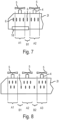
- Fig.7 shows a top-down view of a section of a left wing 2l of the aircraft 1 according to a second exemplary embodiment with areas A1, A2, and B1.
- a control surface in form e.g., an aileron 16 or 17 is shown.
- one of the vortex generators 6 is shown to be positioned next to the area A1 near the wingtip.
- the vortex generators 6 in front of it are also extended. These vortex generators 6 may be extended dependent on the deflection of the aileron 16 or 17, but not mechanically linked to the aileron 16, 17, e.g., as described in conjunction with Fig.2 and Fig.3 . Alternatively, these vortex generators 6 may be mechanically linked to the aileron 16, 17, e.g., as described in conjunction with Fig.4 to Fig.6 .
- Fig.8 shows a top-down view of a section of a left wing 2l of the aircraft 1 according to a third embodiment with areas A1 to A3, and B1 to B2.
- this embodiment there are two rows of vortex generators 6 positioned behind each other at least in the areas A1 to A3.
- the propeller 5 or propeller propulsion unit 4 associated with area A2 has failed.
- the vortex generators 6 of area A2 and possibly also the vortex generators 6 of areas B1 and/or B2 are extended to control the air flow in this area(s) in order to delay the onset of flow separation.
- the other vortex generators 6, e.g., of areas A1 and A3, remain in their deployment state, e.g. a retracted state.
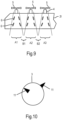
- Fig.9 shows a top-down view of a section of the aircraft's left wing 2l of the aircraft 1 according to a fourth embodiment.
- At least the shown vortex generators 6 of areas A1 to A3 are angled with respect to the axial direction of the propeller slipstream. When extended, they widen the propeller slipstream which then covers an increased area of the wing 2l. This advantageously minimizes the risk of stall in the area that would otherwise not experience any propeller slipstream.
- vortex generators 6, 7 positioned at lifting surfaces, such as the wings 2l, 2r or horizontal elevators of the tail 9, but can also, e.g., be applied to vortex generators 11 at surfaces of the fuselage 3 or fairing, as shown in Fig.10 with a retracted vortex generator 11 on the left side and an extended vortex generator 11 on the right side.
- vortex generators 8 can also, e.g., be applied to vortex generators 11 at surfaces of the fuselage 3 or fairing, as shown in Fig.10 with a retracted vortex generator 11 on the left side and an extended vortex generator 11 on the right side.
- vortex generators 8 can also, e.g., be applied to vortex generators 11 at surfaces of the fuselage 3 or fairing, as shown in Fig.10 with a retracted vortex generator 11 on the left side and an extended vortex generator 11 on the right side.
- vortex generators 8 can also, e.g., be applied to vortex generators 11 at surfaces of
- the actuation of at least one of the vortex generators 6, 7, 8 and/or 11 may be dependent on at least one of the parameters out of the following group of parameters:
- the number, positional arrangement, and orientation of the vortex generators is generally not limited.
- any of the vortex generators 6 shown in the above figures may be present on the same wing 2l, 2r.
- any of the areas A1 to A5 and/or B1 to B4 may comprise one or more rows of vortex generators 6 with none, one or more of the vortex generators 6 being angled with respect to the direction of the propeller slipstream. If there are angled vortex generators 6, they may be actuated independently from non-angled vortex generators 6, and vice-versa, etc.
Landscapes
- Engineering & Computer Science (AREA)
- Aviation & Aerospace Engineering (AREA)
- Toys (AREA)
Claims (13)
- Starrflügelflugzeug (1), mindestens aufweisend:- mindestens einen Wirbelerzeuger (6, 7, 8, 11), der durch eine Außenfläche des Flugzeugs (1) zwischen einem eingefahrenen Zustand und einem vollständig ausgefahrenen Zustand durch mindestens einen Elektromotor (12) bewegbar ist, wobei dieser mindestens eine Elektromotor (12) ausschließlich zum Betätigen dieses mindestens einen Wirbelerzeugers (6, 7, 8, 11) eingerichtet,und dadurch gekennzeichnet, dass es ferner aufweist:- ein elektronisches Steuergerät (13), das zum Steuern des Betriebs des mindestens einen Elektromotors (12) zur Betätigung des mindestens einen Wirbelerzeugers (6, 7, 8, 11) eingerichtet ist,- wobei die Betätigung des mindestens einen Wirbelerzeugers (6, 7, 8, 11) von mindestens einem Betriebsparameter mindestens einer Antriebseinheit (4) abhängig ist.
- Flugzeug (1) nach Anspruch 1, wobei der mindestens eine Betriebsparameter mindestens einen Betriebsparameter aus der folgenden Gruppe von Betriebsparametern umfasst:- Drosseleinstellung;- Propellerdrehzahl;- Propellerdrehrichtung;- Propellerblattverstellwinkel;- Eingangsleistung an eine Antriebseinheit (4).
- Flugzeug (1) nach einem der vorhergehenden Ansprüche, wobei das Flugzeug (1) mehrere Wirbelerzeuger (6, 7, 8, 11) aufweist und mindestens ein Wirbelerzeuger (6, 7, 8, 11) dieser mehreren Wirbelerzeuger (6, 7, 8, 11) einzeln betätigbar ist.
- Flugzeug (1) nach einem der vorhergehenden Ansprüche, wobei das Flugzeug (1) mehrere Wirbelerzeuger (6, 7, 8, 11) aufweist und mindestens ein Satz von mindestens zwei Wirbelerzeugern (6, 7, 8, 11) aus diesen mehreren Wirbelerzeugern (6, 7, 8, 11) auf ähnliche Weise betätigbar ist.
- Flugzeug (1) nach einem der vorhergehenden Ansprüche, wobei das Flugzeug (1) mehrere Wirbelerzeuger (6) an jeder Tragfläche (21, 2r) aufweist.
- Flugzeug (1) nach Anspruch 5, wobei die Wirbelerzeuger (6) der einen Tragfläche (21, 2r) unabhängig von den Wirbelerzeugern (6) der anderen Tragfläche (2r, 21) betätigbar sind.
- Flugzeug (1) nach einem der Ansprüche 5 bis 6, wobei mindestens zwei Wirbelerzeuger (6) einer Tragfläche (21, 2r) unabhängig voneinander betätigbar sind.
- Flugzeug (1) nach einem der Ansprüche 5 bis 7, wobei:- an jeder Tragfläche (21, 2r) mehrere Propellerantriebseinheiten (4) angebracht sind,- Sätze mit jeweils mindestens einem Wirbelerzeuger (6) auf den Tragflächen (21, 2r) hinter mindestens zwei Propellern (5) angeordnet sind, und- die Wirbelerzeuger (6) eines Satzes, der sich in einem bestimmten Propellernachstrom befindet, anders als Sätze betätigbar sind, die sich in anderen Propellernachströmen befinden.
- Flugzeug (1) nach einem der vorhergehenden Ansprüche, wobei eine Ausrichtung mindestens eines Wirbelerzeugers (6) mindestens eines Satzes von Wirbelerzeugern (6), die hinter einem Propeller (5) angeordnet sind, in Bezug auf eine Strömungsrichtung eines Propellernachstroms, der durch den in Front befindlichen Propeller (5) erzeugt wird, abgewinkelt ist.
- Flugzeug (1) nach einem der Ansprüche 8 bis 9, umfassend mindestens einen Satz mit jeweils mindestens einem Wirbelerzeuger (6), der seitlich versetzt zu den Propellern (5) an den Tragflächen (21, 2r) angeordnet ist, wobei die Wirbelerzeuger (6) dieser Sätze anders als die Wirbelerzeuger (6) von hinter den Propellern (5) angeordneten Sätzen betätigbar sind.
- Flugzeug (1) nach einem der Ansprüche 8 bis 10, umfassend mindestens drei Propellerantriebseinheiten (4) pro Tragfläche (2r, 21).
- Flugzeug (1) nach einem der vorhergehenden Ansprüche, wobei die Betätigung mindestens eines Wirbelerzeugers (6, 7, 8, 11) von mindestens einem der Parameter aus der folgenden Gruppe von Parametern abhängig ist:- Flugmodus und/oder Flugmanöver des Flugzeugs (1);- Geschwindigkeit des Flugzeugs (1);- Rollwinkel und/oder Rollgeschwindigkeit des Flugzeugs (1);- Schiebewinkel des Flugzeugs (1);- Anstellwinkel des Flugzeugs (1);- Grad der Auslenkung einer Steuerfläche (16, 17);- Steuerbefehl von einem Piloten oder einem Flugrechner.
- Verfahren zum Betreiben eines Starrflügelflugzeugs (1), umfassend mindestens einen Wirbelerzeuger (6, 7, 8, 11), der durch mindestens einen Elektromotor (12) direkt zwischen einem eingefahrenen Zustand und einem vollständig ausgefahrenen Zustand betätigbar ist, wobei- der Elektromotor (12) ausschließlich zur selektiven Betätigung mindestens eines Wirbelerzeugers (6, 7, 8, 11) gesteuert wird und- die Betätigung mindestens eines Wirbelerzeugers (6, 7, 8, 11) von mindestens einem Betriebsparameter mindestens einer Antriebseinheit (4) abhängig ist.
Applications Claiming Priority (3)
| Application Number | Priority Date | Filing Date | Title |
|---|---|---|---|
| EP21153046.4A EP4032810A1 (de) | 2021-01-22 | 2021-01-22 | Flugzeug mit elektrischem antriebsmodul |
| EP21173058.5A EP4032807B1 (de) | 2021-01-22 | 2021-05-10 | Flugzeug mit einziehbaren wirbelgeneratoren |
| PCT/EP2022/051230 WO2022157243A1 (en) | 2021-01-22 | 2022-01-20 | Aircraft having retractable vortex generators |
Publications (2)
| Publication Number | Publication Date |
|---|---|
| EP4281361A1 EP4281361A1 (de) | 2023-11-29 |
| EP4281361B1 true EP4281361B1 (de) | 2024-10-23 |
Family
ID=80050913
Family Applications (1)
| Application Number | Title | Priority Date | Filing Date |
|---|---|---|---|
| EP22700976.8A Active EP4281361B1 (de) | 2021-01-22 | 2022-01-20 | Flugzeug mit einziehbaren wirbelgeneratoren |
Country Status (3)
| Country | Link |
|---|---|
| US (1) | US12286215B2 (de) |
| EP (1) | EP4281361B1 (de) |
| WO (1) | WO2022157243A1 (de) |
Families Citing this family (1)
| Publication number | Priority date | Publication date | Assignee | Title |
|---|---|---|---|---|
| US12291348B2 (en) * | 2021-01-22 | 2025-05-06 | Blue Spirit Aero Sas | Aircraft propulsion module and aircraft |
Family Cites Families (22)
| Publication number | Priority date | Publication date | Assignee | Title |
|---|---|---|---|---|
| GB1070723A (en) | 1963-01-16 | 1967-06-01 | Dehavilland Aircraft | Improvements in or relating to aircraft |
| US3262945A (en) | 1964-05-14 | 1966-07-26 | Upjohn Co | N-(4-propyl-l-hygroyl) lincosamine phenylosazone |
| US3960345A (en) | 1975-05-16 | 1976-06-01 | Grumman Aerospace Corporation | Means to reduce and/or eliminate vortices, caused by wing body combinations |
| US4039161A (en) | 1975-10-16 | 1977-08-02 | Mcdonnell Douglas Corporation | Hidden vortex generators |
| US5253828A (en) | 1992-07-17 | 1993-10-19 | The Board Of Regents Of The University Of Oklahoma | Concealable flap-actuated vortex generator |
| DE10212036B4 (de) * | 2002-03-19 | 2009-01-02 | Eads Deutschland Gmbh | Verfahren zur Geräuschreduktion für mehrmotorige Propellerflugzeuge |
| US6685143B1 (en) | 2003-01-03 | 2004-02-03 | Orbital Research Inc. | Aircraft and missile forebody flow control device and method of controlling flow |
| US6837465B2 (en) | 2003-01-03 | 2005-01-04 | Orbital Research Inc | Flow control device and method of controlling flow |
| BRPI0613492A2 (pt) | 2005-06-30 | 2011-01-11 | Bell Helicopter Textron Inc | gerador de vórtice retrátil |
| US8087617B2 (en) | 2008-08-15 | 2012-01-03 | The Boeing Company | Retractable nacelle chine |
| US8657238B2 (en) | 2011-07-05 | 2014-02-25 | The Boeing Company | Retractable vortex generator for reducing stall speed |
| US9505485B2 (en) | 2012-05-08 | 2016-11-29 | Lockheed Martin Corporation | Vortex generation |
| DE102015101765A1 (de) | 2015-02-06 | 2016-08-11 | Airbus Operations Gmbh | Vortexgeneratoranordnung |
| DE102015120958A1 (de) | 2015-12-02 | 2017-06-08 | Dg Flugzeugbau Gmbh | Aktives Positionieren von Turbulatorflächenelementen |
| US10889370B2 (en) * | 2018-07-02 | 2021-01-12 | Textron Innovations Inc. | Chord-wise variable vortex generator |
| US11174004B2 (en) * | 2019-05-20 | 2021-11-16 | The Boeing Company | Aircraft nacelles having adjustable chines |
| US11591097B2 (en) * | 2019-05-20 | 2023-02-28 | The Boeing Company | Aircraft nacelles having adjustable chines |
| US11613345B2 (en) * | 2019-05-20 | 2023-03-28 | The Boeing Company | Aircraft nacelles having adjustable chines |
| US11235857B2 (en) * | 2019-05-20 | 2022-02-01 | The Boeing Company | Aircraft nacelles having adjustable chines |
| ES2991416T3 (es) | 2019-06-12 | 2024-12-03 | Airbus Operations Slu | Generador de vórtices de cuchilla |
| US11472546B2 (en) * | 2020-02-24 | 2022-10-18 | Aurora Flight Sciences Corporation | Fixed-wing short-takeoff-and-landing aircraft and related methods |
| US11814154B2 (en) * | 2020-08-31 | 2023-11-14 | General Electric Company | Pitch angles of an aircraft engine rotor assembly |
-
2022
- 2022-01-20 WO PCT/EP2022/051230 patent/WO2022157243A1/en not_active Ceased
- 2022-01-20 US US18/262,269 patent/US12286215B2/en active Active
- 2022-01-20 EP EP22700976.8A patent/EP4281361B1/de active Active
Also Published As
| Publication number | Publication date |
|---|---|
| US12286215B2 (en) | 2025-04-29 |
| US20240076035A1 (en) | 2024-03-07 |
| WO2022157243A1 (en) | 2022-07-28 |
| EP4281361A1 (de) | 2023-11-29 |
Similar Documents
| Publication | Publication Date | Title |
|---|---|---|
| EP4032807B1 (de) | Flugzeug mit einziehbaren wirbelgeneratoren | |
| EP3755622B1 (de) | Starrflügelflugzeug mit nachlaufenden rotoren | |
| EP3000722B1 (de) | Luftfahrzeug | |
| US11787526B2 (en) | System and method for lift augmentation of aircraft wings | |
| US6079672A (en) | Aileron for fixed wing aircraft | |
| US7997538B2 (en) | Aerodynamic fan control effector | |
| US20050242234A1 (en) | Lifters, methods of flight control and maneuver load alleviation | |
| US10926868B1 (en) | Distributed leading-edge lifting surface slat and associated electric ducted fans for fixed lifting surface aircraft | |
| CN101559832A (zh) | 快速远程的混合式直升机 | |
| US9561844B2 (en) | System and method for an air vehicle | |
| WO2022140135A1 (en) | Systems and methods for aircraft lift enhancement | |
| CN116802118A (zh) | 具有可缩回式涡流发生器的飞行器 | |
| US11639217B2 (en) | Procedure for maneuvering a hybrid aerodyne of VTOL or STOL | |
| US20240375780A1 (en) | Aerodynamic lifting structures having embedded engines, and associated systems and methods | |
| US20020047069A1 (en) | Directional control and aerofoil system for aircraft | |
| EP4281361B1 (de) | Flugzeug mit einziehbaren wirbelgeneratoren | |
| US12049299B2 (en) | Airfoil system | |
| US12103672B2 (en) | Rotary wing aircraft with a stabilizer arrangement | |
| GB2634317A (en) | Aircraft wing with leading edge spoiler | |
| KR20230089903A (ko) | 틸트프롭 항공기의 고장 시 비상착륙 방법 | |
| EP4342789B1 (de) | Flugsteuerfläche | |
| GB2345894A (en) | A method of roll control for aeroplanes | |
| WO2025128383A1 (en) | Craft with improved motor pod | |
| Gato et al. | Innovative aerodynamics-The sensible way of restoring growth capability to the EA-6B Prowler | |
| GB2636846A (en) | An aircraft wing with a wing tip device |
Legal Events
| Date | Code | Title | Description |
|---|---|---|---|
| STAA | Information on the status of an ep patent application or granted ep patent |
Free format text: STATUS: UNKNOWN |
|
| STAA | Information on the status of an ep patent application or granted ep patent |
Free format text: STATUS: THE INTERNATIONAL PUBLICATION HAS BEEN MADE |
|
| PUAI | Public reference made under article 153(3) epc to a published international application that has entered the european phase |
Free format text: ORIGINAL CODE: 0009012 |
|
| STAA | Information on the status of an ep patent application or granted ep patent |
Free format text: STATUS: REQUEST FOR EXAMINATION WAS MADE |
|
| 17P | Request for examination filed |
Effective date: 20230817 |
|
| AK | Designated contracting states |
Kind code of ref document: A1 Designated state(s): AL AT BE BG CH CY CZ DE DK EE ES FI FR GB GR HR HU IE IS IT LI LT LU LV MC MK MT NL NO PL PT RO RS SE SI SK SM TR |
|
| DAV | Request for validation of the european patent (deleted) | ||
| DAX | Request for extension of the european patent (deleted) | ||
| GRAP | Despatch of communication of intention to grant a patent |
Free format text: ORIGINAL CODE: EPIDOSNIGR1 |
|
| STAA | Information on the status of an ep patent application or granted ep patent |
Free format text: STATUS: GRANT OF PATENT IS INTENDED |
|
| INTG | Intention to grant announced |
Effective date: 20240626 |
|
| GRAS | Grant fee paid |
Free format text: ORIGINAL CODE: EPIDOSNIGR3 |
|
| GRAA | (expected) grant |
Free format text: ORIGINAL CODE: 0009210 |
|
| STAA | Information on the status of an ep patent application or granted ep patent |
Free format text: STATUS: THE PATENT HAS BEEN GRANTED |
|
| AK | Designated contracting states |
Kind code of ref document: B1 Designated state(s): AL AT BE BG CH CY CZ DE DK EE ES FI FR GB GR HR HU IE IS IT LI LT LU LV MC MK MT NL NO PL PT RO RS SE SI SK SM TR |
|
| REG | Reference to a national code |
Ref country code: GB Ref legal event code: FG4D |
|
| REG | Reference to a national code |
Ref country code: CH Ref legal event code: EP |
|
| REG | Reference to a national code |
Ref country code: DE Ref legal event code: R096 Ref document number: 602022007059 Country of ref document: DE |
|
| REG | Reference to a national code |
Ref country code: IE Ref legal event code: FG4D |
|
| P01 | Opt-out of the competence of the unified patent court (upc) registered |
Free format text: CASE NUMBER: APP_60211/2024 Effective date: 20241107 |
|
| REG | Reference to a national code |
Ref country code: LT Ref legal event code: MG9D |
|
| REG | Reference to a national code |
Ref country code: NL Ref legal event code: MP Effective date: 20241023 |
|
| REG | Reference to a national code |
Ref country code: AT Ref legal event code: MK05 Ref document number: 1734644 Country of ref document: AT Kind code of ref document: T Effective date: 20241023 |
|
| PG25 | Lapsed in a contracting state [announced via postgrant information from national office to epo] |
Ref country code: NL Free format text: LAPSE BECAUSE OF FAILURE TO SUBMIT A TRANSLATION OF THE DESCRIPTION OR TO PAY THE FEE WITHIN THE PRESCRIBED TIME-LIMIT Effective date: 20241023 |
|
| PG25 | Lapsed in a contracting state [announced via postgrant information from national office to epo] |
Ref country code: NL Free format text: LAPSE BECAUSE OF FAILURE TO SUBMIT A TRANSLATION OF THE DESCRIPTION OR TO PAY THE FEE WITHIN THE PRESCRIBED TIME-LIMIT Effective date: 20241023 |
|
| PG25 | Lapsed in a contracting state [announced via postgrant information from national office to epo] |
Ref country code: IS Free format text: LAPSE BECAUSE OF FAILURE TO SUBMIT A TRANSLATION OF THE DESCRIPTION OR TO PAY THE FEE WITHIN THE PRESCRIBED TIME-LIMIT Effective date: 20250223 Ref country code: HR Free format text: LAPSE BECAUSE OF FAILURE TO SUBMIT A TRANSLATION OF THE DESCRIPTION OR TO PAY THE FEE WITHIN THE PRESCRIBED TIME-LIMIT Effective date: 20241023 Ref country code: PT Free format text: LAPSE BECAUSE OF FAILURE TO SUBMIT A TRANSLATION OF THE DESCRIPTION OR TO PAY THE FEE WITHIN THE PRESCRIBED TIME-LIMIT Effective date: 20250224 |
|
| PG25 | Lapsed in a contracting state [announced via postgrant information from national office to epo] |
Ref country code: FI Free format text: LAPSE BECAUSE OF FAILURE TO SUBMIT A TRANSLATION OF THE DESCRIPTION OR TO PAY THE FEE WITHIN THE PRESCRIBED TIME-LIMIT Effective date: 20241023 |
|
| PG25 | Lapsed in a contracting state [announced via postgrant information from national office to epo] |
Ref country code: BG Free format text: LAPSE BECAUSE OF FAILURE TO SUBMIT A TRANSLATION OF THE DESCRIPTION OR TO PAY THE FEE WITHIN THE PRESCRIBED TIME-LIMIT Effective date: 20241023 |
|
| PG25 | Lapsed in a contracting state [announced via postgrant information from national office to epo] |
Ref country code: ES Free format text: LAPSE BECAUSE OF FAILURE TO SUBMIT A TRANSLATION OF THE DESCRIPTION OR TO PAY THE FEE WITHIN THE PRESCRIBED TIME-LIMIT Effective date: 20241023 |
|
| PG25 | Lapsed in a contracting state [announced via postgrant information from national office to epo] |
Ref country code: NO Free format text: LAPSE BECAUSE OF FAILURE TO SUBMIT A TRANSLATION OF THE DESCRIPTION OR TO PAY THE FEE WITHIN THE PRESCRIBED TIME-LIMIT Effective date: 20250123 |
|
| PG25 | Lapsed in a contracting state [announced via postgrant information from national office to epo] |
Ref country code: LV Free format text: LAPSE BECAUSE OF FAILURE TO SUBMIT A TRANSLATION OF THE DESCRIPTION OR TO PAY THE FEE WITHIN THE PRESCRIBED TIME-LIMIT Effective date: 20241023 Ref country code: AT Free format text: LAPSE BECAUSE OF FAILURE TO SUBMIT A TRANSLATION OF THE DESCRIPTION OR TO PAY THE FEE WITHIN THE PRESCRIBED TIME-LIMIT Effective date: 20241023 Ref country code: GR Free format text: LAPSE BECAUSE OF FAILURE TO SUBMIT A TRANSLATION OF THE DESCRIPTION OR TO PAY THE FEE WITHIN THE PRESCRIBED TIME-LIMIT Effective date: 20250124 |
|
| PG25 | Lapsed in a contracting state [announced via postgrant information from national office to epo] |
Ref country code: PL Free format text: LAPSE BECAUSE OF FAILURE TO SUBMIT A TRANSLATION OF THE DESCRIPTION OR TO PAY THE FEE WITHIN THE PRESCRIBED TIME-LIMIT Effective date: 20241023 |
|
| PG25 | Lapsed in a contracting state [announced via postgrant information from national office to epo] |
Ref country code: RS Free format text: LAPSE BECAUSE OF FAILURE TO SUBMIT A TRANSLATION OF THE DESCRIPTION OR TO PAY THE FEE WITHIN THE PRESCRIBED TIME-LIMIT Effective date: 20250123 |
|
| PG25 | Lapsed in a contracting state [announced via postgrant information from national office to epo] |
Ref country code: SM Free format text: LAPSE BECAUSE OF FAILURE TO SUBMIT A TRANSLATION OF THE DESCRIPTION OR TO PAY THE FEE WITHIN THE PRESCRIBED TIME-LIMIT Effective date: 20241023 |
|
| PG25 | Lapsed in a contracting state [announced via postgrant information from national office to epo] |
Ref country code: DK Free format text: LAPSE BECAUSE OF FAILURE TO SUBMIT A TRANSLATION OF THE DESCRIPTION OR TO PAY THE FEE WITHIN THE PRESCRIBED TIME-LIMIT Effective date: 20241023 |
|
| PG25 | Lapsed in a contracting state [announced via postgrant information from national office to epo] |
Ref country code: EE Free format text: LAPSE BECAUSE OF FAILURE TO SUBMIT A TRANSLATION OF THE DESCRIPTION OR TO PAY THE FEE WITHIN THE PRESCRIBED TIME-LIMIT Effective date: 20241023 |
|
| PG25 | Lapsed in a contracting state [announced via postgrant information from national office to epo] |
Ref country code: RO Free format text: LAPSE BECAUSE OF FAILURE TO SUBMIT A TRANSLATION OF THE DESCRIPTION OR TO PAY THE FEE WITHIN THE PRESCRIBED TIME-LIMIT Effective date: 20241023 |
|
| REG | Reference to a national code |
Ref country code: DE Ref legal event code: R097 Ref document number: 602022007059 Country of ref document: DE |
|
| PG25 | Lapsed in a contracting state [announced via postgrant information from national office to epo] |
Ref country code: SK Free format text: LAPSE BECAUSE OF FAILURE TO SUBMIT A TRANSLATION OF THE DESCRIPTION OR TO PAY THE FEE WITHIN THE PRESCRIBED TIME-LIMIT Effective date: 20241023 |
|
| PG25 | Lapsed in a contracting state [announced via postgrant information from national office to epo] |
Ref country code: CZ Free format text: LAPSE BECAUSE OF FAILURE TO SUBMIT A TRANSLATION OF THE DESCRIPTION OR TO PAY THE FEE WITHIN THE PRESCRIBED TIME-LIMIT Effective date: 20241023 |
|
| PG25 | Lapsed in a contracting state [announced via postgrant information from national office to epo] |
Ref country code: IT Free format text: LAPSE BECAUSE OF FAILURE TO SUBMIT A TRANSLATION OF THE DESCRIPTION OR TO PAY THE FEE WITHIN THE PRESCRIBED TIME-LIMIT Effective date: 20241023 |
|
| PLBE | No opposition filed within time limit |
Free format text: ORIGINAL CODE: 0009261 |
|
| REG | Reference to a national code |
Ref country code: CH Ref legal event code: PL |
|
| STAA | Information on the status of an ep patent application or granted ep patent |
Free format text: STATUS: NO OPPOSITION FILED WITHIN TIME LIMIT |
|
| PG25 | Lapsed in a contracting state [announced via postgrant information from national office to epo] |
Ref country code: SE Free format text: LAPSE BECAUSE OF FAILURE TO SUBMIT A TRANSLATION OF THE DESCRIPTION OR TO PAY THE FEE WITHIN THE PRESCRIBED TIME-LIMIT Effective date: 20241023 |
|
| PG25 | Lapsed in a contracting state [announced via postgrant information from national office to epo] |
Ref country code: LU Free format text: LAPSE BECAUSE OF NON-PAYMENT OF DUE FEES Effective date: 20250120 Ref country code: MC Free format text: LAPSE BECAUSE OF FAILURE TO SUBMIT A TRANSLATION OF THE DESCRIPTION OR TO PAY THE FEE WITHIN THE PRESCRIBED TIME-LIMIT Effective date: 20241023 |
|
| 26N | No opposition filed |
Effective date: 20250724 |
|
| REG | Reference to a national code |
Ref country code: DE Ref legal event code: R082 Ref document number: 602022007059 Country of ref document: DE Representative=s name: SCHULZE, MARK, DIPL.-PHYS. DR.RER.NAT., DE |
|
| PG25 | Lapsed in a contracting state [announced via postgrant information from national office to epo] |
Ref country code: BE Free format text: LAPSE BECAUSE OF NON-PAYMENT OF DUE FEES Effective date: 20250131 |
|
| PG25 | Lapsed in a contracting state [announced via postgrant information from national office to epo] |
Ref country code: CH Free format text: LAPSE BECAUSE OF NON-PAYMENT OF DUE FEES Effective date: 20250131 |
|
| REG | Reference to a national code |
Ref country code: BE Ref legal event code: MM Effective date: 20250131 |
|
| PG25 | Lapsed in a contracting state [announced via postgrant information from national office to epo] |
Ref country code: IE Free format text: LAPSE BECAUSE OF NON-PAYMENT OF DUE FEES Effective date: 20250120 |
|
| PGFP | Annual fee paid to national office [announced via postgrant information from national office to epo] |
Ref country code: GB Payment date: 20260219 Year of fee payment: 5 |
|
| PGFP | Annual fee paid to national office [announced via postgrant information from national office to epo] |
Ref country code: DE Payment date: 20260123 Year of fee payment: 5 |
|
| PGFP | Annual fee paid to national office [announced via postgrant information from national office to epo] |
Ref country code: FR Payment date: 20260129 Year of fee payment: 5 |