EP3755622B1 - Starrflügelflugzeug mit nachlaufenden rotoren - Google Patents
Starrflügelflugzeug mit nachlaufenden rotoren Download PDFInfo
- Publication number
- EP3755622B1 EP3755622B1 EP18907259.8A EP18907259A EP3755622B1 EP 3755622 B1 EP3755622 B1 EP 3755622B1 EP 18907259 A EP18907259 A EP 18907259A EP 3755622 B1 EP3755622 B1 EP 3755622B1
- Authority
- EP
- European Patent Office
- Prior art keywords
- rotors
- wing
- tilt
- aircraft
- main wing
- Prior art date
- Legal status (The legal status is an assumption and is not a legal conclusion. Google has not performed a legal analysis and makes no representation as to the accuracy of the status listed.)
- Active
Links
Images


Classifications
-
- B—PERFORMING OPERATIONS; TRANSPORTING
- B64—AIRCRAFT; AVIATION; COSMONAUTICS
- B64C—AEROPLANES; HELICOPTERS
- B64C29/00—Aircraft capable of landing or taking-off vertically, e.g. vertical take-off and landing [VTOL] aircraft
-
- B—PERFORMING OPERATIONS; TRANSPORTING
- B64—AIRCRAFT; AVIATION; COSMONAUTICS
- B64C—AEROPLANES; HELICOPTERS
- B64C29/00—Aircraft capable of landing or taking-off vertically, e.g. vertical take-off and landing [VTOL] aircraft
- B64C29/0008—Aircraft capable of landing or taking-off vertically, e.g. vertical take-off and landing [VTOL] aircraft having its flight directional axis horizontal when grounded
- B64C29/0016—Aircraft capable of landing or taking-off vertically, e.g. vertical take-off and landing [VTOL] aircraft having its flight directional axis horizontal when grounded the lift during taking-off being created by free or ducted propellers or by blowers
- B64C29/0033—Aircraft capable of landing or taking-off vertically, e.g. vertical take-off and landing [VTOL] aircraft having its flight directional axis horizontal when grounded the lift during taking-off being created by free or ducted propellers or by blowers the propellers being tiltable relative to the fuselage
-
- B—PERFORMING OPERATIONS; TRANSPORTING
- B64—AIRCRAFT; AVIATION; COSMONAUTICS
- B64C—AEROPLANES; HELICOPTERS
- B64C27/00—Rotorcraft; Rotors peculiar thereto
- B64C27/22—Compound rotorcraft, i.e. aircraft using in flight the features of both aeroplane and rotorcraft
- B64C27/26—Compound rotorcraft, i.e. aircraft using in flight the features of both aeroplane and rotorcraft characterised by provision of fixed wings
-
- B—PERFORMING OPERATIONS; TRANSPORTING
- B64—AIRCRAFT; AVIATION; COSMONAUTICS
- B64C—AEROPLANES; HELICOPTERS
- B64C27/00—Rotorcraft; Rotors peculiar thereto
- B64C27/22—Compound rotorcraft, i.e. aircraft using in flight the features of both aeroplane and rotorcraft
- B64C27/28—Compound rotorcraft, i.e. aircraft using in flight the features of both aeroplane and rotorcraft with forward-propulsion propellers pivotable to act as lifting rotors
-
- B—PERFORMING OPERATIONS; TRANSPORTING
- B64—AIRCRAFT; AVIATION; COSMONAUTICS
- B64C—AEROPLANES; HELICOPTERS
- B64C27/00—Rotorcraft; Rotors peculiar thereto
- B64C27/52—Tilting of rotor bodily relative to fuselage
-
- B—PERFORMING OPERATIONS; TRANSPORTING
- B64—AIRCRAFT; AVIATION; COSMONAUTICS
- B64C—AEROPLANES; HELICOPTERS
- B64C29/00—Aircraft capable of landing or taking-off vertically, e.g. vertical take-off and landing [VTOL] aircraft
- B64C29/0008—Aircraft capable of landing or taking-off vertically, e.g. vertical take-off and landing [VTOL] aircraft having its flight directional axis horizontal when grounded
- B64C29/0016—Aircraft capable of landing or taking-off vertically, e.g. vertical take-off and landing [VTOL] aircraft having its flight directional axis horizontal when grounded the lift during taking-off being created by free or ducted propellers or by blowers
- B64C29/0025—Aircraft capable of landing or taking-off vertically, e.g. vertical take-off and landing [VTOL] aircraft having its flight directional axis horizontal when grounded the lift during taking-off being created by free or ducted propellers or by blowers the propellers being fixed relative to the fuselage
-
- B—PERFORMING OPERATIONS; TRANSPORTING
- B64—AIRCRAFT; AVIATION; COSMONAUTICS
- B64C—AEROPLANES; HELICOPTERS
- B64C29/00—Aircraft capable of landing or taking-off vertically, e.g. vertical take-off and landing [VTOL] aircraft
- B64C29/02—Aircraft capable of landing or taking-off vertically, e.g. vertical take-off and landing [VTOL] aircraft having its flight directional axis vertical when grounded
-
- B—PERFORMING OPERATIONS; TRANSPORTING
- B64—AIRCRAFT; AVIATION; COSMONAUTICS
- B64C—AEROPLANES; HELICOPTERS
- B64C39/00—Aircraft not otherwise provided for
- B64C39/12—Canard-type aircraft
-
- B—PERFORMING OPERATIONS; TRANSPORTING
- B64—AIRCRAFT; AVIATION; COSMONAUTICS
- B64C—AEROPLANES; HELICOPTERS
- B64C1/00—Fuselages; Constructional features common to fuselages, wings, stabilising surfaces or the like
- B64C2001/0045—Fuselages characterised by special shapes
-
- Y—GENERAL TAGGING OF NEW TECHNOLOGICAL DEVELOPMENTS; GENERAL TAGGING OF CROSS-SECTIONAL TECHNOLOGIES SPANNING OVER SEVERAL SECTIONS OF THE IPC; TECHNICAL SUBJECTS COVERED BY FORMER USPC CROSS-REFERENCE ART COLLECTIONS [XRACs] AND DIGESTS
- Y02—TECHNOLOGIES OR APPLICATIONS FOR MITIGATION OR ADAPTATION AGAINST CLIMATE CHANGE
- Y02T—CLIMATE CHANGE MITIGATION TECHNOLOGIES RELATED TO TRANSPORTATION
- Y02T50/00—Aeronautics or air transport
- Y02T50/10—Drag reduction
Definitions
- New types of aircraft which can take off and land with smaller footprints are being developed. For example, these aircraft may be used in areas where there is no airport or runway.
- Some such aircraft designs have a tilt wing (i.e., a rotatable wing) to which rotors are mounted.
- the tilt wing is in one position (e.g., with the rotors oriented to provide thrust downwards).
- the tilt wing is rotated into another position (e.g., with the rotors oriented to rotate to provide thrust backwards) and the aircraft is able to fly more efficiently in a substantially forward mode or manner.
- the tilt wing is again rotated back into its original position.
- tilt wings can fly, new types of aircraft which (as an example) are more efficient (e.g., which reduces power consumption and/or increases flight range) and/or have higher maximum speeds would be desirable.
- RU 2577931 C1 describes a hybrid short takeoff and landing biplane aircraft, which comprises, mounted on wings thereof, electric and hybrid engine nacelles, each of which comprises four front rotors and two rear screws arranged on all-moving supports and at ends of rotary reduction gears.
- the aircraft also comprises a fuselage, a tail unit, engines parallel-serial hybrid power plant, and power is transmitted to appropriate rotary screws.
- the aircraft also has a main turboprop power unit.
- a first wing of the aircraft is lower than a second, shoulder wing and is mounted in front of second shoulder wing.
- Four smaller rotors, mounted on the second, shoulder wing can be adjusted to different angles.
- US 2015/344134 A1 describes a high performance Vertical Takeoff and Landing (VTOL) aircraft for executing hovering flight, forward flight, and transitioning between the two.
- the VTOL aircraft comprises: (1) a pusher propeller configuration with strategic placement which maximizes the effective use of thrust, (2) four propellers which allow for the highly-controllable and mechanically simple control methods used in multirotor aircraft, (3) electric motors which create mechanically simple, lightweight and reliable operation, (4) and a tandem wing configuration which is stable, controllable and efficient in both hovering and forward flight.
- the VTOL aircraft is capable of full runway, short runway or vertical takeoffs or landings, having unobstructed forward view for camera and sensor placement.
- US 6,561,456 B1 describes an aircraft that is provided having a fuselage and a pair of main wings.
- Each main wing includes a lift fan segment, a generally circular duct defined within the lift fan segment and a fan mounted within the duct.
- a tip extender is coupled with the tip of at least one of the fan blades and contacts the duct sidewall so that flow leakage of air between the tip of the fan and duct sidewall is reduced and the thrust efficiency increased.
- an elongated duct extender is coupled with the wings of the aircraft. When extended, the effective depth of the duct is increased to improve thrust efficiency.
- a number of outlet control vanes are located over the outlet of the duct.
- a pitch control assembly includes a pair of pitch control fans and a pair of canard wings.
- US 3,159,361 A describes an aircraft that comprises a pair of buoyant hulls disposed in spaced parallel side-by-side relation, a pair of substantially identical wings connecting said hulls and adjacent the lower portions thereof, the aerodynamic centres of the wings being spaced at substantially equal distances respectively forwardly and aft of the centre of gravity of the aircraft, and forward thrust producing means mounted on the aircraft above said wings.
- the wings are also buoyant, and have sweep-forward, zero dihedral and positive incidence relative to the hulls, and their trailing edges are level with the underside of the hulls.
- the propulsion engines which may be turbo-prop, or turbojet, are disposed symmetrically about the longitudinal and transverse axes of the aircraft, and are pivotally mounted on struts to provide lifting thrust; their total thrust is preferably greater than the weight of the aircraft to allow for vertical take-off. Trailing edge flaps are provided, operated by jacks through a preloaded compression spring which allows them to yield on hitting an obstruction.
- the aircraft is intended to operate close in the ground cushion, when two of the four engines shown may be shut down, but may fly out of the ground cushion to clear obstacles. Rudders, an elevator, and ailerons are fitted.
- the invention can be implemented in numerous ways, including as a process; an apparatus; a system; a composition of matter; a computer program product embodied on a computer readable storage medium; and/or a processor, such as a processor configured to execute instructions stored on and/or provided by a memory coupled to the processor.
- these implementations, or any other form that the invention may take, may be referred to as techniques.
- the order of the steps of disclosed processes may be altered within the scope of the invention.
- a component such as a processor or a memory described as being configured to perform a task may be implemented as a general component that is temporarily configured to perform the task at a given time or a specific component that is manufactured to perform the task.
- the term 'processor' refers to one or more devices, circuits, and/or processing cores configured to process data, such as computer program instructions.
- the aircraft includes a main wing, where the main wing is a fixed wing, and a main wing rotor that extends outward on a trailing edge side of the main wing where the aircraft is kept at least partially airborne at least some of the time by aerodynamic lift acting on the main wing, and the aircraft is kept at least partially airborne at least some of the time by airflow produced by the main wing rotor.
- the aircraft takes off vertically using the downward thrust from the rotor(s) (e.g., where there is almost no useful lift contribution from the wings) and then transitions to a mostly forward direction of flight (e.g., where all or almost all of the lift to keep the aircraft airborne comes from the wings).
- a mostly forward direction of flight e.g., where all or almost all of the lift to keep the aircraft airborne comes from the wings.
- there is always some combination from both sources e.g., anything from 10% of lift from wing(s) and 90% of lift from rotor(s) to 90% of lift from wing(s) and 10% of lift from rotor(s), or any combination in between).
- the main wing rotor is a tilt rotor that is able to rotate between a first rotor position and a second rotor position.
- the main wing is a forward swept wing and is tapered.
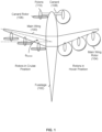
- Figure 1 is a diagram illustrating a top view of a forward swept, fixed wing multicopter with tilt rotors not according to the claimed invention.
- the main wing (100) is a fixed wing which is attached to the fuselage (102) in a fixed manner or position.
- the main wing is not, in other words, a tilt wing which is capable of rotating.
- the main wing (100) is also forward swept (e.g., relative to the pitch axis).
- the forward-sweep angle may be on the order of between 14° and 16° for aircraft with a canard (as shown here) or as high as 35° for aircraft without a canard.
- the main wing (100) has six rotors (104) which are attached to the trailing edge of the main wing.
- these rotors are sometimes referred to as the main wing rotors (e.g., to differentiate them from the rotors which are attached to the canard).
- the number of rotors shown here is merely exemplary and is not intended to be limiting.
- the canard In addition to the six main wing rotors, there are two rotors (106) which are attached to the canard (108). These rotors are sometimes referred to as the canard rotors.
- the canard is thinner than the main wing, so unlike the main wing rotors, the canard rotors are attached to the distal ends of the canard as opposed to the trailing edge of the canard.
- All of the rotors in this example are tilt rotors, meaning that they are capable of tilting or otherwise rotating between two positions.
- the rotors on the left- hand (i.e., port) side of the aircraft are in a cruise (e.g., forward flight, backward facing, etc.) position. See, for example, the position of canard rotor 106. In this position, the rotors are rotating about the (e.g., substantially) longitudinal axes of rotation so that they provide (substantially) backward thrust. When the rotors are in this position, the lift to keep the multicopter airborne comes from the airflow over the main wing (100) and the canard (108).
- the rotational range of a tilt rotor may be as low as 5 degrees or as high as 95 degrees and is design and/or implementation specific.
- the rotors on the right-hand (i.e., starboard) side of the aircraft are in a hover (e.g., vertical takeoff and landing, downward facing, etc.) position. See, for example, the position of main wing rotor 104. In this second position, the rotors are rotating about (e.g., substantially) vertical axes of rotation so that they provide (substantially) downward thrust. In this configuration, the lift to keep the multicopter airborne comes from the downward airflow of the rotors.
- the tilt rotors when oriented to output thrust substantially downward, permit the aircraft to perform vertical takeoff and landings (VTOL).
- This mode or configuration e.g., with respect to the manner in which the aircraft as a whole is flown and/or with respect to the position of the tilt rotors specifically
- hovering The ability to perform vertical takeoffs and landings permits the aircraft to take off and land in areas where there are no airports and/or runways.
- the tilt rotors change position to output thrust (substantially) backwards instead of downwards. This permits the aircraft to fly in a manner that is more efficient for forward flight; this mode or configuration is sometimes referred to as cruising.
- a canard is useful because it can stall first (e.g., before the main wing), creating a lot of pitching moment and not much loss of lift at stall whereas a main wing stall loses a lot of lift per change in pitching moment (e.g., causing the entire aircraft to drop or fall). Stalls are thus potentially more benign with a canard compared to without a canard.
- the canard stall behavior is particularly beneficial in combination with a swept forward wing, as the stall of the main wing can create an adverse pitching moment if at the wing root and can create large and dangerous rolling moments if at the wing tip.
- a canard can create lift at low airspeeds and increase (i.e., maximum lift coefficient) and provides a strut to hold or otherwise attach the canard motors to.
- the pylons (110) which are used to attach the rotors to the canard and/or main wing include some hinge and/or rotating mechanism so that the tilt rotors can rotate between the two positions shown.
- Any appropriate hinge mechanism may be used.
- a lightweight solution may be desirable.
- a fixed-tilt solution may also be used to meet very stringent weight requirements (as will be described in more detail below).
- the aircraft is designed so that the main wing (100) and canard (108) are able to provide sufficient lift to perform a glider-like landing if needed during an emergency.
- some ultralight standards or specifications require the ability to land safely if one or more rotors fail and the ability to perform a glider-like landing would satisfy that requirement.
- One benefit to using a fixed wing for the main wing is that there is no danger of the wing being stuck in the wrong position (e.g., a hover position) where a glider-like landing is not possible because of the wing position which is unsuitable for a glider-like landing.
- a fixed wing with trailing edge mounted tilt rotors Another benefit to a fixed wing with trailing edge mounted tilt rotors is stall behavior (or lack thereof) during a transition from hover position to cruise position or vice versa.
- the tilt wing's angle of attack changes which makes stalling an increased risk.
- a fixed wing with trailing edge mounted tilt rotors does not change the wing angle of attack (e.g., even if rotors are turned off/on or the tilt rotors are shifted).
- this configuration both adds dynamic pressure and circulation over the main wing, which substantially improves the behavior during a transition (e.g., from hover position to cruise position or vice versa).
- the transition can be performed faster and/or more efficiently with a fixed wing with trailing edge mounted tilt rotors compared to a tilt wing (as an example).
- tilt rotors e.g., as opposed to a tilt wing
- a smaller mass fraction is used for the tilt actuator(s). That is, multiple actuators for multiple tilt rotors (still) comprise a smaller mass fraction than a single, heavy actuator for a tilt wing. There are also fewer points of failure with tilt rotors since there are multiple actuators as opposed to a single (and heavy) actuator for the tilt wing.
- a fixed wing makes the transition (e.g., between a cruising mode or position and a hovering mode or position) more stable and/or faster compared to a tilt wing design.
- the rotors are variable pitch propellers which have different blade pitches when the rotors are in the hovering position versus the cruising position.
- different (ranges of) blade pitches may enable more efficient operation or flight when in the cruise position (see, e.g., rotor 106) versus the hovering position (see, e.g., rotor 104).
- rotors are in a cruise position (see, e.g., rotor 106)
- putting the blade pitches into "cruising pitch” e.g., on the order of 26°
- cruising pitch e.g., on the order of 26°
- a hovering pitch e.g., on the order of 6°
- one blade pitch may be well suited for cruising mode but not for hovering mode and vice versa.
- the use of variable pitch propellers enables better (e.g., overall) efficiency, resulting in less power consumption and/or increased flight range.
- Figure 2A is a diagram illustrating a bottom view of of boundary layer thicknesses with the motors off.
- laminar run lines 200a, 202a, and 204a illustrate laminar runs at various regions of the main wing.
- the aircraft is cruising (e.g., flying in a substantially forward direction).
- the main wing rotors (206) are attached to the trailing edge of the main wing (208) example.
- the next figure shows the boundary layer thicknesses with the rotors turned on.
- Figure 2B is a diagram illustrating a bottom view of boundary layer thicknesses with motors on.
- the motors are on and the rotors have an exit airflow velocity of 30 m/s.
- a low pressure region is created towards the aft of the wing which increases the laminar run on the main wing.
- laminar run lines 200b, 202b, and 204b which correspond to laminar run lines 200a, 202a, and 204a from Figure 2A .
- a comparison of the two sets illustrates that the laminar runs have increased for the first two locations (i.e., at 200a/200b and 202a/202b).
- the last location i.e., 204a/204b
- the drag from the main wing rotors (more specifically, the drag from the pylons which are used to attach the main wing rotors to the main wing) is hidden in the wake of the airflow coming off the main wing. See, for example Figure 2A which more clearly shows that the pylons (220) are connected or otherwise attached behind most of the extent of laminar run (222). With the example shown here, the pylons also get to keep some of the boundary layer thickness from the main wing, which means the pylons have lower drag per surface area. This improves the drag compared to some other alternate designs or configurations. The following figures describe this in more detail.
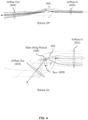
- FIG. 3A is a diagram illustrating an example of a tilt wing configuration not according to the claimed invention with corresponding lift vector, thrust vector, and drag.
- a fixed rotor (300) is attached to a tilt wing (302) at a fixed position or angle. This is one alternate arrangement to the aircraft example(s) described above.
- the tilt wing (302) is rotated. As shown here, with this configuration, there is drag (304) at the trailing edge of the tilt wing, which is undesirable.
- the lift (306) and thrust (308) for this configuration are also shown here, where the tilt wing is shown in the middle of a transition (e.g., between a cruising position and a hovering position). As shown here, the lift (306) and thrust (308) are substantially orthogonal to each other, which is inefficient. In other words, a tilt wing is inefficient during its transition.
- FIG. 3B is a diagram illustrating an example of a fixed wing configuration not according to the claimed invention with a leading edge mounted tilt rotor and corresponding lift vector, thrust vector, and drag.
- a tilt rotor (320) is attached to the leading edge of a fixed wing (322).
- This is another alternate arrangement to the aircraft example(s) described above.
- the corresponding drag (324) and thrust (326) for this arrangement are also shown. There is no useful lift produced with this configuration and therefore no lift vector is shown here.
- FIG. 3C is a diagram illustrating an example of a fixed wing configuration not according to the claimed invention with a trailing edge mounted tilt rotor and corresponding lift vector, thrust vector, and drag.
- the tilt rotor (340) is attached to the trailing edge of the fixed wing (342).
- the drag due to the trailing edge mounted tilt rotor e.g., mostly due to its pylon, not shown
- the drag due to the trailing edge mounted tilt rotor is hidden in the wake of the airflow coming off the main wing.
- there is no drag at least due to the tilt rotor (340)).
- the position of the trailing edge mounted tilt rotor (340) relative to the fixed wing (342) also sucks air (344) over the fixed wing, after which the air turns or bends through the rotor and downwards.
- This flow turning over the wing generates a relatively large induced lift (346) which is shown here.
- the thrust vector (348) due to the rotors is also shown here. It is noted that the induced lift (346) and thrust (348) are substantially in the same direction (i.e., both are pointing substantially upwards) which is a more efficient arrangement, including during a transition.
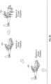
- FIG. 4 is a diagram illustrating an example of airflow produced when trailing edge mounted tilt rotors on a main wing are off.
- a tilt rotor multicopter (400) not according to the claimed invention is shown but with the main wing rotors turned off for comparison purposes.
- the airflow in (402) and the airflow out (404) are moving in substantially the same direction. That is, the airflow does not turn (e.g., downwards) as it passes through the rotors.
- Multicopter 420 shows the same multicopter as multicopter 400 except the rotors are turned on.
- the airflow in (422) and the airflow out (424) have noticeable different directions and there is noticeable turning or bending of the airflow as it passes through the rotors of the exemplary multicopter shown. As described above, this induces a noticeable lift, which is desirable because less power is consumed and/or the range of the multicopter increases.
- the main wing rotors (426) are in the hovering position. As shown here, these rotors are slightly pitched or otherwise angled (e.g., with the tops of the main wing rotors pointing slightly forward and the bottoms pointing slightly backward). In this diagram, the amount of tilting is shown as ⁇ pitch (428) and in some examples is on the order of 90° of rotational range or movement (e.g., ⁇ 3° up from horizontal when in a cruise position (e.g., for minimum drag) and ⁇ 93° degrees down from horizontal when in a hover position which produces a rotational range of -96°).
- ⁇ pitch (428) is on the order of 90° of rotational range or movement (e.g., ⁇ 3° up from horizontal when in a cruise position (e.g., for minimum drag) and ⁇ 93° degrees down from horizontal when in a hover position which produces a rotational range of -96°).
- multicopter 420 is shown in a nose up position and therefore the vertical axis (e.g., relative to the multicopter) is not perpendicular to the ground and/or frame of reference.
- the rotors e.g., the main wing rotors and/or canard rotors
- this roll is on the order of 10° for greater yaw authority.
- the main wing is tapered (e.g., the wing narrows going outward towards the tip) in addition to being forward swept.
- tapered e.g., the wing narrows going outward towards the tip
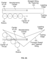
- FIG. 5A is a diagram illustrating an example of a forward swept and tapered wing and a straight wing for comparison.
- wing 500 is a straight wing with no tapering (e.g., the wing is the same width from the center to the tip of the wing).
- Exemplary rotors (502) are shown at the trailing edge of the string wing (500).
- the center of thrust (504), indicated by a dashed and dotted line, is dictated by the placement or arrangement of the rotors and runs through the centers of the main wing rotors (502). For simplicity, the canard rotors are ignored in this example.
- the center of lift is based on the shape of the wing. For a rectangular wing such as wing 500, the center of lift (506), indicated by a solid line, runs down the center of the wing. Calculation of the aerodynamic center is more complicated (e.g., the aerodynamic center depends upon the cross section of the wing, etc.) and aerodynamic center 508, indicated by a dashed line, is exemplary and/or typical for this type of wing.
- the straight wing (500) and its corresponding arrangement of main wing rotors (502) produce a center of thrust (504) which is relatively far from both the center of lift (506) as well as the aerodynamic center.
- This separation is undesirable. More specifically, when the main wing rotors (502) are in hover position, if the center of thrust (504) is far from the center of lift (506), then the transition (e.g., in the context of the movement of the aircraft as a whole, such as switching from flying substantially upwards to substantially forwards or vice versa) would create very large moments and could overturn the vehicle or prevent acceleration or stability and/or or require a massive and/or non-optimal propulsion system. In cruise, if the center of thrust (504) is far from center of lift (506), it not as important (e.g., since the thrust moments are both smaller and more easily balanced by aerodynamic moments), but it is still undesirable.
- the forward swept and tapered wing (520) according to the present invention and its corresponding arrangement of rotors (522) along the trailing edge produce a center of thrust (524), center of lift (526), and aerodynamic center (528) which are closer to each other.
- the forward sweep of the wing brings the rotors forward to varying degrees. This causes the center of thrust to move forward (e.g., towards the leading edge and towards the other centers).
- the tapering of the wings prevents the aerodynamic center and center of lift from creeping forward too much (and more importantly, away from the center of thrust) as a result of the forward sweep.
- the center of thrust would move forward approximately the same amount as the aerodynamic center and center of lift and would result in more separation between the three centers than is shown here with wing 520.
- Some other benefits to a forward swept and tapered wing include better pilot visibility, and a better fuselage junction location with the main wing (e.g., so that the main wing spar can pass behind the pilot seat, not through the pilot). Furthermore, the taper reduces wing moments and puts the center of the thrust of the motors closer to the wing attachment to the fuselage, as referenced about the direction of flight, so there are less moments carried from wing to fuselage, a shorter tail boom (e.g., which reduces the weight of the aircraft), and improved pitch stability.
- Figure 5B is a diagram illustrating an example of a wing configuration not according to the claimed invention with a forward swept, tapered main wing and no canard.
- the main wing (530) is forward swept and tapers (e.g., from the center of the wing to the tip).
- the tips (532) are rounded where the trailing edge follows the shape or contour of the outermost rotor (534) when that rotor is in a hover position as shown here.
- main wing wrap around the front of the rotor e.g., with a relatively small gap between the blades of the rotor and the trailing edge of the main wing
- main wing rotors e.g., including rotor 534 which are attached to the trailing edge of the main wing (530).
- the main wing has more forward sweep than if there was a canard and/or canard rotors.
- the of the leading edge or spar shown here may be on the order of 20° or 30° as opposed to on the order of 10° - 15° when there is a canard and/or canard rotors.
- This type of wing configuration is attractive in applications where sensor placement or other volumetric or structural requirement makes it infeasible to attach a canard to the fuselage forebody area. It also has the fringe benefit of providing additional protection to the pilot compartment in case of a blade-out (e.g., a blade shatters and/or becomes a projectile) even on one of the propellers, since the main wing blocks a substantial portion of the blade's trajectory cone intersecting the cockpit. It also may be beneficial in terms of simplicity and a reduction in the number of components on the system, and can be useful with a different number of rotors on the vehicle, where for packaging reasons a canard is not sensible.
- a blade-out e.g., a blade shatters and/or becomes a projectile
- Figure 5C is a diagram illustrating an example of a wing configuration not according to the claimed invention with a canard and a straight main wing.
- a canard 540
- canard rotors 542
- main wing 544
- main wing 546
- the center of lift, center of thrust, and aerodynamic center may be relatively close to each other with the center of lift and center of thrust in front of the aerodynamic center, all of which are desirable properties or characteristics.
- This type of wing configuration is attractive in applications where wing sweep is unfavorable structurally or from a controls standpoint, or where a compact vehicle footprint is required while increasing the available lift, and where induced drag is not important.
- the additional canard area helps with additional lift availability in forward flight and transition while additional rotors help with an increase in lift during hover.
- Adding additional rotors to the canard instead of the main wing allows the center of thrust to move forward, matching the forward motion of the aerodynamic center due to increase in canard area, provided the canard has a small area
- Increasing canard area allows vehicle span to remain unchanged or smaller compared to increasing lifting surface area by scaling up a large main wing.
- FIG. 5D is a diagram illustrating an example of a tail.
- an aircraft includes a tail (i.e., a tail is not necessary) and this diagram shown one example of a tail.
- the tail (550) has two control surfaces (552) such as flaps.
- a control rotor (554) is attached the trailing edge of the tail at the center of that edge. As shown here, the control rotor may be oriented so that the pushes air downward.
- the control rotor (554) a fixed rotor or a tilt rotor. In some examples not according to the claimed invention, if the control rotor is a tilt rotor, there would be no leading edge rotors (556).
- the tail also includes two tail rotors (556) which are attached to the leading edge of the tail. In some examples, the leading edge rotors (556) are fixed rotors.
- FIG. 5E is a diagram illustrating an example not according to the claimed invention of a pylon which is attached to the top surface of the main wing.
- the main wing rotors 560a/560b
- the pylon in turn, in attached to the top surface of the main wing (564) where there is a gap (566) between the pylon and the main wing.
- offsetting the pylons from the wing's upper surface leads to additional lift and lower drag on the wing surface, at the expense of increased drag on the pylon skin.
- the canard rotors (if there are any) and main wing rotors are tilt rotors and the rotors are able to switch (if desired) between two positions for more efficient flight.
- slow flight e.g., below stall speed for a traditional fixed wing
- the following figures describe exemplary tilt transitions of the rotors between cruise position and hover position.
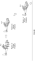
- Figure 6A is a diagram illustrating an example not according to the claimed invention of a takeoff tilt change from hover position to cruise position.
- the exemplary multicopter performs this transition soon after taking off (e.g., substantially vertically). It is noted that this tilt transition is optional and the aircraft may fly entirely with the rotors in the hovering position (albeit with less than optimal performance). For example, this could be done if there is risk in the tilting action, and it would be better to take the action at a higher altitude.
- Multicopter 600 shows the exemplary aircraft after it has performed a vertical takeoff.
- the main wing rotors and canard rotors are in hover position (e.g., rotating about a substantially vertical axis of rotation so that the rotors generate substantially downward thrust).
- the multicopter then transitions from an entirely upward direction of movement to a direction of movement with at least some forward motion with the rotors remaining in the hover position until the multicopter reaches some desired altitude at which to begin the transition (602).
- the vehicle transitions first, and then changes the tilt of the rotors.
- the altitude at which the multicopter begins the rotor tilt change from hover position to cruise position is an altitude which is sufficiently high enough for there to be recovery time in case something goes wrong during the transition.
- Switching the rotors between hover position and cruise position is a riskier time where the likelihood of something going wrong (e.g., a rotor failing, a rotor getting stuck, etc.) is higher.
- the multicopter may have systems and/or techniques in place for recovery (e.g., compensating for a rotor being out by having the remaining rotors output more thrust, deploy a parachute, etc.), these systems and/or techniques take time (i.e., sufficient altitude) to work.
- the multicopter flies substantially forward and moves the tilt rotors from a hover position (e.g., where thrust is output substantially downward) to a cruise position.
- a hover position e.g., where thrust is output substantially downward
- the rotors rotate about a substantially longitudinal axis so that they output backward thrust.
- Figure 6B is a diagram illustrating an example not according to the claimed invention of a landing tilt change from cruise position to hover position.
- the exemplary multicopter may perform this transition before landing vertically. As with the previous transition, this transition is optional.
- the exemplary multicopter can keep the tilt rotors in cruise position and perform a glider-like landing as opposed to a vertical landing if desired.
- Multicopter 610 shows the rotors in a cruise position. While flying in a substantially forward direction, the tilt rotors are moved from the cruise position shown at 610 to the hover position shown at 612. With the tilt rotors in the hover position (612), the multicopter descends with some forward movement (at least in this example) so as to keep power use low(er) and retain better options in the case of a failure of a motor or other component (e.g., the multicopter can power up the rotors and pull out of the landing process or path) to position 614 until it finally lands on the ground.
- some forward movement at least in this example
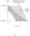
- Figure 7 is a diagram illustrating a velocity tilt diagram.
- the x-axis shows the forward speed of the aircraft and the y-axis shows the tilt (e.g., position or angle of the tilt wing or tilt rotors) which ranges from a (e.g., minimal) cruise position (700) to a (e.g., maximal) hover position (702).
- the tilt e.g., position or angle of the tilt wing or tilt rotors
- the first operating envelope (704), shown with a solid border and filled with a grid pattern, is associated with a tilt wing aircraft. See, for example, multicopter 400 in Figure 4 and tilt wing 302 and fixed rotor 300 in Figure 3A .
- the second operating envelope (706), shown with a dashed border and gray fill, is associated with a (e.g., comparable) aircraft with a forward swept and fixed wing with trailing edge mounted tilt rotors. See, for example, the examples described above.
- the tilt rotor operating envelope (706) is a superset of the tilt wing operating envelope (704) which indicates that the former aircraft configuration is safer and/or more airworthy than the latter and is also able to fly both faster and slower at comparable tilt positions.
- the tilt rotors With a fixed wing, the wing is already (and/or always) pointed in the direction of (forward) travel.
- the tilt rotors When the tilt rotors are at or near the (e.g., maximal) hover position (702), the vehicle can fly around pretty much all the way up to the stall speed (e.g., V 2 ) without having to tilt the motors up to cruise position.
- the tilt rotor operating envelope (706) can stay at the (e.g., maximal) hover position (702) all the way up to V 2 . This greatly increases the operating regime of the tilt rotor operating envelope (706) compared to the tilt wing operating envelope (704). Note for example, all of the gray area above the tilt wing operating envelope (704).
- Another effect which can contribute to the expanded operating envelope for the tilt rotor configuration at or near hover position includes flow turning (see, e.g., Figure 4 ).
- the flow turning over the main wing induces some extra lift.
- this flow turning and its resulting lift are amplified or optimized by tilting the main wing rotors at a slight backward angle from directly down when in a normal hover (e.g., at minimal tilt position 700).
- a tilt wing presents a large frontal area when the tilt wing is tilted up in (e.g., maximal) hover position (702).
- tilt wings are unable to fly forward at any kind of decent speed until at or near the full (e.g., minimal) cruise position (700) or nearly so.
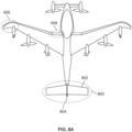
- Figure 8A is a top view of an aircraft with a three-airfoil tail.
- the exemplary multicopter includes a tail (800) with three airfoils: two horizontal stabilizers (802) and a single vertical stabilizer (804).
- the tips (806) of the main wing in this example are curved. For example, this may help to better capture forced airflow from the tip of the propellers, as well as adding to the wing aspect ratio. This results in lower induced drag and higher available lift for a given power input.
- An additional benefit is protecting tip propeller blades from lateral strikes while conducting hover operations close to structures.
- the main wing also includes a shoulder (808) which widens the part of the main wing which connects to the fuselage and helps structurally.
- Figure 8B is a front view of an aircraft with a three-airfoil tail.
- Figure 8B continues the example of Figure 8A .
- the canard rotors (820) are positioned so that they are below the (plane of the) main wing (822). This positioning of the canard rotors improves the thrust line in cruise and reduces interaction between the canard rotors (820) and the main wing (822).
- Figure 8C is a side view of an aircraft with a three-airfoil tail. As this view shows, the canard rotors (840) are positioned so that they are below the (plane of the) main wing (842).
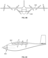
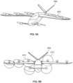
- FIG. 9A is an angled view of an aircraft with a V tail.
- the multicopter has a V tail (900).
- V tail 900
- One benefit to a V tail (900) is that it helps to avoid interactions between the main wing rotors (902) and the surfaces of the tail (900).
- the following figure shows a front view which more clearly illustrates this.
- Figure 9B is a front view of an aircraft with a V tail.
- Figure 9B continues the example of Figure 9A .
- the V tail (910) rises above the main wing rotors as it extends outward from the fuselage to the tip of the wing.
- the V tail (910) is not directly behind and/or directly in the wake of the main wing rotors (912). This minimizes the interactions between the main wing rotors (912) and the V tail's surfaces (910).
- This view also shows that (in this example at least) the main wing rotors in hover (914) are angled or otherwise tilted slightly backward and slightly outward. As described above, this may be desirable because desirable because it allows at least some aircraft to fly in a"magic carpet mode" where the rotors are still in a hover tilt position, but can transition to primarily wing borne flight. The following figure shows an example of this.
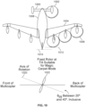
- FIG 10 is a diagram illustrating an embodiment of a multicopter with a truncated fuselage in accordance with the invention, which is capable of flying in a magic carpet mode.
- magic carpet mode refers to a mode in which the rotors are still in a hovering orientation, but the vehicle has been accelerated to an airspeed where a substantial amount of lift is generated by the wing.
- the vehicle speed can be controlled with forward pitch, and altitude can be controlled either by increasing speed to gain efficiency and thus climb rate, or by directly adding thrust to the rotors.
- the multicopter has a canard (1000) with two canard rotors (1002).
- the main wing (1004) which is a fixed wing with a forward sweep, has six main wing rotors (1006) which are attached to the trailing edge of the main wing.
- the fuselage (1008) is relatively short and is referred to herein as a truncated fuselage.
- the end of the fuselage (1010) extends only a little bit past the end of the backmost rotor (1012).
- the rotors are fixed and do not tilt or otherwise change position.
- the truncated fuselage is much shorter and there is no tail per se, both of which keep the weight down.
- the use of fixed rotors e.g., as opposed to tilt rotors also keeps the weight down.
- the truncated fuselage and lack of a tail also produces a smaller footprint which helps with transport (e.g., in a trailer) and the amount of space required for takeoff and/or landing.
- the rotors are at a fixed position tilted back, more on the hover end of the tilt spectrum as opposed to the cruise end of the tilt spectrum (e.g., an axis of rotation that is tilted downward from horizontal at an angle between 20° to 40°, inclusive).
- the axis of rotation (1020) associated with fixed rotor (1022) where the tilt angle is between 20° to 40° is suitable and/or acceptable for magic carpet mode.
- This rotor position (although fixed) permits the multicopter to fly vertically (e.g., not due to aerodynamic lift on the wing, but from the airflow produced by the rotors) as well as forwards (e.g., off the wing).
- This ability or mode of keeping the rotors in a hover-style tilt while flying (e.g., primarily and/or mostly) in a wing borne manner is sometimes referred to as a fly magic carpet mode. It is noted that this ability to fly in a magic carpet mode is not necessarily limited to fixed rotor embodiments. For example, some or all of the above tilt rotor examples not according to the claimed invention may be flown in magic carpet mode (e.g., where the tilt position is the extreme or maximal hover position, or some tilt position between the two extremes).
- Figure 11A is a top view of a multicopter embodiment with a truncated fuselage and tail.
- the embodiment shown here has similarities with the previous multicopter embodiment shown in Figure 10 and for brevity shared features are not discussed herein.
- this embodiment has a tail (1100).
- the fuselage (1102) is a truncated fuselage so the tail (1100) and fuselage (1102) are connected using a boom (1104).
- Figure 11B is a side view of a multicopter embodiment with a truncated fuselage and tail.
- Figure 11B continues the example of Figure 11A . From this view, other features of the multicopter, including a horizontal control surface (1106) and a vertical control surface (1108) on the tail and ski-like landing gear (1110) are more clearly shown.
Landscapes
- Engineering & Computer Science (AREA)
- Aviation & Aerospace Engineering (AREA)
- Mechanical Engineering (AREA)
- Chemical & Material Sciences (AREA)
- Combustion & Propulsion (AREA)
- Toys (AREA)
- Structures Of Non-Positive Displacement Pumps (AREA)
- Braking Arrangements (AREA)
- Rotary Pumps (AREA)
Claims (4)
- Flugzeug, das Folgendes umfasst:einen Rumpf (1008; 1102), wobei der Rumpf ein trunkierter Rumpf ist;einen Hauptflügel (1004), wobei der Hauptflügel ein feststehender, nach vorne gepfeilter und verjüngter Flügel ist;einen Entenflügel (1000); mehrere backbordseitige Rotoren (1006), wobei die mehreren backbordseitigen Rotoren mit einer Hinterkante des Hauptflügels auf der Backbordseite des Flugzeugs gekoppelt sind;mehrere steuerbordseitige Rotoren (1006), wobei die mehreren steuerbordseitigen Rotoren mit der Hinterkante des Hauptflügels auf der Steuerbordseite des Flugzeugs gekoppelt sind; undmindestens einen am Entenflügel angebrachten Entenflügelrotor (1002),wobei die mehreren backbordseitigen Rotoren (1006), die mehreren steuerbordseitigen Rotoren (1006) und der mindestens eine Entenflügelrotor (1002) feststehende Rotoren mit einer Drehachse sind, die von der Horizontalen in einem Winkel zwischen 20° bis 40°, einschließlich, nach unten geneigt ist.
- Flugzeug nach Anspruch 1, wobei das Flugzeug zwei Entenflügelrotoren (1002), drei backbordseitige Kipprotoren (1006) und drei steuerbordseitige Kipprotoren (1006) umfasst.
- Flugzeug nach Anspruch 2, wobei:die zwei Entenflügelrotoren in einer ersten Höhe am Entenflügel angebracht sind; unddie drei backbordseitigen Kipprotoren und die drei steuerbordseitigen Kipprotoren in einer zweiten Höhe, die größer als die erste Höhe ist, an der Hinterkante des Hauptflügels angebracht sind.
- Flugzeug nach Anspruch 3, wobei das Flugzeug ferner ein Dreiblatt-Heckleitwerk (1100) aufweist.
Priority Applications (1)
| Application Number | Priority Date | Filing Date | Title |
|---|---|---|---|
| EP24180326.1A EP4403463A3 (de) | 2018-02-22 | 2018-11-28 | Starrflügelflugzeug mit nachlaufenden rotoren |
Applications Claiming Priority (3)
| Application Number | Priority Date | Filing Date | Title |
|---|---|---|---|
| US15/902,281 US10144503B1 (en) | 2018-02-22 | 2018-02-22 | Fixed wing aircraft with trailing rotors |
| US16/168,461 US11180248B2 (en) | 2018-02-22 | 2018-10-23 | Fixed wing aircraft with trailing rotors |
| PCT/US2018/062855 WO2019164565A1 (en) | 2018-02-22 | 2018-11-28 | Fixed wing aircraft with trailing rotors |
Related Child Applications (2)
| Application Number | Title | Priority Date | Filing Date |
|---|---|---|---|
| EP24180326.1A Division-Into EP4403463A3 (de) | 2018-02-22 | 2018-11-28 | Starrflügelflugzeug mit nachlaufenden rotoren |
| EP24180326.1A Division EP4403463A3 (de) | 2018-02-22 | 2018-11-28 | Starrflügelflugzeug mit nachlaufenden rotoren |
Publications (4)
| Publication Number | Publication Date |
|---|---|
| EP3755622A1 EP3755622A1 (de) | 2020-12-30 |
| EP3755622A4 EP3755622A4 (de) | 2021-11-24 |
| EP3755622B1 true EP3755622B1 (de) | 2024-11-20 |
| EP3755622B8 EP3755622B8 (de) | 2024-11-27 |
Family
ID=64451753
Family Applications (2)
| Application Number | Title | Priority Date | Filing Date |
|---|---|---|---|
| EP18907259.8A Active EP3755622B8 (de) | 2018-02-22 | 2018-11-28 | Starrflügelflugzeug mit nachlaufenden rotoren |
| EP24180326.1A Pending EP4403463A3 (de) | 2018-02-22 | 2018-11-28 | Starrflügelflugzeug mit nachlaufenden rotoren |
Family Applications After (1)
| Application Number | Title | Priority Date | Filing Date |
|---|---|---|---|
| EP24180326.1A Pending EP4403463A3 (de) | 2018-02-22 | 2018-11-28 | Starrflügelflugzeug mit nachlaufenden rotoren |
Country Status (5)
| Country | Link |
|---|---|
| US (2) | US10144503B1 (de) |
| EP (2) | EP3755622B8 (de) |
| CN (2) | CN111655576B (de) |
| NZ (1) | NZ764575A (de) |
| WO (1) | WO2019164565A1 (de) |
Families Citing this family (35)
| Publication number | Priority date | Publication date | Assignee | Title |
|---|---|---|---|---|
| EP3583027A4 (de) * | 2017-03-09 | 2020-03-04 | Shafir, Yehuda | Vertikal startendes und landendes leichtflugzeug |
| US20190241260A1 (en) * | 2018-02-06 | 2019-08-08 | Khaled Abdullah Alhussan | Rotary aircraft and method of use |
| US10144503B1 (en) | 2018-02-22 | 2018-12-04 | Kitty Hawk Corporation | Fixed wing aircraft with trailing rotors |
| US20190337614A1 (en) * | 2018-05-03 | 2019-11-07 | Uber Technologies, Inc. | Vertical takeoff and landing aircraft |
| WO2019217920A1 (en) * | 2018-05-10 | 2019-11-14 | Joby Aero, Inc. | Electric tiltrotor aircraft |
| US12006048B2 (en) | 2018-05-31 | 2024-06-11 | Joby Aero, Inc. | Electric power system architecture and fault tolerant VTOL aircraft using same |
| WO2019232472A1 (en) | 2018-05-31 | 2019-12-05 | Joby Aero Inc. | Electric power system architecture and fault tolerant vtol aircraft using same |
| US10843807B2 (en) | 2018-06-01 | 2020-11-24 | Joby Aero, Inc. | System and method for aircraft noise mitigation |
| WO2020009871A1 (en) | 2018-07-02 | 2020-01-09 | Joby Aero, Inc. | System and method for airspeed determination |
| EP3853736B1 (de) | 2018-09-17 | 2025-10-22 | Joby Aero, Inc. | Flugzeugsteuerungssystem |
| DE102018219179B3 (de) * | 2018-11-09 | 2019-12-05 | Siemens Aktiengesellschaft | Böenlastminderung bei einem Flugzeug |
| WO2020118310A1 (en) | 2018-12-07 | 2020-06-11 | Joby Aero, Inc. | Rotary airfoil and design method therefor |
| AU2019433213B2 (en) | 2018-12-07 | 2025-06-05 | Joby Aero, Inc. | Aircraft control system and method |
| US10845823B2 (en) | 2018-12-19 | 2020-11-24 | Joby Aero, Inc. | Vehicle navigation system |
| EP3959770B1 (de) | 2019-04-23 | 2025-04-23 | Joby Aero, Inc. | Wärmeverwaltungssystem und -verfahren für batterie |
| US11230384B2 (en) | 2019-04-23 | 2022-01-25 | Joby Aero, Inc. | Vehicle cabin thermal management system and method |
| US10988248B2 (en) | 2019-04-25 | 2021-04-27 | Joby Aero, Inc. | VTOL aircraft |
| US10981648B2 (en) | 2019-08-02 | 2021-04-20 | Kitty Hawk Corporation | Fixed wing aircraft with trailing rotors and T-tail |
| USD921565S1 (en) * | 2019-10-02 | 2021-06-08 | Kitty Hawk Corporation | Fixed wing aircraft with tilt rotors |
| CN114340998B (zh) * | 2019-10-09 | 2024-12-27 | 小鹰公司 | 用于不同飞行模式的混合功率系统 |
| US20210403154A1 (en) | 2020-01-31 | 2021-12-30 | Wisk Aero Llc | Aircraft with tilting fan assemblies |
| EP4103470A4 (de) | 2020-02-10 | 2023-12-27 | Wisk Aero LLC | Luftkasten mit schubpropeller |
| US11554865B2 (en) * | 2020-02-18 | 2023-01-17 | Aurora Flight Sciences Corporation | Vertical take-off and landing (VTOL) aircraft and related methods |
| USD1009696S1 (en) | 2020-02-18 | 2024-01-02 | Aurora Flight Sciences Corporation, a subsidiary of The Boeing Company | Aircraft |
| US11472546B2 (en) | 2020-02-24 | 2022-10-18 | Aurora Flight Sciences Corporation | Fixed-wing short-takeoff-and-landing aircraft and related methods |
| EP4162473A4 (de) | 2020-06-05 | 2024-07-03 | Joby Aero, Inc. | Flugzeugsteuerungssystem und -verfahren |
| US11247773B2 (en) | 2020-06-12 | 2022-02-15 | Kitty Hawk Corporation | Pylon mounted tilt rotor |
| CN112407237A (zh) * | 2020-09-30 | 2021-02-26 | 北京北航天宇长鹰无人机科技有限公司 | 一种高升阻比中型无人机 |
| CN112644684B (zh) * | 2020-12-23 | 2022-06-03 | 河北利翔航空科技有限公司 | 一种鸭翼前掠翼无人运输机 |
| US11772773B2 (en) | 2021-01-04 | 2023-10-03 | Aurora Flight Sciences Corporation, a subsidiary of The Boeing Company | Aircraft and related methods |
| US11919631B2 (en) * | 2021-02-08 | 2024-03-05 | Archer Aviation, Inc. | Vertical take-off and landing aircraft with aft rotor tilting |
| KR20230142777A (ko) * | 2021-02-09 | 2023-10-11 | 조비 에어로, 인크. | 항공기 추진 유닛 |
| US12420922B2 (en) | 2021-07-31 | 2025-09-23 | Supernal, Llc | Vertical take-off and landing craft systems and methods |
| US12084184B2 (en) * | 2021-11-10 | 2024-09-10 | Se Aeronautics Inc | Aerospace vehicles having multiple lifting surfaces |
| US11655024B1 (en) | 2022-05-25 | 2023-05-23 | Kitty Hawk Corporation | Battery systems with power optimized energy source and energy storage optimized source |
Family Cites Families (47)
| Publication number | Priority date | Publication date | Assignee | Title |
|---|---|---|---|---|
| US2478847A (en) * | 1944-10-06 | 1949-08-09 | Gen Motors Corp | Convertible helicopter-airplane |
| US2937823A (en) * | 1954-06-03 | 1960-05-24 | Fletch Aire Company Inc | Vertical rising convertiplane having tilting wing channel boundary layer control system |
| US3081964A (en) * | 1958-12-08 | 1963-03-19 | Boeing Co | Airplanes for vertical and/or short take-off and landing |
| US3089666A (en) * | 1961-04-13 | 1963-05-14 | Boeing Co | Airplane having changeable thrust direction |
| US3159361A (en) * | 1962-02-14 | 1964-12-01 | Carl W Weiland | Aircraft |
| US3179354A (en) * | 1962-04-24 | 1965-04-20 | Alvarez-Calderon Alberto | Convertiplane and apparatus thereof |
| US3273827A (en) * | 1964-04-27 | 1966-09-20 | Ryan Aeronautical Co | Propeller-rotor high lift system for aircraft |
| US3856238A (en) * | 1972-04-14 | 1974-12-24 | F Malvestuto | Aircraft transporter |
| IT1152763B (it) * | 1982-01-25 | 1987-01-14 | Ind Aeronautiche E Meccaniche | Aeromobile perfezionato |
| US4629147A (en) | 1984-10-16 | 1986-12-16 | The United States Of America As Represented By The Administrator Of The National Aeronautics And Space Administration | Over-the-wing propeller |
| US4828203A (en) | 1986-12-16 | 1989-05-09 | Vulcan Aircraft Corporation | Vertical/short take-off and landing aircraft |
| US4979698A (en) * | 1988-07-07 | 1990-12-25 | Paul Lederman | Rotor system for winged aircraft |
| US5195702A (en) * | 1991-04-09 | 1993-03-23 | Malvestuto Jr Frank S | Rotor flap apparatus and method |
| US5454531A (en) * | 1993-04-19 | 1995-10-03 | Melkuti; Attila | Ducted propeller aircraft (V/STOL) |
| US5405105A (en) | 1993-05-28 | 1995-04-11 | Hudson Valley V/Stol Aircraft, Inc. | Tilt wing VTOL aircraft |
| US6561456B1 (en) * | 2001-12-06 | 2003-05-13 | Michael Thomas Devine | Vertical/short take-off and landing aircraft |
| US9493235B2 (en) | 2002-10-01 | 2016-11-15 | Dylan T X Zhou | Amphibious vertical takeoff and landing unmanned device |
| FR2864030B1 (fr) * | 2003-12-23 | 2006-02-17 | Eurocopter France | Aeronef convertible pourvu de deux "tilt fan" de part et d'autre du fuselage et d'un troisieme "tilt fan" agence sur la queue de l'aeronef |
| IL199009A (en) | 2009-05-27 | 2013-11-28 | Israel Aerospace Ind Ltd | aircraft |
| US8616492B2 (en) * | 2009-10-09 | 2013-12-31 | Oliver Vtol, Llc | Three wing, six tilt-propulsion units, VTOL aircraft |
| WO2011139316A2 (en) * | 2009-12-29 | 2011-11-10 | Rolls-Royce North American Technologies, Inc. | Aircraft vertical lift device |
| CN102826215B (zh) * | 2012-09-11 | 2015-05-20 | 北京航空航天大学 | 一种可短距起降的轻小型飞翼载人机 |
| US9085355B2 (en) * | 2012-12-07 | 2015-07-21 | Delorean Aerospace, Llc | Vertical takeoff and landing aircraft |
| US9669939B2 (en) | 2013-01-16 | 2017-06-06 | Otto Aviation Group | Aircraft supplemental thrust device and method of operating the same |
| US9475579B2 (en) * | 2013-08-13 | 2016-10-25 | The United States Of America As Represented By The Administrator Of The National Aeronautics And Space Administration | Vertical take-off and landing vehicle with increased cruise efficiency |
| US9694911B2 (en) * | 2014-03-18 | 2017-07-04 | Joby Aviation, Inc. | Aerodynamically efficient lightweight vertical take-off and landing aircraft with pivoting rotors and stowing rotor blades |
| US10144509B2 (en) * | 2014-06-03 | 2018-12-04 | Juan Gabriel Cruz Ayoroa | High performance VTOL aircraft |
| US9845152B2 (en) * | 2014-08-11 | 2017-12-19 | Dusan Milivoi Stan | Apparatus and method for providing control and augmenting thrust at reduced speed and ensuring reduced drag at increased speed |
| US20160101853A1 (en) * | 2014-10-10 | 2016-04-14 | David Wayne Toppenberg | Vertical take off and landing aircraft |
| CN104494812A (zh) * | 2015-01-08 | 2015-04-08 | 常州大学 | 一种具有可倾转轴螺旋桨的固定翼飞行器装置 |
| RU2577931C1 (ru) | 2015-01-13 | 2016-03-20 | Дмитрий Сергеевич Дуров | Гибридный самолет короткого взлета и посадки |
| US10370100B2 (en) * | 2015-03-24 | 2019-08-06 | United States Of America As Represented By The Administrator Of Nasa | Aerodynamically actuated thrust vectoring devices |
| CN204998771U (zh) * | 2015-07-23 | 2016-01-27 | 曹漪 | 一种垂直起降的飞行器 |
| CN105217026B (zh) * | 2015-10-30 | 2017-12-19 | 佛山市神风航空科技有限公司 | 一种复合型飞行器 |
| US20170197700A1 (en) * | 2016-01-11 | 2017-07-13 | Northrop Grumman Systems Corporation | Electric distributed propulsion and high lift system |
| US10926874B2 (en) * | 2016-01-15 | 2021-02-23 | Aurora Flight Sciences Corporation | Hybrid propulsion vertical take-off and landing aircraft |
| US9694906B1 (en) * | 2016-04-18 | 2017-07-04 | King Saud University | Vertical takeoff and landing unmanned aerial vehicle |
| US10696390B2 (en) * | 2016-09-08 | 2020-06-30 | Hop Flyt Inc | Aircraft having independently variable incidence channel wings with independently variable incidence channel canards |
| US10266252B2 (en) | 2016-09-19 | 2019-04-23 | Bell Helicopter Textron Inc. | Wing extension winglets for tiltrotor aircraft |
| US9975631B1 (en) | 2017-11-01 | 2018-05-22 | Kitty Hawk Corporation | Tiltwing multicopter with foldable and non-foldable propellers |
| US10144503B1 (en) | 2018-02-22 | 2018-12-04 | Kitty Hawk Corporation | Fixed wing aircraft with trailing rotors |
| GB201806277D0 (en) * | 2018-04-17 | 2018-05-30 | Flugauto Holding Ltd | Vertical take-off and landing vehicle |
| WO2019217920A1 (en) * | 2018-05-10 | 2019-11-14 | Joby Aero, Inc. | Electric tiltrotor aircraft |
| US10479482B1 (en) * | 2018-12-07 | 2019-11-19 | Kitty Hawk Corporation | Propeller with passive variable pitch and rotatable base |
| EP3702277B1 (de) * | 2019-02-27 | 2021-01-27 | AIRBUS HELICOPTERS DEUTSCHLAND GmbH | Für senkrechtstart und -landung (vtol) geeignetes mehrrotorflugzeug |
| US10981648B2 (en) * | 2019-08-02 | 2021-04-20 | Kitty Hawk Corporation | Fixed wing aircraft with trailing rotors and T-tail |
| CN114340998B (zh) * | 2019-10-09 | 2024-12-27 | 小鹰公司 | 用于不同飞行模式的混合功率系统 |
-
2018
- 2018-02-22 US US15/902,281 patent/US10144503B1/en active Active
- 2018-10-23 US US16/168,461 patent/US11180248B2/en active Active
- 2018-11-28 EP EP18907259.8A patent/EP3755622B8/de active Active
- 2018-11-28 WO PCT/US2018/062855 patent/WO2019164565A1/en not_active Ceased
- 2018-11-28 CN CN201880087396.4A patent/CN111655576B/zh active Active
- 2018-11-28 EP EP24180326.1A patent/EP4403463A3/de active Pending
- 2018-11-28 NZ NZ764575A patent/NZ764575A/en unknown
- 2018-11-28 CN CN202410054177.3A patent/CN118083121A/zh active Pending
Also Published As
| Publication number | Publication date |
|---|---|
| EP3755622A1 (de) | 2020-12-30 |
| US20190256194A1 (en) | 2019-08-22 |
| US10144503B1 (en) | 2018-12-04 |
| EP4403463A2 (de) | 2024-07-24 |
| CN118083121A (zh) | 2024-05-28 |
| US11180248B2 (en) | 2021-11-23 |
| CN111655576A (zh) | 2020-09-11 |
| EP3755622B8 (de) | 2024-11-27 |
| NZ764575A (en) | 2023-03-31 |
| CN111655576B (zh) | 2024-01-23 |
| EP3755622A4 (de) | 2021-11-24 |
| EP4403463A3 (de) | 2024-10-09 |
| WO2019164565A1 (en) | 2019-08-29 |
Similar Documents
| Publication | Publication Date | Title |
|---|---|---|
| EP3755622B1 (de) | Starrflügelflugzeug mit nachlaufenden rotoren | |
| US12515792B2 (en) | Fixed wing aircraft with trailing rotors and T-tail | |
| US12103674B2 (en) | Short takeoff and landing vehicle with forward swept wings | |
| US7118066B2 (en) | Tall V/STOL aircraft | |
| EP3670341A1 (de) | Senkrecht startendes und landendes (vtol) flugzeug | |
| US20230063801A1 (en) | System and method for lift augmentation of aircraft wings | |
| EP4337527B1 (de) | Flugzeug | |
| CN113859526A (zh) | 可垂直起降的固定翼飞机及其控制方法 | |
| RU2141432C1 (ru) | Самолет вертикального взлета и посадки бетенева-рогова | |
| CA2859258A1 (en) | Apparatus and method for providing high lift at zero speed and low drag at higher speed | |
| HK1179227A (en) | Fixed-wing and electric multi-rotor composite aircraft |
Legal Events
| Date | Code | Title | Description |
|---|---|---|---|
| STAA | Information on the status of an ep patent application or granted ep patent |
Free format text: STATUS: THE INTERNATIONAL PUBLICATION HAS BEEN MADE |
|
| PUAI | Public reference made under article 153(3) epc to a published international application that has entered the european phase |
Free format text: ORIGINAL CODE: 0009012 |
|
| STAA | Information on the status of an ep patent application or granted ep patent |
Free format text: STATUS: REQUEST FOR EXAMINATION WAS MADE |
|
| 17P | Request for examination filed |
Effective date: 20200507 |
|
| AK | Designated contracting states |
Kind code of ref document: A1 Designated state(s): AL AT BE BG CH CY CZ DE DK EE ES FI FR GB GR HR HU IE IS IT LI LT LU LV MC MK MT NL NO PL PT RO RS SE SI SK SM TR |
|
| AX | Request for extension of the european patent |
Extension state: BA ME |
|
| DAV | Request for validation of the european patent (deleted) | ||
| DAX | Request for extension of the european patent (deleted) | ||
| A4 | Supplementary search report drawn up and despatched |
Effective date: 20211022 |
|
| RIC1 | Information provided on ipc code assigned before grant |
Ipc: B64C 5/02 20060101ALI20211018BHEP Ipc: B64C 39/12 20060101ALI20211018BHEP Ipc: B64C 11/46 20060101AFI20211018BHEP |
|
| STAA | Information on the status of an ep patent application or granted ep patent |
Free format text: STATUS: EXAMINATION IS IN PROGRESS |
|
| 17Q | First examination report despatched |
Effective date: 20221214 |
|
| P01 | Opt-out of the competence of the unified patent court (upc) registered |
Effective date: 20230605 |
|
| GRAP | Despatch of communication of intention to grant a patent |
Free format text: ORIGINAL CODE: EPIDOSNIGR1 |
|
| STAA | Information on the status of an ep patent application or granted ep patent |
Free format text: STATUS: GRANT OF PATENT IS INTENDED |
|
| INTG | Intention to grant announced |
Effective date: 20240221 |
|
| GRAJ | Information related to disapproval of communication of intention to grant by the applicant or resumption of examination proceedings by the epo deleted |
Free format text: ORIGINAL CODE: EPIDOSDIGR1 |
|
| STAA | Information on the status of an ep patent application or granted ep patent |
Free format text: STATUS: EXAMINATION IS IN PROGRESS |
|
| GRAP | Despatch of communication of intention to grant a patent |
Free format text: ORIGINAL CODE: EPIDOSNIGR1 |
|
| STAA | Information on the status of an ep patent application or granted ep patent |
Free format text: STATUS: GRANT OF PATENT IS INTENDED |
|
| INTC | Intention to grant announced (deleted) | ||
| INTG | Intention to grant announced |
Effective date: 20240619 |
|
| GRAS | Grant fee paid |
Free format text: ORIGINAL CODE: EPIDOSNIGR3 |
|
| GRAA | (expected) grant |
Free format text: ORIGINAL CODE: 0009210 |
|
| STAA | Information on the status of an ep patent application or granted ep patent |
Free format text: STATUS: THE PATENT HAS BEEN GRANTED |
|
| REG | Reference to a national code |
Ref country code: DE Ref legal event code: R081 Ref document number: 602018076857 Country of ref document: DE Owner name: KITTY HAWK CORP., PALO ALTO, US Free format text: FORMER OWNER: KITTY HAWK CORP., MOUNTAIN VIEW, CA, US |
|
| AK | Designated contracting states |
Kind code of ref document: B1 Designated state(s): AL AT BE BG CH CY CZ DE DK EE ES FI FR GB GR HR HU IE IS IT LI LT LU LV MC MK MT NL NO PL PT RO RS SE SI SK SM TR |
|
| REG | Reference to a national code |
Ref country code: GB Ref legal event code: FG4D |
|
| RAP4 | Party data changed (patent owner data changed or rights of a patent transferred) |
Owner name: KITTY HAWK CORPORATION |
|
| REG | Reference to a national code |
Ref country code: CH Ref legal event code: EP |
|
| REG | Reference to a national code |
Ref country code: DE Ref legal event code: R096 Ref document number: 602018076857 Country of ref document: DE |
|
| REG | Reference to a national code |
Ref country code: IE Ref legal event code: FG4D |
|
| REG | Reference to a national code |
Ref country code: LT Ref legal event code: MG9D |
|
| REG | Reference to a national code |
Ref country code: NL Ref legal event code: MP Effective date: 20241120 |
|
| PG25 | Lapsed in a contracting state [announced via postgrant information from national office to epo] |
Ref country code: HR Free format text: LAPSE BECAUSE OF FAILURE TO SUBMIT A TRANSLATION OF THE DESCRIPTION OR TO PAY THE FEE WITHIN THE PRESCRIBED TIME-LIMIT Effective date: 20241120 Ref country code: PT Free format text: LAPSE BECAUSE OF FAILURE TO SUBMIT A TRANSLATION OF THE DESCRIPTION OR TO PAY THE FEE WITHIN THE PRESCRIBED TIME-LIMIT Effective date: 20250320 Ref country code: IS Free format text: LAPSE BECAUSE OF FAILURE TO SUBMIT A TRANSLATION OF THE DESCRIPTION OR TO PAY THE FEE WITHIN THE PRESCRIBED TIME-LIMIT Effective date: 20250320 |
|
| PG25 | Lapsed in a contracting state [announced via postgrant information from national office to epo] |
Ref country code: NL Free format text: LAPSE BECAUSE OF FAILURE TO SUBMIT A TRANSLATION OF THE DESCRIPTION OR TO PAY THE FEE WITHIN THE PRESCRIBED TIME-LIMIT Effective date: 20241120 Ref country code: FI Free format text: LAPSE BECAUSE OF FAILURE TO SUBMIT A TRANSLATION OF THE DESCRIPTION OR TO PAY THE FEE WITHIN THE PRESCRIBED TIME-LIMIT Effective date: 20241120 |
|
| REG | Reference to a national code |
Ref country code: AT Ref legal event code: MK05 Ref document number: 1743369 Country of ref document: AT Kind code of ref document: T Effective date: 20241120 |
|
| PG25 | Lapsed in a contracting state [announced via postgrant information from national office to epo] |
Ref country code: BG Free format text: LAPSE BECAUSE OF FAILURE TO SUBMIT A TRANSLATION OF THE DESCRIPTION OR TO PAY THE FEE WITHIN THE PRESCRIBED TIME-LIMIT Effective date: 20241120 |
|
| PG25 | Lapsed in a contracting state [announced via postgrant information from national office to epo] |
Ref country code: ES Free format text: LAPSE BECAUSE OF FAILURE TO SUBMIT A TRANSLATION OF THE DESCRIPTION OR TO PAY THE FEE WITHIN THE PRESCRIBED TIME-LIMIT Effective date: 20241120 |
|
| PG25 | Lapsed in a contracting state [announced via postgrant information from national office to epo] |
Ref country code: NO Free format text: LAPSE BECAUSE OF FAILURE TO SUBMIT A TRANSLATION OF THE DESCRIPTION OR TO PAY THE FEE WITHIN THE PRESCRIBED TIME-LIMIT Effective date: 20250220 |
|
| PG25 | Lapsed in a contracting state [announced via postgrant information from national office to epo] |
Ref country code: AT Free format text: LAPSE BECAUSE OF FAILURE TO SUBMIT A TRANSLATION OF THE DESCRIPTION OR TO PAY THE FEE WITHIN THE PRESCRIBED TIME-LIMIT Effective date: 20241120 Ref country code: LV Free format text: LAPSE BECAUSE OF FAILURE TO SUBMIT A TRANSLATION OF THE DESCRIPTION OR TO PAY THE FEE WITHIN THE PRESCRIBED TIME-LIMIT Effective date: 20241120 Ref country code: GR Free format text: LAPSE BECAUSE OF FAILURE TO SUBMIT A TRANSLATION OF THE DESCRIPTION OR TO PAY THE FEE WITHIN THE PRESCRIBED TIME-LIMIT Effective date: 20250221 |
|
| PG25 | Lapsed in a contracting state [announced via postgrant information from national office to epo] |
Ref country code: PL Free format text: LAPSE BECAUSE OF FAILURE TO SUBMIT A TRANSLATION OF THE DESCRIPTION OR TO PAY THE FEE WITHIN THE PRESCRIBED TIME-LIMIT Effective date: 20241120 |
|
| PG25 | Lapsed in a contracting state [announced via postgrant information from national office to epo] |
Ref country code: RS Free format text: LAPSE BECAUSE OF FAILURE TO SUBMIT A TRANSLATION OF THE DESCRIPTION OR TO PAY THE FEE WITHIN THE PRESCRIBED TIME-LIMIT Effective date: 20250220 |
|
| REG | Reference to a national code |
Ref country code: CH Ref legal event code: PL |
|
| PG25 | Lapsed in a contracting state [announced via postgrant information from national office to epo] |
Ref country code: SM Free format text: LAPSE BECAUSE OF FAILURE TO SUBMIT A TRANSLATION OF THE DESCRIPTION OR TO PAY THE FEE WITHIN THE PRESCRIBED TIME-LIMIT Effective date: 20241120 |
|
| PG25 | Lapsed in a contracting state [announced via postgrant information from national office to epo] |
Ref country code: DK Free format text: LAPSE BECAUSE OF FAILURE TO SUBMIT A TRANSLATION OF THE DESCRIPTION OR TO PAY THE FEE WITHIN THE PRESCRIBED TIME-LIMIT Effective date: 20241120 |
|
| PG25 | Lapsed in a contracting state [announced via postgrant information from national office to epo] |
Ref country code: LU Free format text: LAPSE BECAUSE OF NON-PAYMENT OF DUE FEES Effective date: 20241128 |
|
| REG | Reference to a national code |
Ref country code: CH Ref legal event code: PL |
|
| PG25 | Lapsed in a contracting state [announced via postgrant information from national office to epo] |
Ref country code: CH Free format text: LAPSE BECAUSE OF NON-PAYMENT OF DUE FEES Effective date: 20241130 |
|
| PG25 | Lapsed in a contracting state [announced via postgrant information from national office to epo] |
Ref country code: RO Free format text: LAPSE BECAUSE OF FAILURE TO SUBMIT A TRANSLATION OF THE DESCRIPTION OR TO PAY THE FEE WITHIN THE PRESCRIBED TIME-LIMIT Effective date: 20241120 |
|
| PG25 | Lapsed in a contracting state [announced via postgrant information from national office to epo] |
Ref country code: SK Free format text: LAPSE BECAUSE OF FAILURE TO SUBMIT A TRANSLATION OF THE DESCRIPTION OR TO PAY THE FEE WITHIN THE PRESCRIBED TIME-LIMIT Effective date: 20241120 |
|
| PG25 | Lapsed in a contracting state [announced via postgrant information from national office to epo] |
Ref country code: CZ Free format text: LAPSE BECAUSE OF FAILURE TO SUBMIT A TRANSLATION OF THE DESCRIPTION OR TO PAY THE FEE WITHIN THE PRESCRIBED TIME-LIMIT Effective date: 20241120 |
|
| PG25 | Lapsed in a contracting state [announced via postgrant information from national office to epo] |
Ref country code: IT Free format text: LAPSE BECAUSE OF FAILURE TO SUBMIT A TRANSLATION OF THE DESCRIPTION OR TO PAY THE FEE WITHIN THE PRESCRIBED TIME-LIMIT Effective date: 20241120 |
|
| REG | Reference to a national code |
Ref country code: DE Ref legal event code: R097 Ref document number: 602018076857 Country of ref document: DE |
|
| REG | Reference to a national code |
Ref country code: BE Ref legal event code: MM Effective date: 20241130 |
|
| PG25 | Lapsed in a contracting state [announced via postgrant information from national office to epo] |
Ref country code: SE Free format text: LAPSE BECAUSE OF FAILURE TO SUBMIT A TRANSLATION OF THE DESCRIPTION OR TO PAY THE FEE WITHIN THE PRESCRIBED TIME-LIMIT Effective date: 20241120 |
|
| PG25 | Lapsed in a contracting state [announced via postgrant information from national office to epo] |
Ref country code: MC Free format text: LAPSE BECAUSE OF FAILURE TO SUBMIT A TRANSLATION OF THE DESCRIPTION OR TO PAY THE FEE WITHIN THE PRESCRIBED TIME-LIMIT Effective date: 20241120 |
|
| PLBE | No opposition filed within time limit |
Free format text: ORIGINAL CODE: 0009261 |
|
| STAA | Information on the status of an ep patent application or granted ep patent |
Free format text: STATUS: NO OPPOSITION FILED WITHIN TIME LIMIT |
|
| PG25 | Lapsed in a contracting state [announced via postgrant information from national office to epo] |
Ref country code: BE Free format text: LAPSE BECAUSE OF NON-PAYMENT OF DUE FEES Effective date: 20241130 |
|
| 26N | No opposition filed |
Effective date: 20250821 |
|
| PG25 | Lapsed in a contracting state [announced via postgrant information from national office to epo] |
Ref country code: IE Free format text: LAPSE BECAUSE OF NON-PAYMENT OF DUE FEES Effective date: 20241128 |
|
| PGFP | Annual fee paid to national office [announced via postgrant information from national office to epo] |
Ref country code: DE Payment date: 20251022 Year of fee payment: 8 |
|
| PGFP | Annual fee paid to national office [announced via postgrant information from national office to epo] |
Ref country code: GB Payment date: 20251023 Year of fee payment: 8 |
|
| PGFP | Annual fee paid to national office [announced via postgrant information from national office to epo] |
Ref country code: FR Payment date: 20251022 Year of fee payment: 8 |