EP4032807B1 - Flugzeug mit einziehbaren wirbelgeneratoren - Google Patents
Flugzeug mit einziehbaren wirbelgeneratoren Download PDFInfo
- Publication number
- EP4032807B1 EP4032807B1 EP21173058.5A EP21173058A EP4032807B1 EP 4032807 B1 EP4032807 B1 EP 4032807B1 EP 21173058 A EP21173058 A EP 21173058A EP 4032807 B1 EP4032807 B1 EP 4032807B1
- Authority
- EP
- European Patent Office
- Prior art keywords
- aircraft
- vortex generators
- vortex
- wing
- propeller
- Prior art date
- Legal status (The legal status is an assumption and is not a legal conclusion. Google has not performed a legal analysis and makes no representation as to the accuracy of the status listed.)
- Active
Links
Images


Classifications
-
- B—PERFORMING OPERATIONS; TRANSPORTING
- B60—VEHICLES IN GENERAL
- B60L—PROPULSION OF ELECTRICALLY-PROPELLED VEHICLES; SUPPLYING ELECTRIC POWER FOR AUXILIARY EQUIPMENT OF ELECTRICALLY-PROPELLED VEHICLES; ELECTRODYNAMIC BRAKE SYSTEMS FOR VEHICLES IN GENERAL; MAGNETIC SUSPENSION OR LEVITATION FOR VEHICLES; MONITORING OPERATING VARIABLES OF ELECTRICALLY-PROPELLED VEHICLES; ELECTRIC SAFETY DEVICES FOR ELECTRICALLY-PROPELLED VEHICLES
- B60L50/00—Electric propulsion with power supplied within the vehicle
- B60L50/50—Electric propulsion with power supplied within the vehicle using propulsion power supplied by batteries or fuel cells
- B60L50/70—Electric propulsion with power supplied within the vehicle using propulsion power supplied by batteries or fuel cells using power supplied by fuel cells
- B60L50/71—Arrangement of fuel cells within vehicles specially adapted for electric vehicles
-
- B—PERFORMING OPERATIONS; TRANSPORTING
- B60—VEHICLES IN GENERAL
- B60L—PROPULSION OF ELECTRICALLY-PROPELLED VEHICLES; SUPPLYING ELECTRIC POWER FOR AUXILIARY EQUIPMENT OF ELECTRICALLY-PROPELLED VEHICLES; ELECTRODYNAMIC BRAKE SYSTEMS FOR VEHICLES IN GENERAL; MAGNETIC SUSPENSION OR LEVITATION FOR VEHICLES; MONITORING OPERATING VARIABLES OF ELECTRICALLY-PROPELLED VEHICLES; ELECTRIC SAFETY DEVICES FOR ELECTRICALLY-PROPELLED VEHICLES
- B60L58/00—Methods or circuit arrangements for monitoring or controlling batteries or fuel cells, specially adapted for electric vehicles
- B60L58/40—Methods or circuit arrangements for monitoring or controlling batteries or fuel cells, specially adapted for electric vehicles for controlling a combination of batteries and fuel cells
-
- B—PERFORMING OPERATIONS; TRANSPORTING
- B64—AIRCRAFT; AVIATION; COSMONAUTICS
- B64C—AEROPLANES; HELICOPTERS
- B64C23/00—Influencing air flow over aircraft surfaces, not otherwise provided for
- B64C23/06—Influencing air flow over aircraft surfaces, not otherwise provided for by generating vortices
-
- B—PERFORMING OPERATIONS; TRANSPORTING
- B64—AIRCRAFT; AVIATION; COSMONAUTICS
- B64D—EQUIPMENT FOR FITTING IN OR TO AIRCRAFT; FLIGHT SUITS; PARACHUTES; ARRANGEMENT OR MOUNTING OF POWER PLANTS OR PROPULSION TRANSMISSIONS IN AIRCRAFT
- B64D27/00—Arrangement or mounting of power plants in aircraft; Aircraft characterised by the type or position of power plants
- B64D27/02—Aircraft characterised by the type or position of power plants
- B64D27/30—Aircraft characterised by electric power plants
- B64D27/31—Aircraft characterised by electric power plants within, or attached to, wings
-
- B—PERFORMING OPERATIONS; TRANSPORTING
- B64—AIRCRAFT; AVIATION; COSMONAUTICS
- B64D—EQUIPMENT FOR FITTING IN OR TO AIRCRAFT; FLIGHT SUITS; PARACHUTES; ARRANGEMENT OR MOUNTING OF POWER PLANTS OR PROPULSION TRANSMISSIONS IN AIRCRAFT
- B64D27/00—Arrangement or mounting of power plants in aircraft; Aircraft characterised by the type or position of power plants
- B64D27/02—Aircraft characterised by the type or position of power plants
- B64D27/30—Aircraft characterised by electric power plants
- B64D27/34—All-electric aircraft
-
- B—PERFORMING OPERATIONS; TRANSPORTING
- B64—AIRCRAFT; AVIATION; COSMONAUTICS
- B64D—EQUIPMENT FOR FITTING IN OR TO AIRCRAFT; FLIGHT SUITS; PARACHUTES; ARRANGEMENT OR MOUNTING OF POWER PLANTS OR PROPULSION TRANSMISSIONS IN AIRCRAFT
- B64D27/00—Arrangement or mounting of power plants in aircraft; Aircraft characterised by the type or position of power plants
- B64D27/02—Aircraft characterised by the type or position of power plants
- B64D27/30—Aircraft characterised by electric power plants
- B64D27/35—Arrangements for on-board electric energy production, distribution, recovery or storage
- B64D27/355—Arrangements for on-board electric energy production, distribution, recovery or storage using fuel cells
-
- B—PERFORMING OPERATIONS; TRANSPORTING
- B64—AIRCRAFT; AVIATION; COSMONAUTICS
- B64D—EQUIPMENT FOR FITTING IN OR TO AIRCRAFT; FLIGHT SUITS; PARACHUTES; ARRANGEMENT OR MOUNTING OF POWER PLANTS OR PROPULSION TRANSMISSIONS IN AIRCRAFT
- B64D31/00—Power plant control systems; Arrangement of power plant control systems in aircraft
- B64D31/16—Power plant control systems; Arrangement of power plant control systems in aircraft for electric power plants
-
- B—PERFORMING OPERATIONS; TRANSPORTING
- B64—AIRCRAFT; AVIATION; COSMONAUTICS
- B64D—EQUIPMENT FOR FITTING IN OR TO AIRCRAFT; FLIGHT SUITS; PARACHUTES; ARRANGEMENT OR MOUNTING OF POWER PLANTS OR PROPULSION TRANSMISSIONS IN AIRCRAFT
- B64D37/00—Arrangements in connection with fuel supply for power plant
- B64D37/30—Fuel systems for specific fuels
-
- B—PERFORMING OPERATIONS; TRANSPORTING
- B64—AIRCRAFT; AVIATION; COSMONAUTICS
- B64U—UNMANNED AERIAL VEHICLES [UAV]; EQUIPMENT THEREFOR
- B64U50/00—Propulsion; Power supply
- B64U50/10—Propulsion
- B64U50/19—Propulsion using electrically powered motors
-
- H—ELECTRICITY
- H01—ELECTRIC ELEMENTS
- H01M—PROCESSES OR MEANS, e.g. BATTERIES, FOR THE DIRECT CONVERSION OF CHEMICAL ENERGY INTO ELECTRICAL ENERGY
- H01M8/00—Fuel cells; Manufacture thereof
- H01M8/04—Auxiliary arrangements, e.g. for control of pressure or for circulation of fluids
- H01M8/04082—Arrangements for control of reactant parameters, e.g. pressure or concentration
- H01M8/04089—Arrangements for control of reactant parameters, e.g. pressure or concentration of gaseous reactants
-
- H—ELECTRICITY
- H01—ELECTRIC ELEMENTS
- H01M—PROCESSES OR MEANS, e.g. BATTERIES, FOR THE DIRECT CONVERSION OF CHEMICAL ENERGY INTO ELECTRICAL ENERGY
- H01M8/00—Fuel cells; Manufacture thereof
- H01M8/04—Auxiliary arrangements, e.g. for control of pressure or for circulation of fluids
- H01M8/04082—Arrangements for control of reactant parameters, e.g. pressure or concentration
- H01M8/04201—Reactant storage and supply, e.g. means for feeding, pipes
-
- B—PERFORMING OPERATIONS; TRANSPORTING
- B60—VEHICLES IN GENERAL
- B60L—PROPULSION OF ELECTRICALLY-PROPELLED VEHICLES; SUPPLYING ELECTRIC POWER FOR AUXILIARY EQUIPMENT OF ELECTRICALLY-PROPELLED VEHICLES; ELECTRODYNAMIC BRAKE SYSTEMS FOR VEHICLES IN GENERAL; MAGNETIC SUSPENSION OR LEVITATION FOR VEHICLES; MONITORING OPERATING VARIABLES OF ELECTRICALLY-PROPELLED VEHICLES; ELECTRIC SAFETY DEVICES FOR ELECTRICALLY-PROPELLED VEHICLES
- B60L2200/00—Type of vehicles
- B60L2200/10—Air crafts
-
- H—ELECTRICITY
- H01—ELECTRIC ELEMENTS
- H01M—PROCESSES OR MEANS, e.g. BATTERIES, FOR THE DIRECT CONVERSION OF CHEMICAL ENERGY INTO ELECTRICAL ENERGY
- H01M2220/00—Batteries for particular applications
- H01M2220/20—Batteries in motive systems, e.g. vehicle, ship, plane
-
- H—ELECTRICITY
- H01—ELECTRIC ELEMENTS
- H01M—PROCESSES OR MEANS, e.g. BATTERIES, FOR THE DIRECT CONVERSION OF CHEMICAL ENERGY INTO ELECTRICAL ENERGY
- H01M2250/00—Fuel cells for particular applications; Specific features of fuel cell system
- H01M2250/20—Fuel cells in motive systems, e.g. vehicle, ship, plane
-
- Y—GENERAL TAGGING OF NEW TECHNOLOGICAL DEVELOPMENTS; GENERAL TAGGING OF CROSS-SECTIONAL TECHNOLOGIES SPANNING OVER SEVERAL SECTIONS OF THE IPC; TECHNICAL SUBJECTS COVERED BY FORMER USPC CROSS-REFERENCE ART COLLECTIONS [XRACs] AND DIGESTS
- Y02—TECHNOLOGIES OR APPLICATIONS FOR MITIGATION OR ADAPTATION AGAINST CLIMATE CHANGE
- Y02T—CLIMATE CHANGE MITIGATION TECHNOLOGIES RELATED TO TRANSPORTATION
- Y02T50/00—Aeronautics or air transport
- Y02T50/10—Drag reduction
-
- Y—GENERAL TAGGING OF NEW TECHNOLOGICAL DEVELOPMENTS; GENERAL TAGGING OF CROSS-SECTIONAL TECHNOLOGIES SPANNING OVER SEVERAL SECTIONS OF THE IPC; TECHNICAL SUBJECTS COVERED BY FORMER USPC CROSS-REFERENCE ART COLLECTIONS [XRACs] AND DIGESTS
- Y02—TECHNOLOGIES OR APPLICATIONS FOR MITIGATION OR ADAPTATION AGAINST CLIMATE CHANGE
- Y02T—CLIMATE CHANGE MITIGATION TECHNOLOGIES RELATED TO TRANSPORTATION
- Y02T90/00—Enabling technologies or technologies with a potential or indirect contribution to GHG emissions mitigation
- Y02T90/40—Application of hydrogen technology to transportation, e.g. using fuel cells
Definitions
- the invention relates to a fixed-wing aircraft that comprises at least one vortex generator movable through an outer surface of the aircraft between a retracted state and a fully extended state and an electronic control unit adapted to control actuation of the at least one vortex generator.
- the invention also relates to a method for operating a fixed-wing aircraft comprising at least one vortex generator movable between a retracted state and a fully extended state.
- the invention is particularly useful for fixed-wing propeller aircraft, in particular aircraft comprising at least three propeller propulsion units per wing, in particular having electric propulsion units.
- EP 1 896 323 B1 and US 2007/018056 A1 disclose a flow control device comprising: a flow control surface over which fluid is designed to flow in a predetermined direction; vortex generators associated with the flow control surface, each respective vortex generator having a pivot axis that forms an acute angle with respect to the predetermined direction and capable of being positioned in both of an extended state, in which the respective vortex generators function to create a swirling fluid flow, and a retracted state, in which the respective vortex generators are pivoted via the pivot axis so as to lie on top of and in a parallel direction to the overlying flow control surface, and an actuator associated with each of the respective vortex generators, each actuator adapted to state the associated vortex generator between the extended and retracted states.
- US 3,263,945 discloses an aircraft wing comprising a main section and a drooping nose section having a pivotal mounting on the main section, said main section and nose section having respective upper surfaces which possess a substantially continuous common chord line when said sections are in a first positional relationship, said nose section pivoting on said pivotal mounting relative to said main section to a second positional relationship in which said upper surfaces are separated by a gap, at least one sealing plate pivotally mounted on said main section and lying in a retracted state wholly inward of said upper surfaces when said main and nose sections are in said first positional relationship, means moving said sealing plate into said gap to close it when said main and nose sections are brought into said second positional relationship, and a series of blades upstanding on said sealing plate and constituting vortex generators, said blades lying retracted wholly inward of said upper surfaces of said main and nose sections when said sections are in said first positional relationship, and projecting out above said upper surfaces when said sections are in said second positional relationship and the sealing plate is in the gap.
- US 4,039,161 discloses vortex generators connected to a control surface in front of the hinge line of the control surface so that when the control surface is deflected, the vortex generators project into the airstream on the opposite side from the deflecting control surface.
- the action of the vortex generators causes the airflow to remain attached to the control surface at higher angles of attack than would otherwise be possible thus increasing the lift of the air foil and control surface.
- US 5,253,828 discloses a concealable flap actuated vortex generator for generating a vortex on a lifting surface assembly, and an improved aircraft flight-lifting surface having such concealable flap actuated vortex generators.
- the flap of the lifting surface assembly is in the nominal (non-extended or non-deflected) state, the vortex generator is unexposed.
- the flap is actuated by a flap actuator, the flap is extended or deflected from the nominal state, thereby projecting or exposing the vortex generator into an operational state and enabling the generation of a vortex.
- US 8,657,238 B2 discloses a device and methods for low-speed performance improvement of a lifting surface assembly are disclosed. At least one vortex generator is coupled to the lifting surface assembly, and the vortex generator is extended through the lifting surface assembly by drooping a hinged leading coupled to the lifting surface assembly to increase lift. The vortex generator is retracted inside the lifting surface assembly to decrease drag.
- US 10, 202,187 B2 discloses a vortex generator arrangement for an aircraft including a surface section, a flap element pivotable between a first state and a second state, a biasing arrangement biasing the flap element towards the second state, retaining devices retaining the flap element in the first or second state, and a release device releasing the flap element from the first retaining device.
- the biasing arrangement, the first retaining device and the second retaining device are configured such that the second retaining device automatically retains the flap element in the second state after the flap element has been pivoted by the biasing arrangement from the first state into the second state.
- the second retaining device automatically releases the flap element, which pivots against the force of the biasing arrangement into the first state and is automatically retained therein by the first retaining device.
- a retractable chine assembly includes at least one chine which is hingebly mountable to a surface such as of an aircraft having a wing.
- the chine is preferably configured to be movable between stowed and deployed positions.
- the aircraft may include an engine nacelle which may be mounted on an underside of the wing.
- the nacelle may generate a nacelle wake that passes over the wing upper surface at high angles of attack and induces flow separation.
- the chine is preferably configured such that a vortex generated thereby interacts which the nacelle wake to delay flow separation and stall.
- US 6 837 465 B2 discloses a flow control device and more particularly to reactive modular flow control device with deployable flow effectors. Further disclosed is a method of operating the flow control device.
- One embodiment includes a method of controlling air flow across a surface of an aircraft under certain flight conditions comprising the steps of sensing fluid separation from the surface by measuring the pressure on the surface; determining a standard deviation of the pressure measurements over a period of time; and deploying a flow of effector in response to the standard deviation of the pressure measurements exceeding a predetermined threshold number.
- DE 10 2015 120 958 A1 discloses an actuator module for the controllable generation of turbulence by positioning turbulence surfaces along a surface element has an elongate module base plate and a plurality of flat-shaped bending actuators.
- Each of the bending actuators comprises a fibre composite panel with shape memory conductors integrated into the fibre composite.
- the fibre composite panel is attached to the module base plate on one attachment side, and the shape memory conductors are designed in such a way that the fibre composite panel extends in the inactive state of the shape memory conductors along the surface of the module base plate and in the active state, starting from the attachment side the surface of the module base plate curves away.
- the actuator module comprises an arrangement of supply lines extending along the module base plate for electrically activating the bending actuators.
- US 3 960 345 A discloses a strake, or strakes, or faired simulation of same, mounted on a typical engine nacelle or similar wing mounted body to reduce or prevent the formation of vortices usually occurring with nacelle-wing combinations to improve the lift and drag characteristics of the combination and improve the stability of the aircraft since the undesirable variations of downwash changes over the tail surfaces are reduced or eliminated.
- US 10 137 979 B1 discloses A forebody flow control system and more particularly an aircraft or missile flow control system for enhanced manoeuvrability and stabilization at high angles of attack. US 10 137 979 B1 further relates to a method of operating the flow control system.
- US 7 878 457 B2 discloses a flow control device including a flow control surface over which fluid is designed to flow in a predetermined direction.
- Vortex generators are associated with the flow control surface.
- Each respective vortex generator has a pivot axis that forms an acute angle with respect to the predetermined direction and is capable of being positioned in both of an extended state, in which the respective vortex generators function to create a swirling fluid flow, and a retracted state, in which the respective vortex generators are pivoted via the pivot axis so as to lie adjacent to the flow control surface.
- An actuator is associated with each of the vortex generators, each actuator adapted to position the associated vortex generator between the extended and retracted states.
- the flow control device is disclosed to be used in tiltrotor vehicles.
- the object is achieved by fixed-wing aircraft, at least comprising at least one vortex generator movable through an outer surface of the aircraft between a retracted state and a fully extended state by at least one electric motor, this at least one electric motor being exclusively adapted to actuate this at least one vortex generator, and comprising an electronic control unit adapted to control operation of the electric motor for direct actuation of the at least one vortex generator.
- the aircraft further comprises multiple vortex generators on each wing.
- multiple propeller propulsion units are attached at each wing
- sets / subgroups of at least one vortex generator each are positioned on the wings behind at least two propellers, i.e., at least one set or subgroup comprising at least one vortex generator positioned behind a first propeller and another set or subgroup comprising at least one vortex generator positioned behind a second propeller of the same wing.
- the at least one vortex generator of one set is actuatable or movable differently from the at least one vortex generator of another set, which may also be expressed in that the vortex generators of these sets are actuatable "selectively between sets".
- This aircraft has the advantage that the airflow over a fixed-wing aircraft's outer surface, in particular lifting surface, can be influenced in a particularly flexible manner, thus allowing for a greater degree of flow control.
- the vortex generators When the vortex generators are actuated individually (i.e., independently from other vortex generators) and/or in groups, they can be actuated / moved to a desired deployment state (e.g., retracted, partially extended, or fully extended state, as detailed further below) specifically suited to their local position during the aircraft's current aerodynamic condition while other vortex generators at other positions can be deployed differently.
- the at least one vortex generator may be actuated to at least one intermediate state between the fully extended state and the retracted state, i.e., to at least one partially extended state.
- the partially extended states may be steps of the fully extended state, e.g., 20 %, 40 %, 60 %, 80%.
- the partially extended states may be controlled continuously or quasi-continuously, e.g., in steps of 1% of the fully extended state. This ability may also be expressed such that the vortex generator is differentially extendable.
- the electronic control unit is adapted to control operation of an electric motor and thus the actuation of at least one vortex generator driven or actuated by this electric motor. That an electric motor is exclusively used or adapted to actuate at least one vortex generator comprises that the motor is not adapted to actuate a flow control surface of another type (i.e. not a vortex generator) such as a leading or trailing edge control surface like a flap, an aileron etc. Thus, the vortex generators may be actuated independently from an actuation or movement of a flow control surface of another type, if so desired.
- At least one vortex generator of the aircraft is exclusively actuated by operation of an electric motor while at least one other vortex generator of the aircraft is actuated together with a flow control surface. It is thus possible that a subgroup of vortex generators is movable independently from an actuation of a flow control surface of another type while another subgroup of vortex generators is only movable together with an actuation or movement of a flow control surface, e.g. because the movements are mechanically coupled / linked to each other, e.g., because a subgroup of vortex generators and at least one control surface are actuated by the same electric motor or mechanically by the pilot.
- At least one vortex generator may, e.g., be positioned on either side of a lifting surface (e.g., wings / tails), primary and secondary control surfaces (e.g., ailerons / rudders / elevators / flaps), fuselage and / or propulsion system (e.g., pod / engine fairing).
- a lifting surface e.g., wings / tails
- primary and secondary control surfaces e.g., ailerons / rudders / elevators / flaps
- fuselage and / or propulsion system e.g., pod / engine fairing
- the aircraft comprises multiple vortex generators and at least one vortex generator out of these multiple vortex generators is individually actuatable, i.e., extendable and retractable.
- all vortex generators are individually actuatable to have an increased control of the flow over the surface featuring these vortex generators.
- a vortex generator may be associated with a respective electric motor.
- the aircraft comprises multiple vortex generators and at least one set or subgroup comprising at least two vortex generators each out of these multiple vortex generators is actuatable or movable in a similar manner, e.g., as a group.
- the vortex generators of a group may be actuatable by a common motor.
- individually actuatable vortex generators may also be actuated such that they move in a synchronized or group-like manner.
- the individual and/or group-wise actuation of vortex generators includes that, if not actuated, at least two the vortex generators may be in a different deployment state, e.g., retracted, partially extended (to different degrees), or fully extended. Moreover, vortex generators within the same subgroup may be extended to different deployment states using a linkage system.
- the vortex generators of one wing are actuatable independently from the vortex generators of the other wing. This is particularly advantageous when the airflow conditions are different for the different wing, e.g., during a rolling manoeuvre of the aircraft and/or in the presence of shear winds.
- Vortex generators on each lifting surface may be actuated individually, in particular such that at least two vortex generators of one lifting surface are actuatable independently from each other.
- the vortex generators of each lifting surface may be actuated in subgroups. These embodiments are particularly useful when the airflow over the same wing may be significantly different with respect to the position of the vortex generators. This may especially be the case when the wing is equipped with propellers / propeller propulsion units.
- all vortex generators of a wing may be actuated in a similar manner, if so desired, e.g., may all be extended or retracted at the same time.
- a set of at least one vortex generator is positioned behind each of the propellers of the propeller propulsion units.
- a propeller propulsion unit may comprise at least one propeller and at least one motor, in particular electric motor, to drive the at least one propeller.
- the propeller propulsion unit may further comprise or be connected to an electrochemical converter, ECC, that generates electric energy from hydrogen.
- ECC electrochemical converter
- the propeller propulsion unit may further comprise a hydrogen tank fluidically connected to at least one electrochemical converter. It is thus an embodiment that the aircraft is a hydrogen fuelled, electrically driven aircraft.
- At least one propeller propulsion unit comprises two propellers, e.g., one propeller in front of the wing and one propeller behind / aft the wing or two counterrotating propellers in front of the wing.
- each propeller propulsion unit in particular only creates one propeller wash area at the wing.
- the propeller propulsion unit may in particular be mounted to a lower side of a wing.
- the alignment of at least one vortex generator of at least one set of vortex generators positioned behind a propeller propulsion unit is offset (e.g., angled) with respect to the flow direction of a propeller wash generated by the propeller / propeller propulsion unit in front.
- This gives the advantage that such a vortex generator may redirect part of the propeller wash onto areas of the wing next to a propeller, i.e., to an area not lying in a propeller wash, e.g., to an area between two neighbouring propeller propulsion units.
- At least one set comprising at least one vortex generator is positioned on the wings laterally offset / next to the propeller propulsion units and the propellers, respectively, (e.g., in an area not lying in a propeller wash) wherein the vortex generators of these sets are actuatable differently to the sets of vortex generators positioned behind the propellers.
- This embodiment gives the advantage that the airflow over the wing may be controlled in a particularly precise manner.
- the deployment of vortex generators that are positioned outside of the propeller wash can increase the turbulence / turbidity of the flow to delay the flow separation over regions without the increased dynamic pressure from the propeller wash.
- the aircraft may be a distributed electric propulsion (DEP) aircraft in the sense that each wing comprises at least three electrically driven propeller propulsion units per wing, in particular at least three hydrogen fuelled, electrically driven propulsion units.
- DEP distributed electric propulsion
- the flexible (individual and/or group-wise) actuation of the vortex generators is especially useful for this case since the airflow over the wings is particularly irregular along the wing, e.g. as compared to a conventional aircraft having two or less propellers / propeller wash areas per wing.
- the actuation of at least one vortex generator is dependent on a flight mode / phase or flight manoeuvre, e.g., whether the aircraft is taking off, climbing, cruising, descending, turning and/or landing.
- the actuation of at least one vortex generator is dependent on the aircraft velocity. This gives the advantage that local flow separation and aerodynamic stalling of the airflow may be delayed at low speeds while excess energy consumption due to aerodynamic drag is reduced at high speeds.
- the actuation of at least one vortex generator is dependent on the aircraft roll angle and/or roll velocity.
- the vortex generators of a wing moving downwards may be actuated differently from the vortex generators of a wing moving upwards.
- One use case is to increase the control authority of a wingtip control surface (e.g., aileron) during a roll manoeuvre, as one wingtip experiences an increase in angle of attack while the other wingtip experiences a decrease in angle of attack depending on whether the vehicle is ascending or descending.
- the actuation of at least one vortex generator is dependent on the sideslip angle of the aircraft.
- Sideslip is the directional angle of the aircraft and occurs when an aircraft is moving sideways as well as forward relative to the oncoming airflow.
- At least one vortex generator may be deployed to increase the directional (yaw) stability and delay the critical angle of directional instability. At best, past this critical angle, the workload for the pilot to control the aircraft significantly increases and at worst the pilot will lose control.
- the actuation of at least one vortex generator is dependent on the angle of attack of the aircraft.
- Angle of attack is the angle between the oncoming airflow and a reference line through the aircraft. As the angle of attack increases, the air flow is more likely to separate from the lifting surfaces, potentially leading to stalling.
- At least one vortex generator may be deployed to re-energise the flow / keep it attached and delay stall.
- the actuation of at least one vortex generator is dependent on the throttle setting of at least one propulsion unit, in particular a propeller rotation rate (RPM) for a propeller propulsion unit.
- RPM propeller rotation rate
- This may include the failure of a propeller propulsion unit.
- One use case is to deploy at least one vortex generator to reduce the stall risk of a region over the wing that is located aft of a failed propeller propulsion unit.
- the actuation of at least one vortex generator is dependent on the degree of deflection (e.g., a degree of rotation and/or extension) of a control surface, e.g., a flap, an aileron, a rudder, etc.
- the degree of deflection may be detected by a sensor connected to the electronic control unit or may be known from the commands to move the control surface.
- the electronic control unit is connected to at least one sensor and is adapted to operate at least one electric motor for actuation of at least one vortex generator based on sensor readings of the at least one sensor.
- the at least one sensor may be a gyroscope, e.g., to measure the roll and yaw angles or a pitot static probe to determine the aircraft air speed etc.
- the actuation of at least one vortex generator is dependent on a control command from a pilot or from the flight computer.
- a pilot or the flight computer may override the automatic control of the electronic control unit depending on the flight phase / maneuverer or operating mode.
- the pilot may have the ability to select the operating mode of the vortex generators from within the cockpit.
- the actuation may be governed by an actuation logic or actuation scheme in which at least some, possibly all, of the parameter are assigned a unique weight and/or hierarchy determining its influence on the actuation of at least one vortex generator, possibly on the actuation of at least one subgroup or all vortex generators.
- actuation of the at least one of the vortex generator is not limited to or restricted by these parameters.
- the actuation may also be dependent on their position on the aircraft surface: for example, a subgroup of vortex generators near the wingtip may have a higher sensitivity to the roll angle than a subgroup of vortex generators a near the fuselage.
- the object is also achieved by a method for operating a fixed-wing aircraft wherein the vortex generators of the different sets positioned behind the at least two propellers are selectively actuated between these sets using the at least one electric motor controlled by the electronic control unit.
- the method may be embodied in analogy to the aircraft and gives the same advantages.
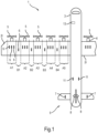
- some of the vortex generators 6 may be positioned in areas A1 to A5 of the upper surface of the wing 2I behind respective propellers 5 thus being exposed to the respective propeller washes.
- Other vortex generators 6 may be positioned in areas B1 to B4 next to the propellers 5, here: in areas B1 to B4 between the propellers 5.
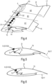
- all vortex generators 6 of the left wing 2I and the right wing 2r are individually movable through the upper surface of the respective wing 2I, 2r (i.e., through a respective opening) between a retracted state and a fully extended state, possibly including intermediate / partially extended states.
- the actuation of the vortex generators 6 is caused by operation of respective electric motors 12 (see Fig.2 and Fig.3 ) adapted to exclusively actuate the vortex generators 6. Operation of the electric motors 12 is controlled by an electric control unit 13 of the aircraft 1.
Landscapes
- Engineering & Computer Science (AREA)
- Aviation & Aerospace Engineering (AREA)
- Life Sciences & Earth Sciences (AREA)
- Sustainable Development (AREA)
- Sustainable Energy (AREA)
- Chemical & Material Sciences (AREA)
- Power Engineering (AREA)
- Transportation (AREA)
- Mechanical Engineering (AREA)
- Manufacturing & Machinery (AREA)
- Chemical Kinetics & Catalysis (AREA)
- Electrochemistry (AREA)
- General Chemical & Material Sciences (AREA)
- Combustion & Propulsion (AREA)
- Filling Or Discharging Of Gas Storage Vessels (AREA)
- Arrangement Or Mounting Of Propulsion Units For Vehicles (AREA)
- Toys (AREA)
Claims (10)
- Starrflügelflugzeug (1), mindestens aufweisend:- mehrere Propellerantriebseinheiten (4), die an jedem Flügel (21, 2r) angebracht sind,- mehrere Wirbelgeneratoren (6) an jedem Flügel (21, 2r), die durch eine Außenfläche des Flugzeugs (1) zwischen einem eingefahrenen Zustand und einem vollständig ausgefahrenen Zustand durch Elektromotoren (12) bewegbar sind, die ausschließlich dazu eingerichtet sind, die Wirbelgeneratoren (6, 7, 8, 11) zu betätigen, und umfassend- ein elektronisches Steuergerät (13), das zum Steuern eines Betriebs des mindestens einen Elektromotors (12) zur Betätigung der Wirbelgeneratoren (6, 7, 8, 11) eingerichtet ist,
wobei- von diesen Wirbelgeneratoren (6) Sätze von jeweils mindestens einem Wirbelgenerator (6) auf den Flügeln (21, 2r) hinter mindestens zwei Propellern (5) positioniert sind, und- der mindestens eine Wirbelgenerator (6) eines Satzes anders als der mindestens eine Wirbelgenerator (6) eines anderen Satzes betätigbar ist. - Flugzeug (1) nach Anspruch 1, wobei- mindestens einer der Sätze von Wirbelgeneratoren (6, 7, 8, 11) mindestens zwei Wirbelgeneratoren (6, 7, 8, 11) umfasst und- die Wirbelgeneratoren (6, 7, 8, 11) dieses Satzes auf die gleiche Weise betätigbar sind.
- Flugzeug (1) nach einem der vorhergehenden Ansprüche, wobei die Wirbelgeneratoren (6) eines Flügels (21, 2r) unabhängig von den Wirbelgeneratoren (6) des anderen Flügels (2r, 21) betätigbar sind.
- Flugzeug (1) nach einem der vorhergehenden Ansprüche, wobei mindestens zwei Wirbelgeneratoren (6) eines Flügels (21, 2r) unabhängig voneinander betätigbar sind.
- Flugzeug (1) nach einem der vorhergehenden Ansprüche, wobei eine Ausrichtung mindestens eines Wirbelgenerators (6) des mindestens einen Satzes von Wirbelgeneratoren (6), der hinter einem Propeller (5) positioniert ist, in Bezug auf eine Strömungsrichtung eines durch den Propeller (5) davor erzeugten Propellerstroms angewinkelt ist.
- Flugzeug (1) nach einem der vorhergehenden Ansprüche, umfassend mindestens einen Satz mit jeweils mindestens einem Wirbelgenerator (6), die seitlich versetzt zu den Propellern (5) an den Flügeln (21, 2r) positioniert sind, wobei die Wirbelgeneratoren (6) dieser Sätze anders als die Wirbelgeneratoren (6) von hinter den Propellern (5) positionierten Sätzen betätigbar sind.
- Flugzeug (1) nach einem der vorhergehenden Ansprüche, umfassend mindestens drei Propellerantriebseinheiten (4) pro Flügel (2r, 21).
- Flugzeug (1) nach einem der vorhergehenden Ansprüche, wobei die Betätigung mindestens eines Wirbelgenerators (6, 7, 8, 11) von mindestens einem der Parameter aus der folgenden Gruppe von Parametern abhängig ist:- Flugmodus und/oder Flugmanöver des Flugzeugs (1) ;- Geschwindigkeit des Flugzeugs (1);- Rollwinkel und/oder Rollgeschwindigkeit des Flugzeugs (1);- Schiebewinkel des Flugzeugs (1);- Anstellwinkel des Flugzeugs (1);- Grad der Auslenkung einer Steuerfläche (16, 17);- Steuerbefehl von einem Piloten oder einem Flugrechner.
- Flugzeug (1) nach einem der vorhergehenden Ansprüche, wobei die Betätigung mindestens eines Wirbelgenerators (6, 7, 8, 11) von einer Drosseleinstellung und/oder einer Propellerdrehzahl der mindestens einen Antriebseinheit (4) abhängig ist.
- Verfahren zum Betreiben eines Starrflügelflugzeugs (1) nach einem der vorhergehenden Ansprüche, wobei die Wirbelgeneratoren (6) der verschiedenen Sätze, die hinter den mindestens zwei Propellern positioniert sind, selektiv zwischen diesen Sätzen unter Verwendung der Elektromotoren (12) betätigt werden, die durch das elektronische Steuergerät (13) gesteuert werden.
Priority Applications (4)
| Application Number | Priority Date | Filing Date | Title |
|---|---|---|---|
| CN202280011029.2A CN116802118A (zh) | 2021-01-22 | 2022-01-20 | 具有可缩回式涡流发生器的飞行器 |
| PCT/EP2022/051230 WO2022157243A1 (en) | 2021-01-22 | 2022-01-20 | Aircraft having retractable vortex generators |
| US18/262,269 US12286215B2 (en) | 2021-01-22 | 2022-01-20 | Aircraft having retractable vortex generators |
| EP22700976.8A EP4281361B1 (de) | 2021-01-22 | 2022-01-20 | Flugzeug mit einziehbaren wirbelgeneratoren |
Applications Claiming Priority (1)
| Application Number | Priority Date | Filing Date | Title |
|---|---|---|---|
| EP21153046.4A EP4032810A1 (de) | 2021-01-22 | 2021-01-22 | Flugzeug mit elektrischem antriebsmodul |
Publications (2)
| Publication Number | Publication Date |
|---|---|
| EP4032807A1 EP4032807A1 (de) | 2022-07-27 |
| EP4032807B1 true EP4032807B1 (de) | 2025-02-26 |
Family
ID=74215746
Family Applications (4)
| Application Number | Title | Priority Date | Filing Date |
|---|---|---|---|
| EP21153046.4A Withdrawn EP4032810A1 (de) | 2021-01-22 | 2021-01-22 | Flugzeug mit elektrischem antriebsmodul |
| EP21173058.5A Active EP4032807B1 (de) | 2021-01-22 | 2021-05-10 | Flugzeug mit einziehbaren wirbelgeneratoren |
| EP21186951.6A Active EP4032811B1 (de) | 2021-01-22 | 2021-07-21 | Flugzeugantriebsmodul und flugzeug |
| EP22701243.2A Active EP4281370B1 (de) | 2021-01-22 | 2022-01-20 | Flugzeug mit elektrischem antriebsmodul |
Family Applications Before (1)
| Application Number | Title | Priority Date | Filing Date |
|---|---|---|---|
| EP21153046.4A Withdrawn EP4032810A1 (de) | 2021-01-22 | 2021-01-22 | Flugzeug mit elektrischem antriebsmodul |
Family Applications After (2)
| Application Number | Title | Priority Date | Filing Date |
|---|---|---|---|
| EP21186951.6A Active EP4032811B1 (de) | 2021-01-22 | 2021-07-21 | Flugzeugantriebsmodul und flugzeug |
| EP22701243.2A Active EP4281370B1 (de) | 2021-01-22 | 2022-01-20 | Flugzeug mit elektrischem antriebsmodul |
Country Status (4)
| Country | Link |
|---|---|
| US (1) | US20240308674A1 (de) |
| EP (4) | EP4032810A1 (de) |
| CN (1) | CN116867708A (de) |
| WO (1) | WO2022157241A1 (de) |
Families Citing this family (5)
| Publication number | Priority date | Publication date | Assignee | Title |
|---|---|---|---|---|
| WO2020060488A1 (en) * | 2018-09-18 | 2020-03-26 | H3 Dynamics Holdings Pte. Ltd. | Unmanned vehicle |
| US11577846B2 (en) * | 2020-02-21 | 2023-02-14 | ZeroAvia, Inc. | Modular electric powertrain conversion for aircraft |
| WO2022245427A2 (en) * | 2021-03-31 | 2022-11-24 | Zeroavia Ltd. | Refueling system for hydrogen fuel cell-powered aircraft |
| CN116834959B (zh) * | 2022-08-10 | 2025-09-26 | 北京纳米能源与系统研究所 | 运动体失速自驱动预警单元、预警方法和辅助设计方法 |
| WO2024089670A1 (en) | 2022-10-28 | 2024-05-02 | H3 Dynamics Holdings Pte. Ltd. | Frame device for a propulsion unit of a flight device |
Citations (1)
| Publication number | Priority date | Publication date | Assignee | Title |
|---|---|---|---|---|
| US7878457B2 (en) * | 2005-06-30 | 2011-02-01 | Bell Helicopter Textron, Inc. | Retractable vortex generator |
Family Cites Families (25)
| Publication number | Priority date | Publication date | Assignee | Title |
|---|---|---|---|---|
| GB1070723A (en) | 1963-01-16 | 1967-06-01 | Dehavilland Aircraft | Improvements in or relating to aircraft |
| US3777420A (en) * | 1972-08-04 | 1973-12-11 | Mattel Inc | Detachable power module for flying toy aircraft |
| US3960345A (en) * | 1975-05-16 | 1976-06-01 | Grumman Aerospace Corporation | Means to reduce and/or eliminate vortices, caused by wing body combinations |
| US4039161A (en) | 1975-10-16 | 1977-08-02 | Mcdonnell Douglas Corporation | Hidden vortex generators |
| US5106035A (en) * | 1989-12-29 | 1992-04-21 | Aurora Flight Sciences Corporation | Aircraft propulsion system using air liquefaction and storage |
| US5253828A (en) | 1992-07-17 | 1993-10-19 | The Board Of Regents Of The University Of Oklahoma | Concealable flap-actuated vortex generator |
| US6837465B2 (en) * | 2003-01-03 | 2005-01-04 | Orbital Research Inc | Flow control device and method of controlling flow |
| US6685143B1 (en) * | 2003-01-03 | 2004-02-03 | Orbital Research Inc. | Aircraft and missile forebody flow control device and method of controlling flow |
| US8846255B2 (en) * | 2007-04-20 | 2014-09-30 | Honeywell International Inc. | Fuel cells used to supplement power sources for aircraft equipment |
| US8087617B2 (en) * | 2008-08-15 | 2012-01-03 | The Boeing Company | Retractable nacelle chine |
| US8657238B2 (en) | 2011-07-05 | 2014-02-25 | The Boeing Company | Retractable vortex generator for reducing stall speed |
| US9505485B2 (en) | 2012-05-08 | 2016-11-29 | Lockheed Martin Corporation | Vortex generation |
| FR3002594B1 (fr) * | 2013-02-26 | 2016-09-30 | Snecma | Module de propulsion spatiale a propulsion electrique et chimique a propergol solide |
| DE102015101765A1 (de) | 2015-02-06 | 2016-08-11 | Airbus Operations Gmbh | Vortexgeneratoranordnung |
| GB2538982A (en) * | 2015-05-30 | 2016-12-07 | Victor Sills Nicholas | Self-contained, electric contra rotating propeller propulsion apparatus for aircraft |
| DE102015120958A1 (de) * | 2015-12-02 | 2017-06-08 | Dg Flugzeugbau Gmbh | Aktives Positionieren von Turbulatorflächenelementen |
| US10752343B2 (en) * | 2016-10-18 | 2020-08-25 | Sikorsky Aircraft Corporation | Electric propulsion system for a rotary wing aircraft |
| DE202016006522U1 (de) * | 2016-10-21 | 2016-12-01 | Askan Simon | Elektrische Aufstiegshilfe für Gleitschirme |
| WO2019241581A1 (en) * | 2018-06-16 | 2019-12-19 | Marinus Bernard Bosma | Electrically-powered aircraft with pod-mounted batteries |
| EP3814226A4 (de) | 2018-06-27 | 2022-03-23 | H3 Dynamics Holdings Pte. Ltd. | Verteiltes elektrisches energie-pod-netzwerk und zugehöriges elektrisch angetriebenes fahrzeug |
| WO2020060488A1 (en) * | 2018-09-18 | 2020-03-26 | H3 Dynamics Holdings Pte. Ltd. | Unmanned vehicle |
| ES2991416T3 (es) * | 2019-06-12 | 2024-12-03 | Airbus Operations Slu | Generador de vórtices de cuchilla |
| FR3097202B1 (fr) * | 2019-06-14 | 2024-02-23 | Airbus | Systeme autonome de propulsion a helice pour un aeronef, ledit systeme autonome de propulsion a helice comportant une pile a combustible |
| FR3097201B1 (fr) * | 2019-06-14 | 2024-02-23 | Airbus | Aeronef comportant une pluralite de systemes autonomes de propulsion a helice avec une pile a combustible |
| DE202020005286U1 (de) * | 2020-12-22 | 2021-02-10 | Christian Sturm | Integrierte Flugantriebseinheit |
-
2021
- 2021-01-22 EP EP21153046.4A patent/EP4032810A1/de not_active Withdrawn
- 2021-05-10 EP EP21173058.5A patent/EP4032807B1/de active Active
- 2021-07-21 EP EP21186951.6A patent/EP4032811B1/de active Active
-
2022
- 2022-01-20 WO PCT/EP2022/051227 patent/WO2022157241A1/en not_active Ceased
- 2022-01-20 US US18/262,257 patent/US20240308674A1/en active Pending
- 2022-01-20 CN CN202280011030.5A patent/CN116867708A/zh active Pending
- 2022-01-20 EP EP22701243.2A patent/EP4281370B1/de active Active
Patent Citations (1)
| Publication number | Priority date | Publication date | Assignee | Title |
|---|---|---|---|---|
| US7878457B2 (en) * | 2005-06-30 | 2011-02-01 | Bell Helicopter Textron, Inc. | Retractable vortex generator |
Also Published As
| Publication number | Publication date |
|---|---|
| CN116867708A (zh) | 2023-10-10 |
| EP4032811A1 (de) | 2022-07-27 |
| EP4032807A1 (de) | 2022-07-27 |
| EP4032811B1 (de) | 2025-03-05 |
| EP4281370B1 (de) | 2024-10-23 |
| WO2022157241A1 (en) | 2022-07-28 |
| EP4281370A1 (de) | 2023-11-29 |
| EP4032810A1 (de) | 2022-07-27 |
| US20240308674A1 (en) | 2024-09-19 |
Similar Documents
| Publication | Publication Date | Title |
|---|---|---|
| EP4032807B1 (de) | Flugzeug mit einziehbaren wirbelgeneratoren | |
| US6079672A (en) | Aileron for fixed wing aircraft | |
| US11787526B2 (en) | System and method for lift augmentation of aircraft wings | |
| US7367530B2 (en) | Aerospace vehicle yaw generating systems and associated methods | |
| US20050242234A1 (en) | Lifters, methods of flight control and maneuver load alleviation | |
| US12570395B2 (en) | Winglet control surfaces and methods for use therewith | |
| US9561844B2 (en) | System and method for an air vehicle | |
| US20090230240A1 (en) | Aerodynamic fan control effector | |
| US10926868B1 (en) | Distributed leading-edge lifting surface slat and associated electric ducted fans for fixed lifting surface aircraft | |
| US11685516B2 (en) | Passive gust-load-alleviation device | |
| CN116802118A (zh) | 具有可缩回式涡流发生器的飞行器 | |
| US11639217B2 (en) | Procedure for maneuvering a hybrid aerodyne of VTOL or STOL | |
| GB2574603A (en) | Vertical stabilizer for an aircraft | |
| US6543720B2 (en) | Directional control and aerofoil system for aircraft | |
| EP4281361B1 (de) | Flugzeug mit einziehbaren wirbelgeneratoren | |
| EP0257123B1 (de) | Aktives Steuersystem eines Flugzeuges mit biegsamem Flügel | |
| US12049299B2 (en) | Airfoil system | |
| GB2634317A (en) | Aircraft wing with leading edge spoiler | |
| EP4011767B1 (de) | Drehflügelflugzeug mit einer stabilisatoranordnung | |
| EP4342789B1 (de) | Flugsteuerfläche | |
| GB2345894A (en) | A method of roll control for aeroplanes | |
| WO2025128383A1 (en) | Craft with improved motor pod | |
| Gato et al. | Innovative aerodynamics-The sensible way of restoring growth capability to the EA-6B Prowler | |
| GB2636846A (en) | An aircraft wing with a wing tip device | |
| EP4680529A2 (de) | Luftgeschwindigkeitsregelung in einem flugzeug mit geblasenen flügeln |
Legal Events
| Date | Code | Title | Description |
|---|---|---|---|
| PUAI | Public reference made under article 153(3) epc to a published international application that has entered the european phase |
Free format text: ORIGINAL CODE: 0009012 |
|
| STAA | Information on the status of an ep patent application or granted ep patent |
Free format text: STATUS: THE APPLICATION HAS BEEN PUBLISHED |
|
| AK | Designated contracting states |
Kind code of ref document: A1 Designated state(s): AL AT BE BG CH CY CZ DE DK EE ES FI FR GB GR HR HU IE IS IT LI LT LU LV MC MK MT NL NO PL PT RO RS SE SI SK SM TR |
|
| STAA | Information on the status of an ep patent application or granted ep patent |
Free format text: STATUS: REQUEST FOR EXAMINATION WAS MADE |
|
| 17P | Request for examination filed |
Effective date: 20230126 |
|
| RBV | Designated contracting states (corrected) |
Designated state(s): AL AT BE BG CH CY CZ DE DK EE ES FI FR GB GR HR HU IE IS IT LI LT LU LV MC MK MT NL NO PL PT RO RS SE SI SK SM TR |
|
| STAA | Information on the status of an ep patent application or granted ep patent |
Free format text: STATUS: EXAMINATION IS IN PROGRESS |
|
| 17Q | First examination report despatched |
Effective date: 20231205 |
|
| 17Q | First examination report despatched |
Effective date: 20240112 |
|
| GRAP | Despatch of communication of intention to grant a patent |
Free format text: ORIGINAL CODE: EPIDOSNIGR1 |
|
| STAA | Information on the status of an ep patent application or granted ep patent |
Free format text: STATUS: GRANT OF PATENT IS INTENDED |
|
| RIC1 | Information provided on ipc code assigned before grant |
Ipc: B64D 27/31 20240101ALI20240918BHEP Ipc: B64C 23/06 20060101AFI20240918BHEP |
|
| INTG | Intention to grant announced |
Effective date: 20241011 |
|
| GRAS | Grant fee paid |
Free format text: ORIGINAL CODE: EPIDOSNIGR3 |
|
| GRAA | (expected) grant |
Free format text: ORIGINAL CODE: 0009210 |
|
| STAA | Information on the status of an ep patent application or granted ep patent |
Free format text: STATUS: THE PATENT HAS BEEN GRANTED |
|
| AK | Designated contracting states |
Kind code of ref document: B1 Designated state(s): AL AT BE BG CH CY CZ DE DK EE ES FI FR GB GR HR HU IE IS IT LI LT LU LV MC MK MT NL NO PL PT RO RS SE SI SK SM TR |
|
| REG | Reference to a national code |
Ref country code: GB Ref legal event code: FG4D |
|
| REG | Reference to a national code |
Ref country code: CH Ref legal event code: EP |
|
| REG | Reference to a national code |
Ref country code: DE Ref legal event code: R096 Ref document number: 602021026636 Country of ref document: DE |
|
| REG | Reference to a national code |
Ref country code: IE Ref legal event code: FG4D |
|
| REG | Reference to a national code |
Ref country code: NL Ref legal event code: MP Effective date: 20250226 |
|
| PG25 | Lapsed in a contracting state [announced via postgrant information from national office to epo] |
Ref country code: RS Free format text: LAPSE BECAUSE OF FAILURE TO SUBMIT A TRANSLATION OF THE DESCRIPTION OR TO PAY THE FEE WITHIN THE PRESCRIBED TIME-LIMIT Effective date: 20250526 |
|
| PG25 | Lapsed in a contracting state [announced via postgrant information from national office to epo] |
Ref country code: FI Free format text: LAPSE BECAUSE OF FAILURE TO SUBMIT A TRANSLATION OF THE DESCRIPTION OR TO PAY THE FEE WITHIN THE PRESCRIBED TIME-LIMIT Effective date: 20250226 |
|
| PG25 | Lapsed in a contracting state [announced via postgrant information from national office to epo] |
Ref country code: PL Free format text: LAPSE BECAUSE OF FAILURE TO SUBMIT A TRANSLATION OF THE DESCRIPTION OR TO PAY THE FEE WITHIN THE PRESCRIBED TIME-LIMIT Effective date: 20250226 |
|
| PGFP | Annual fee paid to national office [announced via postgrant information from national office to epo] |
Ref country code: DE Payment date: 20250528 Year of fee payment: 5 |
|
| PG25 | Lapsed in a contracting state [announced via postgrant information from national office to epo] |
Ref country code: ES Free format text: LAPSE BECAUSE OF FAILURE TO SUBMIT A TRANSLATION OF THE DESCRIPTION OR TO PAY THE FEE WITHIN THE PRESCRIBED TIME-LIMIT Effective date: 20250226 |
|
| PGFP | Annual fee paid to national office [announced via postgrant information from national office to epo] |
Ref country code: GB Payment date: 20250527 Year of fee payment: 5 |
|
| REG | Reference to a national code |
Ref country code: LT Ref legal event code: MG9D |
|
| PG25 | Lapsed in a contracting state [announced via postgrant information from national office to epo] |
Ref country code: NO Free format text: LAPSE BECAUSE OF FAILURE TO SUBMIT A TRANSLATION OF THE DESCRIPTION OR TO PAY THE FEE WITHIN THE PRESCRIBED TIME-LIMIT Effective date: 20250526 Ref country code: IS Free format text: LAPSE BECAUSE OF FAILURE TO SUBMIT A TRANSLATION OF THE DESCRIPTION OR TO PAY THE FEE WITHIN THE PRESCRIBED TIME-LIMIT Effective date: 20250626 |
|
| PG25 | Lapsed in a contracting state [announced via postgrant information from national office to epo] |
Ref country code: NL Free format text: LAPSE BECAUSE OF FAILURE TO SUBMIT A TRANSLATION OF THE DESCRIPTION OR TO PAY THE FEE WITHIN THE PRESCRIBED TIME-LIMIT Effective date: 20250226 |
|
| PG25 | Lapsed in a contracting state [announced via postgrant information from national office to epo] |
Ref country code: HR Free format text: LAPSE BECAUSE OF FAILURE TO SUBMIT A TRANSLATION OF THE DESCRIPTION OR TO PAY THE FEE WITHIN THE PRESCRIBED TIME-LIMIT Effective date: 20250226 |
|
| PG25 | Lapsed in a contracting state [announced via postgrant information from national office to epo] |
Ref country code: LV Free format text: LAPSE BECAUSE OF FAILURE TO SUBMIT A TRANSLATION OF THE DESCRIPTION OR TO PAY THE FEE WITHIN THE PRESCRIBED TIME-LIMIT Effective date: 20250226 Ref country code: PT Free format text: LAPSE BECAUSE OF FAILURE TO SUBMIT A TRANSLATION OF THE DESCRIPTION OR TO PAY THE FEE WITHIN THE PRESCRIBED TIME-LIMIT Effective date: 20250626 |
|
| PGFP | Annual fee paid to national office [announced via postgrant information from national office to epo] |
Ref country code: FR Payment date: 20250523 Year of fee payment: 5 |
|
| PG25 | Lapsed in a contracting state [announced via postgrant information from national office to epo] |
Ref country code: GR Free format text: LAPSE BECAUSE OF FAILURE TO SUBMIT A TRANSLATION OF THE DESCRIPTION OR TO PAY THE FEE WITHIN THE PRESCRIBED TIME-LIMIT Effective date: 20250527 Ref country code: BG Free format text: LAPSE BECAUSE OF FAILURE TO SUBMIT A TRANSLATION OF THE DESCRIPTION OR TO PAY THE FEE WITHIN THE PRESCRIBED TIME-LIMIT Effective date: 20250226 |
|
| REG | Reference to a national code |
Ref country code: AT Ref legal event code: MK05 Ref document number: 1770429 Country of ref document: AT Kind code of ref document: T Effective date: 20250226 |
|
| PG25 | Lapsed in a contracting state [announced via postgrant information from national office to epo] |
Ref country code: SE Free format text: LAPSE BECAUSE OF FAILURE TO SUBMIT A TRANSLATION OF THE DESCRIPTION OR TO PAY THE FEE WITHIN THE PRESCRIBED TIME-LIMIT Effective date: 20250226 |
|
| P01 | Opt-out of the competence of the unified patent court (upc) registered |
Free format text: CASE NUMBER: UPC_APP_4143_4032807/2025 Effective date: 20250825 |
|
| PG25 | Lapsed in a contracting state [announced via postgrant information from national office to epo] |
Ref country code: SM Free format text: LAPSE BECAUSE OF FAILURE TO SUBMIT A TRANSLATION OF THE DESCRIPTION OR TO PAY THE FEE WITHIN THE PRESCRIBED TIME-LIMIT Effective date: 20250226 |
|
| PG25 | Lapsed in a contracting state [announced via postgrant information from national office to epo] |
Ref country code: DK Free format text: LAPSE BECAUSE OF FAILURE TO SUBMIT A TRANSLATION OF THE DESCRIPTION OR TO PAY THE FEE WITHIN THE PRESCRIBED TIME-LIMIT Effective date: 20250226 |
|
| REG | Reference to a national code |
Ref country code: DE Ref legal event code: R082 Ref document number: 602021026636 Country of ref document: DE Representative=s name: SCHULZE, MARK, DIPL.-PHYS. DR.RER.NAT., DE |
|
| PG25 | Lapsed in a contracting state [announced via postgrant information from national office to epo] |
Ref country code: IT Free format text: LAPSE BECAUSE OF FAILURE TO SUBMIT A TRANSLATION OF THE DESCRIPTION OR TO PAY THE FEE WITHIN THE PRESCRIBED TIME-LIMIT Effective date: 20250226 |
|
| PG25 | Lapsed in a contracting state [announced via postgrant information from national office to epo] |
Ref country code: AT Free format text: LAPSE BECAUSE OF FAILURE TO SUBMIT A TRANSLATION OF THE DESCRIPTION OR TO PAY THE FEE WITHIN THE PRESCRIBED TIME-LIMIT Effective date: 20250226 |
|
| PG25 | Lapsed in a contracting state [announced via postgrant information from national office to epo] |
Ref country code: EE Free format text: LAPSE BECAUSE OF FAILURE TO SUBMIT A TRANSLATION OF THE DESCRIPTION OR TO PAY THE FEE WITHIN THE PRESCRIBED TIME-LIMIT Effective date: 20250226 Ref country code: CZ Free format text: LAPSE BECAUSE OF FAILURE TO SUBMIT A TRANSLATION OF THE DESCRIPTION OR TO PAY THE FEE WITHIN THE PRESCRIBED TIME-LIMIT Effective date: 20250226 |
|
| PG25 | Lapsed in a contracting state [announced via postgrant information from national office to epo] |
Ref country code: RO Free format text: LAPSE BECAUSE OF FAILURE TO SUBMIT A TRANSLATION OF THE DESCRIPTION OR TO PAY THE FEE WITHIN THE PRESCRIBED TIME-LIMIT Effective date: 20250226 |
|
| PG25 | Lapsed in a contracting state [announced via postgrant information from national office to epo] |
Ref country code: SK Free format text: LAPSE BECAUSE OF FAILURE TO SUBMIT A TRANSLATION OF THE DESCRIPTION OR TO PAY THE FEE WITHIN THE PRESCRIBED TIME-LIMIT Effective date: 20250226 |
|
| REG | Reference to a national code |
Ref country code: DE Ref legal event code: R097 Ref document number: 602021026636 Country of ref document: DE |
|
| REG | Reference to a national code |
Ref country code: CH Ref legal event code: H13 Free format text: ST27 STATUS EVENT CODE: U-0-0-H10-H13 (AS PROVIDED BY THE NATIONAL OFFICE) Effective date: 20251223 |
|
| PLBE | No opposition filed within time limit |
Free format text: ORIGINAL CODE: 0009261 |
|
| STAA | Information on the status of an ep patent application or granted ep patent |
Free format text: STATUS: NO OPPOSITION FILED WITHIN TIME LIMIT |
|
| PG25 | Lapsed in a contracting state [announced via postgrant information from national office to epo] |
Ref country code: LU Free format text: LAPSE BECAUSE OF NON-PAYMENT OF DUE FEES Effective date: 20250510 |
|
| PG25 | Lapsed in a contracting state [announced via postgrant information from national office to epo] |
Ref country code: CH Free format text: LAPSE BECAUSE OF NON-PAYMENT OF DUE FEES Effective date: 20250531 |
|
| REG | Reference to a national code |
Ref country code: BE Ref legal event code: MM Effective date: 20250531 |
|
| PG25 | Lapsed in a contracting state [announced via postgrant information from national office to epo] |
Ref country code: MC Free format text: LAPSE BECAUSE OF FAILURE TO SUBMIT A TRANSLATION OF THE DESCRIPTION OR TO PAY THE FEE WITHIN THE PRESCRIBED TIME-LIMIT Effective date: 20250226 |
|
| 26N | No opposition filed |
Effective date: 20251127 |
|
| PG25 | Lapsed in a contracting state [announced via postgrant information from national office to epo] |
Ref country code: IE Free format text: LAPSE BECAUSE OF NON-PAYMENT OF DUE FEES Effective date: 20250510 |
|
| PG25 | Lapsed in a contracting state [announced via postgrant information from national office to epo] |
Ref country code: BE Free format text: LAPSE BECAUSE OF NON-PAYMENT OF DUE FEES Effective date: 20250531 |