EP4032811A1 - Flugzeugantriebsmodul und flugzeug - Google Patents
Flugzeugantriebsmodul und flugzeug Download PDFInfo
- Publication number
- EP4032811A1 EP4032811A1 EP21186951.6A EP21186951A EP4032811A1 EP 4032811 A1 EP4032811 A1 EP 4032811A1 EP 21186951 A EP21186951 A EP 21186951A EP 4032811 A1 EP4032811 A1 EP 4032811A1
- Authority
- EP
- European Patent Office
- Prior art keywords
- propulsion module
- component
- aircraft
- module
- axle
- Prior art date
- Legal status (The legal status is an assumption and is not a legal conclusion. Google has not performed a legal analysis and makes no representation as to the accuracy of the status listed.)
- Granted
Links
Images


Classifications
-
- B—PERFORMING OPERATIONS; TRANSPORTING
- B60—VEHICLES IN GENERAL
- B60L—PROPULSION OF ELECTRICALLY-PROPELLED VEHICLES; SUPPLYING ELECTRIC POWER FOR AUXILIARY EQUIPMENT OF ELECTRICALLY-PROPELLED VEHICLES; ELECTRODYNAMIC BRAKE SYSTEMS FOR VEHICLES IN GENERAL; MAGNETIC SUSPENSION OR LEVITATION FOR VEHICLES; MONITORING OPERATING VARIABLES OF ELECTRICALLY-PROPELLED VEHICLES; ELECTRIC SAFETY DEVICES FOR ELECTRICALLY-PROPELLED VEHICLES
- B60L50/00—Electric propulsion with power supplied within the vehicle
- B60L50/50—Electric propulsion with power supplied within the vehicle using propulsion power supplied by batteries or fuel cells
- B60L50/70—Electric propulsion with power supplied within the vehicle using propulsion power supplied by batteries or fuel cells using power supplied by fuel cells
- B60L50/71—Arrangement of fuel cells within vehicles specially adapted for electric vehicles
-
- B—PERFORMING OPERATIONS; TRANSPORTING
- B60—VEHICLES IN GENERAL
- B60L—PROPULSION OF ELECTRICALLY-PROPELLED VEHICLES; SUPPLYING ELECTRIC POWER FOR AUXILIARY EQUIPMENT OF ELECTRICALLY-PROPELLED VEHICLES; ELECTRODYNAMIC BRAKE SYSTEMS FOR VEHICLES IN GENERAL; MAGNETIC SUSPENSION OR LEVITATION FOR VEHICLES; MONITORING OPERATING VARIABLES OF ELECTRICALLY-PROPELLED VEHICLES; ELECTRIC SAFETY DEVICES FOR ELECTRICALLY-PROPELLED VEHICLES
- B60L58/00—Methods or circuit arrangements for monitoring or controlling batteries or fuel cells, specially adapted for electric vehicles
- B60L58/40—Methods or circuit arrangements for monitoring or controlling batteries or fuel cells, specially adapted for electric vehicles for controlling a combination of batteries and fuel cells
-
- B—PERFORMING OPERATIONS; TRANSPORTING
- B64—AIRCRAFT; AVIATION; COSMONAUTICS
- B64C—AEROPLANES; HELICOPTERS
- B64C23/00—Influencing air flow over aircraft surfaces, not otherwise provided for
- B64C23/06—Influencing air flow over aircraft surfaces, not otherwise provided for by generating vortices
-
- B—PERFORMING OPERATIONS; TRANSPORTING
- B64—AIRCRAFT; AVIATION; COSMONAUTICS
- B64D—EQUIPMENT FOR FITTING IN OR TO AIRCRAFT; FLIGHT SUITS; PARACHUTES; ARRANGEMENT OR MOUNTING OF POWER PLANTS OR PROPULSION TRANSMISSIONS IN AIRCRAFT
- B64D27/00—Arrangement or mounting of power plants in aircraft; Aircraft characterised by the type or position of power plants
- B64D27/02—Aircraft characterised by the type or position of power plants
- B64D27/30—Aircraft characterised by electric power plants
- B64D27/31—Aircraft characterised by electric power plants within, or attached to, wings
-
- B—PERFORMING OPERATIONS; TRANSPORTING
- B64—AIRCRAFT; AVIATION; COSMONAUTICS
- B64D—EQUIPMENT FOR FITTING IN OR TO AIRCRAFT; FLIGHT SUITS; PARACHUTES; ARRANGEMENT OR MOUNTING OF POWER PLANTS OR PROPULSION TRANSMISSIONS IN AIRCRAFT
- B64D27/00—Arrangement or mounting of power plants in aircraft; Aircraft characterised by the type or position of power plants
- B64D27/02—Aircraft characterised by the type or position of power plants
- B64D27/30—Aircraft characterised by electric power plants
- B64D27/34—All-electric aircraft
-
- B—PERFORMING OPERATIONS; TRANSPORTING
- B64—AIRCRAFT; AVIATION; COSMONAUTICS
- B64D—EQUIPMENT FOR FITTING IN OR TO AIRCRAFT; FLIGHT SUITS; PARACHUTES; ARRANGEMENT OR MOUNTING OF POWER PLANTS OR PROPULSION TRANSMISSIONS IN AIRCRAFT
- B64D27/00—Arrangement or mounting of power plants in aircraft; Aircraft characterised by the type or position of power plants
- B64D27/02—Aircraft characterised by the type or position of power plants
- B64D27/30—Aircraft characterised by electric power plants
- B64D27/35—Arrangements for on-board electric energy production, distribution, recovery or storage
- B64D27/355—Arrangements for on-board electric energy production, distribution, recovery or storage using fuel cells
-
- B—PERFORMING OPERATIONS; TRANSPORTING
- B64—AIRCRAFT; AVIATION; COSMONAUTICS
- B64D—EQUIPMENT FOR FITTING IN OR TO AIRCRAFT; FLIGHT SUITS; PARACHUTES; ARRANGEMENT OR MOUNTING OF POWER PLANTS OR PROPULSION TRANSMISSIONS IN AIRCRAFT
- B64D31/00—Power plant control systems; Arrangement of power plant control systems in aircraft
- B64D31/16—Power plant control systems; Arrangement of power plant control systems in aircraft for electric power plants
-
- B—PERFORMING OPERATIONS; TRANSPORTING
- B64—AIRCRAFT; AVIATION; COSMONAUTICS
- B64D—EQUIPMENT FOR FITTING IN OR TO AIRCRAFT; FLIGHT SUITS; PARACHUTES; ARRANGEMENT OR MOUNTING OF POWER PLANTS OR PROPULSION TRANSMISSIONS IN AIRCRAFT
- B64D37/00—Arrangements in connection with fuel supply for power plant
- B64D37/30—Fuel systems for specific fuels
-
- B—PERFORMING OPERATIONS; TRANSPORTING
- B64—AIRCRAFT; AVIATION; COSMONAUTICS
- B64U—UNMANNED AERIAL VEHICLES [UAV]; EQUIPMENT THEREFOR
- B64U50/00—Propulsion; Power supply
- B64U50/10—Propulsion
- B64U50/19—Propulsion using electrically powered motors
-
- H—ELECTRICITY
- H01—ELECTRIC ELEMENTS
- H01M—PROCESSES OR MEANS, e.g. BATTERIES, FOR THE DIRECT CONVERSION OF CHEMICAL ENERGY INTO ELECTRICAL ENERGY
- H01M8/00—Fuel cells; Manufacture thereof
- H01M8/04—Auxiliary arrangements, e.g. for control of pressure or for circulation of fluids
- H01M8/04082—Arrangements for control of reactant parameters, e.g. pressure or concentration
- H01M8/04089—Arrangements for control of reactant parameters, e.g. pressure or concentration of gaseous reactants
-
- H—ELECTRICITY
- H01—ELECTRIC ELEMENTS
- H01M—PROCESSES OR MEANS, e.g. BATTERIES, FOR THE DIRECT CONVERSION OF CHEMICAL ENERGY INTO ELECTRICAL ENERGY
- H01M8/00—Fuel cells; Manufacture thereof
- H01M8/04—Auxiliary arrangements, e.g. for control of pressure or for circulation of fluids
- H01M8/04082—Arrangements for control of reactant parameters, e.g. pressure or concentration
- H01M8/04201—Reactant storage and supply, e.g. means for feeding, pipes
-
- B—PERFORMING OPERATIONS; TRANSPORTING
- B60—VEHICLES IN GENERAL
- B60L—PROPULSION OF ELECTRICALLY-PROPELLED VEHICLES; SUPPLYING ELECTRIC POWER FOR AUXILIARY EQUIPMENT OF ELECTRICALLY-PROPELLED VEHICLES; ELECTRODYNAMIC BRAKE SYSTEMS FOR VEHICLES IN GENERAL; MAGNETIC SUSPENSION OR LEVITATION FOR VEHICLES; MONITORING OPERATING VARIABLES OF ELECTRICALLY-PROPELLED VEHICLES; ELECTRIC SAFETY DEVICES FOR ELECTRICALLY-PROPELLED VEHICLES
- B60L2200/00—Type of vehicles
- B60L2200/10—Air crafts
-
- H—ELECTRICITY
- H01—ELECTRIC ELEMENTS
- H01M—PROCESSES OR MEANS, e.g. BATTERIES, FOR THE DIRECT CONVERSION OF CHEMICAL ENERGY INTO ELECTRICAL ENERGY
- H01M2220/00—Batteries for particular applications
- H01M2220/20—Batteries in motive systems, e.g. vehicle, ship, plane
-
- H—ELECTRICITY
- H01—ELECTRIC ELEMENTS
- H01M—PROCESSES OR MEANS, e.g. BATTERIES, FOR THE DIRECT CONVERSION OF CHEMICAL ENERGY INTO ELECTRICAL ENERGY
- H01M2250/00—Fuel cells for particular applications; Specific features of fuel cell system
- H01M2250/20—Fuel cells in motive systems, e.g. vehicle, ship, plane
-
- Y—GENERAL TAGGING OF NEW TECHNOLOGICAL DEVELOPMENTS; GENERAL TAGGING OF CROSS-SECTIONAL TECHNOLOGIES SPANNING OVER SEVERAL SECTIONS OF THE IPC; TECHNICAL SUBJECTS COVERED BY FORMER USPC CROSS-REFERENCE ART COLLECTIONS [XRACs] AND DIGESTS
- Y02—TECHNOLOGIES OR APPLICATIONS FOR MITIGATION OR ADAPTATION AGAINST CLIMATE CHANGE
- Y02T—CLIMATE CHANGE MITIGATION TECHNOLOGIES RELATED TO TRANSPORTATION
- Y02T50/00—Aeronautics or air transport
- Y02T50/10—Drag reduction
-
- Y—GENERAL TAGGING OF NEW TECHNOLOGICAL DEVELOPMENTS; GENERAL TAGGING OF CROSS-SECTIONAL TECHNOLOGIES SPANNING OVER SEVERAL SECTIONS OF THE IPC; TECHNICAL SUBJECTS COVERED BY FORMER USPC CROSS-REFERENCE ART COLLECTIONS [XRACs] AND DIGESTS
- Y02—TECHNOLOGIES OR APPLICATIONS FOR MITIGATION OR ADAPTATION AGAINST CLIMATE CHANGE
- Y02T—CLIMATE CHANGE MITIGATION TECHNOLOGIES RELATED TO TRANSPORTATION
- Y02T90/00—Enabling technologies or technologies with a potential or indirect contribution to GHG emissions mitigation
- Y02T90/40—Application of hydrogen technology to transportation, e.g. using fuel cells
Definitions
- the present invention relates to an aircraft propulsion module comprising a hydrogen storage system, at least one electrochemical converter connected to the hydrogen storage system, wherein the at least one electrochemical converter is adapted to convert hydrogen supplied from the hydrogen storage system into electric energy, and at least one electric motor electrically connected to the at least one electrochemical converter, wherein the electric motor is adapted to generate thrust.
- the present invention also relates to an aircraft comprising at least one such propulsion module.
- the present invention further relates to a method of operating such a propulsion module.
- modules may be defined as airborne equipment anchored to a dedicated point on the aircraft's structure. Mainly used in the military field, they can provide different functions such as extension of the fuel capacity or weapons and external sensors carriage. On the Clip-Air project, presented by the autoimmune Polytechnique Fédérale de Lausanne in June 2013, modules could even represent independent cabins to transport passengers.
- WO 2020/003181 A1 discloses a pod for moving a vehicle and also provides a network of interchangeable pods.
- the pod includes an energy storage and powering machine and a nacelle.
- the nacelle includes an enclosure for surrounding the energy storage and powering machine and a joining structure for attaching the enclosure to the vehicle.
- the energy storage and the powering machine include a power generation module, a propulsion module, and an electronics module.
- the propulsion module includes an electric motor with a propeller module.
- the electronics module is provided for activating the power generation module to provide electrical energy to the electric motor, wherein the electric motor actuates the propeller module for moving the vehicle.
- an aircraft propulsion module comprising at least
- the removable propulsion module provides an independent, autonomous, and removable part ("module") for thrust generation which, in principle, can be adapted on any aircraft.
- the propulsion module is not embedded in the wing or the fuselage of the aircraft but can be added to the aircraft structure, e.g., a wing, by means of a simple fastening interface.
- the removable propulsion module comprises all means for aircraft propulsion and only needs to be mechanically attached to the aircraft (e.g., by at least one fastening means) and, potentially, can be brought in data communication with the aircraft (e.g., by being equipped with a wired and/or a wireless communication interface) to receive data for its operation and potentially to feed back status data like a fuel level, possible defects, etc.
- the hydrogen storage system may be adapted to store gaseous, liquid and/or solid hydrogen.
- the hydrogen storage system may comprise at least one hydrogen storage unit for physically storing hydrogen, e.g., a hydrogen tank for storing gaseous and/or liquid hydrogen, a dedicated material (e.g., metal hydride, porous carbon, etc.) for chemical or physical solid hydrogen storage, etc.
- the hydrogen storage system may further comprise at least one piping network dedicated to supply the at least one electrochemical converter with hydrogen coming from the hydrogen storage unit and/or at least one piping network which allows for external hydrogen refuelling.
- the electrochemical converter comprises at least one fuel cell.
- the electric motor is supplied with electric energy from the electrochemical converter.
- the electric motor is connected to and thus drives at least one propeller or at least one ducted fan, or even other propulsion means.
- the propulsion module comprises at least one further means ("electric load") using or storing the electric energy generated by the electrochemical converter.
- an electric load may, for example, include at least one further electric motor (e.g., for moving retractable vortex generators), at least one electric actuator of the separation means (which may also be an electric motor), at least one electric or electronic control means, at least one voltage / current converter, at least one valve, at least one electric switch, at least one lamp, etc.
- at least one voltage / current converter is a DC/DC converter, an AC/DC converter, and/or a DC/AC converter.
- the at least one electric or electronic control means may comprise or be at least one control unit adapted to control operation of at least one of the components of the propulsion module, especially an energy, power, and/or torque management unit, etc.
- the at least one electric or electronic control means may comprise a microcontroller, ASIC, FPGA, and/or a data communication interface, e.g., an ethernet interface, etc.
- the propulsion module further comprises at least one electric energy storage unit comprising or being, e.g., at least one rechargeable battery, and/or at least one super capacitor (e.g., a gold cap), etc.
- at least one electric load of the propulsion module can be supplied with electric energy even if the electrochemical converter generates not enough power (e.g., during peak demand) or is faulty. This also enhances operational safety.
- the electric energy storage unit is electrically connected to the electrochemical converter. This gives the advantage that the electric energy storage unit can be charged in flight if the electric power generated by the electrochemical converter is greater than the electric power used by the other components.
- Operation of the propulsion module under normal conditions may comprise at least one operational phase out of the following group of phases:
- the propulsion module further comprises at least one cooling system.
- the cooling system may be an active and/or a passive cooling system (or any other form of cooling) and may, in case of an active cooling system, thus also regarded to be an electric load.
- the cooling system may comprise a heat exchanger.
- the propulsion module comprises a first part and a second part, each of which comprise a respective fairing.
- the first part and the second part can be separated from each other, e.g., by actuation of the separation means and/or during maintenance.
- the first part comprises the power generating function(s) of the propulsion module.
- the first part comprises at least the at least one electrochemical converter and the at least one electric motor. This gives the advantage that maintenance of components of the first part can be carried out separately from refilling which saves time.
- the first part may also comprise the electric energy storage unit and the cooling system.
- the fairing of the first part gives the advantage that it reduces drag penalty, in particular if the first part is a front part located in front of a wing profile (see also below).
- the shape of the fairing of the first part is continuous with the wing profile at the contact area, i.e., there are no sharp changes at the transition between the fairing of the first part and the wing profile.
- the fairing protects the components located in the first part from external damages.
- a thrust vector of the propulsion module is aligned with the chord of the wing.
- the first part comprises a support in form of a frame, that is surrounded by the fairing.
- Fixed / attached to the frame is at least one of the components of the first part, e.g., the at least one electric motor, the at least one electric energy storage unit, and/or the at least one electrochemical converter.
- Other components of the first part like the cooling system etc. may also be attached / fixed to the frame.
- the second part comprises the hydrogen storage system.
- the second part may comprise at least one hydrogen storage unit in its fairing, e.g., a hydrogen tank, and at least one piping network.
- fairing protects the hydrogen storage unit and the at least one piping network from external damages.
- the fairing also creates a mechanical link between the wing and the hydrogen storage unit without having to modify the hydrogen storage unit. This is particularly advantageous if an off-the-shelf hydrogen storage unit is used.
- the first part and second part are connected via at least one fluid connection line (e.g., a feeding pipe / tube for flowing hydrogen fluid from the second part to the first part).
- Electric connection lines may be connected to different electronics of the first and/or second part of the module, e.g., for monitoring purposes.
- Mechanical connection lines may be mechanically connected to certain components and may, e.g., be thin metal wires, plastic cables etc.
- fluid connection lines e.g., for supplying hydrogen
- electric connection lines e.g., for supplying voltage, sending electrical signals, and/or data communication
- mechanical connection lines e.g., of a components separation means
- the first part may be a front part and the second part is a rear part positioned aft of the front part. This enables a particularly compact design.
- first part is attached to the second part and/or to the wing. It is an embodiment that the second part is attached to the first part and/or to the wing. If the second part is attached to the wing, it may be positioned underneath the wing profile. It is an embodiment that the first part is only attached to the second part, and the second part is only attached to the wing.
- the at least one separation means being adapted to separate at least one component of the propulsion module comprises separating / detaching this at least one component from the support it is attached to.
- the actuation of the at least one separation means is remotely controllable, e.g., by a pilot or automatically via a control system.
- the support may generally be any suitable structure adapted to attach at least one component, in particular the frame of the first part of the propulsion module.
- the at least one component separable by actuation of the separation means comprises or is the at least one electrochemical converter, the at least one electric energy storage unit, and/or the at least one electric motor.
- the at least one component separable by actuation of the separation means comprises or is the at least one electrochemical converter, the at least one electric energy storage unit, and/or the at least one electric motor.
- the support may also be the other part of the propulsion module and or even the wing. This allows separating the first part and/or the second part as a whole. It is an embodiment that the first part and the second part are disconnectable from each other during operation of the propulsion module, e.g., in flight. This gives the advantage that, if one of the two parts is damaged or fails, subsequent damage or failure of the other part can be avoided even in flight. It is an embodiment that the first part and the second part are disconnectable from each other during inoperation of the module, e.g., on ground, e.g., for parts swap, maintenance, or repair.
- the first part is separable from the (rest of the) aircraft by the at least one separation means.
- the second part may not be separable.
- the at least one separation means can be actuated / activated during flight (i.e., taxi, ascend, cruise, descend, etc.).
- At least one separable (by the at least one separation means) component is removable from the remaining propulsion module after its separation.
- Being "removable" may include that a component may be moved outside a fairing of the propulsion module. For example, a component of the first part may be ejected out of the fairing of the first part.
- the separated component may stay inside the propulsion module, but in a location that gives enhanced operational safety as compared to the original attachment.
- the separated component is fully removable from the (remaining) propulsion module. This gives the advantage that the separated component will reliably not interfere with the aircraft anymore. For example, the separated component may be ejected out of the propulsion module and then fall to the ground freely.
- This embodiment is, e.g., applicable for components being separated from the first part while the rest of the first part, including its fairing, remains at the aircraft.
- This embodiment is also applicable, e.g., for the separation of the whole first part (including its fairing) from the second part and/or the wing which remain at the aircraft.
- At least one separable component is tethered to the (remaining) propulsion module, even after removal. This gives the advantage that the separated component may be retrieved for repair and/or safe disposal more easily compared to full removal.
- This embodiment is, e.g., applicable for components being separated from the first part while the rest of the first part, including its fairing, remains at the aircraft, as well as for the separation of the whole first part (including its fairing).
- the at least one separable component attached to a tether the other end of which is attached to a spool. This enables a compact and orderly arrangement of the tether in the propulsion module before separation, and reliable unwinding after separation.
- the spool-attached end is remotely releasable from the spool can, i.e., can be commanded to be released from the spool, e.g., by the pilot of the aircraft.
- This gives the advantage that, when flying over a safe dropping zone, the spool-attached end may be released, and the component is dropped to the ground in a known area when it can be retrieved. Furthermore, the aircraft lands safely without risking tangling the tether with the propellers or the wheels during the deceleration phase.
- axles also called pins or bolts
- An axle may be retained by a fixation element like an R-clip or a snap ring acting as a mechanical breaker, but other means can also be employed.
- the snap rings are designed to withstand the loads during normal flight conditions but fly off at higher loads.
- the axles can be pulled or pushed by the separation means.
- the pulling / pushing load is determined to be greater than the load experienced under normal conditions and so large that the mechanical breaker(s) fail.
- the axle(s) can then be pulled away, thus separating the involved component from the support.
- gravity may pull the separated component downward out of its module and/or a mechanical system (e.g., a spring having been held in a compressed or extended state when the component is attached) may push it out of the propulsion module.
- At least one separable component is in slidable connection with the support, in particular frame, and held in position at the support by at least one axle leading through respective congruent holes in the component and the support, the at least one axle being held in place by a fixation element attached its free end section, and at least one separation means being adapted to remove the at least one axle out of the respective holes against resistance from the respective fixation element, e.g., by pushing or pulling the axle along its longitudinal axis.
- That a component is in slidable connection with the support may in particular mean that without being held in place by the axle (e.g., because it has been removed by the separation means), the separated component can slide along the support but cannot be lifted from the support.
- the component can slide down the support driven / pulled by its weight.
- the slidable connection may be a rail-and-track connection, in which the component comprises at least one rail which may be inserted into at least one track of the support, or vice versa.
- a component separated from the frame of the first part falls out of the first part through a hatch located in the fairing, in particular located in an underside of the fairing.
- At least one separation means comprises an electrically driven actuator which, when actuated (e.g., switched on), exerts a force (e.g., a pulling load) on the at least one axle along its longitudinal axis.
- the actuator may be an electric motor.
- At least one separation means comprises a mechanical linkage which, when actuated, exerts a force on the at least one axle along its longitudinal axis.
- the linkage may comprise at least one rod (e.g., acting as a lever) and/or at least one cable.
- the linkage may be connected to a head of the axle, in particular if the actuated linkage exerts a pulling force on the axle.
- the attachment may also be achieved by other fastening elements detachable by a separation means instead of axles, for example a latch that is rotated to free the component and/or a movable rest element on which the component rests so that the component is free to fall when the rest element is moved from under the component,
- the at least one separation means comprises an electrically driven actuator which operates a mechanical linkage connected to at least one axle.
- the separation means is not limited to the above examples but may be any suitable means, e.g., comprising explosive charges etc.
- the support and the at least one separable component attached thereto comprise congruent holes through which at least one connection line is laid.
- This pathway may be a pathway within the first and/or second parts for connections lines of a specific component.
- the pathway is a pathway between the first part and the second part.
- the "at least one separable component” may, e.g., be the first part and the support be provided by the second part.
- At least one of the holes comprises a cutting edge, e.g., an edge or edge section that is sharp, in particular shaped as a blade. This greatly enhances the ability to sever the at least one connection line laid through both holes.
- the cutting edge is located such that is cuts through the connection lines when the support and the component close the hole after separation, thus splitting them. It is possible that only one of the holes has a cutting edge. In another variant, both holes have a respective cutting edge, wherein the cutting edges are facing each other over the hole(s).
- At least one of the holes is an elongated hole. This gives the advantage that the cutting can be made even more effective because of the potentially higher speed / impulse of the moving component at the connection line(s) after separation.
- both holes have an elongated form.
- At least one cutting edge is inclined, in particular in the manner of a "Guillotine". Having an inclined edge advantageously concentrates the shear load on one specific side of the connection line(s) to be cut, increasing local stress, and facilitating the cutting.
- the object is also achieved by an aircraft, comprising at least one of the aircraft propulsion modules as described above.
- the aircraft may be embodied in analogy to the module, and vice versa.
- At least one of the aircraft propulsion modules is attached to a respective wing of the aircraft.
- the aircraft comprises at least three aircraft propulsion modules per wing.
- the object is also achieved by a method for operating a propulsion module as described above, in which, during operation of the propulsion module, at least one separation means is actuated, by which actuation at least one component of the propulsion module is separated from the remaining propulsion module and then falls from the remaining propulsion module.
- the method may be embodied in analogy to the aircraft and the propulsion module, and vice versa.
- the component may fall from the remaining propulsion module only due to gravitational pull, or the gravitational pull may be assisted or enabled by mechanical force, e.g., a spring force.
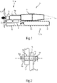
- Fig.1 shows a cross-sectional side view of a propulsion module 1 attached to a wing 2 of an aircraft 3.
- the propulsion module 1 is divided in several parts, namely here a first ("front") part 1a und a second ("rear") part 1b.
- the front part 1a representing the power generating and thrust part, is only attached to the rear part 1b which, in turn, is attached to the wing 2.
- the front part 1a comprises a frame 12 (see Fig.3 to Fig.8 ) surrounded by a fairing 4a to reduce drag penalty.
- Fixed / attached to the frame are an electric motor 5 that drives a propeller 6, an electrochemical converter in form of at least one fuel cell 7, an electric energy storage unit in form of a battery 8, a DC/DC converter 9 for converting the DC voltage / current provided by the fuel cell 7 and/or the battery 8 into voltage / current for operating the electric motor 5, and a cooling system comprising a heat exchanger 10.
- Other components may also be fixed to the frame.
- the aft or rear part 1b which may be placed underneath the wing 2, as shown, hosts a hydrogen storage system comprising a hydrogen tank 11 in a fairing 4b.
- This fairing 4b protects the hydrogen storage system from external damages. It also creates a mechanical link between the wing 2 and the storage system without having to modify the storage system. This is particularly advantageous if an off-the-shelf storage hydrogen tank 11 is used.
- Both parts 1a and 1b are connected via at least one fluid connection line 35 exchanging hydrogen between the second part 1b and the first part 1a and via at least one electric connection line 36, see Fig.14 to Fig.19 below).
- Operation of the propulsion module 1 may comprise at least one out of the group comprising the following four operational phases or states:
- connection / contact area between the first part 1a of the propulsion module 1 and the wing 2 should be as small as possible to reduce the frontal area of the propulsion module 1 and thus the drag penalty.
- notches may be provided in the wing 2 to access the wing spar, which makes attachment easier. This embeds the propulsion module 1 in the wing 2, therefore reducing the frontal connection / contact area.
- a component of the front part 1a (here in one example shown as the battery 8) is attached to the frame 12 by one or more axles 13 that are stuck through congruent through-holes 14 and 15 of the frame 12 and the battery 8, respectively.
- a head 16 of the axle 13 is wider than the hole 14 and thus will not get inserted into hole 14.
- the head 16 may be equipped with a through hole 16a.
- the axle 13 On its other side, outside the hole 15, when having been stuck through both holes 14, 15, the axle 13 comprises a through hole 17 into which a pin or - as shown - an R-clip 18 etc. can be stuck.
- the head 16 on one side and the R-clip 18 on the other side retain the axle 13 in both holes 14, 15. Therefore, the battery 8 is held in position at the frame 12 as long as the axle 13 is not removed.
- such a component like the battery 8 etc. may be held by several axles 13 making sure that it is securely attached to the frame 12.
- Fig.3 shows another possibility to attach the battery 8 to the frame 12 in an analogous view to Fig.2 .
- an axle 19 comprises a ring-shaped notch 20 at its front section, into which a snap ring 21 can be snapped on after insertion of the axle 19 through the holes 14, 15, as indicated by the vertical arrow.
- the snap ring 21, also shown in frontal view, is designed to withstand the loads during normal flight conditions but will fly off at higher loads.
- a component of the propulsion module 1, in particular a component of the front part 1a has degraded or is faulty, it may be advantageous from a safety point of view to move away / separate this faulty component before it may damage other components.
- a degraded condition or an emergency situation regarding such a component e.g., the battery 8
- the present invention proposes the possibility to separate this component from the rest of the propulsion module 1, in particular front part 1a.
- the propulsion module 1 comprises at least one separation means 22 (see Fig.4 to Fig.6 ) adapted to separate this component from the frame 12. The weight of the component then causes it to plunge.
- Separating or detaching one or more components from the rest of the (remaining) propulsion module 1 may also be called “component isolation”, and the respective mechanism a “component isolation mechanism”, in particular, if the separated component is removed out of a fairing.
- component isolation Separating or detaching connection lines or “channels” like fluid connection lines, electric connection lines and/or mechanical connection lines etc.
- the separation of the battery 8 from the frame 12 amounts to a "component isolation".
- the component isolation may be realized by, e.g., the separation means 22 comprising a remotely actuatable actuator and/or a linkage connected to the head 16 by the hole 16a.
- the separation means 22 pulls at the head 16 of the axle 19 in longitudinal axis of the axle 19, as indicated by the pulling load F in Fig.4 .
- the pulling load F is greater than the load experienced under normal conditions.
- the snap ring 21 may first bend (as shown in Fig.5 ) and then fly off the axle 19 (as shown in Fig.6 ) , the R-clip 18 may break or may be deformed so greatly that it can be pulled through the holes 14, 15, etc.
- the axles 13, 19 are then pulled out of the holes 14, 15, thus separating the battery 8 from the frame 12 at this attachment point. When all the attachment points are free, gravity may pull the released battery 8 downward (as shown in Fig.6 ).
- front part 1a It may then fall further out of the front part 1a (e.g., through a hatch). Alternatively or additionally, it may be pushed out of the front part 1a by a mechanical system, e.g., comprising one or more compressed and/or extended springs.
- a mechanical system e.g., comprising one or more compressed and/or extended springs.
- axle(s) 13, 19 may be pushed out of the holes 14, 15 by putting pressure on its free end. Also, the axle(s) 13, 19 may be stuck in the holes 14, 15 in the reverse direction, i.e., the head 16 being positioned at the component to be separated.
- Fig.7 shows a cross-sectional top view of possible shapes of a component of the propulsion module 1 (e.g., the battery 8) and a frame 12 of the propulsion module 1 at their contact area. Also, the holes 14 and 15 are shown.
- the battery 8 comprises two parallel tracks 23 into which respective rails 24 of the frame 12 are inserted.
- the tracks 23 and rails 24 have the same basic shape that widens inside the battery 8.
- the battery 8 can only the moved relative to the frame 12 along the tracks 23 (i.e., along the contact area) but cannot be lifted from the frame 12 (i.e., perpendicular to the contact area).
- the axle 13 or 19 is inserted into the holes 14, 15, it prevents relative movement of the battery 8 along the frame 12.
- This arrangement is particularly advantageous because it prevents forces to be exerted along the axle under normal operating conditions and thus prevents the axle 13 or 19 to be dislodged without actuating the separation means 22.
- the tracks 23 are open at least at the top.
- Fig.8 shows a cross-sectional top view of other possible shapes of a component of the propulsion module 1 (e.g., the battery 8) and a frame 12 of the propulsion module 1 at their contact area.
- the shown arrangement is similar to Fig.7 , with the cross-sectional shape of the tracks 25 and the rails 26 now being trapezoidal.
- tracks 23 and rails 24 as well as the tracks 25 and rails 26 can also be of reversed arrangements, e.g., with the tracks 23 and 25 in the frame 12 and the rails 24 and 26 in the battery 8. In this case, to be able to separate the battery 8 from the frame 12 due to the weight of the battery 8, tracks 23, 25 are open at least at the bottom.
- the tracks 23 and rails 24 and/or the tracks 25 and rails 26 are aligned in an - at least substantially - vertical direction. This gives the advantage that the battery 8 can slide down along the frame 12 by gravitational pull and/or moved by a spring force when the axle(s) 13, 19 are removed.
- Fig.9 shows a cross-sectional side view of the wing 2 and front part 1a of the propulsion module 1 with the battery 8 attached to the frame 12.
- the rear part 1b is not shown.
- the underside of the fairing 4a of the front part 1a comprises a hatch 27 that opens to release the detached / separated battery 8 out of the fairing 4a. Without further measures, the battery 8, when released from the fairing 4a, will freely fall to the ground.
- the battery 8 is tethered to a spool 28 positioned in the front part 1a via a mechanical cable / tether 29. This avoids uncontrolled fall of the battery 8 and potential injury or damage from its free fall.
- one end of the tether 29 is attached to the battery 8 and the other end is attached to the spool 28.
- the tether 29 is wound up on the spool 28.
- the battery 8 is slidably connected to an extendable pole 30.
- the pole 30 gives the advantage that it prevents the battery 8 from hitting the front part 1a, the rear part 1b or the wing 2, since it is adapted to guide the battery 8 during the initial phase of its fall.
- the pole 30 is in a retracted state and therefore so short, that it fits into the fairing 4a.
- Fig.10 shows a cross-sectional side view analogous to Fig.9 with the battery 8 having been separated from the frame (e.g., caused by actuation of the separation means 22) in the initial phase of separation in which the hatch 27 has been opened and the battery 8 slides down the now extended pole 30. While sliding down, the tether 29 unwinds from the spool 28.
- Fig.11 shows cross-sectional side view analogous to Fig.10 in a later phase of the separation in which the battery 8 has slid down the pole 30, has detached from the pole 30 and now hangs by the unwound tether 29 at a safe distance from any structural part of the aircraft 3.
- the spool-attached end of the tether 29 may be released on command, and the battery 8 then drops to the ground in a known drop area.
- the aircraft 3 lands safely without risking tangling the tether 29 in the propellers 6 or the wheels during the deceleration phase.
- the battery 8 and the tether 29 can be retrieved.
- Fig.12 shows an oblique view on a cut-out of a frame 12 of the propulsion module 1 having a hole 31 that is elongated or slotted in the vertical direction.
- This hole 31 can be present in addition to one or more of the holes 14 described above.
- the frame 12 is further equipped with parallel tracks 33, e.g., in form of the tracks 23 or 25 described above, that are shown to be vertically aligned.
- Fig.13 shows an oblique view on a cut-out of a separable component (here: of a battery 8, as an example) of the propulsion module 1 having a hole 32 that is also elongated or slotted in the vertical direction.
- This hole 32 can be present in addition to one or more of the holes 15 described above.
- the battery 8 is further equipped with parallel rails 34, e.g., in form of the tracks 24 or 26 described above, that are shown to be vertically aligned and fit into the tracks 33 of the frame 12. If not held in position by the at least one axle 13 or 19, the battery 8 slides down the frame 12 in the vertical direction along the tracks 33.
- parallel rails 34 e.g., in form of the tracks 24 or 26 described above, that are shown to be vertically aligned and fit into the tracks 33 of the frame 12. If not held in position by the at least one axle 13 or 19, the battery 8 slides down the frame 12 in the vertical direction along the tracks 33.
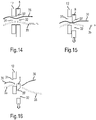
- connection channels / connection lines 35, 36 may be passed / laid one or more connection channels / connection lines 35, 36 (see, e.g., Fig.14 to Fig.16 ) in form of at least one fluid connection line 35 (in form of a tube, for example) and/or at least one electric connection line 36 (a data cable and/or a power cord, for example) and/or at least one mechanical line (a thin metallic wire or a plastic cable, for example).
- connection line(s) 35, 36 When a component of the propulsion module 1, in particular of the front part 1a, is connected to connection lines 35, 36, separation of the component from the frame 12 may not be sufficient to also separate the connection line(s) 35, 36, leading to a failure to fully separate, and/or the separation leads to excessive pulling loads on at least one connection line(s) 35, 36.
- One solution to this problem is to provide the connection line(s) 35 and/or 36 with a mechanically weak connection interface and/or with a predetermined breaking point. This, however, may also negatively affect the stability and reliability under normal operating conditions, in particular, if the connection line is a pressurized fluid connection line 35. To overcome this problem, the following embodiment is proposed that amounts to a disconnecting technique:
Landscapes
- Engineering & Computer Science (AREA)
- Aviation & Aerospace Engineering (AREA)
- Life Sciences & Earth Sciences (AREA)
- Sustainable Development (AREA)
- Sustainable Energy (AREA)
- Chemical & Material Sciences (AREA)
- Power Engineering (AREA)
- Transportation (AREA)
- Mechanical Engineering (AREA)
- Manufacturing & Machinery (AREA)
- Chemical Kinetics & Catalysis (AREA)
- Electrochemistry (AREA)
- General Chemical & Material Sciences (AREA)
- Combustion & Propulsion (AREA)
- Filling Or Discharging Of Gas Storage Vessels (AREA)
- Arrangement Or Mounting Of Propulsion Units For Vehicles (AREA)
- Toys (AREA)
Priority Applications (4)
| Application Number | Priority Date | Filing Date | Title |
|---|---|---|---|
| CN202280011023.5A CN116723979A (zh) | 2021-01-22 | 2022-01-20 | 飞行器推进模块和飞行器 |
| US18/262,252 US12291348B2 (en) | 2021-01-22 | 2022-01-20 | Aircraft propulsion module and aircraft |
| EP22701245.7A EP4281371B1 (de) | 2021-01-22 | 2022-01-20 | Flugzeugantriebsmodul und flugzeug |
| PCT/EP2022/051236 WO2022157245A1 (en) | 2021-01-22 | 2022-01-20 | Aircraft propulsion module and aircraft |
Applications Claiming Priority (1)
| Application Number | Priority Date | Filing Date | Title |
|---|---|---|---|
| EP21153046.4A EP4032810A1 (de) | 2021-01-22 | 2021-01-22 | Flugzeug mit elektrischem antriebsmodul |
Publications (2)
| Publication Number | Publication Date |
|---|---|
| EP4032811A1 true EP4032811A1 (de) | 2022-07-27 |
| EP4032811B1 EP4032811B1 (de) | 2025-03-05 |
Family
ID=74215746
Family Applications (4)
| Application Number | Title | Priority Date | Filing Date |
|---|---|---|---|
| EP21153046.4A Withdrawn EP4032810A1 (de) | 2021-01-22 | 2021-01-22 | Flugzeug mit elektrischem antriebsmodul |
| EP21173058.5A Active EP4032807B1 (de) | 2021-01-22 | 2021-05-10 | Flugzeug mit einziehbaren wirbelgeneratoren |
| EP21186951.6A Active EP4032811B1 (de) | 2021-01-22 | 2021-07-21 | Flugzeugantriebsmodul und flugzeug |
| EP22701243.2A Active EP4281370B1 (de) | 2021-01-22 | 2022-01-20 | Flugzeug mit elektrischem antriebsmodul |
Family Applications Before (2)
| Application Number | Title | Priority Date | Filing Date |
|---|---|---|---|
| EP21153046.4A Withdrawn EP4032810A1 (de) | 2021-01-22 | 2021-01-22 | Flugzeug mit elektrischem antriebsmodul |
| EP21173058.5A Active EP4032807B1 (de) | 2021-01-22 | 2021-05-10 | Flugzeug mit einziehbaren wirbelgeneratoren |
Family Applications After (1)
| Application Number | Title | Priority Date | Filing Date |
|---|---|---|---|
| EP22701243.2A Active EP4281370B1 (de) | 2021-01-22 | 2022-01-20 | Flugzeug mit elektrischem antriebsmodul |
Country Status (4)
| Country | Link |
|---|---|
| US (1) | US20240308674A1 (de) |
| EP (4) | EP4032810A1 (de) |
| CN (1) | CN116867708A (de) |
| WO (1) | WO2022157241A1 (de) |
Cited By (1)
| Publication number | Priority date | Publication date | Assignee | Title |
|---|---|---|---|---|
| WO2024089670A1 (en) | 2022-10-28 | 2024-05-02 | H3 Dynamics Holdings Pte. Ltd. | Frame device for a propulsion unit of a flight device |
Families Citing this family (4)
| Publication number | Priority date | Publication date | Assignee | Title |
|---|---|---|---|---|
| WO2020060488A1 (en) * | 2018-09-18 | 2020-03-26 | H3 Dynamics Holdings Pte. Ltd. | Unmanned vehicle |
| US11577846B2 (en) * | 2020-02-21 | 2023-02-14 | ZeroAvia, Inc. | Modular electric powertrain conversion for aircraft |
| WO2022245427A2 (en) * | 2021-03-31 | 2022-11-24 | Zeroavia Ltd. | Refueling system for hydrogen fuel cell-powered aircraft |
| CN116834959B (zh) * | 2022-08-10 | 2025-09-26 | 北京纳米能源与系统研究所 | 运动体失速自驱动预警单元、预警方法和辅助设计方法 |
Citations (6)
| Publication number | Priority date | Publication date | Assignee | Title |
|---|---|---|---|---|
| US20080261084A1 (en) * | 2007-04-20 | 2008-10-23 | Honeywell International Inc. | Fuel cells used to supplement power sources for aircraft equipment |
| DE202016006522U1 (de) * | 2016-10-21 | 2016-12-01 | Askan Simon | Elektrische Aufstiegshilfe für Gleitschirme |
| WO2019241581A1 (en) * | 2018-06-16 | 2019-12-19 | Marinus Bernard Bosma | Electrically-powered aircraft with pod-mounted batteries |
| WO2020003181A1 (en) | 2018-06-27 | 2020-01-02 | H3 Dynamics Holdings Pte. Ltd. | Distributed electric energy pods network and associated electrically powered vehicle |
| WO2020060488A1 (en) * | 2018-09-18 | 2020-03-26 | H3 Dynamics Holdings Pte. Ltd. | Unmanned vehicle |
| FR3097201A1 (fr) * | 2019-06-14 | 2020-12-18 | Airbus | Aeronef comportant une pluralite de systemes autonomes de propulsion a helice avec une pile a combustible |
Family Cites Families (20)
| Publication number | Priority date | Publication date | Assignee | Title |
|---|---|---|---|---|
| GB1070723A (en) | 1963-01-16 | 1967-06-01 | Dehavilland Aircraft | Improvements in or relating to aircraft |
| US3777420A (en) * | 1972-08-04 | 1973-12-11 | Mattel Inc | Detachable power module for flying toy aircraft |
| US3960345A (en) * | 1975-05-16 | 1976-06-01 | Grumman Aerospace Corporation | Means to reduce and/or eliminate vortices, caused by wing body combinations |
| US4039161A (en) | 1975-10-16 | 1977-08-02 | Mcdonnell Douglas Corporation | Hidden vortex generators |
| US5106035A (en) * | 1989-12-29 | 1992-04-21 | Aurora Flight Sciences Corporation | Aircraft propulsion system using air liquefaction and storage |
| US5253828A (en) | 1992-07-17 | 1993-10-19 | The Board Of Regents Of The University Of Oklahoma | Concealable flap-actuated vortex generator |
| US6837465B2 (en) * | 2003-01-03 | 2005-01-04 | Orbital Research Inc | Flow control device and method of controlling flow |
| US6685143B1 (en) * | 2003-01-03 | 2004-02-03 | Orbital Research Inc. | Aircraft and missile forebody flow control device and method of controlling flow |
| BRPI0613492A2 (pt) | 2005-06-30 | 2011-01-11 | Bell Helicopter Textron Inc | gerador de vórtice retrátil |
| US8087617B2 (en) * | 2008-08-15 | 2012-01-03 | The Boeing Company | Retractable nacelle chine |
| US8657238B2 (en) | 2011-07-05 | 2014-02-25 | The Boeing Company | Retractable vortex generator for reducing stall speed |
| US9505485B2 (en) | 2012-05-08 | 2016-11-29 | Lockheed Martin Corporation | Vortex generation |
| FR3002594B1 (fr) * | 2013-02-26 | 2016-09-30 | Snecma | Module de propulsion spatiale a propulsion electrique et chimique a propergol solide |
| DE102015101765A1 (de) | 2015-02-06 | 2016-08-11 | Airbus Operations Gmbh | Vortexgeneratoranordnung |
| GB2538982A (en) * | 2015-05-30 | 2016-12-07 | Victor Sills Nicholas | Self-contained, electric contra rotating propeller propulsion apparatus for aircraft |
| DE102015120958A1 (de) * | 2015-12-02 | 2017-06-08 | Dg Flugzeugbau Gmbh | Aktives Positionieren von Turbulatorflächenelementen |
| US10752343B2 (en) * | 2016-10-18 | 2020-08-25 | Sikorsky Aircraft Corporation | Electric propulsion system for a rotary wing aircraft |
| ES2991416T3 (es) * | 2019-06-12 | 2024-12-03 | Airbus Operations Slu | Generador de vórtices de cuchilla |
| FR3097202B1 (fr) * | 2019-06-14 | 2024-02-23 | Airbus | Systeme autonome de propulsion a helice pour un aeronef, ledit systeme autonome de propulsion a helice comportant une pile a combustible |
| DE202020005286U1 (de) * | 2020-12-22 | 2021-02-10 | Christian Sturm | Integrierte Flugantriebseinheit |
-
2021
- 2021-01-22 EP EP21153046.4A patent/EP4032810A1/de not_active Withdrawn
- 2021-05-10 EP EP21173058.5A patent/EP4032807B1/de active Active
- 2021-07-21 EP EP21186951.6A patent/EP4032811B1/de active Active
-
2022
- 2022-01-20 WO PCT/EP2022/051227 patent/WO2022157241A1/en not_active Ceased
- 2022-01-20 US US18/262,257 patent/US20240308674A1/en active Pending
- 2022-01-20 CN CN202280011030.5A patent/CN116867708A/zh active Pending
- 2022-01-20 EP EP22701243.2A patent/EP4281370B1/de active Active
Patent Citations (6)
| Publication number | Priority date | Publication date | Assignee | Title |
|---|---|---|---|---|
| US20080261084A1 (en) * | 2007-04-20 | 2008-10-23 | Honeywell International Inc. | Fuel cells used to supplement power sources for aircraft equipment |
| DE202016006522U1 (de) * | 2016-10-21 | 2016-12-01 | Askan Simon | Elektrische Aufstiegshilfe für Gleitschirme |
| WO2019241581A1 (en) * | 2018-06-16 | 2019-12-19 | Marinus Bernard Bosma | Electrically-powered aircraft with pod-mounted batteries |
| WO2020003181A1 (en) | 2018-06-27 | 2020-01-02 | H3 Dynamics Holdings Pte. Ltd. | Distributed electric energy pods network and associated electrically powered vehicle |
| WO2020060488A1 (en) * | 2018-09-18 | 2020-03-26 | H3 Dynamics Holdings Pte. Ltd. | Unmanned vehicle |
| FR3097201A1 (fr) * | 2019-06-14 | 2020-12-18 | Airbus | Aeronef comportant une pluralite de systemes autonomes de propulsion a helice avec une pile a combustible |
Cited By (1)
| Publication number | Priority date | Publication date | Assignee | Title |
|---|---|---|---|---|
| WO2024089670A1 (en) | 2022-10-28 | 2024-05-02 | H3 Dynamics Holdings Pte. Ltd. | Frame device for a propulsion unit of a flight device |
Also Published As
| Publication number | Publication date |
|---|---|
| CN116867708A (zh) | 2023-10-10 |
| EP4032807B1 (de) | 2025-02-26 |
| EP4032807A1 (de) | 2022-07-27 |
| EP4032811B1 (de) | 2025-03-05 |
| EP4281370B1 (de) | 2024-10-23 |
| WO2022157241A1 (en) | 2022-07-28 |
| EP4281370A1 (de) | 2023-11-29 |
| EP4032810A1 (de) | 2022-07-27 |
| US20240308674A1 (en) | 2024-09-19 |
Similar Documents
| Publication | Publication Date | Title |
|---|---|---|
| EP4032811B1 (de) | Flugzeugantriebsmodul und flugzeug | |
| EP4281371B1 (de) | Flugzeugantriebsmodul und flugzeug | |
| US9650138B2 (en) | Long range electric aircraft and method of operating same | |
| US9815563B2 (en) | Long range electric aircraft and method of operating same | |
| Robbins et al. | F-35 subsystems design, development & verification | |
| EP4091868A1 (de) | Hybrid-elektrische und vollelektrische flugzeugantriebssysteme | |
| KR102771357B1 (ko) | 수소 연료전지 항공체 | |
| CN116723979A (zh) | 飞行器推进模块和飞行器 | |
| DE102020002267B4 (de) | Carrierdrohne oder Schleppdrohne | |
| US20220388668A1 (en) | Aircraft Safety Livesaving System | |
| CN213566511U (zh) | 一种无人机保护装置 | |
| US20220388669A1 (en) | Aircraft Safety Livesaving System | |
| EP4691911A1 (de) | Flugzeugservicesystem auf dem boden | |
| US20240400227A1 (en) | On-ground aircraft service system | |
| WO2016085337A1 (en) | Wind power generation system and method of operating the same | |
| CN205311912U (zh) | 一种航空电动绞车吊舱 | |
| EP4395117A1 (de) | Elektrisches ladesystem während des fluges und verfahren für ein batteriebetriebenes flugzeug | |
| RU2277060C1 (ru) | Самолет | |
| CN113955125B (zh) | 飞机安全救生系统 | |
| Fernandez-Garcia et al. | Autonomous Electrical Power System for Multi Role Transport Tanker Aircraft | |
| EP4608722A1 (de) | Rahmenvorrichtung für eine antriebseinheit einer flugvorrichtung |
Legal Events
| Date | Code | Title | Description |
|---|---|---|---|
| PUAI | Public reference made under article 153(3) epc to a published international application that has entered the european phase |
Free format text: ORIGINAL CODE: 0009012 |
|
| STAA | Information on the status of an ep patent application or granted ep patent |
Free format text: STATUS: THE APPLICATION HAS BEEN PUBLISHED |
|
| AK | Designated contracting states |
Kind code of ref document: A1 Designated state(s): AL AT BE BG CH CY CZ DE DK EE ES FI FR GB GR HR HU IE IS IT LI LT LU LV MC MK MT NL NO PL PT RO RS SE SI SK SM TR |
|
| STAA | Information on the status of an ep patent application or granted ep patent |
Free format text: STATUS: REQUEST FOR EXAMINATION WAS MADE |
|
| 17P | Request for examination filed |
Effective date: 20230126 |
|
| RBV | Designated contracting states (corrected) |
Designated state(s): AL AT BE BG CH CY CZ DE DK EE ES FI FR GB GR HR HU IE IS IT LI LT LU LV MC MK MT NL NO PL PT RO RS SE SI SK SM TR |
|
| STAA | Information on the status of an ep patent application or granted ep patent |
Free format text: STATUS: EXAMINATION IS IN PROGRESS |
|
| 17Q | First examination report despatched |
Effective date: 20231204 |
|
| GRAP | Despatch of communication of intention to grant a patent |
Free format text: ORIGINAL CODE: EPIDOSNIGR1 |
|
| STAA | Information on the status of an ep patent application or granted ep patent |
Free format text: STATUS: GRANT OF PATENT IS INTENDED |
|
| INTG | Intention to grant announced |
Effective date: 20241008 |
|
| GRAS | Grant fee paid |
Free format text: ORIGINAL CODE: EPIDOSNIGR3 |
|
| GRAA | (expected) grant |
Free format text: ORIGINAL CODE: 0009210 |
|
| STAA | Information on the status of an ep patent application or granted ep patent |
Free format text: STATUS: THE PATENT HAS BEEN GRANTED |
|
| AK | Designated contracting states |
Kind code of ref document: B1 Designated state(s): AL AT BE BG CH CY CZ DE DK EE ES FI FR GB GR HR HU IE IS IT LI LT LU LV MC MK MT NL NO PL PT RO RS SE SI SK SM TR |
|
| REG | Reference to a national code |
Ref country code: GB Ref legal event code: FG4D |
|
| REG | Reference to a national code |
Ref country code: CH Ref legal event code: EP |
|
| REG | Reference to a national code |
Ref country code: IE Ref legal event code: FG4D |
|
| REG | Reference to a national code |
Ref country code: DE Ref legal event code: R096 Ref document number: 602021027038 Country of ref document: DE |
|
| PG25 | Lapsed in a contracting state [announced via postgrant information from national office to epo] |
Ref country code: RS Free format text: LAPSE BECAUSE OF FAILURE TO SUBMIT A TRANSLATION OF THE DESCRIPTION OR TO PAY THE FEE WITHIN THE PRESCRIBED TIME-LIMIT Effective date: 20250605 |
|
| PG25 | Lapsed in a contracting state [announced via postgrant information from national office to epo] |
Ref country code: FI Free format text: LAPSE BECAUSE OF FAILURE TO SUBMIT A TRANSLATION OF THE DESCRIPTION OR TO PAY THE FEE WITHIN THE PRESCRIBED TIME-LIMIT Effective date: 20250305 |
|
| REG | Reference to a national code |
Ref country code: NL Ref legal event code: MP Effective date: 20250305 |
|
| PG25 | Lapsed in a contracting state [announced via postgrant information from national office to epo] |
Ref country code: ES Free format text: LAPSE BECAUSE OF FAILURE TO SUBMIT A TRANSLATION OF THE DESCRIPTION OR TO PAY THE FEE WITHIN THE PRESCRIBED TIME-LIMIT Effective date: 20250305 |
|
| REG | Reference to a national code |
Ref country code: LT Ref legal event code: MG9D |
|
| PG25 | Lapsed in a contracting state [announced via postgrant information from national office to epo] |
Ref country code: NO Free format text: LAPSE BECAUSE OF FAILURE TO SUBMIT A TRANSLATION OF THE DESCRIPTION OR TO PAY THE FEE WITHIN THE PRESCRIBED TIME-LIMIT Effective date: 20250605 |
|
| PG25 | Lapsed in a contracting state [announced via postgrant information from national office to epo] |
Ref country code: HR Free format text: LAPSE BECAUSE OF FAILURE TO SUBMIT A TRANSLATION OF THE DESCRIPTION OR TO PAY THE FEE WITHIN THE PRESCRIBED TIME-LIMIT Effective date: 20250305 |
|
| PG25 | Lapsed in a contracting state [announced via postgrant information from national office to epo] |
Ref country code: LV Free format text: LAPSE BECAUSE OF FAILURE TO SUBMIT A TRANSLATION OF THE DESCRIPTION OR TO PAY THE FEE WITHIN THE PRESCRIBED TIME-LIMIT Effective date: 20250305 |
|
| PG25 | Lapsed in a contracting state [announced via postgrant information from national office to epo] |
Ref country code: BG Free format text: LAPSE BECAUSE OF FAILURE TO SUBMIT A TRANSLATION OF THE DESCRIPTION OR TO PAY THE FEE WITHIN THE PRESCRIBED TIME-LIMIT Effective date: 20250305 Ref country code: GR Free format text: LAPSE BECAUSE OF FAILURE TO SUBMIT A TRANSLATION OF THE DESCRIPTION OR TO PAY THE FEE WITHIN THE PRESCRIBED TIME-LIMIT Effective date: 20250606 |
|
| REG | Reference to a national code |
Ref country code: AT Ref legal event code: MK05 Ref document number: 1772765 Country of ref document: AT Kind code of ref document: T Effective date: 20250305 |
|
| PG25 | Lapsed in a contracting state [announced via postgrant information from national office to epo] |
Ref country code: NL Free format text: LAPSE BECAUSE OF FAILURE TO SUBMIT A TRANSLATION OF THE DESCRIPTION OR TO PAY THE FEE WITHIN THE PRESCRIBED TIME-LIMIT Effective date: 20250305 |
|
| PG25 | Lapsed in a contracting state [announced via postgrant information from national office to epo] |
Ref country code: SE Free format text: LAPSE BECAUSE OF FAILURE TO SUBMIT A TRANSLATION OF THE DESCRIPTION OR TO PAY THE FEE WITHIN THE PRESCRIBED TIME-LIMIT Effective date: 20250305 |
|
| P01 | Opt-out of the competence of the unified patent court (upc) registered |
Free format text: CASE NUMBER: UPC_APP_4142_4032811/2025 Effective date: 20250825 |
|
| PG25 | Lapsed in a contracting state [announced via postgrant information from national office to epo] |
Ref country code: SM Free format text: LAPSE BECAUSE OF FAILURE TO SUBMIT A TRANSLATION OF THE DESCRIPTION OR TO PAY THE FEE WITHIN THE PRESCRIBED TIME-LIMIT Effective date: 20250305 |
|
| PG25 | Lapsed in a contracting state [announced via postgrant information from national office to epo] |
Ref country code: PT Free format text: LAPSE BECAUSE OF FAILURE TO SUBMIT A TRANSLATION OF THE DESCRIPTION OR TO PAY THE FEE WITHIN THE PRESCRIBED TIME-LIMIT Effective date: 20250707 |
|
| PGFP | Annual fee paid to national office [announced via postgrant information from national office to epo] |
Ref country code: DE Payment date: 20250804 Year of fee payment: 5 |
|
| REG | Reference to a national code |
Ref country code: DE Ref legal event code: R082 Ref document number: 602021027038 Country of ref document: DE Representative=s name: SCHULZE, MARK, DIPL.-PHYS. DR.RER.NAT., DE |
|
| PG25 | Lapsed in a contracting state [announced via postgrant information from national office to epo] |
Ref country code: IT Free format text: LAPSE BECAUSE OF FAILURE TO SUBMIT A TRANSLATION OF THE DESCRIPTION OR TO PAY THE FEE WITHIN THE PRESCRIBED TIME-LIMIT Effective date: 20250305 Ref country code: PL Free format text: LAPSE BECAUSE OF FAILURE TO SUBMIT A TRANSLATION OF THE DESCRIPTION OR TO PAY THE FEE WITHIN THE PRESCRIBED TIME-LIMIT Effective date: 20250305 |
|
| PGFP | Annual fee paid to national office [announced via postgrant information from national office to epo] |
Ref country code: GB Payment date: 20250722 Year of fee payment: 5 |
|
| PG25 | Lapsed in a contracting state [announced via postgrant information from national office to epo] |
Ref country code: AT Free format text: LAPSE BECAUSE OF FAILURE TO SUBMIT A TRANSLATION OF THE DESCRIPTION OR TO PAY THE FEE WITHIN THE PRESCRIBED TIME-LIMIT Effective date: 20250305 |
|
| PGFP | Annual fee paid to national office [announced via postgrant information from national office to epo] |
Ref country code: FR Payment date: 20250723 Year of fee payment: 5 |
|
| PG25 | Lapsed in a contracting state [announced via postgrant information from national office to epo] |
Ref country code: CZ Free format text: LAPSE BECAUSE OF FAILURE TO SUBMIT A TRANSLATION OF THE DESCRIPTION OR TO PAY THE FEE WITHIN THE PRESCRIBED TIME-LIMIT Effective date: 20250305 Ref country code: EE Free format text: LAPSE BECAUSE OF FAILURE TO SUBMIT A TRANSLATION OF THE DESCRIPTION OR TO PAY THE FEE WITHIN THE PRESCRIBED TIME-LIMIT Effective date: 20250305 |
|
| PG25 | Lapsed in a contracting state [announced via postgrant information from national office to epo] |
Ref country code: RO Free format text: LAPSE BECAUSE OF FAILURE TO SUBMIT A TRANSLATION OF THE DESCRIPTION OR TO PAY THE FEE WITHIN THE PRESCRIBED TIME-LIMIT Effective date: 20250305 |
|
| PG25 | Lapsed in a contracting state [announced via postgrant information from national office to epo] |
Ref country code: SK Free format text: LAPSE BECAUSE OF FAILURE TO SUBMIT A TRANSLATION OF THE DESCRIPTION OR TO PAY THE FEE WITHIN THE PRESCRIBED TIME-LIMIT Effective date: 20250305 |
|
| PG25 | Lapsed in a contracting state [announced via postgrant information from national office to epo] |
Ref country code: IS Free format text: LAPSE BECAUSE OF FAILURE TO SUBMIT A TRANSLATION OF THE DESCRIPTION OR TO PAY THE FEE WITHIN THE PRESCRIBED TIME-LIMIT Effective date: 20250705 |
|
| REG | Reference to a national code |
Ref country code: DE Ref legal event code: R097 Ref document number: 602021027038 Country of ref document: DE |
|
| PLBE | No opposition filed within time limit |
Free format text: ORIGINAL CODE: 0009261 |
|
| STAA | Information on the status of an ep patent application or granted ep patent |
Free format text: STATUS: NO OPPOSITION FILED WITHIN TIME LIMIT |
|
| PG25 | Lapsed in a contracting state [announced via postgrant information from national office to epo] |
Ref country code: DK Free format text: LAPSE BECAUSE OF FAILURE TO SUBMIT A TRANSLATION OF THE DESCRIPTION OR TO PAY THE FEE WITHIN THE PRESCRIBED TIME-LIMIT Effective date: 20250305 |
|
| REG | Reference to a national code |
Ref country code: CH Ref legal event code: L10 Free format text: ST27 STATUS EVENT CODE: U-0-0-L10-L00 (AS PROVIDED BY THE NATIONAL OFFICE) Effective date: 20260114 |
|
| 26N | No opposition filed |
Effective date: 20251208 |
|
| REG | Reference to a national code |
Ref country code: CH Ref legal event code: H13 Free format text: ST27 STATUS EVENT CODE: U-0-0-H10-H13 (AS PROVIDED BY THE NATIONAL OFFICE) Effective date: 20260224 |
|
| PG25 | Lapsed in a contracting state [announced via postgrant information from national office to epo] |
Ref country code: LU Free format text: LAPSE BECAUSE OF NON-PAYMENT OF DUE FEES Effective date: 20250721 |
|
| REG | Reference to a national code |
Ref country code: BE Ref legal event code: MM Effective date: 20250731 |
|
| PG25 | Lapsed in a contracting state [announced via postgrant information from national office to epo] |
Ref country code: BE Free format text: LAPSE BECAUSE OF NON-PAYMENT OF DUE FEES Effective date: 20250731 |