EP4279686B1 - Stopfen zum verschliessen von löchern in betonwänden - Google Patents
Stopfen zum verschliessen von löchern in betonwänden Download PDFInfo
- Publication number
- EP4279686B1 EP4279686B1 EP22382469.9A EP22382469A EP4279686B1 EP 4279686 B1 EP4279686 B1 EP 4279686B1 EP 22382469 A EP22382469 A EP 22382469A EP 4279686 B1 EP4279686 B1 EP 4279686B1
- Authority
- EP
- European Patent Office
- Prior art keywords
- plug
- main body
- retention
- hole
- concrete wall
- Prior art date
- Legal status (The legal status is an assumption and is not a legal conclusion. Google has not performed a legal analysis and makes no representation as to the accuracy of the status listed.)
- Active
Links
Images






Classifications
-
- E—FIXED CONSTRUCTIONS
- E04—BUILDING
- E04G—SCAFFOLDING; FORMS; SHUTTERING; BUILDING IMPLEMENTS OR AIDS, OR THEIR USE; HANDLING BUILDING MATERIALS ON THE SITE; REPAIRING, BREAKING-UP OR OTHER WORK ON EXISTING BUILDINGS
- E04G17/00—Connecting or other auxiliary members for forms, falsework structures, or shutterings
- E04G17/06—Tying means; Spacers ; Devices for extracting or inserting wall ties
- E04G17/0644—Plug means for tie-holes
Definitions
- the present invention relates to closing plugs for covering and concealing holes in concrete walls, said holes preferably being made by the formwork anchoring system.
- Closing plugs for covering and concealing holes in concrete walls and the like are known. Said holes are usually made by the manufacturing process of said concrete walls.
- Concrete walls are manufactured on site, providing a gap between two formwork panels that are arranged in such a way that they face each other. These panels are secured together by means of an anchoring system comprising transverse bolts the ends of which are threaded. Said threaded ends protrude from the formwork panels so that the corresponding nuts can be threaded, thus securing the formwork panels.
- DE202006005621U1 describes a decorative plug for concealing a hole in a concrete wall, which hole is generated by the manufacturing process of said wall.
- Said plug comprises a main body made of plastic and elastic retention means, also made of plastic, which retain the plug in place inside the protective plastic tube of the hole in the concrete wall.
- the plug comprises a frustoconical head and a cylindrical appendage extending from said head.
- a decorative metallic disc is fixed at the end of the head by means of adhesive.
- the elastic means comprise in one embodiment a plurality of elongated ribs arranged on the appendage such that they radially protrude.
- DE202008015694 U1 describes a plug for closing a hole in a concrete wall, comprising a main body and conically tapering retention means.
- the retention means comprise a sleeve shaped body, which is partially embedded in the main body, and three encircling hooks projecting from the sleeve shaped body, the plug being retained inside the hole by the hooks.
- the object of the invention is to provide a plug according to claim 1.
- the plug of the invention comprises a main body and elastic retention means, said retention means being partially embedded in the main body.
- the retention means also comprise at least one set of two hooks arranged diametrically opposite to one another and at least partially projecting from the main body, said hooks being configured for cooperating with the hole of the concrete wall for retaining the plug in said hole.
- Each hook comprises a respective retention flange, the free end of the flange being at a distance from a longitudinal axis of the plug, said distance being greater than the radius of the hole of the concrete wall to be plugged, such that, in use, with the plug being arranged inside the hole to be plugged, the flange is compressed inside the hole.
- the two retention flanges are attached to one another by a U-shaped retention element, part of said retention element being embedded in the main body.
- the plug of the invention is facilitated with the plug of the invention because it is not necessary to use additional means, such as adhesives, for example, to retain the plug in place. Furthermore, the securing of said plug is also improved because the hook of the elastic means provides good securing whether the hole to be plugged comprises the protective plastic tube of the transverse bolts (securing on a plastic material) or does not comprise said tube (securing directly on the concrete).
- FIGS 1A and 1B show a first embodiment of the plug 1 according to the invention.
- the plug 1 of the invention comprises a main body 2 and elastic retention means 4, the retention means 4 being partially embedded in the main body 2.
- the retention means 4 comprise at least one hook at least partially projecting from the main body 2 and configured for cooperating with the hole 8 in the concrete wall 9 for retaining the plug 1 in place inside said hole 8.
- the retention means 4 can also comprise a plurality of hooks protruding at least partially from the main body 2.
- the retention means 4 comprise four hooks arranged as will be described in detail below.
- the plug 1 in use i.e., when the plug 1 is introduced in the hole 8 to be plugged, is aligned with the wall or concrete wall 9, thereby concealing said hole 8, as can be seen in Figure 11B for example.
- Holes in concrete walls are unavoidable because most, if not all of said holes, are caused by the manufacturing process of the concrete wall 9 itself.
- the plug 1 of the invention provides an easy placement of the plug 1 in the hole 8 in the concrete wall 9 to be plugged because it is not necessary to use additional means, such as adhesives, for example, for retaining the plug 1 in place. Furthermore, the securing of said plug 1 is also improved because the hook or hooks of the elastic means 4 provide very good securing whether the hole 8 to be plugged comprises the protective plastic tube of the transverse bolts (securing on plastic material) or does not comprise said tube no (securing directly on concrete).
- the retention means 4 comprise a plurality of hooks, preferably four, each hook comprising a retention flange 4a forming an acute angle ⁇ with respect to a longitudinal axis X of the plug 1, as can be seen in Figure 1B , or in greater detail in Figure 2B , each retention flange 4a extending in a direction opposite an insertion direction A one of the plug 1, wherein the plug 1 is brought closer to the hole 8 to be plugged.
- the plug 1 of the invention is easily arranged in place because no great effort is required to insert the plug 1 inside the hole 8 to be plugged, but at the same time the flanges 4a provide good securing which lasts over time such that additional means, such as adhesive, for example, are not necessary to keep the plug of the invention in place.
- the free ends of the flanges 4a of the retention means 4 are arranged at a distance d from the longitudinal axis X of the plug 1, said distance d being greater than the radius of the hole 8 in the concrete wall 9 to be plugged, such that, in use, with the plug 1 being arranged inside the hole 8 to be plugged, and preferably aligned with the concrete wall 9, the flanges 4a are compressed inside the hole 8, as can be seen in Figure 11B , the free ends of the flanges 4a in this case being at a compressed distance d' from the longitudinal axis X of the plug 1, said compressed distance d' being less than the initial distance d.
- the retention flanges 4a are compressed upon entering the hole 8 to be plugged, with the securing force of the plug 1, which force is exerted by the flanges 4a against the surface of the hole 8 to be plugged, being thereby increased.
- the hooks of the retention means 4 independently of the inner surface of the hole 8 to be plugged, exert very good gripping pressure; therefore, independently of whether the hole 8 to be plugged comprises the protective plastic tube of the transverse bolts, necessary in the manufacturing process of the concrete wall 9, or does not comprise said tube, the flanges 4a of the hooks of the retention means 4 adapt to the surface of the hole 8 to be plugged, the plug 1 of the invention being strongly secured inside the hole 8 to be plugged, regardless of the texture of the surface of said hole 8, of plastic (in the event that the hole comprise the plastic protective tube of the transverse bolt), or of concrete (in the event that it does not comprise said plastic protective tube).
- the hole 8 to be plugged does not comprise the protective plastic tube; therefore, the hooks of the retention means 4, i.e., the flanges 4a, apply pressure directly on the concrete.
- the retention means 4 of the plug 1 of the invention comprise a plurality of hooks, these hooks are arranged equidistantly around the longitudinal axis X of the plug 1.
- the retention means 4 comprise at least one set of two retention flanges 4a arranged diametrically opposite to one another, the two retention flanges 4a being attached to one another by a U-shaped retention element 5, as can be seen in Figures 2A and 2B . That is, at each end of the U-shaped retention element 5 there is arranged a corresponding retention flange 4a, correct securing of the plug 1 inside the hole 8 to be plugged thus being assured.
- the retention means 4 comprise two sets of two retention flanges 4a, both sets being arranged rotated with respect to each other, preferably 90°.
- the retention element 5 of each set comprises a base 5a and two legs 5b, each one attached to a corresponding end of said base 5a, as can be seen in Figure 2B , forming a single part.
- the legs 5b and the base 5a are attached perpendicularly, said legs 5b being arranged in this case parallel with the longitudinal axis X of the plug 1.
- the legs 5b can form another different angle with the base 5a, in which case the flanges 4a would continue to form the acute angle ⁇ with respect to the longitudinal axis X of the plug 1.
- the retention flanges 4a can form an acute angle ⁇ with respect to the longitudinal axis X of the plug, or they can be perpendicular to said longitudinal axis X, as will be described in detail below.
- the main body 2 comprises a frustoconical or cylindrical head 6, the main body 2 comprising an active surface 6a, arranged at one end of the head 6, which in use is aligned with the uncovered face 9a of the wall or concrete wall 9, thus concealing the corresponding hole 8.
- the uncovered face 9a refers to the visible surface of the concrete wall 9.
- Said active surface 6a is preferably perpendicular to the longitudinal axis X of the plug 1.
- the main body 2 also comprises an auxiliary surface 6b which in use is arranged inside the hole 8 in the concrete wall 9, the retention means 4 protruding from said auxiliary surface 6b.
- the auxiliary surface 6b is facing the active surface 6a, the retention means 4 protruding axially from the main body 2, i.e., from said auxiliary surface 6b, in the insertion direction A, as shown in Figure 1A .
- the auxiliary surface 6b is the generatrix of the frustoconical or conical head 6, the retention means 4 protruding radially from the main body 2, i.e., perpendicular to the longitudinal axis X, as will be described in detail below.
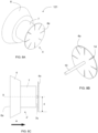
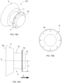
- the shape of the head 6 in the example of Figure 1A is cylindrical, whereas in the examples of Figures 1C and 1E it is frustoconical.
- the main body 2' also comprises, in addition to the frustoconical or cylindrical head 6, a cylindrical appendage 7 having a smaller diameter than the smallest diameter of the head 6, said appendage 7 extending from the head 6 in the insertion direction A, as can be seen in Figure 3B , for example.
- the active surface 6a of the main body 2' which in use is aligned with the uncovered face 9a of the concrete wall 9, is also arranged at one end of the head 6, but the auxiliary surface 7b or 7b' of the main body 2' is arranged in the appendage 7.
- the active surface 6a is also preferably perpendicular to the longitudinal axis X of the plug 1', and the retention means 4, particularly the retention flanges 4a, also protrude from the auxiliary surface 7b or 7b', said auxiliary surface 7b or 7b' also being arranged in use inside the hole 8 in the concrete wall 9.
- the auxiliary surface 7b of the main body 2' of the plug 100 is one of the bases of the cylindrical body forming the appendage 7, i.e., the base arranged at the free end of said appendage 7, such that said auxiliary surface 7b is facing the active surface 6a of the head 6, the retention means 4, particularly the flanges 4a, protruding axially from the appendage 7 in the insertion direction A, as can be seen in Figures 3A and 3B .
- the auxiliary surface 7b' of the main body 2' of the plug 101 is the lateral surface or generatrix of the cylindrical body forming the appendage 7, the retention means 4 protruding radially from the appendage 7, i.e., perpendicular to the longitudinal axis X, as shown in Figures 4A and 4B .
- the retention flanges 4a can form an acute angle ⁇ with respect to the longitudinal axis X of the plug of the invention, and the retention means 4 can also comprise at least one set of two retention flanges 4a arranged diametrically opposite to one another and attached to one another by the U-shaped retention element 5, preferably comprising two sets of two retention flanges 4a, both sets being arranged rotated with respect to each other, preferably 90°.
- the protective kit of the transverse bolt of the manufacturing process of a concrete wall can comprise a central cylindrical segment (cylindrical protective tube made of plastic) to which there is added at each end a frustoconical element made of plastic which is removed once the concrete is set.
- the hole 8 generated in the concrete wall 9 will therefore have two frustoconical openings 8' (made of concrete) arranged at the ends of the hole 8 between which there is arranged a cylindrical segment 8" (made of plastic if the protective tube has not been removed, or made of concrete if said protective tube has been removed), as can be seen in Figure 11A .
- a cylindrical segment 8" made of plastic if the protective tube has not been removed, or made of concrete if said protective tube has been removed
- FIGS 11A and 11B depict a hole 8 with a frustoconical opening 8' (the second opening being omitted) to better understand the invention.
- a frustoconical opening 8' of the hole 8 to be plugged it will be appropriate to use one plug (without an appendage 7) or the other (with the appendage 7) to assure better securing of the plug.
- the plugs 100 or 101 comprising the main body 2' with the appendage 7 (according to any of its variants).
- the plug 1 comprising the main body 2 without the appendage 7 and plugs 100 or 101which do comprise the appendage 7, could be used.
- the head 6 can be adjusted to the shape of the frustoconical opening 8' of the hole 8 such that when said head 6 abuts with the bottom of the frustoconical opening 8', the active surface 6a of the head is aligned with the exposed face 9a of the concrete wall 9.
- the head 6 and said appendage 7 form a single part.
- FIGS 5A and 5B show another embodiment of the plug 110, not being part of the invention, in which the only thing that changes with respect to the described plugs are the elastic retention means 4.
- the main body 2' comprises both the head 6 and the appendage 7 and the retention means 4 comprise a single hook comprising a single conical-shaped retention flange 4a, as can be seen for example in Figure 5C .
- Said retention flange 4a is attached to a mast 10 arranged on its geometric axis, part of said mast 10 being embedded in the main body 2', such that said mast 10 is arranged parallel to or aligned with the longitudinal axis X, the retention means 4 protruding axially from the main body 2' in the insertion direction A.
- FIG. 7A, 7B and 7C differs from the plug 110 described above in the shape of the retention means 4.
- the retention means 4 of this variant also comprise a single hook with a single retention flange 4a, but it is circular in this case.
- the retention flange 4 can be arranged perpendicular to the longitudinal axis X or inclined with respect to said longitudinal axis X.
- Said retention flange 4a is also attached to a mast 10 arranged on its geometric axis, part of said mast 10 being embedded in the main body 2', such that said mast 10 is arranged parallel to or aligned with the longitudinal axis X, the retention means 4 protruding axially from the main body 2' in the insertion direction A.
- the retention flange 4a is bent, the retention flange 4a being compressed inside the hole 8 to be plugged such that it exerts continuous pressure against the inner surface of the hole 8.
- the latter can optionally comprise at least one notch 14 arranged at the distal end of the retention flange 4a, said notch 14 preferably extending in a radial direction of said circular retention flange 4a.
- the circular retention flange 4a comprises a plurality of radial notches 14 distributed uniformly along the peripheral circumference of the retention flange 4a.
- the retention means 4 of this variant also comprise a single hook comprising a single retention flange 4a, but in this case, in the form of a frustoconical ring, such that it forms a perimetral skirt.
- the end having a smaller dimension of the retention flange 4a is attached to a support 13 in the form of a circular ring, at least part of said support 13 being embedded in the main body 2'.
- Said support 13 is arranged transverse to the longitudinal axis X such that the retention means 4 protrude radially from the main body 2', preferably from the appendage 7 of the main body 2', as can be seen in Figure 6B .
- the retention flange 4a forms an acute angle ⁇ with respect to the longitudinal axis X of the plug. Furthermore, the free end of the retention flange 4a is still arranged at distance d from the longitudinal axis X of the plug 111, as can be seen in Figure 6B , said distance d being greater than the radius of the hole 8 in the concrete wall 9 to be plugged.
- FIG. 9A and 9B and 9C differs from the plug 111 described above in the shape of the retention means 4.
- the retention means 4 of this variant also comprise a single hook with a single retention flange 4a, but in the form of an annulus in this case, as can be seen in Figure 9C , the annulus protruding radially from the main body 2' of the plug 122, preferably from the appendage 7, such that the retention flange 4a is arranged perpendicular to the longitudinal axis X of the plug 122.
- the free end of the retention flange 4a is still arranged at distance d from the longitudinal axis X of the plug 120, as can be seen in Figure 9B , said distance d being greater than the radius of the hole 8 in the concrete wall 9 to be plugged.
- the annulus of the retention means 4 of the plug 122' is arranged inclined with respect to said longitudinal axis X instead of being arranged perpendicular to the longitudinal axis X.
- the retention means 4 it is not necessary for the retention means 4 to comprise an additional support to allow the attachment to the main body 2' because part of the annulus, preferably the part having a smaller diameter, is embedded in the main body 2', as can be seen in Figure 9A .
- the plug 122 is introduced in the hole 8 to be plugged, the retention flange 4a is bent, the retention flange 4a being compressed inside the hole 8 to be plugged, such that it exerts continuous pressure against the inner surface of the hole 8.
- the retention flange 4a can optionally also comprise at least one notch 14 arranged at the distal end of the retention flange 4a.
- the retention flange 4a comprises a plurality of radial notches 14 distributed uniformly along the peripheral circumference of the retention flange 4a. The notches 14 extend radially, as can be seen in Figure 10B .
- the retention means 4 of the described plugs 101, 110, 111, 120, 121, 122, 122', 122" and 123 are embedded in the appendage 7 of the main body 2', but they could optionally also be embedded in the head 6 of a main body 2 that does not comprise the appendage 7, as can be seen in Figures 1C, 1D, 1E and 1F , for example.
- the retention means 4 of the plug 1' of the embodiment of Figures 1C and 1D which are not part of the invention, comprise a single hook comprising a single retention flange 4a in the form of a frustoconical ring, such that it forms a perimetral skirt, as described for the plug 111 of Figure 6A .
- the end having a smaller dimension of the retention flange 4a is attached to a support 13 in the form of a circular ring, at least part of said support 13 being embedded in the main body 2'.
- Said support 13 is arranged transverse to the longitudinal axis X, the retention means 4 protruding from the main body 2 according to a direction perpendicular to the longitudinal axis X, as can be seen in Figure 1D .
- the retention flange 4a forms an acute angle ⁇ with respect to the longitudinal axis X of the plug and the free end of the retention flange 4a is still arranged at distance d from the longitudinal axis X of the plug 1', said distance d being greater than the radius of the hole 8 in the concrete wall 9 to be plugged.
- the retention means 4 of the plug 1" of the embodiment of Figures 1E and 1F differs from the plug 1' described above in the shape of the retention means 4.
- the retention means also comprise a single hook with a retention flange 4a, but in this case in the form of an annulus, as can be seen in Figure 1F , part of the annulus being embedded in the main body 2 and part of the annulus protruding from the head 6 of the main body 2 according to a direction perpendicular to the longitudinal axis X of the plug 1", the retention flange 4a being arranged perpendicular to the longitudinal axis X of the plug 1" in this case.
- the free end of the retention flange 4a is still arranged at distance d from the longitudinal axis X of the plug 1", as can be seen in Figure 1F , said distance d being greater than the radius of the hole 8 in the concrete wall 9 to be plugged.
- the annulus is arranged inclined with respect to said longitudinal axis X instead of being arranged perpendicular to the longitudinal axis X.
- the retention flange 4a in the form of an annulus, it can optionally also comprise the notches 14 described above.
- the retention means 4 can comprise more than one hook, the retention flanges 4a of each hook being spaced apart from one another according to the direction of the longitudinal axis X.
- the free ends of the retention flanges 4a of the plurality of hooks can be arranged at the same distance d with respect to the longitudinal axis X, or said distance d can be increased as the retention flanges 4a approach the free end of the head 6 of the corresponding plug according to the direction opposite the insertion direction A.
- An example of these variants is shown in Figure 9E .
- the retention means 4 comprise three hooks, each hook with a retention flange 4a in the form of an annulus and protruding radially from the appendage 7 in this case.
- the retention flanges 4a are arranged parallel and spaced apart from one another according to the direction of the longitudinal axis X. In this example, the free ends of all the retention flanges 4a are arranged at the same distance d with respect to the longitudinal axis X.
- Figure 11B shows a section view of the plug 100 of the embodiment of Figures 3A and 3B (embodiment in which the main body 2' comprises the appendage 7) introduced in the hole 8 to be plugged.
- the retention flanges 4a are compressed and exert continuous pressure against the inner surface of the hole 8 (against the inner surface of the cylindrical segment 8" in this case), which pressure lasts over time.
- the shape of the retention flanges 4a before and after introducing the plug 100 in the hole 8 to be plugged can be seen in Figures 11A and 11B .
- the appendage 7 (according to any of its variants) is arranged inside the cylindrical segment 8" of the hole 8 in the concrete wall 9.
- the distance d of the retention flanges 4a with respect to the longitudinal axis X of the plug 100 before introducing the plug 100 in the hole 8 is greater than the radius of the cylindrical segment 8" of the hole 8 in the concrete wall 9. If the plug of the invention is retained in the frustoconical opening 8' of the hole 8 by the retention flanges 4a, for example of the plug 1 of the embodiment without the appendage 7, then the distance d of the retention flanges 4a with respect to the longitudinal axis X of the plug 1 before introducing said plug 1 in the hole 8 is greater than the radius of an annular portion of the frustoconical opening 8', which portion corresponds with the position of the plug 1 in which it is aligned with the concrete wall 9.
- the elastic means 4 of the plug of the invention and the main body 2 or 2' are made of different materials, the elastic means 4 being made of a first material and the main body 2 or 2' of a second material.
- the first material is a plastic or metallic material, preferably stainless steel
- the second material is fiber cement, preferably similar in texture and color to the material of the concrete wall 9 containing the hole 8 to be plugged.
Landscapes
- Engineering & Computer Science (AREA)
- Architecture (AREA)
- Mechanical Engineering (AREA)
- Civil Engineering (AREA)
- Structural Engineering (AREA)
- Hooks, Suction Cups, And Attachment By Adhesive Means (AREA)
- Joining Of Building Structures In Genera (AREA)
- Forms Removed On Construction Sites Or Auxiliary Members Thereof (AREA)
- Dowels (AREA)
Claims (9)
- Stopfen zum Verschließen eines Lochs in einer Betonwand, umfassend einen Hauptkörper (2; 2') und elastische Rückhaltemittel (4), wobei die Rückhaltemittel (4) teilweise im Hauptkörper (2; 2') eingebettet sind, wobei die genannten Rückhaltemittel (4) mindestens einen Satz von zwei Haken umfassen, welche zueinander diametral gegenüberliegend angeordnet sind und mindestens teilweise vom Hauptkörper (2; 2') hervorstehen, wobei die genannten Haken dazu ausgebildet sind, mit dem Loch (8) der Betonwand (9) zusammenzuarbeiten, um den Stopfen (1; 100; 101) im genannten Loch (8) zurückzuhalten, wobei jeder Haken einen jeweiligen Rückhalteflansch (4a) umfasst, wobei das freie Ende des Flansches (4a) auf einem Abstand (d) von einer Längsachse (X) des Stopfens (1; 100; 101) liegt, wobei der genannte Abstand (d) größer als der Radius des zu stopfenden Lochs (8) der Betonwand (9) ist, sodass, in Verwendung, mit dem Stopfen (1; 100; 101) innerhalb des zu stopfenden Lochs (8) angeordnet, der Flansch (4a) innerhalb des Lochs (8) zusammengedrückt ist, dadurch gekennzeichnet, dass die zwei Rückhalteflansche (4a) mittels eines U-förmigen Rückhalteelements (5) aneinander befestigt sind, wobei ein Teil des genannten Rückhalteelements (5) im Hauptkörper (2; 2') eingebettet ist.
- Stopfen nach Anspruch 1, wobei der mittlere Teil des Rückhalteelements (5) im Hauptkörper (2; 2') eingebettet ist.
- Stopfen nach Anspruch 2, umfassend zwei Sätze von zwei Rückhalteflanschen (4a), wobei beide Sätze in Bezug aufeinander, vorzugsweise 90°, rotiert angeordnet sind.
- Stopfen nach Anspruch 2 oder 3, wobei jeder Rückhalteflansch (4a) einen spitzen Winkel (a) in Bezug auf die Längsachse (X) des Stopfens (1; 100; 101) bildet.
- Stopfen nach einem der Ansprüche 1 bis 4, wobei der Hauptkörper (2) einen kegelstumpfförmigen oder zylindrischen Kopf (6) umfasst, wobei der Hauptkörper (2) eine Wirkfläche (6a), an einem Ende des Kopfes (6) angeordnet, welche in Verwendung mit der Betonwand (9) fluchtet, und eine Hilfsfläche (6b), welche in Verwendung innerhalb des Lochs (8) der Betonwand (9) angeordnet ist, umfasst, wobei die Rückhaltemittel (4) von der Hilfsfläche (6b) hervorstehen.
- Stopfen nach einem der Ansprüche 1 bis 4, wobei der Hauptkörper (2') einen kegelstumpfförmigen oder zylindrischen Kopf (6) und einen Fortsatz (7) umfasst, welcher vorzugsweise zylindrisch ist, aufweisend einen kleineren Durchmesser als der Kopf (6) und sich vom genannten Kopf (6) erstreckend, wobei der Hauptkörper (2') eine an einem Ende des Kopfes (6) angeordnete Wirkfläche (6a), welche in Verwendung mit der Betonwand (9) fluchtet, und eine im Fortsatz (7) angeordnete Hilfsfläche (7b; 7b') umfasst, sodass in Verwendung die genannte Hilfsfläche (7b; 7b') innerhalb des Lochs (8) der Betonwand (9) angeordnet ist, wobei die Rückhaltemittel (4) von der Hilfsfläche (7b; 7b') hervorstehen, wobei der Kopf (6) und der Fortsatz (7) vorzugsweise ein einziges Teil bilden.
- Stopfen nach Anspruch 6, wobei die Hilfsfläche (7b) des Hauptkörpers (2') der Wirkfläche (6a) des Kopfes (6) zugewandt ist, wobei die Rückhaltemittel (4) axial vom Fortsatz (7) hervorstehen.
- Stopfen nach Anspruch 6, wobei die Hilfsfläche (7b') des Hauptkörpers (2') die Erzeugende des geometrischen Körpers, welcher den Fortsatz (7) bildet, ist, wobei die Rückhaltemittel (4) von der genannten Erzeugenden hervorstehen.
- Stopfen nach einem der vorhergehenden Ansprüche, wobei die Rückhaltemittel (4) aus einem ersten Material, vorzugsweise einem Kunststoff oder metallischen Material, wie Edelstahl, zum Beispiel, hergestellt sind, und der Hauptkörper (2; 2') aus einem zweiten Material, vorzugsweise Faserzement, hergestellt ist, wobei der genannte Faserzement vorzugsweise ähnlich in Textur und Farbe wie das Material der Betonwand (9) ist, welche das zu stopfende Loch (8) enthält.
Priority Applications (14)
| Application Number | Priority Date | Filing Date | Title |
|---|---|---|---|
| EP22382469.9A EP4279686B1 (de) | 2022-05-16 | 2022-05-16 | Stopfen zum verschliessen von löchern in betonwänden |
| PL22382469.9T PL4279686T3 (pl) | 2022-05-16 | 2022-05-16 | Zaślepka do zatykania otworów w ścianach betonowych |
| ES22382469T ES3031864T3 (en) | 2022-05-16 | 2022-05-16 | Plug for closing holes in concrete walls |
| CN202390000334.1U CN223135681U (zh) | 2022-05-16 | 2023-05-12 | 用于封闭混凝土墙壁中的孔的塞 |
| PCT/EP2023/062835 WO2023222554A1 (en) | 2022-05-16 | 2023-05-12 | Plug for closing holes in concrete walls |
| IL316393A IL316393A (en) | 2022-05-16 | 2023-05-12 | Plug for closing holes in concrete walls |
| JP2024566581A JP2025515800A (ja) | 2022-05-16 | 2023-05-12 | コンクリート壁の穴を塞ぐための栓 |
| PE2024002313A PE20252187A1 (es) | 2022-05-16 | 2023-05-12 | Tapon para cerrar orificios en paredes de hormigon |
| CA3257020A CA3257020A1 (en) | 2022-05-16 | 2023-05-12 | Plug for sealing holes in concrete walls |
| EP23727815.5A EP4526531A1 (de) | 2022-05-16 | 2023-05-12 | Verschlussstopfen zum verschliessen von löchern in betonwänden |
| AU2023272239A AU2023272239A1 (en) | 2022-05-16 | 2023-05-12 | Plug for closing holes in concrete walls |
| MX2024012562A MX2024012562A (es) | 2022-05-16 | 2024-10-10 | Tapon para cerrar orificios en paredes de hormigon |
| CL2024003288A CL2024003288A1 (es) | 2022-05-16 | 2024-10-28 | Tapón para cerrar orificios en paredes de hormigón |
| US18/931,765 US20250052078A1 (en) | 2022-05-16 | 2024-10-30 | Plug for closing holes in concrete walls |
Applications Claiming Priority (1)
| Application Number | Priority Date | Filing Date | Title |
|---|---|---|---|
| EP22382469.9A EP4279686B1 (de) | 2022-05-16 | 2022-05-16 | Stopfen zum verschliessen von löchern in betonwänden |
Publications (3)
| Publication Number | Publication Date |
|---|---|
| EP4279686A1 EP4279686A1 (de) | 2023-11-22 |
| EP4279686B1 true EP4279686B1 (de) | 2025-04-16 |
| EP4279686C0 EP4279686C0 (de) | 2025-04-16 |
Family
ID=82218460
Family Applications (2)
| Application Number | Title | Priority Date | Filing Date |
|---|---|---|---|
| EP22382469.9A Active EP4279686B1 (de) | 2022-05-16 | 2022-05-16 | Stopfen zum verschliessen von löchern in betonwänden |
| EP23727815.5A Pending EP4526531A1 (de) | 2022-05-16 | 2023-05-12 | Verschlussstopfen zum verschliessen von löchern in betonwänden |
Family Applications After (1)
| Application Number | Title | Priority Date | Filing Date |
|---|---|---|---|
| EP23727815.5A Pending EP4526531A1 (de) | 2022-05-16 | 2023-05-12 | Verschlussstopfen zum verschliessen von löchern in betonwänden |
Country Status (13)
| Country | Link |
|---|---|
| US (1) | US20250052078A1 (de) |
| EP (2) | EP4279686B1 (de) |
| JP (1) | JP2025515800A (de) |
| CN (1) | CN223135681U (de) |
| AU (1) | AU2023272239A1 (de) |
| CA (1) | CA3257020A1 (de) |
| CL (1) | CL2024003288A1 (de) |
| ES (1) | ES3031864T3 (de) |
| IL (1) | IL316393A (de) |
| MX (1) | MX2024012562A (de) |
| PE (1) | PE20252187A1 (de) |
| PL (1) | PL4279686T3 (de) |
| WO (1) | WO2023222554A1 (de) |
Families Citing this family (1)
| Publication number | Priority date | Publication date | Assignee | Title |
|---|---|---|---|---|
| JP1718551S (ja) * | 2021-11-19 | 2022-06-29 | 壁材の穴埋め用部材 |
Family Cites Families (4)
| Publication number | Priority date | Publication date | Assignee | Title |
|---|---|---|---|---|
| US3827208A (en) * | 1972-06-19 | 1974-08-06 | J Elliott | Finishing method |
| DE202006005621U1 (de) | 2006-04-06 | 2006-07-27 | Heinz Lindner Gmbh | Verschlussvorrichtung zum Verschließen von trichterförmigen Aussparungen in Betonelementen |
| DE202008015694U1 (de) * | 2008-11-27 | 2009-03-05 | Peikko Finnland Oy | Stopfen |
| DE202017102732U1 (de) * | 2017-05-08 | 2018-08-09 | Philipp Gmbh | Betonbauteil mit einer durch einen Stopfen abgedeckten Öffnung und ein Stopfen zum Abdecken von Öffnungen in Betonbauteilen |
-
2022
- 2022-05-16 PL PL22382469.9T patent/PL4279686T3/pl unknown
- 2022-05-16 EP EP22382469.9A patent/EP4279686B1/de active Active
- 2022-05-16 ES ES22382469T patent/ES3031864T3/es active Active
-
2023
- 2023-05-12 EP EP23727815.5A patent/EP4526531A1/de active Pending
- 2023-05-12 CN CN202390000334.1U patent/CN223135681U/zh active Active
- 2023-05-12 PE PE2024002313A patent/PE20252187A1/es unknown
- 2023-05-12 CA CA3257020A patent/CA3257020A1/en active Pending
- 2023-05-12 WO PCT/EP2023/062835 patent/WO2023222554A1/en not_active Ceased
- 2023-05-12 JP JP2024566581A patent/JP2025515800A/ja active Pending
- 2023-05-12 IL IL316393A patent/IL316393A/en unknown
- 2023-05-12 AU AU2023272239A patent/AU2023272239A1/en active Pending
-
2024
- 2024-10-10 MX MX2024012562A patent/MX2024012562A/es unknown
- 2024-10-28 CL CL2024003288A patent/CL2024003288A1/es unknown
- 2024-10-30 US US18/931,765 patent/US20250052078A1/en active Pending
Also Published As
| Publication number | Publication date |
|---|---|
| CL2024003288A1 (es) | 2025-02-21 |
| AU2023272239A1 (en) | 2024-10-17 |
| US20250052078A1 (en) | 2025-02-13 |
| ES3031864T3 (en) | 2025-07-11 |
| CA3257020A1 (en) | 2023-11-23 |
| PE20252187A1 (es) | 2025-09-04 |
| IL316393A (en) | 2024-12-01 |
| JP2025515800A (ja) | 2025-05-20 |
| PL4279686T3 (pl) | 2025-08-11 |
| CN223135681U (zh) | 2025-07-22 |
| EP4279686C0 (de) | 2025-04-16 |
| EP4526531A1 (de) | 2025-03-26 |
| MX2024012562A (es) | 2024-12-06 |
| WO2023222554A1 (en) | 2023-11-23 |
| EP4279686A1 (de) | 2023-11-22 |
Similar Documents
| Publication | Publication Date | Title |
|---|---|---|
| US10151102B2 (en) | Base member for an anchor assembly and method of use | |
| EP4279686B1 (de) | Stopfen zum verschliessen von löchern in betonwänden | |
| US20090107067A1 (en) | Safety caps for foundation rebar, stakes and anchor bolts and methods of use | |
| US5634311A (en) | Drainage conduit | |
| AU2019200143B2 (en) | Knob for leveling spacer for laying wall tiles, floor tiles and the like | |
| JPS62194014A (ja) | パネル用固定装置 | |
| CA1082484A (en) | Filler plug for coil insert in concrete product | |
| CA2959368C (en) | Lifting anchor assembly for precast concrete structures | |
| CN105715011A (zh) | 可延伸固定器件 | |
| EP1252843A1 (de) | Kleiderbügel, Verfahren zur Herstellung eines Kleiderbügels und Metallhaken für einen Kleiderbügel | |
| US4074499A (en) | Filler plug for coil insert in concrete slab or panel | |
| US3420491A (en) | Tie rod assembly adapted for use in a concrete wall form and including novel elastomeric spacer members | |
| US2588631A (en) | Wall anchoring device | |
| US6722099B2 (en) | Concrete form assemblage process and form tie extender therefore | |
| BR112024022581B1 (pt) | Tampão para fechar furos em paredes de concreto | |
| JP2016153592A (ja) | コンクリート型枠用保持具及びこれを用いたコンクリート壁体の構築方法 | |
| JP3045603U (ja) | 型枠スペーサ | |
| KR102290463B1 (ko) | 거푸집 통공용 관체 받침대 | |
| US20080203269A1 (en) | Magnetic step pins assembly and method of installation | |
| JPH0629359Y2 (ja) | コーンプラグ | |
| JP3528965B2 (ja) | マンホール用セーフティネットの取付具の固定手段 | |
| JP2593581Y2 (ja) | 壁面形成用アンカー | |
| US20050002735A1 (en) | Manhole lift insert with frangible positioner | |
| JPH0524285B2 (de) | ||
| JPH03241190A (ja) | 鋼管コンクリート電柱用埋込ナットのアダプター |
Legal Events
| Date | Code | Title | Description |
|---|---|---|---|
| PUAI | Public reference made under article 153(3) epc to a published international application that has entered the european phase |
Free format text: ORIGINAL CODE: 0009012 |
|
| STAA | Information on the status of an ep patent application or granted ep patent |
Free format text: STATUS: THE APPLICATION HAS BEEN PUBLISHED |
|
| AK | Designated contracting states |
Kind code of ref document: A1 Designated state(s): AL AT BE BG CH CY CZ DE DK EE ES FI FR GB GR HR HU IE IS IT LI LT LU LV MC MK MT NL NO PL PT RO RS SE SI SK SM TR |
|
| STAA | Information on the status of an ep patent application or granted ep patent |
Free format text: STATUS: REQUEST FOR EXAMINATION WAS MADE |
|
| 17P | Request for examination filed |
Effective date: 20240522 |
|
| RBV | Designated contracting states (corrected) |
Designated state(s): AL AT BE BG CH CY CZ DE DK EE ES FI FR GB GR HR HU IE IS IT LI LT LU LV MC MK MT NL NO PL PT RO RS SE SI SK SM TR |
|
| GRAP | Despatch of communication of intention to grant a patent |
Free format text: ORIGINAL CODE: EPIDOSNIGR1 |
|
| STAA | Information on the status of an ep patent application or granted ep patent |
Free format text: STATUS: GRANT OF PATENT IS INTENDED |
|
| INTG | Intention to grant announced |
Effective date: 20241129 |
|
| GRAS | Grant fee paid |
Free format text: ORIGINAL CODE: EPIDOSNIGR3 |
|
| GRAA | (expected) grant |
Free format text: ORIGINAL CODE: 0009210 |
|
| STAA | Information on the status of an ep patent application or granted ep patent |
Free format text: STATUS: THE PATENT HAS BEEN GRANTED |
|
| AK | Designated contracting states |
Kind code of ref document: B1 Designated state(s): AL AT BE BG CH CY CZ DE DK EE ES FI FR GB GR HR HU IE IS IT LI LT LU LV MC MK MT NL NO PL PT RO RS SE SI SK SM TR |
|
| REG | Reference to a national code |
Ref country code: GB Ref legal event code: FG4D |
|
| REG | Reference to a national code |
Ref country code: CH Ref legal event code: EP |
|
| REG | Reference to a national code |
Ref country code: IE Ref legal event code: FG4D |
|
| REG | Reference to a national code |
Ref country code: DE Ref legal event code: R096 Ref document number: 602022013216 Country of ref document: DE |
|
| U01 | Request for unitary effect filed |
Effective date: 20250514 |
|
| U07 | Unitary effect registered |
Designated state(s): AT BE BG DE DK EE FI FR IT LT LU LV MT NL PT RO SE SI Effective date: 20250530 |
|
| PGFP | Annual fee paid to national office [announced via postgrant information from national office to epo] |
Ref country code: ES Payment date: 20250609 Year of fee payment: 4 |
|
| REG | Reference to a national code |
Ref country code: ES Ref legal event code: FG2A Ref document number: 3031864 Country of ref document: ES Kind code of ref document: T3 Effective date: 20250711 |
|
| PGFP | Annual fee paid to national office [announced via postgrant information from national office to epo] |
Ref country code: NO Payment date: 20250523 Year of fee payment: 4 |
|
| PGFP | Annual fee paid to national office [announced via postgrant information from national office to epo] |
Ref country code: CH Payment date: 20250601 Year of fee payment: 4 |
|
| PGFP | Annual fee paid to national office [announced via postgrant information from national office to epo] |
Ref country code: CZ Payment date: 20250610 Year of fee payment: 4 |
|
| PGFP | Annual fee paid to national office [announced via postgrant information from national office to epo] |
Ref country code: IE Payment date: 20250521 Year of fee payment: 4 |
|
| U1N | Appointed representative for the unitary patent procedure changed after the registration of the unitary effect |
Representative=s name: GALBAIAN S.COOP.; ES |
|
| U20 | Renewal fee for the european patent with unitary effect paid |
Year of fee payment: 4 Effective date: 20250901 |
|
| PG25 | Lapsed in a contracting state [announced via postgrant information from national office to epo] |
Ref country code: GR Free format text: LAPSE BECAUSE OF FAILURE TO SUBMIT A TRANSLATION OF THE DESCRIPTION OR TO PAY THE FEE WITHIN THE PRESCRIBED TIME-LIMIT Effective date: 20250717 |
|
| PGFP | Annual fee paid to national office [announced via postgrant information from national office to epo] |
Ref country code: TR Payment date: 20250710 Year of fee payment: 4 Ref country code: PL Payment date: 20250606 Year of fee payment: 4 |
|
| PG25 | Lapsed in a contracting state [announced via postgrant information from national office to epo] |
Ref country code: HR Free format text: LAPSE BECAUSE OF FAILURE TO SUBMIT A TRANSLATION OF THE DESCRIPTION OR TO PAY THE FEE WITHIN THE PRESCRIBED TIME-LIMIT Effective date: 20250416 |
|
| PG25 | Lapsed in a contracting state [announced via postgrant information from national office to epo] |
Ref country code: RS Free format text: LAPSE BECAUSE OF FAILURE TO SUBMIT A TRANSLATION OF THE DESCRIPTION OR TO PAY THE FEE WITHIN THE PRESCRIBED TIME-LIMIT Effective date: 20250716 |
|
| PG25 | Lapsed in a contracting state [announced via postgrant information from national office to epo] |
Ref country code: IS Free format text: LAPSE BECAUSE OF FAILURE TO SUBMIT A TRANSLATION OF THE DESCRIPTION OR TO PAY THE FEE WITHIN THE PRESCRIBED TIME-LIMIT Effective date: 20250816 |
|
| PG25 | Lapsed in a contracting state [announced via postgrant information from national office to epo] |
Ref country code: SM Free format text: LAPSE BECAUSE OF FAILURE TO SUBMIT A TRANSLATION OF THE DESCRIPTION OR TO PAY THE FEE WITHIN THE PRESCRIBED TIME-LIMIT Effective date: 20250416 |
|
| PG25 | Lapsed in a contracting state [announced via postgrant information from national office to epo] |
Ref country code: SK Free format text: LAPSE BECAUSE OF FAILURE TO SUBMIT A TRANSLATION OF THE DESCRIPTION OR TO PAY THE FEE WITHIN THE PRESCRIBED TIME-LIMIT Effective date: 20250416 |
|
| PG25 | Lapsed in a contracting state [announced via postgrant information from national office to epo] |
Ref country code: MC Free format text: LAPSE BECAUSE OF FAILURE TO SUBMIT A TRANSLATION OF THE DESCRIPTION OR TO PAY THE FEE WITHIN THE PRESCRIBED TIME-LIMIT Effective date: 20250416 |
|
| PLBE | No opposition filed within time limit |
Free format text: ORIGINAL CODE: 0009261 |
|
| STAA | Information on the status of an ep patent application or granted ep patent |
Free format text: STATUS: NO OPPOSITION FILED WITHIN TIME LIMIT |
|
| REG | Reference to a national code |
Ref country code: CH Ref legal event code: L10 Free format text: ST27 STATUS EVENT CODE: U-0-0-L10-L00 (AS PROVIDED BY THE NATIONAL OFFICE) Effective date: 20260225 |
|
| 26N | No opposition filed |
Effective date: 20260119 |