EP4279414B1 - Multi-row testing device - Google Patents
Multi-row testing device Download PDFInfo
- Publication number
- EP4279414B1 EP4279414B1 EP22871062.0A EP22871062A EP4279414B1 EP 4279414 B1 EP4279414 B1 EP 4279414B1 EP 22871062 A EP22871062 A EP 22871062A EP 4279414 B1 EP4279414 B1 EP 4279414B1
- Authority
- EP
- European Patent Office
- Prior art keywords
- bottom card
- cutting line
- detection device
- bonding
- lined
- Prior art date
- Legal status (The legal status is an assumption and is not a legal conclusion. Google has not performed a legal analysis and makes no representation as to the accuracy of the status listed.)
- Active
Links
Images




Classifications
-
- G—PHYSICS
- G01—MEASURING; TESTING
- G01N—INVESTIGATING OR ANALYSING MATERIALS BY DETERMINING THEIR CHEMICAL OR PHYSICAL PROPERTIES
- G01N33/00—Investigating or analysing materials by specific methods not covered by groups G01N1/00 - G01N31/00
- G01N33/48—Biological material, e.g. blood, urine; Haemocytometers
- G01N33/483—Physical analysis of biological material
- G01N33/487—Physical analysis of biological material of liquid biological material
- G01N33/4875—Details of handling test elements, e.g. dispensing or storage, not specific to a particular test method
-
- B—PERFORMING OPERATIONS; TRANSPORTING
- B65—CONVEYING; PACKING; STORING; HANDLING THIN OR FILAMENTARY MATERIAL
- B65D—CONTAINERS FOR STORAGE OR TRANSPORT OF ARTICLES OR MATERIALS, e.g. BAGS, BARRELS, BOTTLES, BOXES, CANS, CARTONS, CRATES, DRUMS, JARS, TANKS, HOPPERS, FORWARDING CONTAINERS; ACCESSORIES, CLOSURES, OR FITTINGS THEREFOR; PACKAGING ELEMENTS; PACKAGES
- B65D75/00—Packages comprising articles or materials partially or wholly enclosed in strips, sheets, blanks, tubes or webs of flexible sheet material, e.g. in folded wrappers
- B65D75/52—Details
- B65D75/527—Tear-lines for separating a package into individual packages
-
- B—PERFORMING OPERATIONS; TRANSPORTING
- B01—PHYSICAL OR CHEMICAL PROCESSES OR APPARATUS IN GENERAL
- B01L—CHEMICAL OR PHYSICAL LABORATORY APPARATUS FOR GENERAL USE
- B01L3/00—Containers or dishes for laboratory use, e.g. laboratory glassware; Droppers
- B01L3/50—Containers for the purpose of retaining a material to be analysed, e.g. test tubes
- B01L3/502—Containers for the purpose of retaining a material to be analysed, e.g. test tubes with fluid transport, e.g. in multi-compartment structures
- B01L3/5023—Containers for the purpose of retaining a material to be analysed, e.g. test tubes with fluid transport, e.g. in multi-compartment structures with a sample being transported to, and subsequently stored in an absorbent for analysis
-
- B—PERFORMING OPERATIONS; TRANSPORTING
- B65—CONVEYING; PACKING; STORING; HANDLING THIN OR FILAMENTARY MATERIAL
- B65D—CONTAINERS FOR STORAGE OR TRANSPORT OF ARTICLES OR MATERIALS, e.g. BAGS, BARRELS, BOTTLES, BOXES, CANS, CARTONS, CRATES, DRUMS, JARS, TANKS, HOPPERS, FORWARDING CONTAINERS; ACCESSORIES, CLOSURES, OR FITTINGS THEREFOR; PACKAGING ELEMENTS; PACKAGES
- B65D75/00—Packages comprising articles or materials partially or wholly enclosed in strips, sheets, blanks, tubes or webs of flexible sheet material, e.g. in folded wrappers
- B65D75/28—Articles or materials wholly enclosed in composite wrappers, i.e. wrappers formed by associating or interconnecting two or more sheets or blanks
- B65D75/30—Articles or materials enclosed between two opposed sheets or blanks having their margins united, e.g. by pressure-sensitive adhesive, crimping, heat-sealing, or welding
-
- G—PHYSICS
- G01—MEASURING; TESTING
- G01N—INVESTIGATING OR ANALYSING MATERIALS BY DETERMINING THEIR CHEMICAL OR PHYSICAL PROPERTIES
- G01N21/00—Investigating or analysing materials by the use of optical means, i.e. using sub-millimetre waves, infrared, visible or ultraviolet light
- G01N21/75—Systems in which material is subjected to a chemical reaction, the progress or the result of the reaction being investigated
- G01N21/77—Systems in which material is subjected to a chemical reaction, the progress or the result of the reaction being investigated by observing the effect on a chemical indicator
- G01N21/78—Systems in which material is subjected to a chemical reaction, the progress or the result of the reaction being investigated by observing the effect on a chemical indicator producing a change of colour
-
- G—PHYSICS
- G01—MEASURING; TESTING
- G01N—INVESTIGATING OR ANALYSING MATERIALS BY DETERMINING THEIR CHEMICAL OR PHYSICAL PROPERTIES
- G01N33/00—Investigating or analysing materials by specific methods not covered by groups G01N1/00 - G01N31/00
- G01N33/48—Biological material, e.g. blood, urine; Haemocytometers
-
- B—PERFORMING OPERATIONS; TRANSPORTING
- B01—PHYSICAL OR CHEMICAL PROCESSES OR APPARATUS IN GENERAL
- B01L—CHEMICAL OR PHYSICAL LABORATORY APPARATUS FOR GENERAL USE
- B01L2200/00—Solutions for specific problems relating to chemical or physical laboratory apparatus
- B01L2200/12—Specific details about manufacturing devices
-
- B—PERFORMING OPERATIONS; TRANSPORTING
- B01—PHYSICAL OR CHEMICAL PROCESSES OR APPARATUS IN GENERAL
- B01L—CHEMICAL OR PHYSICAL LABORATORY APPARATUS FOR GENERAL USE
- B01L2300/00—Additional constructional details
- B01L2300/06—Auxiliary integrated devices, integrated components
- B01L2300/069—Absorbents; Gels to retain a fluid
-
- B—PERFORMING OPERATIONS; TRANSPORTING
- B01—PHYSICAL OR CHEMICAL PROCESSES OR APPARATUS IN GENERAL
- B01L—CHEMICAL OR PHYSICAL LABORATORY APPARATUS FOR GENERAL USE
- B01L2300/00—Additional constructional details
- B01L2300/08—Geometry, shape and general structure
- B01L2300/0809—Geometry, shape and general structure rectangular shaped
- B01L2300/0825—Test strips
-
- Y—GENERAL TAGGING OF NEW TECHNOLOGICAL DEVELOPMENTS; GENERAL TAGGING OF CROSS-SECTIONAL TECHNOLOGIES SPANNING OVER SEVERAL SECTIONS OF THE IPC; TECHNICAL SUBJECTS COVERED BY FORMER USPC CROSS-REFERENCE ART COLLECTIONS [XRACs] AND DIGESTS
- Y02—TECHNOLOGIES OR APPLICATIONS FOR MITIGATION OR ADAPTATION AGAINST CLIMATE CHANGE
- Y02E—REDUCTION OF GREENHOUSE GAS [GHG] EMISSIONS, RELATED TO ENERGY GENERATION, TRANSMISSION OR DISTRIBUTION
- Y02E10/00—Energy generation through renewable energy sources
- Y02E10/50—Photovoltaic [PV] energy
Definitions
- the present invention relates to a detection device, in particular to a multi-lined detection device suitable for automated production.
- a detection kit 1 generally includes an upper cover 2, a bottom plate 3 and a test strip 4, wherein the upper cover 2 and the bottom plate 3 are combined in such a manner as buckling, welding, glue adhering or the like, and the test strip 4 is arranged on the bottom plate 3 and located between the upper cover 2 and the bottom plate 3.
- the upper cover 2 includes a sample addition hole 5 and an observation hole 6. A liquid sample for detection is applied to a test strip via the sample addition hole 5, and after the end of the detection, a detection result on the test strip is observed via the observation hole 6, and determined accordingly.
- the upper cover 2 and the bottom plate 3 of such detection kit as shown in Fig. 1 and Fig. 2 are made of plastic articles that are thermally injection molded, and they account for a large portion of the cost of the whole detection kit. Both the upper cover 2 and the bottom plate 3 have a certain height, and after their combination, the size of the whole detection kit 1 increases, and is much larger than the size of the test strip 4, increasing storage and transportation costs. Moreover, due to long degradation time of plastics, usage of a large amount of plastics does not comply with the concept of environmental protection.
- Such detection kit 1 has been packaged in an aluminum foil bag in factory to avoid bumping against the test strips in the detection kit 1 during transportation; and an operator has to tear the aluminum foil bag when the kit is to be used, and then takes out of the detection kit 1 for detection, so that the operation steps are tedious. Furthermore, such detection detection kit is not suitable for manufacturing by automated equipment, but requires a large amount of human power for manual assembly, the assembly process is boring and cumbersome, and long time of operation is prone to resulting in fatigue, burnout and errors, reducing the qualification rate of products, and increasing labor costs.
- CN 205 854 944 U discloses a test paper class bubble cap formula packaging structure including: at least one aluminium foil bubble cap unit.
- CN 211 732 447 U relates to a packaging plate, in particular to a novel capsule medicine aluminum-plastic packaging plate including a substrate, wherein the base plate is rectangular; a plurality of rectangular openings which are formed in the base plate and every two adjacent rectangular openings are separated through a partition plate. Each rectangular opening is internally provided with a medicine bin used for containing capsule medicine.
- JP 2013220841 A describes a blister package which has a plurality of packaging units comprising a storage section for storing an item and a flange surrounding the storage section formed by attaching top and bottom two sheets.
- Each of the adjoining packaging units is mutually joined through a weakened line to be separated by each flange between the units.
- a boundary whose length is at least a half of that of the weakened line and which is wide enough to be separable from the storage section is formed, and the two sheets of the package are not adhered in the boundary.
- US 2012/080353 A1 discloses a retail and storage pack of the blister card type for zinc-air button cells including a support, and a transparent plastics film fixed thereon and having cup-shaped stamp-outs for reception of the button cells, wherein the pack is divided into single pack regions which can respectively be torn off separately and each of which respectively comprises at least one of the cup-shaped stamp-outs, and wherein the support is provided with an adhesive layer to which button cells received in the cup-shaped stamp-outs adhere by their base, which bases are provided with air inlet openings.
- An objective of the present invention is to provide a multi-lined detection device, by which automated production is easy to realize.
- the device is small in size, is low in production, packaging and transportation costs, and uses little plastic materials, so that it is very environmentally friendly.
- the multi-lined detection device is split into at least two single detection devices, the sealed packaging of adjacent detection devices is not affected.
- the present invention provides a multi-lined detection device, comprising a bottom card, at least two test strips located above the bottom card and arranged side by side, and at least two sealing films located above the bottom card and the test strips, the thickness of the bottom card is greater than the thickness of the sealing film.
- the at least two sealing films each form a cavity with the bottom card in the area where the test strip is located, and a bonding band connecting said sealing film to the bottom card is formed around the cavity.
- the test strip is received in the cavity.
- the bottom card forms a cutting line, which is incompletely disconnected, in an area between two adjacent bonding bands.
- the two adjacent sealing films are completely disconnected in the area between the two adjacent bonding bands.
- the incompletely disconnected cutting line on the bottom card comprises a discontinuous cutting line, a continuous cutting line or a combination thereof; the discontinuous cutting line is formed by connecting segments spaced in sequence and fractures penetrating through the bottom card; and the continuous cutting line is a cutting line not penetrating through the bottom card.
- Further improvement of the present invention lies in that the length of the connecting segment of the discontinuous cutting line ranges from 0.1mm to 3.0mm, the length of the fracture of the discontinuous cutting line ranges from 0.5mm to 10.0mm, and the cutting depth of the continuous cutting line ranges from one fifth to four fifths of the thickness of the bottom card.
- the bottom card has a first end and a second end in a direction parallel to the cutting line, wherein the shortest distance from the first end to the bonding band is greater than the shortest distance from the second end to the bonding band, and the bottom card forms a completely disconnected opening, which is "U” shaped or "V” shaped, at the junction of the first end thereof and the cutting line.
- the closed bonding band comprises an intermediate portion and two ends connected to the two ends of the intermediate portion, respectively, wherein the width of at least the end close to the first end of the bottom card gradually decreases in the direction from the intermediate portion of the bonding band to the two ends of the bonding band.
- the intermediate portion is two straight lines parallel to each other, and at least the end close to the first end of the bottom card is of a circular structure or a triangular structure without a bottom edge or a trapezoidal structure without a bottom edge.
- test strip is bonded to the bottom card through viscose.
- the bottom card is made of a PE or PP material with the thickness ranging from 0.1mm to 0.5mm; and the sealing film is made of a PE or PP or PET material with the thickness ranging from 0.05mm to 0.20mm.
- the present is small in size and uses a little amount of materials, so that the packaging and transportation costs are low. Furthermore, since a relatively flexible material that can be rolled is used, it is suitable for automated production, greatly reducing labor intensity and production costs. In addition, since the two adjacent sealing films are completely disconnected, when the bottom card is torn, the adjacent sealing films are not torn and the sealed packaging of the adjacent detection devices is not affected.
- the sealing film is completely cut off, when two adjacent detection devices are torn, the tearing force cannot be transferred to the sealing films of the adjacent detection devices because the two adjacent sealing films are completely disconnected and have no connection between each other and generate no implication between them, thus not affecting the bonding formed by the adjacent sealing films and the bottom card, so that the sealed packaging of the adjacent detection devices will not be damaged.
- the present invention forms a completely disconnected notch between the two adjacent sealing films, and the completely disconnected notch provides convenience for detection of whether the two adjacent sealing films are completely disconnected in the area between the two adjacent bonding bands, as the formation of the completely disconnected notch is more convenient for visual observation.
- This design improves the probability of complete disconnection between two adjacent sealing films and reduces the probability of affecting adjacent sealing films when a single detection device is torn, resulting in better beneficial effects.
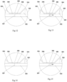
- the present invention relates to a multi-lined detection device 501, including a bottom card 502, at least two test strips 503 located above the bottom card and arranged side by side, and at least two sealing films 504 located above the bottom card and the test strips.
- these sealing films 504 each form a cavity 505 with the bottom card 502 in the area where the test strip 503 is located, and a bonding band 506 connecting said sealing film to the bottom card is formed around the cavity (please refer to Figs. 12 to 15 ).
- the test strip 503 is received in the cavity 505.
- the bottom card 502 forms an incompletely disconnected cutting line 507 (as shown by the dashed line in Fig.
- two adjacent sealing films 504 are completely disconnected in the area between the two adjacent bonding bands 506 to form a completely disconnected notch 508.
- the notch 508 causes the two sealing films 504 to form a gap in the area between the two adjacent bonding bands 506, as shown in Fig. 9 .
- the gap may be between 0.05mm to 2.0mm, preferably, 0.1mm to 0.5mm.
- the design has the advantages that when two adjacent detection devices are torn, the tearing force cannot be transferred to the sealing films 504 of the adjacent detection devices because the two adjacent sealing films 504 are completely disconnected and have no connection between each other and generate no implication between them, thus not affecting the bonding formed by the adjacent sealing films 504 and the bottom card 502, so that the sealed packaging of the adjacent detection devices will not be damaged.
- the completely disconnected notch 508 provides convenience for detection of whether the two adjacent sealing films 504 are completely disconnected in the area between the two adjacent bonding bands 506, as the formation of the completely disconnected notch 508 is more convenient for detection through visual observation (not only including detection through human visual observation but also including detection through automated visual observation of equipment).
- test strip 503 is bonded to the bottom card 502 through viscose 515.
- the bottom card 502 is preferably made of a moisture-proof and oxidation-resistant PE or PP material, with its thickness preferably ranging from 0.1mm to 0.5mm, more preferably ranging from 0.2mm to 0.35mm.
- the sealing film 504 is preferably made of a moisture-proof and oxidation-resistant PE or PP or PET material, with its thickness preferably ranging from 0.05mm to 0.20mm, more preferably ranging from 0.08mm to 0.15mm. Since the thickness of the bottom card 502 is much greater than the thickness of the sealing film 504, the bottom card 502 has moderate rigidity and higher strength, while the sealing film 504 is softer and has better stretching resistance and tearing resistance performances, and both of them are suitable for producing products of the present invention on automated equipment.
- the incompletely disconnected cutting line 507 on the bottom card 502 is a discontinuous cutting line, which is formed by connecting segments 509 spaced in sequence and fractures 510 penetrating through the bottom card.
- the length L1 of the fracture 510 of the discontinuous cutting line ranges from 0.5mm to 10.0mm (ranging from value A to value B means greater than or equal to value A and less than or equal to value B, the same in the full text), and the length L2 of the connecting segment 509 of the discontinuous cutting line ranges from 0.1mm to 3.0mm; and more preferably, the length L1 of the fracture 510 of the discontinuous cutting line ranges from 1.0mm to 5.0mm, and the length L2 of the connecting segment 509 of the discontinuous cutting line ranges from 0.5mm to 1.5mm.
- the side of the bottom card 502 facing the sealing film 504 is an upper surface, the back side of which is a lower surface.
- the incompletely disconnected cutting line 507 on the bottom card 502 is a continuous cutting line not penetrating through the upper and lower surfaces of the bottom card.
- the cutting depth L4 of this continuous cutting line ranges from one fifth to four fifths of the thickness L5 of the bottom card.
- the continuous cutting line is preferably located on the upper surface of the bottom card, but may also be located on the lower surface of the bottom card.
- the incompletely disconnected cutting line 507 on the bottom card 502 may also be a combination of the discontinuous cutting line and the continuous cutting line as previously described, i.e., one part of the incompletely disconnected cutting line 507 is the discontinuous cutting line as described in Figs. 8 , 12 and 14 and the other part is the continuous cutting line as shown in Figs. 13, 15 and 17 .
- the at least two adjacent sealing films 504 are bonded to the bottom card 502 at the edge of its area between the two adjacent bonding bands 506.
- This embodiment has the advantages that the multi-lined detection device 501 in the present invention is compact in structure and small in size.
- the bottom card 502 has a first end 516 and a second end 517 in a direction parallel to the incompletely disconnected cutting line 507, wherein the shortest distance "D1" from the first end 516 to the bonding band 506 is greater than the shortest distance "D2" from the second end 517 to the bonding band 506.
- the bottom card 502 forms a completely disconnected opening 511, which is "U" shaped (as shown in Fig. 18 ) or "V" shaped (as shown in Fig. 19 ), at the junction of the first end 516 thereof and the incompletely disconnected cutting line 507.
- the purpose of providing the completely disconnected opening 511 is to use the completely disconnected opening 511 as a starting point for tearing, thereby facilitating separation of the two adjacent single detection devices 550.
- the first end 516 typically serves as a holding end for an operator to tear off the sealing film 504 from the bottom card 502.
- the completely disconnected opening 511 is located at the first end 516 of the bottom card 502, thus after tearing off the detection device from the completely disconnected opening 511, the sealing film 504 can be torn from the bottom card 502 directly without changing hands to expose the test strip 503 for detection, instead of changing hands and subsequently turning over the torn single detection device 550 (inverted) to tear the sealing film 504 from the bottom card 502, so that the operation is more convenient.
- the bonding band 506 that bonds the sealing film 504 to the bottom card 502 is a closed ring, and the cavity 505 receiving the test strip 503 is sealed by the closed bonding band 506.
- the closed ring described in the present invention means that the bonding band 506 is closed, rather than limiting its shape to a circular ring; and on the contrary, the structure may be as shown in Figs. 20 to 23 or may be a structure developed according to Figs. 20 to 23 .
- the bonding band 506 is formed by a binder 512 (e.g., glue or double-sided adhesive tape, etc.) (as shown in Fig. 3 ).
- the bonding band 506 is formed by fusing the bottom card 502 and the sealing film 504 under pressure and heat (as shown in Figs. 14, 15 and 28 ).
- the bottom card 502 has a thermally adhesive film on its side facing the sealing film 504, the thermally adhesive film bonding the sealing film 504 to the bottom card 502 when being subjected to pressure and heat, so as to form said bonding band 506 (not shown in the figure).
- the closed bonding band 506 includes an intermediate portion 513 and two ends 514 connected to the two ends of the intermediate portion, respectively.
- the intermediate portion 513 preferably is two straight lines parallel to each other.
- the width of the end 514 is substantially constant.
- the width of the end 514 gradually decreases from the intermediate portion of the bonding band to the two ends of the bonding band (in the direction shown by arrow "D" in Figs. 21 to 23 ).
- the end 514 is of a circular structure (as shown in Figs.
- the two ends 514 may also be a combination of any of the structures as shown in Figs. 21 to 23 .
- the embodiments shown in Figs. 24 the embodiments shown in Figs.
- Fig. 29 is a schematic view of tearing off a single detection device 550 from the multi-lined detection device 501 along the incompletely disconnected cutting line 507.
Landscapes
- Health & Medical Sciences (AREA)
- Engineering & Computer Science (AREA)
- Chemical & Material Sciences (AREA)
- Life Sciences & Earth Sciences (AREA)
- Physics & Mathematics (AREA)
- Biomedical Technology (AREA)
- General Health & Medical Sciences (AREA)
- Analytical Chemistry (AREA)
- Hematology (AREA)
- Pathology (AREA)
- General Physics & Mathematics (AREA)
- Immunology (AREA)
- Biochemistry (AREA)
- Chemical Kinetics & Catalysis (AREA)
- Food Science & Technology (AREA)
- Mechanical Engineering (AREA)
- Medicinal Chemistry (AREA)
- Molecular Biology (AREA)
- Urology & Nephrology (AREA)
- Clinical Laboratory Science (AREA)
- Biophysics (AREA)
- Optics & Photonics (AREA)
- Composite Materials (AREA)
- Plasma & Fusion (AREA)
- Packages (AREA)
- Investigating Or Analysing Biological Materials (AREA)
- Containers And Plastic Fillers For Packaging (AREA)
- Auxiliary Devices For And Details Of Packaging Control (AREA)
Description
- The present invention relates to a detection device, in particular to a multi-lined detection device suitable for automated production.
- Disposable detection kits for detection of diseases or other physical conditions using body fluids such as urine, blood or other tissue fluids of a human body have been commonly used all over the world, and their applications can be in laboratories operated by professionals, or at home, schools, shopping malls, road checkpoints, customs, etc. operated by non-professionals themselves. As shown in
Fig. 1 and Fig. 2 , such adetection kit 1 generally includes anupper cover 2, abottom plate 3 and atest strip 4, wherein theupper cover 2 and thebottom plate 3 are combined in such a manner as buckling, welding, glue adhering or the like, and thetest strip 4 is arranged on thebottom plate 3 and located between theupper cover 2 and thebottom plate 3. Theupper cover 2 includes asample addition hole 5 and an observation hole 6. A liquid sample for detection is applied to a test strip via thesample addition hole 5, and after the end of the detection, a detection result on the test strip is observed via the observation hole 6, and determined accordingly. - The
upper cover 2 and thebottom plate 3 of such detection kit as shown inFig. 1 and Fig. 2 , are made of plastic articles that are thermally injection molded, and they account for a large portion of the cost of the whole detection kit. Both theupper cover 2 and thebottom plate 3 have a certain height, and after their combination, the size of thewhole detection kit 1 increases, and is much larger than the size of thetest strip 4, increasing storage and transportation costs. Moreover, due to long degradation time of plastics, usage of a large amount of plastics does not comply with the concept of environmental protection.Such detection kit 1 has been packaged in an aluminum foil bag in factory to avoid bumping against the test strips in thedetection kit 1 during transportation; and an operator has to tear the aluminum foil bag when the kit is to be used, and then takes out of thedetection kit 1 for detection, so that the operation steps are tedious. Furthermore, such detection detection kit is not suitable for manufacturing by automated equipment, but requires a large amount of human power for manual assembly, the assembly process is boring and cumbersome, and long time of operation is prone to resulting in fatigue, burnout and errors, reducing the qualification rate of products, and increasing labor costs. - As the disposable detection kits have been widely used, in order to reduce the purchase costs of users, it is necessary to meet these needs with the lowest possible product cost and convenient usage mode. Particularly in the case of spreading of epidemic diseases, how to quickly promote such detection kits so that more people can afford to use and are willing to use such rapid detection kit products is a problem that needs to be solved at present.
- For example,
CN 205 854 944 U discloses a test paper class bubble cap formula packaging structure including: at least one aluminium foil bubble cap unit.CN 211 732 447 U relates to a packaging plate, in particular to a novel capsule medicine aluminum-plastic packaging plate including a substrate, wherein the base plate is rectangular; a plurality of rectangular openings which are formed in the base plate and every two adjacent rectangular openings are separated through a partition plate. Each rectangular opening is internally provided with a medicine bin used for containing capsule medicine.JP 2013220841 A US 2012/080353 A1 discloses a retail and storage pack of the blister card type for zinc-air button cells including a support, and a transparent plastics film fixed thereon and having cup-shaped stamp-outs for reception of the button cells, wherein the pack is divided into single pack regions which can respectively be torn off separately and each of which respectively comprises at least one of the cup-shaped stamp-outs, and wherein the support is provided with an adhesive layer to which button cells received in the cup-shaped stamp-outs adhere by their base, which bases are provided with air inlet openings. - An objective of the present invention is to provide a multi-lined detection device, by which automated production is easy to realize. The device is small in size, is low in production, packaging and transportation costs, and uses little plastic materials, so that it is very environmentally friendly. When the multi-lined detection device is split into at least two single detection devices, the sealed packaging of adjacent detection devices is not affected.
- In order to solve the above technical problems, the present invention provides a multi-lined detection device, comprising a bottom card, at least two test strips located above the bottom card and arranged side by side, and at least two sealing films located above the bottom card and the test strips, the thickness of the bottom card is greater than the thickness of the sealing film. Wherein, the at least two sealing films each form a cavity with the bottom card in the area where the test strip is located, and a bonding band connecting said sealing film to the bottom card is formed around the cavity. The test strip is received in the cavity. The bottom card forms a cutting line, which is incompletely disconnected, in an area between two adjacent bonding bands. The two adjacent sealing films are completely disconnected in the area between the two adjacent bonding bands.
- Further improvement of the present invention lies in that the incompletely disconnected cutting line on the bottom card comprises a discontinuous cutting line, a continuous cutting line or a combination thereof; the discontinuous cutting line is formed by connecting segments spaced in sequence and fractures penetrating through the bottom card; and the continuous cutting line is a cutting line not penetrating through the bottom card.
- Further improvement of the present invention lies in that the length of the connecting segment of the discontinuous cutting line ranges from 0.1mm to 3.0mm, the length of the fracture of the discontinuous cutting line ranges from 0.5mm to 10.0mm, and the cutting depth of the continuous cutting line ranges from one fifth to four fifths of the thickness of the bottom card.
- Further improvement of the present invention lies in that the bottom card has a first end and a second end in a direction parallel to the cutting line, wherein the shortest distance from the first end to the bonding band is greater than the shortest distance from the second end to the bonding band, and the bottom card forms a completely disconnected opening, which is "U" shaped or "V" shaped, at the junction of the first end thereof and the cutting line.
- Further improvement of the present invention lies in that the bonding band bonding the sealing film to the bottom card is closed, and the cavity for receiving the test strip is sealed by the closed bonding band.
- Further improvement of the present invention lies in that the closed bonding band comprises an intermediate portion and two ends connected to the two ends of the intermediate portion, respectively, wherein the width of at least the end close to the first end of the bottom card gradually decreases in the direction from the intermediate portion of the bonding band to the two ends of the bonding band. Further improvement of the present invention lies in that the intermediate portion is two straight lines parallel to each other, and at least the end close to the first end of the bottom card is of a circular structure or a triangular structure without a bottom edge or a trapezoidal structure without a bottom edge.
- Further improvement of the present invention lies in that a completely disconnected notch is formed between two adjacent sealing films.
- Further improvement of the present invention lies in that the test strip is bonded to the bottom card through viscose.
- Further improvement of the present invention lies in that the bottom card is made of a PE or PP material with the thickness ranging from 0.1mm to 0.5mm; and the sealing film is made of a PE or PP or PET material with the thickness ranging from 0.05mm to 0.20mm.
- The present is small in size and uses a little amount of materials, so that the packaging and transportation costs are low. Furthermore, since a relatively flexible material that can be rolled is used, it is suitable for automated production, greatly reducing labor intensity and production costs. In addition, since the two adjacent sealing films are completely disconnected, when the bottom card is torn, the adjacent sealing films are not torn and the sealed packaging of the adjacent detection devices is not affected.
- Moreover, in the technical solution of the present invention that the sealing film is completely cut off, when two adjacent detection devices are torn, the tearing force cannot be transferred to the sealing films of the adjacent detection devices because the two adjacent sealing films are completely disconnected and have no connection between each other and generate no implication between them, thus not affecting the bonding formed by the adjacent sealing films and the bottom card, so that the sealed packaging of the adjacent detection devices will not be damaged.
- Further, the present invention forms a completely disconnected notch between the two adjacent sealing films, and the completely disconnected notch provides convenience for detection of whether the two adjacent sealing films are completely disconnected in the area between the two adjacent bonding bands, as the formation of the completely disconnected notch is more convenient for visual observation. This design improves the probability of complete disconnection between two adjacent sealing films and reduces the probability of affecting adjacent sealing films when a single detection device is torn, resulting in better beneficial effects.
-
-
Fig. 1 is a stereoscopic exploded view of a detection kit in the prior art; -
Fig. 2 is a stereoscopic schematic view ofFig. 1 after combination; -
Fig. 3 is an exploded view of a first embodiment of a multi-lined detection device of the present invention; -
Fig. 4 is a partially combined view ofFig. 3 ; -
Fig. 5 is a top view of the multi-lined detection device of the present invention after removal of sealing films; -
Fig. 6 is a top view of the sealing film of the multi-lined detection device of the present invention; -
Fig. 7 is a top view ofFig. 3 after combination (the parts obscured by the sealing films are shown by dashed lines); -
Fig. 8 is a partially enlarged schematic view within circle AinFig. 5 ; -
Fig. 9 is a partially enlarged schematic view within circle B inFig. 6 ; -
Fig. 10 is a partially enlarged schematic view within circle CinFig. 7 ; -
Fig. 11 is a sectional view ofFig. 7 along line A-A; -
Fig. 12 is a partially enlarged view within circle DinFig. 11 ; -
Fig. 13 is schematic view of a modified design ofFig. 12 ; -
Fig. 14 is a schematic view of another modified design ofFig. 12 ; -
Fig. 15 is a schematic view of another modified design ofFig. 12 ; -
Fig. 16 is schematic view of a modified design ofFig. 5 ; -
Fig. 17 is a partially enlarged schematic view of a part within circle E inFig. 16 along line B-B; -
Fig. 18 is a schematic view of a modified design ofFig. 8 ; -
Fig. 19 is a schematic view of another modified design ofFig. 8 ; -
Fig. 20 is a top view of a single detection device of after removal of sealing films, in which the shadow lines represent a bonding band; -
Fig. 21 is schematic view of a modified design ofFig. 20 ; -
Fig. 22 is a schematic view of another modified design ofFig. 20 ; -
Fig. 23 is a schematic view of another modified design ofFig. 20 ; -
Fig. 24 is a partially enlarged schematic view within circle F inFig. 20 ; -
Fig. 25 is a partially enlarged schematic view within circle G inFig. 21 ; -
Fig. 26 is a partially enlarged schematic view within circle H inFig. 22 ; -
Fig. 27 is a partially enlarged schematic view within circle I inFig. 23 ; -
Fig. 28 is a schematic view of a modified design ofFig. 3 ; and -
Fig. 29 is a schematic top view after one of the detection devices in the multi-lined detection device of the present invention is torn off. - The technical solutions of the present invention will be further specified below through embodiments in conjunction with the drawings.
- Please refer to
Figs. 3 to 29 , the present invention relates to amulti-lined detection device 501, including abottom card 502, at least twotest strips 503 located above the bottom card and arranged side by side, and at least two sealingfilms 504 located above the bottom card and the test strips. Wherein, these sealingfilms 504 each form acavity 505 with thebottom card 502 in the area where thetest strip 503 is located, and abonding band 506 connecting said sealing film to the bottom card is formed around the cavity (please refer toFigs. 12 to 15 ). Thetest strip 503 is received in thecavity 505. Thebottom card 502 forms an incompletely disconnected cutting line 507 (as shown by the dashed line inFig. 5 ) in an area between twoadjacent bonding bands 506. In the embodiments shown inFigs. 12 to 15 , two adjacent sealingfilms 504 are completely disconnected in the area between the twoadjacent bonding bands 506 to form a completelydisconnected notch 508. Thenotch 508 causes the two sealingfilms 504 to form a gap in the area between the twoadjacent bonding bands 506, as shown inFig. 9 . The gap may be between 0.05mm to 2.0mm, preferably, 0.1mm to 0.5mm. The design has the advantages that when two adjacent detection devices are torn, the tearing force cannot be transferred to the sealingfilms 504 of the adjacent detection devices because the two adjacent sealingfilms 504 are completely disconnected and have no connection between each other and generate no implication between them, thus not affecting the bonding formed by the adjacent sealingfilms 504 and thebottom card 502, so that the sealed packaging of the adjacent detection devices will not be damaged. Further, the completelydisconnected notch 508 provides convenience for detection of whether the two adjacent sealingfilms 504 are completely disconnected in the area between the twoadjacent bonding bands 506, as the formation of the completelydisconnected notch 508 is more convenient for detection through visual observation (not only including detection through human visual observation but also including detection through automated visual observation of equipment). This design improves the reliability of completely disconnecting two adjacent sealingfilms 504 and reduces the probability of affecting adjacent sealingfilms 504 when a single detection device is torn, resulting in better beneficial effects. Thetest strip 503 is bonded to thebottom card 502 throughviscose 515. - The
bottom card 502 is preferably made of a moisture-proof and oxidation-resistant PE or PP material, with its thickness preferably ranging from 0.1mm to 0.5mm, more preferably ranging from 0.2mm to 0.35mm. The sealingfilm 504 is preferably made of a moisture-proof and oxidation-resistant PE or PP or PET material, with its thickness preferably ranging from 0.05mm to 0.20mm, more preferably ranging from 0.08mm to 0.15mm. Since the thickness of thebottom card 502 is much greater than the thickness of the sealingfilm 504, thebottom card 502 has moderate rigidity and higher strength, while the sealingfilm 504 is softer and has better stretching resistance and tearing resistance performances, and both of them are suitable for producing products of the present invention on automated equipment. - In the embodiment shown in
Fig. 8 , the incompletely disconnected cuttingline 507 on thebottom card 502 is a discontinuous cutting line, which is formed by connectingsegments 509 spaced in sequence andfractures 510 penetrating through the bottom card. The longer the connectingsegment 509 is, the better the connecting stability is (the lower the probability of improper separation of thebottom card 502 is), but the larger the difficulty of separating thebottom card 502 along the incompletely disconnected cuttingline 507 is; and in contrary, the shorter the connectingsegment 509 is, the worse the connecting stability is (the higher the probability of improper separation of thebottom card 502 is), but the smaller the difficulty of separating thebottom card 502 along the incompletely disconnected cuttingline 507 is. Therefore, it is necessary to properly select the lengths of the connectingsegment 509 and thefracture 510. Preferably, the length L1 of thefracture 510 of the discontinuous cutting line ranges from 0.5mm to 10.0mm (ranging from value A to value B means greater than or equal to value A and less than or equal to value B, the same in the full text), and the length L2 of the connectingsegment 509 of the discontinuous cutting line ranges from 0.1mm to 3.0mm; and more preferably, the length L1 of thefracture 510 of the discontinuous cutting line ranges from 1.0mm to 5.0mm, and the length L2 of the connectingsegment 509 of the discontinuous cutting line ranges from 0.5mm to 1.5mm. - The side of the
bottom card 502 facing the sealingfilm 504 is an upper surface, the back side of which is a lower surface. In the embodiments shown inFigs. 13, 15 and17 , the incompletely disconnected cuttingline 507 on thebottom card 502 is a continuous cutting line not penetrating through the upper and lower surfaces of the bottom card. Preferably, the cutting depth L4 of this continuous cutting line ranges from one fifth to four fifths of the thickness L5 of the bottom card. The continuous cutting line is preferably located on the upper surface of the bottom card, but may also be located on the lower surface of the bottom card. - In another embodiment (not shown in the figure), the incompletely disconnected cutting
line 507 on thebottom card 502 may also be a combination of the discontinuous cutting line and the continuous cutting line as previously described, i.e., one part of the incompletely disconnected cuttingline 507 is the discontinuous cutting line as described inFigs. 8 ,12 and 14 and the other part is the continuous cutting line as shown inFigs. 13, 15 and17 . - In the embodiments shown in
Figs. 12 to 15 , the at least two adjacent sealingfilms 504 are bonded to thebottom card 502 at the edge of its area between the twoadjacent bonding bands 506. This embodiment has the advantages that themulti-lined detection device 501 in the present invention is compact in structure and small in size. - Please refer to
Fig. 7 , thebottom card 502 has afirst end 516 and asecond end 517 in a direction parallel to the incompletely disconnected cuttingline 507, wherein the shortest distance "D1" from thefirst end 516 to thebonding band 506 is greater than the shortest distance "D2" from thesecond end 517 to thebonding band 506. As shown inFigs. 18 and 19 , thebottom card 502 forms a completely disconnectedopening 511, which is "U" shaped (as shown inFig. 18 ) or "V" shaped (as shown inFig. 19 ), at the junction of thefirst end 516 thereof and the incompletely disconnected cuttingline 507. The purpose of providing the completely disconnectedopening 511 is to use the completely disconnectedopening 511 as a starting point for tearing, thereby facilitating separation of the two adjacentsingle detection devices 550. Thefirst end 516 typically serves as a holding end for an operator to tear off the sealingfilm 504 from thebottom card 502. Preferably, the completely disconnectedopening 511 is located at thefirst end 516 of thebottom card 502, thus after tearing off the detection device from the completely disconnectedopening 511, the sealingfilm 504 can be torn from thebottom card 502 directly without changing hands to expose thetest strip 503 for detection, instead of changing hands and subsequently turning over the torn single detection device 550 (inverted) to tear thesealing film 504 from thebottom card 502, so that the operation is more convenient. - Please refer to
Figs. 7, 11 andFigs. 20 to 23 , thebonding band 506 that bonds the sealingfilm 504 to thebottom card 502 is a closed ring, and thecavity 505 receiving thetest strip 503 is sealed by theclosed bonding band 506. The closed ring described in the present invention means that thebonding band 506 is closed, rather than limiting its shape to a circular ring; and on the contrary, the structure may be as shown inFigs. 20 to 23 or may be a structure developed according toFigs. 20 to 23 . In one embodiment, thebonding band 506 is formed by a binder 512 (e.g., glue or double-sided adhesive tape, etc.) (as shown inFig. 3 ). In another embodiment, no binder is used and thebonding band 506 is formed by fusing thebottom card 502 and thesealing film 504 under pressure and heat (as shown inFigs. 14, 15 and28 ). In another embodiment, thebottom card 502 has a thermally adhesive film on its side facing the sealingfilm 504, the thermally adhesive film bonding thesealing film 504 to thebottom card 502 when being subjected to pressure and heat, so as to form said bonding band 506 (not shown in the figure). - Please refer to
Figs. 20 to 27 , theclosed bonding band 506 includes anintermediate portion 513 and twoends 514 connected to the two ends of the intermediate portion, respectively. Theintermediate portion 513 preferably is two straight lines parallel to each other. In the embodiments shown inFig. 20 and Fig. 24 , the width of theend 514 is substantially constant. In the embodiment shown inFigs. 21 to 23 andFigs. 25 to 27 , the width of theend 514 gradually decreases from the intermediate portion of the bonding band to the two ends of the bonding band (in the direction shown by arrow "D" inFigs. 21 to 23 ). Preferably, theend 514 is of a circular structure (as shown inFigs. 21 and 25 ) or a triangular structure without a bottom edge (as shown inFigs. 22 and26 ) or a trapezoidal structure without a bottom edge (as shown inFigs. 23 and27 ). In another embodiment, the two ends 514 may also be a combination of any of the structures as shown inFigs. 21 to 23 . In contrast to the embodiment shown inFig. 24 , the embodiments shown inFigs. 25 to 27 have the advantages that the lengths of tear lines L1', L2', (L3'+L4'), tear lines L1", L2‴, (L3"+L4") and tear lines L1‴, L2'", (L3" + L4") are smaller than the lengths of tear lines L1, L2, and (L3+L4) inFig. 24 , respectively, i.e., L1' < L1, L2' < L2, (L3' + L4') < (L3+L4), and so on for others. This has the advantages that in the tearing process, the bonding force between the sealingfilm 504 and thebottom card 502 is smaller, so that it is easier to tear and separate thesealing film 504 from thebottom card 502.Fig. 29 is a schematic view of tearing off asingle detection device 550 from themulti-lined detection device 501 along the incompletely disconnected cuttingline 507. - The above description is only the specific implementations of the present invention, and is not thereby limiting the scope claimed for protection by the present invention.
Claims (10)
- A multi-lined detection device (501), comprising a bottom card (502), at least two test strips (503) located above the bottom card (502) and arranged side by side, and at least two sealing films (504) located above the bottom card (502) and the test strips (503), the thickness of the bottom card (502) is greater than the thickness of the sealing film (504), wherein the at least two sealing films (504) each form a cavity (505) with the bottom card (502) in the area where the test strip (503) is located, and a bonding band (506) connecting said sealing film (504) to the bottom card (502) is formed around the cavity (505); the test strip (503) is received in the cavity (505); and the bottom card (502) forms a cutting line, which is incompletely disconnected, in an area between two adjacent bonding bands (506); and two adjacent sealing films (504) are completely disconnected in the area between the two adjacent bonding bands (506).
- The multi-lined detection device (501) of claim 1, wherein the incompletely disconnected cutting line (507) on the bottom card (502) comprises a discontinuous cutting line, a continuous cutting line or a combination thereof; the discontinuous cutting line is formed by connecting segments (509) spaced in sequence and fractures (510) penetrating through the bottom card (502); and the continuous cutting line is a cutting line not penetrating through the bottom card (502).
- The multi-lined detection device (501) of claim 2, wherein the length of the connecting segment (509) of the discontinuous cutting line ranges from 0.1mm to 3.0mm, the length of the fracture (510) of the discontinuous cutting line ranges from 0.5mm to 10.0mm, and the cutting depth of the continuous cutting line ranges from one fifth to four fifths of the thickness of the bottom card (502).
- The multi-lined detection device (501) of claim 2, wherein the bottom card (502) has a first end (516) and a second end (517) in a direction parallel to the cutting line, wherein the shortest distance from the first end (516) to the bonding band (506) is greater than the shortest distance from the second end (517) to the bonding band (506), and the bottom card (502) forms a completely disconnected opening (511), which is "U" shaped or "V" shaped, at the junction of the first end (516) thereof and the cutting line.
- The multi-lined detection device (501) of claim 4, wherein the bonding band (506) bonding the sealing film (504) to the bottom card (502) is closed, and the cavity (505) for receiving the test strip (503) is sealed by the closed bonding band (506).
- The multi-lined detection device (501) of claim 5, wherein the closed bonding band (506) comprises an intermediate portion (513) and two ends (514) connected to the two ends (514) of the intermediate portion (513), respectively, wherein the width of at least the end (514) close to the first end (516) of the bottom card (502) gradually decreases in the direction from the intermediate portion (513) of the bonding band (506) to the two ends (514) of the bonding band (506).
- The multi-lined detection device (501) of claim 6, wherein the intermediate portion (513) is two straight lines parallel to each other, and at least the end (514) close to the first end (516) of the bottom card (502) is of a circular structure or a triangular structure without a bottom edge or a trapezoidal structure without a bottom edge.
- The multi-lined detection device (501) of claim 1, wherein a completely disconnected notch (508) is formed between two adjacent sealing films (504).
- The multi-lined detection device (501) of claim 1, wherein the test strip (503) is bonded to the bottom card (502) through viscose (515).
- The multi-lined detection device (501) of claim 1, wherein the bottom card (502) is made of a PE or PP material with the thickness ranging from 0.1mm to 0.5mm; and the sealing film (504) is made of a PE or PP or PET material with the thickness ranging from 0.05mm to 0.20mm.
Applications Claiming Priority (3)
| Application Number | Priority Date | Filing Date | Title |
|---|---|---|---|
| CN202210370196 | 2022-04-08 | ||
| CN202210447619.1A CN114563557B (en) | 2022-04-08 | 2022-04-26 | Multi-row detection device |
| PCT/CN2022/132931 WO2023193446A1 (en) | 2022-04-08 | 2022-11-18 | Multi-row testing device |
Publications (3)
| Publication Number | Publication Date |
|---|---|
| EP4279414A1 EP4279414A1 (en) | 2023-11-22 |
| EP4279414A4 EP4279414A4 (en) | 2023-11-22 |
| EP4279414B1 true EP4279414B1 (en) | 2025-01-22 |
Family
ID=81667155
Family Applications (2)
| Application Number | Title | Priority Date | Filing Date |
|---|---|---|---|
| EP22871062.0A Active EP4279414B1 (en) | 2022-04-08 | 2022-11-18 | Multi-row testing device |
| EP22871049.7A Active EP4286120B1 (en) | 2022-04-08 | 2022-11-18 | Manufacturing method for multi-row detection device |
Family Applications After (1)
| Application Number | Title | Priority Date | Filing Date |
|---|---|---|---|
| EP22871049.7A Active EP4286120B1 (en) | 2022-04-08 | 2022-11-18 | Manufacturing method for multi-row detection device |
Country Status (5)
| Country | Link |
|---|---|
| US (1) | US20250214077A1 (en) |
| EP (2) | EP4279414B1 (en) |
| CN (5) | CN217688977U (en) |
| ES (2) | ES3064870T3 (en) |
| WO (2) | WO2023193445A1 (en) |
Families Citing this family (2)
| Publication number | Priority date | Publication date | Assignee | Title |
|---|---|---|---|---|
| CN217688977U (en) * | 2022-04-08 | 2022-10-28 | 艾康生物技术(杭州)有限公司 | Multi-row immunoassay device |
| CN117074396A (en) * | 2023-08-17 | 2023-11-17 | 内蒙古威胜纳米材料有限公司 | Test paper with dampproofing packing |
Family Cites Families (49)
| Publication number | Priority date | Publication date | Assignee | Title |
|---|---|---|---|---|
| US2700556A (en) * | 1951-08-17 | 1955-01-25 | Ibm | Continuous form with separable portions |
| JP3020311B2 (en) * | 1991-07-03 | 2000-03-15 | 広栄化学工業株式会社 | Cutting device for heating element production |
| DE4439224A1 (en) * | 1994-11-03 | 1996-05-09 | Bosch Gmbh Robert | Device for processing a film strand having cups |
| JPH10152167A (en) * | 1996-11-19 | 1998-06-09 | Dainippon Printing Co Ltd | Package |
| US5794774A (en) * | 1997-05-12 | 1998-08-18 | Porcelli; V. Lorenzo | Disposable oral hygiene applicator |
| DE29717187U1 (en) * | 1997-09-25 | 1999-01-28 | THERA Patent GmbH & Co. KG Gesellschaft für industrielle Schutzrechte, 82229 Seefeld | Resealable packaging |
| US6033627A (en) * | 1997-11-17 | 2000-03-07 | Smithkline Diagnostics, Inc. | Bevel closure assay device housing |
| CN2329621Y (en) * | 1998-06-29 | 1999-07-21 | 姚崇德 | Test paper sealing packing piece |
| AU1555500A (en) * | 1998-12-09 | 2000-06-26 | Carl Edelmann Gmbh & Co. Kg | Packaging for planiform objects/products |
| CN2366849Y (en) * | 1999-04-22 | 2000-03-01 | 罗福海 | Detecting card for external diagnosis |
| JP2004114582A (en) * | 2002-09-27 | 2004-04-15 | Mitsubishi Plastics Ind Ltd | Polyester sheet and package for thermoforming |
| CA2421989A1 (en) * | 2003-03-13 | 2004-09-13 | Henrikus Vink | Cigarette package |
| NL1023550C2 (en) * | 2003-05-27 | 2004-11-30 | Beek Bv A A Ter | Packaging for baking and use thereof. |
| HUE039852T2 (en) * | 2003-06-20 | 2019-02-28 | Hoffmann La Roche | Method and reagent for producing narrow, homogenous reagent strips |
| DE102004047445B4 (en) * | 2004-09-30 | 2007-05-31 | Lts Lohmann Therapie-Systeme Ag | Non-resealable packaging for health-endangering products, use of the packaging, and methods of making the same |
| FR2876986B1 (en) * | 2004-10-25 | 2006-12-29 | Cryolog Sa Sa | METHOD FOR HERMETICALLY AND HIGH-FREQUENCY CONDITIONING, AN ACTIVE GEL RICH IN WATER AND / OR CONTAINING MICRO-ORGANISMS |
| JP2006182364A (en) * | 2004-12-27 | 2006-07-13 | Aji Nihon Kk | Machining tool for packaging body connecting belt, machining apparatus for packaging body connecting belt, and packaging body manufacturing system and method |
| GB0502252D0 (en) * | 2005-02-03 | 2005-03-09 | Meridica Ltd | Container for medical products and method of sealing thereof |
| DE102005033875A1 (en) * | 2005-07-20 | 2007-02-01 | Mapa Gmbh Gummi- Und Plastikwerke | Packaging for condoms |
| DE102005035705A1 (en) * | 2005-07-27 | 2007-02-01 | Boehringer Ingelheim Pharma Gmbh & Co. Kg | pharmaceutical blister |
| JP2007178376A (en) * | 2005-12-28 | 2007-07-12 | Sysmex Corp | Test piece storing body and its manufacturing method |
| EP1967465A1 (en) * | 2007-03-05 | 2008-09-10 | Mars Incorporated | Packaged products and array or bandoleer of packaged products |
| JP5184802B2 (en) * | 2007-03-27 | 2013-04-17 | 大日本印刷株式会社 | Manufacturing method and apparatus for sealed bag |
| CN201058704Y (en) * | 2007-07-25 | 2008-05-14 | 修正药业集团股份有限公司 | Drug plastic-aluminum packing plate |
| CN201076603Y (en) * | 2007-09-28 | 2008-06-25 | 宁波立华制药有限公司 | Medicine clad plate |
| US20100051455A1 (en) * | 2008-08-26 | 2010-03-04 | Roche Diagnostics Operations, Inc. | Biosensor test strip cards |
| ES2546503T3 (en) * | 2008-09-08 | 2015-09-24 | Lts Lohmann Therapie-Systeme Ag | Individual safe dose container for children for transdermal therapeutic systems or administration forms in sheet form |
| DE102009025471A1 (en) * | 2009-06-12 | 2010-12-16 | Varta Microbattery Gmbh | Sales and storage pack for zinc / air button cells |
| CN202594092U (en) * | 2012-03-08 | 2012-12-12 | 宁波日鼎电子科技有限公司 | Packaging structure of connectors |
| JP5997924B2 (en) * | 2012-04-18 | 2016-09-28 | 富士製薬工業株式会社 | Easy-open blister pack |
| JP2014118193A (en) * | 2012-12-18 | 2014-06-30 | Sekisui Giken:Kk | Container connected body |
| CN103057765A (en) * | 2013-01-25 | 2013-04-24 | 宁夏松久自动化设备有限公司 | Packaging film cutting device |
| JP2014176597A (en) * | 2013-07-04 | 2014-09-25 | Kanae Co Ltd | Label |
| CN203688538U (en) * | 2014-01-16 | 2014-07-02 | 北京亦庄国际诊断试剂技术有限公司 | Encapsulation test strip and long test strip band |
| KR20160072721A (en) * | 2014-12-15 | 2016-06-23 | (주)크레템 | Medicine wrapping apparatus |
| CN204789585U (en) * | 2015-07-23 | 2015-11-18 | 深圳市检验检疫科学研究院 | A immunity chromatography test paper for detecting former breast of ox |
| WO2017019844A1 (en) * | 2015-07-28 | 2017-02-02 | ApolloDX, LLC | Test strip for diagnostic testing |
| CN205854944U (en) * | 2016-07-04 | 2017-01-04 | 万华普曼生物工程有限公司 | A kind of Test paper class bubble-cap type packaging structure |
| CN207060848U (en) * | 2017-03-01 | 2018-03-02 | 秦皇岛博硕光电设备股份有限公司 | The sealing plate of solid chemicals inner container |
| CN108051596A (en) * | 2018-01-18 | 2018-05-18 | 凌中鑫 | A kind of Woundless blood sugar test paper and preparation method thereof |
| CN208516076U (en) * | 2018-05-17 | 2019-02-19 | 澳诺(中国)制药有限公司 | A kind of plastic packpage bottle of oral liquid |
| CN108688854A (en) * | 2018-05-23 | 2018-10-23 | 东莞理工学院 | Double-side film sealing packaging machine for blade |
| CN209192696U (en) * | 2018-10-24 | 2019-08-02 | 福建凯龙医疗卫生材料有限公司 | Easily take off moisture absorption packaging bag |
| CN211732447U (en) * | 2020-03-18 | 2020-10-23 | 郑州韩都药业集团有限公司 | Novel capsule medicine plastic-aluminum packing plate |
| CN211845668U (en) * | 2020-03-30 | 2020-11-03 | 南京信息工程大学 | a sauce box |
| CN212474409U (en) * | 2020-05-08 | 2021-02-05 | 湖南可孚医疗设备有限公司 | Test paper storage cylinder |
| CN112027193B (en) * | 2020-09-21 | 2024-11-26 | 苏州怡拓生物传感技术有限公司 | A multi-row test strip automatic bagging production equipment |
| CN213081605U (en) * | 2020-09-21 | 2021-04-30 | 苏州怡拓生物传感技术有限公司 | Test strip rolling-cutting material distribution mechanism |
| CN217688977U (en) * | 2022-04-08 | 2022-10-28 | 艾康生物技术(杭州)有限公司 | Multi-row immunoassay device |
-
2022
- 2022-04-26 CN CN202220986747.9U patent/CN217688977U/en active Active
- 2022-04-26 CN CN202210442651.0A patent/CN114536470B/en active Active
- 2022-04-26 CN CN202221004050.3U patent/CN218099199U/en active Active
- 2022-04-26 CN CN202210447619.1A patent/CN114563557B/en active Active
- 2022-04-27 CN CN202221016671.3U patent/CN218766938U/en active Active
- 2022-11-18 ES ES22871049T patent/ES3064870T3/en active Active
- 2022-11-18 EP EP22871062.0A patent/EP4279414B1/en active Active
- 2022-11-18 ES ES22871062T patent/ES3022259T3/en active Active
- 2022-11-18 EP EP22871049.7A patent/EP4286120B1/en active Active
- 2022-11-18 US US18/850,061 patent/US20250214077A1/en active Pending
- 2022-11-18 WO PCT/CN2022/132929 patent/WO2023193445A1/en not_active Ceased
- 2022-11-18 WO PCT/CN2022/132931 patent/WO2023193446A1/en not_active Ceased
Also Published As
| Publication number | Publication date |
|---|---|
| CN114536470B (en) | 2022-08-12 |
| CN218766938U (en) | 2023-03-28 |
| EP4286120A4 (en) | 2024-08-28 |
| EP4286120A1 (en) | 2023-12-06 |
| CN217688977U (en) | 2022-10-28 |
| EP4279414A1 (en) | 2023-11-22 |
| CN114563557B (en) | 2022-09-13 |
| CN114536470A (en) | 2022-05-27 |
| ES3064870T3 (en) | 2026-04-29 |
| WO2023193445A1 (en) | 2023-10-12 |
| WO2023193446A1 (en) | 2023-10-12 |
| EP4286120B1 (en) | 2026-01-14 |
| CN218099199U (en) | 2022-12-20 |
| CN114563557A (en) | 2022-05-31 |
| ES3022259T3 (en) | 2025-05-28 |
| US20250214077A1 (en) | 2025-07-03 |
Similar Documents
| Publication | Publication Date | Title |
|---|---|---|
| JP5611975B2 (en) | Liquid container and manufacturing method | |
| ES2871975T3 (en) | Multilayer film and reusable closure film container | |
| RU2688856C2 (en) | Multilayer film and film package made with possibility of repeated closing | |
| EP4279414A1 (en) | Multi-row testing device | |
| JP6970232B2 (en) | Multilayer film and resealable film package | |
| US5348191A (en) | Device for storage and dispensation of measured quantities of pasty materials and process for its embodiment | |
| JP6111537B2 (en) | Paper container manufacturing method | |
| CN103781711B (en) | Funnel component, employ the packing container of funnel component | |
| CN102190122A (en) | Blister packaging and manufacturing method thereof | |
| EP1517384A1 (en) | Battery package and method for measuring characteristics of battery contained in battery package | |
| KR200475204Y1 (en) | Pouch for easy to mix two contents | |
| JP3610754B2 (en) | Multi-room pouch with a branched small room | |
| KR200475206Y1 (en) | Pouch for easy to mix two contents | |
| JP3935565B2 (en) | Packaging bag | |
| JP2018030593A (en) | Pouch container with support member and pouch container forming the same | |
| JP3131745B2 (en) | Blister pack container | |
| RU2204172C2 (en) | Exhibit holder | |
| JP3467227B2 (en) | Easy peeling buffer envelope | |
| JP2016016897A (en) | Packaging bag | |
| CN213893299U (en) | From taking strip of paper used for sealing box bag integral type cutlery box | |
| CN212713340U (en) | Novel release film structure for adhesive tape | |
| JP5103437B2 (en) | Packaging bag with zipper | |
| JP4935016B2 (en) | Resealable packaging bag | |
| JP3132567U (en) | Patch packaging bag | |
| JP2003142055A (en) | Battery pack with product promotion label |
Legal Events
| Date | Code | Title | Description |
|---|---|---|---|
| STAA | Information on the status of an ep patent application or granted ep patent |
Free format text: STATUS: UNKNOWN |
|
| STAA | Information on the status of an ep patent application or granted ep patent |
Free format text: STATUS: THE INTERNATIONAL PUBLICATION HAS BEEN MADE |
|
| PUAI | Public reference made under article 153(3) epc to a published international application that has entered the european phase |
Free format text: ORIGINAL CODE: 0009012 |
|
| STAA | Information on the status of an ep patent application or granted ep patent |
Free format text: STATUS: REQUEST FOR EXAMINATION WAS MADE |
|
| 17P | Request for examination filed |
Effective date: 20230329 |
|
| A4 | Supplementary search report drawn up and despatched |
Effective date: 20230918 |
|
| AK | Designated contracting states |
Kind code of ref document: A1 Designated state(s): AL AT BE BG CH CY CZ DE DK EE ES FI FR GB GR HR HU IE IS IT LI LT LU LV MC ME MK MT NL NO PL PT RO RS SE SI SK SM TR |
|
| REG | Reference to a national code |
Ref country code: DE Ref legal event code: R079 Free format text: PREVIOUS MAIN CLASS: B65D0075340000 Ipc: B65D0075320000 Ref document number: 602022009877 Country of ref document: DE |
|
| RIC1 | Information provided on ipc code assigned before grant |
Ipc: G01N 33/48 20060101ALI20240723BHEP Ipc: B65D 75/52 20060101ALI20240723BHEP Ipc: B65D 75/32 20060101AFI20240723BHEP |
|
| GRAP | Despatch of communication of intention to grant a patent |
Free format text: ORIGINAL CODE: EPIDOSNIGR1 |
|
| STAA | Information on the status of an ep patent application or granted ep patent |
Free format text: STATUS: GRANT OF PATENT IS INTENDED |
|
| DAV | Request for validation of the european patent (deleted) | ||
| DAX | Request for extension of the european patent (deleted) | ||
| INTG | Intention to grant announced |
Effective date: 20240830 |
|
| GRAS | Grant fee paid |
Free format text: ORIGINAL CODE: EPIDOSNIGR3 |
|
| GRAA | (expected) grant |
Free format text: ORIGINAL CODE: 0009210 |
|
| STAA | Information on the status of an ep patent application or granted ep patent |
Free format text: STATUS: THE PATENT HAS BEEN GRANTED |
|
| AK | Designated contracting states |
Kind code of ref document: B1 Designated state(s): AL AT BE BG CH CY CZ DE DK EE ES FI FR GB GR HR HU IE IS IT LI LT LU LV MC ME MK MT NL NO PL PT RO RS SE SI SK SM TR |
|
| REG | Reference to a national code |
Ref country code: GB Ref legal event code: FG4D |
|
| REG | Reference to a national code |
Ref country code: CH Ref legal event code: EP |
|
| REG | Reference to a national code |
Ref country code: IE Ref legal event code: FG4D |
|
| REG | Reference to a national code |
Ref country code: DE Ref legal event code: R096 Ref document number: 602022009877 Country of ref document: DE |
|
| P01 | Opt-out of the competence of the unified patent court (upc) registered |
Free format text: CASE NUMBER: APP_9295/2025 Effective date: 20250225 |
|
| REG | Reference to a national code |
Ref country code: DE Ref legal event code: R081 Ref document number: 602022009877 Country of ref document: DE Owner name: LEADWAY (HK) LTD., HK Free format text: FORMER OWNER: ACON BIOTECH (HANGZHOU) CO., LTD., HANGZHOU, ZHEJIANG, CN |
|
| RAP2 | Party data changed (patent owner data changed or rights of a patent transferred) |
Owner name: LEADWAY (HK) LIMITED |
|
| REG | Reference to a national code |
Ref country code: GB Ref legal event code: 732E Free format text: REGISTERED BETWEEN 20250424 AND 20250430 |
|
| REG | Reference to a national code |
Ref country code: NL Ref legal event code: MP Effective date: 20250122 Ref country code: ES Ref legal event code: FG2A Ref document number: 3022259 Country of ref document: ES Kind code of ref document: T3 Effective date: 20250528 |
|
| PG25 | Lapsed in a contracting state [announced via postgrant information from national office to epo] |
Ref country code: NL Free format text: LAPSE BECAUSE OF FAILURE TO SUBMIT A TRANSLATION OF THE DESCRIPTION OR TO PAY THE FEE WITHIN THE PRESCRIBED TIME-LIMIT Effective date: 20250122 |
|
| PG25 | Lapsed in a contracting state [announced via postgrant information from national office to epo] |
Ref country code: RS Free format text: LAPSE BECAUSE OF FAILURE TO SUBMIT A TRANSLATION OF THE DESCRIPTION OR TO PAY THE FEE WITHIN THE PRESCRIBED TIME-LIMIT Effective date: 20250422 |
|
| PG25 | Lapsed in a contracting state [announced via postgrant information from national office to epo] |
Ref country code: FI Free format text: LAPSE BECAUSE OF FAILURE TO SUBMIT A TRANSLATION OF THE DESCRIPTION OR TO PAY THE FEE WITHIN THE PRESCRIBED TIME-LIMIT Effective date: 20250122 |
|
| PG25 | Lapsed in a contracting state [announced via postgrant information from national office to epo] |
Ref country code: PL Free format text: LAPSE BECAUSE OF FAILURE TO SUBMIT A TRANSLATION OF THE DESCRIPTION OR TO PAY THE FEE WITHIN THE PRESCRIBED TIME-LIMIT Effective date: 20250122 |
|
| REG | Reference to a national code |
Ref country code: LT Ref legal event code: MG9D |
|
| PG25 | Lapsed in a contracting state [announced via postgrant information from national office to epo] |
Ref country code: IS Free format text: LAPSE BECAUSE OF FAILURE TO SUBMIT A TRANSLATION OF THE DESCRIPTION OR TO PAY THE FEE WITHIN THE PRESCRIBED TIME-LIMIT Effective date: 20250522 Ref country code: NO Free format text: LAPSE BECAUSE OF FAILURE TO SUBMIT A TRANSLATION OF THE DESCRIPTION OR TO PAY THE FEE WITHIN THE PRESCRIBED TIME-LIMIT Effective date: 20250422 |
|
| REG | Reference to a national code |
Ref country code: AT Ref legal event code: MK05 Ref document number: 1761334 Country of ref document: AT Kind code of ref document: T Effective date: 20250122 |
|
| PG25 | Lapsed in a contracting state [announced via postgrant information from national office to epo] |
Ref country code: HR Free format text: LAPSE BECAUSE OF FAILURE TO SUBMIT A TRANSLATION OF THE DESCRIPTION OR TO PAY THE FEE WITHIN THE PRESCRIBED TIME-LIMIT Effective date: 20250122 |
|
| PG25 | Lapsed in a contracting state [announced via postgrant information from national office to epo] |
Ref country code: LV Free format text: LAPSE BECAUSE OF FAILURE TO SUBMIT A TRANSLATION OF THE DESCRIPTION OR TO PAY THE FEE WITHIN THE PRESCRIBED TIME-LIMIT Effective date: 20250122 Ref country code: PT Free format text: LAPSE BECAUSE OF FAILURE TO SUBMIT A TRANSLATION OF THE DESCRIPTION OR TO PAY THE FEE WITHIN THE PRESCRIBED TIME-LIMIT Effective date: 20250522 |
|
| PG25 | Lapsed in a contracting state [announced via postgrant information from national office to epo] |
Ref country code: BG Free format text: LAPSE BECAUSE OF FAILURE TO SUBMIT A TRANSLATION OF THE DESCRIPTION OR TO PAY THE FEE WITHIN THE PRESCRIBED TIME-LIMIT Effective date: 20250122 Ref country code: GR Free format text: LAPSE BECAUSE OF FAILURE TO SUBMIT A TRANSLATION OF THE DESCRIPTION OR TO PAY THE FEE WITHIN THE PRESCRIBED TIME-LIMIT Effective date: 20250423 |
|
| PG25 | Lapsed in a contracting state [announced via postgrant information from national office to epo] |
Ref country code: AT Free format text: LAPSE BECAUSE OF FAILURE TO SUBMIT A TRANSLATION OF THE DESCRIPTION OR TO PAY THE FEE WITHIN THE PRESCRIBED TIME-LIMIT Effective date: 20250122 |
|
| PG25 | Lapsed in a contracting state [announced via postgrant information from national office to epo] |
Ref country code: SE Free format text: LAPSE BECAUSE OF FAILURE TO SUBMIT A TRANSLATION OF THE DESCRIPTION OR TO PAY THE FEE WITHIN THE PRESCRIBED TIME-LIMIT Effective date: 20250122 |
|
| PG25 | Lapsed in a contracting state [announced via postgrant information from national office to epo] |
Ref country code: SM Free format text: LAPSE BECAUSE OF FAILURE TO SUBMIT A TRANSLATION OF THE DESCRIPTION OR TO PAY THE FEE WITHIN THE PRESCRIBED TIME-LIMIT Effective date: 20250122 |
|
| PG25 | Lapsed in a contracting state [announced via postgrant information from national office to epo] |
Ref country code: DK Free format text: LAPSE BECAUSE OF FAILURE TO SUBMIT A TRANSLATION OF THE DESCRIPTION OR TO PAY THE FEE WITHIN THE PRESCRIBED TIME-LIMIT Effective date: 20250122 |
|
| PG25 | Lapsed in a contracting state [announced via postgrant information from national office to epo] |
Ref country code: CZ Free format text: LAPSE BECAUSE OF FAILURE TO SUBMIT A TRANSLATION OF THE DESCRIPTION OR TO PAY THE FEE WITHIN THE PRESCRIBED TIME-LIMIT Effective date: 20250122 Ref country code: EE Free format text: LAPSE BECAUSE OF FAILURE TO SUBMIT A TRANSLATION OF THE DESCRIPTION OR TO PAY THE FEE WITHIN THE PRESCRIBED TIME-LIMIT Effective date: 20250122 |
|
| REG | Reference to a national code |
Ref country code: DE Ref legal event code: R097 Ref document number: 602022009877 Country of ref document: DE |
|
| PG25 | Lapsed in a contracting state [announced via postgrant information from national office to epo] |
Ref country code: RO Free format text: LAPSE BECAUSE OF FAILURE TO SUBMIT A TRANSLATION OF THE DESCRIPTION OR TO PAY THE FEE WITHIN THE PRESCRIBED TIME-LIMIT Effective date: 20250122 |
|
| PG25 | Lapsed in a contracting state [announced via postgrant information from national office to epo] |
Ref country code: SK Free format text: LAPSE BECAUSE OF FAILURE TO SUBMIT A TRANSLATION OF THE DESCRIPTION OR TO PAY THE FEE WITHIN THE PRESCRIBED TIME-LIMIT Effective date: 20250122 |
|
| PLBE | No opposition filed within time limit |
Free format text: ORIGINAL CODE: 0009261 |
|
| STAA | Information on the status of an ep patent application or granted ep patent |
Free format text: STATUS: NO OPPOSITION FILED WITHIN TIME LIMIT |
|
| 26N | No opposition filed |
Effective date: 20251023 |
|
| PGFP | Annual fee paid to national office [announced via postgrant information from national office to epo] |
Ref country code: DE Payment date: 20251117 Year of fee payment: 4 |
|
| PGFP | Annual fee paid to national office [announced via postgrant information from national office to epo] |
Ref country code: IT Payment date: 20251201 Year of fee payment: 4 |
|
| PGFP | Annual fee paid to national office [announced via postgrant information from national office to epo] |
Ref country code: FR Payment date: 20251127 Year of fee payment: 4 |
|
| PGFP | Annual fee paid to national office [announced via postgrant information from national office to epo] |
Ref country code: ES Payment date: 20251210 Year of fee payment: 4 |