EP4278917B1 - Persönliche schutzvorrichtung - Google Patents
Persönliche schutzvorrichtung Download PDFInfo
- Publication number
- EP4278917B1 EP4278917B1 EP23174182.8A EP23174182A EP4278917B1 EP 4278917 B1 EP4278917 B1 EP 4278917B1 EP 23174182 A EP23174182 A EP 23174182A EP 4278917 B1 EP4278917 B1 EP 4278917B1
- Authority
- EP
- European Patent Office
- Prior art keywords
- protection device
- elements
- inflatable
- inflatable elements
- adjacent
- Prior art date
- Legal status (The legal status is an assumption and is not a legal conclusion. Google has not performed a legal analysis and makes no representation as to the accuracy of the status listed.)
- Active
Links
Images


Classifications
-
- A—HUMAN NECESSITIES
- A41—WEARING APPAREL
- A41D—OUTERWEAR; PROTECTIVE GARMENTS; ACCESSORIES
- A41D13/00—Professional, industrial or sporting protective garments, e.g. surgeons' gowns or garments protecting against blows or punches
- A41D13/015—Professional, industrial or sporting protective garments, e.g. surgeons' gowns or garments protecting against blows or punches with shock-absorbing means
- A41D13/018—Professional, industrial or sporting protective garments, e.g. surgeons' gowns or garments protecting against blows or punches with shock-absorbing means inflatable automatically
-
- A—HUMAN NECESSITIES
- A41—WEARING APPAREL
- A41D—OUTERWEAR; PROTECTIVE GARMENTS; ACCESSORIES
- A41D13/00—Professional, industrial or sporting protective garments, e.g. surgeons' gowns or garments protecting against blows or punches
- A41D13/015—Professional, industrial or sporting protective garments, e.g. surgeons' gowns or garments protecting against blows or punches with shock-absorbing means
- A41D13/0158—Professional, industrial or sporting protective garments, e.g. surgeons' gowns or garments protecting against blows or punches with shock-absorbing means having ventilation features
-
- A—HUMAN NECESSITIES
- A41—WEARING APPAREL
- A41D—OUTERWEAR; PROTECTIVE GARMENTS; ACCESSORIES
- A41D2300/00—Details of garments
- A41D2300/20—Inserts
- A41D2300/24—Folded inserts
-
- A—HUMAN NECESSITIES
- A41—WEARING APPAREL
- A41D—OUTERWEAR; PROTECTIVE GARMENTS; ACCESSORIES
- A41D2400/00—Functions or special features of garments
- A41D2400/10—Heat retention or warming
- A41D2400/14—Heat retention or warming inflatable
-
- A—HUMAN NECESSITIES
- A41—WEARING APPAREL
- A41D—OUTERWEAR; PROTECTIVE GARMENTS; ACCESSORIES
- A41D31/00—Materials specially adapted for outerwear
- A41D31/04—Materials specially adapted for outerwear characterised by special function or use
- A41D31/06—Thermally protective, e.g. insulating
-
- A—HUMAN NECESSITIES
- A41—WEARING APPAREL
- A41D—OUTERWEAR; PROTECTIVE GARMENTS; ACCESSORIES
- A41D31/00—Materials specially adapted for outerwear
- A41D31/04—Materials specially adapted for outerwear characterised by special function or use
- A41D31/14—Air permeable, i.e. capable of being penetrated by gases
Definitions
- the present disclosure relates in general to a personal protection device for protecting a user, wherein the device is preferably of the type which is wearable and/or can be associated with a wearable article, such as a garment.
- the protection device includes in particular an inflatable body which in the inflated condition, is designed to protect from impacts and/or falls a motorcycle rider or passenger or similar user, during a sporting and/or working and/or any other activity.
- the inflatable body is designed to provide protection from the cold.
- a known protection device is, for example, that described in European Patent EP3291697B1 .
- Such a device includes an inflatable element designed to assume an active inflated condition and a deflated rest condition.
- the inflatable element includes a knitted body, namely a body made by means of a knitting process.
- Said knitted body is a closed or at least tubular structure defining an inner region or area or chamber. This inner chamber is occupied at least partially by a plurality of joining threads which connect together opposite portions of the knitted body.
- the fact of providing a single knitted body has the advantage of limiting the manufacturing waste and minimizing the production time; in fact, the joining threads and meshes may be processed using a single knitting machine.
- the joining threads form part of single thread connected to the opposite portions of the knitted body. In particular, the thread passes along alternate sections and continuously between a first portion and a second portion of the knitted body.
- the inflatable element also includes sealing walls which are arranged externally and allow the inflation fluid to be contained for a predetermined period of time.
- the walls consist, for example, of a first sheet, or first wall, and of a second sheet, or second wall, which are fixed together along respective perimetral edges.
- Said first and second sheets made of impermeable material cover and line the knitted body on an outer side or outer surface.
- Such a wearable protection device is known from EP2373189B1 .
- Both the wearable devices have the advantage that they have, in the inflated condition, a flat mattress-like form which is particularly suitable and appropriate for insertion in a garment.
- An inflatable element designed in this manner while being very advantageous from many points of view, nevertheless has the drawback that it covers the body also in the deflated condition and does not always allow suitable breathability in the article of clothing in which it is incorporated or inserted.
- the inflatable element in the deflated condition may create a kind of bag around the user's body which does not allow a suitable throughflow of ventilation air.
- An inflatable protection device which does foresee ventilation of the garment when deflated is disclosed by WO 2021/116931 A1 .
- a technical problem underlying the present disclosure is that of providing a protection device for protecting a user, which is configured in such a way that the inflatable body is able to maintain in the inflated condition a substantially mattress-like - and therefore substantially flat - form and at the same time is able to overcome the drawbacks of the prior art and which ensures a greater breathability and/or achieves further advantages.
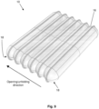
- the personal protection device includes a mattress body including a plurality of inflatable elements arranged adjacent in sequence, wherein each inflatable element has an elongated envelope - preferably substantially tubular - shape so as to define an internal chamber which is channel-like, namely shaped in the manner of a channel.
- the mattress body is designed to assume a first rest configuration in which the inflatable elements are in a deflated condition close to or stacked on top of each other.
- the mattress body is designed to assume also an active configuration in which said inflatable elements are in an inflated condition.
- the form of the mattress body which, as mentioned, is formed overall by a plurality of tubular elements arranged adjacent in sequence, favours unfolding from the stacked condition into the inflated condition where they are extended and unfolded.
- Each inflatable element has an elongated, preferably tubular, form and therefore the internal channel-shaped chamber, when the inflatable element is substantially inflated, has a form corresponding to the internal hollow zone of a tubular element.
- the tubular elements are in fact narrow and long separate bodies which are joined together in sequence side-by-side. More particularly, they consist of elements which are straight in the inflated condition, namely have a straight and/or rectilinear - and not curved - form. In this way, the tubular elements may easily pass from a compact stacked condition into an extended or unfolded condition in which the inflatable elements are fully expanded so as to obtain the flat-shaped mattress body, with an inflated panel-like configuration.
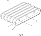
- each inflatable element has mutual connection zones and separation zones.
- the mutual connection zones are configured to maintain a mutual connection between the adjacent inflatable elements, while the separation zones are configured to maintain a separation between adjacent inflatable elements.
- the separation zones defines a plurality of through-channels passing between adjacent inflatable elements.
- the protection device also includes a covering sleeve or simple cover, which defines an internal zone where the mattress body is housed.
- the set of inflatable elements is therefore lined with at least one cover, or covering sleeve, configured to provide the airbag with greater dimensional stability and therefore resistance to high pressures.
- it may provide greater abrasion resistance and therefore, for example, may be made of a material such as a synthetic fabric, for example Cordura, but may also be made of a material with fireproof/flame-proof properties so as to ensure greater fire resistance.
- it may be formed by a pair of sheets arranged opposite each other and joined together along a respective perimeter or may be a single body.
- the covering sleeve therefore defines an internal zone or region where the mattress body including the plurality of inflatable elements is arranged.
- the device furthermore includes one or more tie elements connected to the covering sleeve and each slidably and/or freely inserted inside a respective through-channel.
- each tie element is not fixed directly to the inflatable elements, but surrounds the outer sleeve so as to help provide the flat form of the mattress body and give the entire device a greater dimensional stability and consequently resistance to high pressures. Owing to the sliding and free insertion inside the respective through-channel, the tie element may adjust the form of the protection device, without however directly acting on the inflatable elements so as to avoid excessive tensioning of the inflatable elements.
- the mutual connection zones are adherence areas.
- the inflatable elements therefore have side walls adhering in pairs and two opposite walls which, once the inflatable elements are joined together, form opposite external surfaces of the mattress body, namely a surface or wall exposed to an impact or to the cold and a rear wall facing the user.
- the two opposite surfaces are substantially flat in the inflated condition.
- the tie elements protrude from the opposite surfaces and are connected to the cover.
- the inflatable element may be easily combined with other protection devices or elements, for example rigid plate-type protection bodies, separate from the inflatable element and having a form matching that of the inflatable element in the inflated condition, or inserted inside the pocket of the wearable article.
- other protection devices or elements for example rigid plate-type protection bodies, separate from the inflatable element and having a form matching that of the inflatable element in the inflated condition, or inserted inside the pocket of the wearable article.
- a further advantage consists in the fact that the tie elements and the partially adhering walls of the inflatable elements ensure a limited expansion of the inflatable element in an inflated condition so as to obtain a smaller overall size, and in particular a limited thickness, while at the same time ensuring adequate protection for a user.
- a wearable article such as a garment, a jacket, a suit or other article of clothing.
- This smaller size moreover ensures, in the event of accidental inflation of the inflatable element, less inconvenience and risk for a user while driving a vehicle. In other words, a limited expansion of the inflatable element does not adversely affect control of a vehicle by the user and therefore does not pose the risk of an accident.
- Another advantage consists in the fact that, by controlling the form of the inflatable element. it is possible to control (and in particular limit) also the amount of gas needed for inflation of the inflatable element.
- the inflatable mattress body is therefore a flexible body which, in the inflated condition, maintains this condition at least for a given time period.
- it consists of a body which is impermeable to an inflation gas.
- a breather valve is provided for deflation of the mattress body.
- a body made of a pressure-resistant material which is able to ensure the gas-tightness for at least a certain period of time, may be used as the material for the mattress body.
- Said material may be, for example, PU (polyurethane), EVA (ethylene vinyl acetate) or TPE (thermoplastic elastomer).
- PU polyurethane
- EVA ethylene vinyl acetate
- TPE thermoplastic elastomer
- These membranes may also be impregnated with non-extensible fine meshes in order to ensure greater tightness of the inflatable elements (in terms of expansion resistance).
- a wall of an inflatable element of the plurality of inflatable elements is fixed so as to adhere only locally to a wall of an adjacent inflatable element of the plurality of inflatable elements, so as to define a mutual connection zone between two adjacent inflatable elements.
- each inflatable element, or part of them includes at least two walls which are joined together along a perimeter so as to define a perimetral joining edge.
- said adherence zone between two adjacent inflatable elements alternates with a perimetral joining edge of the two inflatable element walls.
- the inflatable element is in fact a double-leaf body, namely similar to a body with two flat sheets joined together along the perimeter so as form a long and narrow body. It can be understood that the prechosen geometrical form of an inflatable element with a double leaf joined together along the perimetral edge favours the compression of one wall against another one in the deflated condition like a concertina and at the same time the opening into the inflated condition again in the manner of a concertina.
- the protection device preferably also includes one or more gas sources connected to the inflatable mattress body so as to inflate the mattress body between the deflated condition and the inflated condition.
- the gas source may be housed inside the internal channel-like chamber of an inflatable element.
- the gas source may be a pressurised gas generator or a manual inflation device which can be activated by a user, such as an air pump.
- the inflatable elements may each have independent access to one or more gas sources.
- the adjacent inflatable elements are in fluid communication with each other for common inflation.
- the mattress body includes through-holes or fluid communication holes in the adhering walls of two said adjacent inflatable elements so as to provide the fluid communication.
- an inflation device comprising a fluid generator may be arranged outside the inflatable elements and connected there in fluid communication by means of a suitable connection.
- the protection device can be housed in a receiving area of the garment or in a garment portion.
- Said portion is understood as being a garment portion which covers a part of the body, such as the torso (neck region, chest region, shoulder joint region, back and arms).
- the garment portion includes said layer and is made using a predefined textile technology able to provide the garment with given properties, such as breathability, or with ventilation openings.
- wearable article is understood as meaning any article or portion thereof which may be worn by a user, such as an article of clothing, a garment or other wearable accessory.
- the wearable article includes a protection device such as that described above and at least one layer defining a zone for receiving the body of a user, i.e. intended to receive the body of a user for a protective function, whether it be protection from impacts or protection from the cold or the like.
- the protection device is associated with said layer, on one side, which may be identified as the inner layer of said layer, facing said receiving area.
- the layer of the wearable article also has a breathability property or has at least one ventilation opening.
- the receiving area includes a first part and a second part open towards the first part, and the breathability property or ventilation opening is associated at least with said second part of the receiving area so as to allow ventilation at least in said second part.
- the mattress body performs its protection function in the inflated condition, while ventilation and breathability may be ensured when the mattress body is in the deflated condition.
- the second part of the receiving area is configured to receive the mattress body in the extended and inflated condition, while it remains free to allow breathability when the mattress body is in the rest configuration.
- the mattress body occupies both said first part of the receiving area and said second part of the receiving area and preferably the whole of the second part of the receiving area.
- the mattress body occupies only the first part of the receiving area. Consequently, once housed inside the garment and the mattress body is in the deflated condition, the second part of the receiving area, which is normally devoid of mattress body, is able to allow the breathability and ventilation of the garment.
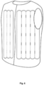
- the reference number 100 indicates a wearable article, in the present case a waistcoat, including a personal protection device 10 according to the present disclosure in accordance with a respective embodiment of the present disclosure.
- a portion of the wearable article 100 for example the chest portion, or back portion, according to the present disclosure includes at least one layer 11 defining an area for receiving the body of a user.
- the layer is a layer of the waistcoat or a lining of the waistcoat.
- the layer 11 is to be understood as being a layer of the waistcoat, in general, made of fabric or other material. Preferably, as will be explained more clearly below, at least part of the layer 11 allows breathability and the entry of air inside the wearable article 100.
- the waistcoat or similar wearable article 100 includes an area - indicated by means of broken lines and the reference number 12 - which is intended to receive the body of a user for a protection function, whether it be protection from impacts, protection from the cold, or any other kind of protection.
- the receiving area 12 is, in the embodiment shown, an area intended to receive the torso of a user.
- the layer 11 also has, as mentioned, a breathability property or has at least one ventilation opening 15.
- the protection device 10 is associated with said layer 11, on an inner side of said layer towards the receiving area, as shown in Figures 7 and 8 .
- the personal protection device 10 includes a mattress body 16, including a plurality of inflatable elements 18, arranged adjacent in sequence, wherein each inflatable element has the form of a long and narrow envelope, preferably tubular shaped, i.e. in the form of a closed tube, so as to each define an internal chamber 19 shaped like a channel.
- the inflatable elements 18 and the respective internal chambers 19 are preferably in fluid communication by means of through-holes so as to form a single inflation chamber for said inflatable elements 18.
- the inflatable elements 18 which form the mattress body 16 are identical to each other in terms of shape and size, namely they all have the same form and the same dimensions.
- the inflatable elements 19 may have a different shape and/or size, for example at least one of the inflatable elements 18 may have dimensions greater than or smaller than other inflatable elements 18 of the mattress body 16, or may be shaped differently from other inflatable elements 18 of the mattress body 16.
- the inflatable elements 18 may be organized or grouped together in groups of inflatable elements, wherein each group of inflatable elements may comprise, or group together, inflatable elements 18 with the same shape and/or size.
- the inflatable elements 18 may be grouped together in at least two groups in which the inflatable elements of each group have dimensions greater than or smaller than those of the inflatable elements of another group.
- the tubular-shaped elements 18 of one group may have a height and/or diameter greater or smaller than the inflatable elements 18 of another group.
- Each group of inflatable elements may also be arranged alongside and/or associated with a further group of inflatable elements.
- a first group of inflatable elements with a first shape and/or size may be associated with or arranged alongside a second group of inflatable elements, wherein the second group of inflatable elements comprises inflatable elements with a second shape and/or size, wherein preferably the second shape and/or size is different from the first shape and/or size.
- each inflatable element 18 has at last one mutual connection zone 20 and at least one separation zone 21.
- the mutual connection zones are configured to maintain a mutual connection, namely one where they are joined together and preferably totally adherent, between the adjacent inflatable elements 18, while the separation zones 21 are configured to maintain a separation between adjacent inflatable elements 18. Consequently, the separation zones 21 define a plurality of through-channels 28 passing between adjacent inflatable elements 18.
- the adjacent inflatable elements 18 have mutual connection zones 20 where the adjacent inflatable elements 18 are connected for example by means of gluing together, stitching or similar joining systems, and separation zones 21, where the adjacent inflatable elements 18 are kept separate and/or disconnected.
- at least one through-channel 28 is defined in each of the separation zones 21, so as to define a plurality of through-channels 28 between adjacent inflatable elements 28.
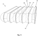
- the set of inflatable elements 18 is also covered by at least one or more membranes or a sheet designed to form a cover 50 or a covering sleeve and provide the mattress body 16 with greater dimensional stability and hence resistance to high pressures.
- the protection device 10 includes a cover 50 which defines an internal zone and said internal zone receives the mattress body 16.
- the device furthermore includes one or more tie elements 52 connected to the cover 50 or covering sleeve and each slidably and/or freely inserted inside a respective through-channel 28 between the inflatable elements 18.
- the one or more tie elements 52 surround(s) the cover 50 and is free to slide with respect to the inflatable elements 18 so as to allow form control (since it is fixed to the cover 50) but without creating a tension on the inflatable elements 18.
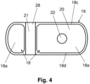
- each of the inflatable elements 18 has ta least one side wall 18a, 18b partially adhering to an adjacent side wall 18a, 18b of an adjacent inflatable element and two opposite walls 18c, 18d which, once the sequence of inflatable elements 18 has been defined, form opposite external surfaces, namely a surface or wall exposed to an impact, or to the cold, and a rear wall facing the user.
- the tie elements 52 protrude from the external surface and are connected to the cover 50.
- adherent side walls 18a, 18b of adjacent inflatable elements comprise the mutual connection zones 20, and the separation zones 21, together with the tie elements 52, help to act as components for controlling the form of the protection device 10 between the two external surfaces and to provide control of the mattress or flat form for the mattress body, without creating excessive tension on the tie elements.
- the one or more tie elements 52 are parts of an elongated body such as, for example, a band. Namely a plurality of tie elements 52 are connected together to form an elongated body 53 which, in the outer zones, may also surround the cover 50 on the outside in the manner of a hoop.
- the tie elements 52 are inserted slidably and freely inside the respective through-channels 28 and are also part of an elongated body which may surround on the outside at least partially each of the inflatable elements 18.
- the elongated body 53 may maintain and/or stabilize a desired shape of the inflatable elements 18 in the inflated condition, owing to the fact that it surrounds and encircles the tie elements.
- the inflatable elements have through-channels 28 which are aligned and the elongated body 53 is inserted slidably and/or freely inside aligned through-channels 28 between adjacent inflatable elements 18.
- the inflatable elements 18 have through-channels 28 aligned with each other in rows.
- the elongated body 53 is slidably inserted in a sinusoidal manner from above and from below the group of inflatable elements inside the respective aligned through-channels 28.
- the elongated body portions 53 which are inserted inside the through-channels 28 act as or form the tie element 52.
- the elongated body 53 which forms the tie elements 52 of a series of aligned channels 52 is inserted in a sinusoidal manner in the through-channels 28, namely, once inside the aligned through-channels 28, it may form a sinusoid which surrounds at least partially the inflatable elements 18 on the outside.
- the elongated body 53 has a plurality of connecting elements 52a configured to be associated with each other in a removable manner so as keep the internal band portions in positions corresponding to the one or more tie elements 52 inserted inside said through-channels 28, without the risk of them sliding out.
- the connecting elements 52a may be loops or annular elements which are associated with the one or more tie elements 52 and which may be connected together removably, for example, by means of one or more clasps or hooks 55 or any element suitable for keeping at least two loops or two annular elements joined together.
- the connecting elements 52a may removably connect the one or more tie elements 52 so as to prevent the tie elements 52 from coming out of the respective through-channels 28.
- this configuration not only prevents a fixed connection between the tie elements 52 and the inflatable elements 18, but also avoids having to associate the one or more tie elements 52 with the covering sleeve at too many points, for example by means of stitches, which may be difficult to execute owing to the proximity to the inflatable elements 18.
- a single stitch along the elongated body 53 may be provided, or no stitches and only hooks, fasteners or other locking devices are present.
- the mattress body 16 is designed to assume a first rest configuration in which the inflatable elements 18 are in a deflated condition close to or stacked on top of each other as shown in Figure 7 inside a first part 12a of the receiving area 12 underneath said layer 11, leaving free a second part 12b of the receiving area which is open towards the first part.
- the mattress body 16 is also designed to assume an active configuration in which said inflatable elements 18 are in an inflated condition and occupy both said first part 12a of the receiving area and the second part 12b of said receiving area 12.
- said at least one layer 11 has said breathability property or said ventilation opening 15 at least in said second part 12b of the receiving area 12, and said second part of the receiving area, when the mattress body 1 is in the deflated configuration, is devoid of the mattress body 16.
- the second part 12b of the receiving area 12 is configured to receive the protection device in the extended and inflated condition, while it remains free to allow breathability when the protection device 10 is in the deflated rest configuration.
- the mattress body 16, which overall is formed by a plurality of tubular elements 18 arranged adjacent in sequence, favours the unfolding from the stacked condition, into the extended and unfolded condition. As shown in Figure 8 , in the inflated condition, the mattress body occupies preferably the whole of the second part 12b of the receiving area.
- each inflatable element 18 has a tubular shape and therefore the internal chamber 19, when the inflatable element is substantially inflated, has a channel-like shape corresponding to the empty volume of a tubular element.
- the tubular elements 18 are in fact narrow and long. As can be seen, they are elements which are straight and not curved; in this way, not only when they are extended, the mattress body 16 has a flat shape, but they may also pass easily from a compact stacked condition into an extended condition.
- the inflatable elements 18 therefore have side walls 18a, 18b adhering to each other in pairs and two opposite walls18c, 18d which, once the inflatable elements 18 are joined together, form and act as opposite external surfaces, i.e. a surface or wall exposed to an impact or to the cold and a rear wall facing the user.
- the adjacent side walls 18a, 18b adhering to each other act as tensioning components between the two external surfaces, so as to provide control of the mattress or flat form of the mattress body.
- the mattress body 16 is inflated preferably so as to tension the side walls 18a, 18b which adhere to each other.
- the maximum tension of the tie components determines the maximum distance which is possible between the external surfaces.
- the geometry of the parts described above enables a structure which is as flat as possible to be obtained, and the inflatable elements 18 are arranged alongside each other and at the same time define, by means of the adherent walls 18a, 1b, internal separating walls or partitions suitably arranged so as to create a plurality of housings.
- the mattress body 16 includes through-holes 22 or fluid communication holes in the adherent walls 18a, 18b of two said adjacent inflatable elements, so as to form the fluid communication.
- the holes 22 are formed in the mutual connection zones 20 of the tubular elements 18.
- each inflatable element 18 includes at least two sheets 28, 29 or walls which are joined together along a perimeter so as to define a perimetral joining edge 30, defining for each inflatable element the aforementioned internal chamber 19 in fluid communication with an adjacent internal chamber.
- an adherence area 31 alternates with a perimetral joining edge 30 of the two walls 28, 29 of the inflatable element.
- the inflatable element 18 is in fact therefore a body of the double-leaf type, i.e. it is like a body having two flat sheets which are joined along the perimeter and which form a long and narrow body.
- the joining together of the two walls or sheets 28, 29 may be performed using technology known in the sector, for example by means of gluing and/or by means of suitable edging with tape or by means of spot gluing or gluing along one edge, or by means of hot pressing.
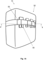
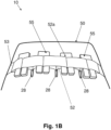
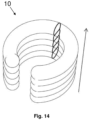
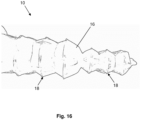
- the protection device 10 may find an application in numerous areas, also for protection of the head.
- the protection device 10 such as that described above, may be curved so as form a kind of "C" or open ring, in order to protect the head.
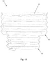
- Figure 14 shows a direction of expansion of the protection device 10, from a deflated condition, in which the inflatable elements are collapsed onto each other, and an inflated condition, in which the inflatable elements are extended so as to create a protection mattress, as described above.
- the protection device 10 may be housed in the collar of an article of clothing, in a backpack or other housing seat and extend upwards so as to protect the head when required.
- the protection device preferably includes also a gas source (not shown) connected to the inflatable mattress body so as to inflate the mattress body 16 between the deflated condition and the inflated condition.
- the gas source may be housed inside an inflatable element.
- the protection device 10 in order to perform inflation of the mattress body, in the event of a sudden fall and/or sliding and/or an impact involving a user or a vehicle being ridden/driven by the user, the protection device 10 is designed to cooperate with special activation means (not shown) which are operationally connected for example to the gas source (as mentioned, not shown), such as a canister containing compressed cold gas, for example helium.
- the canister may be provided with a respective shut-off valve (not shown).
- the inflation fluid source may comprise gas generators preferably of the pyrotechnic or hybrid type or other types known according to the state of the art. Opening of the shut-off valve of each inflation canister is preferably controlled by a control unit depending on the detection of the state of the vehicle/rider system; for example said control unit may implement a system for predicting the fall which allows early identification of the fall event and a reliable prediction of this event by means of accelerometer sensors fixed to the vehicle (or rider) and a unit for processing the signals produced by the said sensors.
- the device according to the present disclosure may also be applied using an activation cable connected to a vehicle ridden/driven by a user, which cable activates inflation of the inflatable element following the movement of the user away from the vehicle, for example following a fall or a sudden impact.
- an activation cable connected to a vehicle ridden/driven by a user, which cable activates inflation of the inflatable element following the movement of the user away from the vehicle, for example following a fall or a sudden impact.
- Use of a cable is employed in particular in the horse-riding sector.
- activation and inflation means may be incorporated in the protection device according to the present invention or located on the outside thereof.
Landscapes
- Health & Medical Sciences (AREA)
- General Health & Medical Sciences (AREA)
- Physical Education & Sports Medicine (AREA)
- Engineering & Computer Science (AREA)
- Textile Engineering (AREA)
- Professional, Industrial, Or Sporting Protective Garments (AREA)
- Mattresses And Other Support Structures For Chairs And Beds (AREA)
Claims (14)
- Schutzvorrichtung (10) für den persönlichen Schutz eines Benutzers, wobei die Vorrichtung einen Matratzenkörper (16) einschließt, der eine Vielzahl von aufblasbaren Elementen (18) einschließt, die nebeneinander in einer Reihe angeordnet sind, wobei jedes aufblasbare Element (18) eine längliche Hüllenform aufweist, so dass jedes eine innere Kammer (19) definiert, die wie ein Kanal geformt ist, und wobei der Matratzenkörper (16) so ausgelegt ist, dass er eine erste Ruhekonfiguration annimmt, in der die aufblasbaren Elemente (18) in einem entleerten Zustand nahe beieinander oder übereinander gestapelt sind, und wobei der Matratzenkörper (16) so gestaltet ist, dass er eine aktive Konfiguration annimmt, in der sich die aufblasbaren Elemente (18) in einem aufgeblasenen Zustand mit einer geraden und/oder geradlinigen Form befinden, wobei jedes aufblasbare Element (18) mindestens eine gegenseitige Verbindungszone (20) und mindestens eine Trennzone (21) aufweist, wobei die gegenseitigen Verbindungszonen (20) konfiguriert sind, um eine gegenseitige Verbindung zwischen benachbarten aufblasbaren Elementen (18) aufrechtzuerhalten, und die Trennzonen (21) konfiguriert sind, um eine Trennung zwischen benachbarten aufblasbaren Elementen (18) aufrechtzuerhalten, und wobei die Trennzonen (21) eine Vielzahl von Durchgangskanälen (28) definieren, die zwischen benachbarten aufblasbaren Elementen (18) verlaufen,und wobei die Schutzvorrichtung (10) eine Abdeckung (50) umfasst, die eine innere Zone definiert, wobei die innere Zone so konfiguriert ist, dass sie den Matratzenkörper (16) aufnimmt,und wobei die Vorrichtung ein oder mehrere Bindeelemente (52) einschließt, die mit der Abdeckung (50) verbunden sind und jeweils verschiebbar und/oder frei in einen jeweiligen Durchgangskanal (28) eingesetzt sind, der zwischen benachbarten aufblasbaren Elementen (18) verläuft,und wobei jedes der aufblasbaren Elemente (18) mindestens eine Seitenwand (18a, 18b), die teilweise an einer Seitenwand (18a, 18b) eines benachbarten aufblasbaren Elements haftet, sowie zwei gegenüberliegende Wände (18c, 18d) aufweist, die, sobald die Abfolge der aufblasbaren Elemente (18) festgelegt ist, gegenüberliegende Außenoberflächen bilden, nämlich eine Oberfläche oder Wand, die einem Aufprall oder der Kälte ausgesetzt ist, und eine dem Benutzer zugewandte Rückwand,und wobei die teilweise aneinander haftenden Seitenwände (18a, 18b) benachbarter aufblasbarer Elemente die gegenseitigen Verbindungszonen (20) und die Trennzonen (21) umfassen und die ein oder mehreren Bindeelemente (52) von gegenüberliegenden Seiten über die beiden Außenflächen hinausragen und mit der Abdeckung (50) verbunden sind.
- Schutzvorrichtung (10) nach dem vorstehenden Anspruch, wobei das eine oder die mehreren Bindeelemente (52) Teile eines länglichen Körpers (53) sind.
- Schutzvorrichtung (10) nach einem der vorstehenden Ansprüche, wobei die Bindeelemente (52) Teil eines länglichen Körpers (53) sind, der in einer sinusförmigen Anordnung in jeweilige Durchgangskanäle (28) eingesetzt ist, die zwischen benachbarten aufblasbaren Elementen (18) verlaufen.
- Schutzvorrichtung (10) nach dem vorstehenden Anspruch, wobei ein Teil des einzelnen länglichen Körpers (53), der aus der Abdeckung (50) hervorsteht, entsprechende Verbindungselemente (52a) aufweist, die konfiguriert sind, um einander in einer entfernbaren Weise zugeordnet zu werden, so dass die verbleibenden Abschnitte des länglichen Körpers, die die Bindeelemente (52) bilden, innerhalb der Durchgangskanäle (28) eingesetzt bleiben.
- Schutzvorrichtung (10) nach dem vorstehenden Anspruch, wobei die Verbindungselemente (52a) mittels eines oder mehrerer Spangen- oder Hakenelemente (55) in einer entfernbaren Weise einander zugeordnet sind.
- Schutzvorrichtung (10) nach Anspruch 3, 4 oder 5, wobei ein Teil des einzelnen länglichen Körpers (53) außerhalb der Abdeckung liegt und die Abdeckung (50) umschließt oder umgibt.
- Schutzvorrichtung nach Anspruch 3, wobei eine Vielzahl der benachbarten aufblasbaren Elemente (18) Durchgangskanäle (28) aufweisen, die in Reihen zueinander ausgerichtet sind, und der längliche Körper (53) in sinusförmiger Weise von oben und von unten in die Abfolge der aufblasbaren Elemente (18) in die jeweiligen Durchgangskanäle gleitend eingesetzt ist, die so ausgerichtet sind, dass sie eine Sinuskurve bilden, die die aufblasbaren Elemente (18) außen zumindest teilweise umgibt, und wobei die Schutzvorrichtung Verbindungselemente (52a) zum Zusammenfügen benachbarter Abschnitte des länglichen Körpers (53) umfasst, die aus den jeweiligen Durchgangskanälen (28) hervorstehen, die zwischen benachbarten aufblasbaren Elementen (18) verlaufen.
- Schutzvorrichtung (10) nach einem der vorstehenden Ansprüche, wobei die aufblasbaren Elemente (18) und die jeweiligen Innenkammern (19) in Fluidverbindung stehen, um eine einzige Aufblaskammer für die aufblasbaren Elemente (18) auszubilden.
- Schutzvorrichtung (10) nach einem der vorstehenden Ansprüche, wobei der Matratzenkörper (16) Durchgangslöcher (22) oder Fluidverbindungslöcher in den aneinander haftenden Wänden (18a, 18b) zweier benachbarter aufblasbarer Elemente aufweist, um die Fluidverbindung herzustellen.
- Schutzvorrichtung (10) nach einem der vorstehenden Ansprüche, wobei jedes aufblasbare Element (18) oder jeder Teil der aufblasbaren Elemente mindestens zwei Wände oder Platten (28, 29) umfasst, die entlang eines Umfangs miteinander verbunden sind, um eine umlaufende Verbindungskante (30) zu definieren, und wobei entlang der Abfolge benachbarter aufblasbarer Elemente (18) ein Haftbereich (31) mit einer umlaufenden Verbindungskante (30) der beiden Wände (28, 29) des aufblasbaren Elements (18) abwechselt, und wobei die gegenüberliegenden Wände (18c, 18d) die umlaufende Verbindungskante (30) umfassen, und wobei die teilweise haftenden Seitenwände (18a, 18b) den Haftbereich (31) umfassen.
- Schutzvorrichtung (10) nach einem der vorstehenden Ansprüche, wobei die Schutzvorrichtung eine Aufprallschutzvorrichtung ist einschließlich einer Druckgasquelle, wobei die Schutzvorrichtung konfiguriert ist, um im Falle einer Gefahr oder eines Aufpralls den zweiten aktiven aufgeblasenen Zustand zu bestimmen.
- Schutzvorrichtung (10) nach einem der vorstehenden Ansprüche 1 bis 10, wobei die Schutzvorrichtung eine Kälteschutzvorrichtung ist, einschließlich einer Druckgasquelle, wobei die Schutzvorrichtung konfiguriert ist, um den aufgeblasenen Zustand zum Schutz eines Benutzers vor der Kälte zu bestimmen.
- Tragbarer Artikel (100) einschließlich einer Schutzvorrichtung (10) nach einem der vorangehenden Ansprüche.
- Tragbarer Artikel (100) nach dem vorstehenden Anspruch, der mindestens eine Schicht (11) einschließt, die zumindest teilweise einen Aufnahmebereich (12) zum Aufnehmen des Körpers eines Benutzers definiert, wobei die Schicht (11) eine Atmungsaktivitätseigenschaft und/oder mindestens eine Belüftungsöffnung (15) aufweist und wobei die Schutzvorrichtung (10) mit der Schicht (11) auf einer Seite der Schicht in Richtung des Aufnahmebereichs (12) verbunden ist, und wobei der Aufnahmebereich (12) einen ersten Teil (12a) und einen zweiten Teil (12b) umfasst, der zum ersten Teil (12a) hin offen ist, und wobei die Atmungsaktivitätseigenschaft und/oder mindestens eine Belüftungsöffnung (15) mindestens dem zweiten Teil (12b) zugeordnet ist/sind; und wobei die aufblasbaren Elemente in dem ersten entleerten Zustand den ersten Teil (12a) des Aufnahmebereichs (12) unterhalb der Schicht (11) einnehmen und in dem aufgeblasenen Zustand den ersten Teil (12a) des Aufnahmebereichs und den zweiten Teil (12b) des Aufnahmebereichs (12) einnehmen, und wobei eine Situation, in der der zweite Teil (12b) des Aufnahmebereichs (12) frei von dem Matratzenkörper (16) ist, einer Situation entspricht, in der der Matratzenkörper (16) in dem entleerten Zustand ist.
Applications Claiming Priority (1)
| Application Number | Priority Date | Filing Date | Title |
|---|---|---|---|
| IT102022000010424A IT202200010424A1 (it) | 2022-05-19 | 2022-05-19 | Dispositivo di protezione personale |
Publications (3)
| Publication Number | Publication Date |
|---|---|
| EP4278917A1 EP4278917A1 (de) | 2023-11-22 |
| EP4278917B1 true EP4278917B1 (de) | 2025-03-05 |
| EP4278917C0 EP4278917C0 (de) | 2025-03-05 |
Family
ID=82943260
Family Applications (1)
| Application Number | Title | Priority Date | Filing Date |
|---|---|---|---|
| EP23174182.8A Active EP4278917B1 (de) | 2022-05-19 | 2023-05-18 | Persönliche schutzvorrichtung |
Country Status (3)
| Country | Link |
|---|---|
| EP (1) | EP4278917B1 (de) |
| ES (1) | ES3032640T3 (de) |
| IT (1) | IT202200010424A1 (de) |
Citations (9)
| Publication number | Priority date | Publication date | Assignee | Title |
|---|---|---|---|---|
| WO1995015706A1 (en) | 1993-12-06 | 1995-06-15 | Talley Group Limited | Inflatable mattresses |
| US6176515B1 (en) | 1999-10-07 | 2001-01-23 | Trw Vehicle Safety Systems Inc. | Inflatable curtain with positioning device |
| EP2621297B1 (de) | 2010-09-29 | 2017-08-09 | Hövding Sverige AB | Kopfschutz-airbag |
| EP3434123A1 (de) | 2017-07-25 | 2019-01-30 | Dainese S.p.A. | Schutzvorrichtung |
| EP3498117A1 (de) | 2017-12-18 | 2019-06-19 | Dainese S.p.A. | Kleidungsstück zum schutz eines benutzers mit einem aufblasbaren element |
| WO2021116931A1 (en) | 2019-12-13 | 2021-06-17 | D-Air Lab S.r.l. | Protective device and method for making said protective device |
| GB2590811A (en) | 2020-12-23 | 2021-07-07 | Airhead Design Ltd | Inflatable helmet |
| WO2021260002A1 (en) | 2020-06-26 | 2021-12-30 | Alpinestars Research S.p.A. | Wearable protection device |
| EP4197378A1 (de) | 2021-12-20 | 2023-06-21 | D-Air Lab S.r.l. | Persönliche schutzausrüstung |
Family Cites Families (4)
| Publication number | Priority date | Publication date | Assignee | Title |
|---|---|---|---|---|
| US3319260A (en) * | 1964-06-10 | 1967-05-16 | Gen Dynamics Corp | Survival garment |
| EP1767108A1 (de) * | 2005-09-21 | 2007-03-28 | Hajdar Ademaj | Aufblasbares Schutzkleidungsstück |
| JP5486607B2 (ja) | 2008-12-09 | 2014-05-07 | ダイネーゼ ソシエタ ペル アチオーニ | 膨張可能部材を含む保護デバイス |
| ITVR20150074A1 (it) | 2015-05-06 | 2016-11-06 | Dainese Spa | Dispositivo di protezione e metodo per realizzare tale dispositivo di protezione |
-
2022
- 2022-05-19 IT IT102022000010424A patent/IT202200010424A1/it unknown
-
2023
- 2023-05-18 ES ES23174182T patent/ES3032640T3/es active Active
- 2023-05-18 EP EP23174182.8A patent/EP4278917B1/de active Active
Patent Citations (9)
| Publication number | Priority date | Publication date | Assignee | Title |
|---|---|---|---|---|
| WO1995015706A1 (en) | 1993-12-06 | 1995-06-15 | Talley Group Limited | Inflatable mattresses |
| US6176515B1 (en) | 1999-10-07 | 2001-01-23 | Trw Vehicle Safety Systems Inc. | Inflatable curtain with positioning device |
| EP2621297B1 (de) | 2010-09-29 | 2017-08-09 | Hövding Sverige AB | Kopfschutz-airbag |
| EP3434123A1 (de) | 2017-07-25 | 2019-01-30 | Dainese S.p.A. | Schutzvorrichtung |
| EP3498117A1 (de) | 2017-12-18 | 2019-06-19 | Dainese S.p.A. | Kleidungsstück zum schutz eines benutzers mit einem aufblasbaren element |
| WO2021116931A1 (en) | 2019-12-13 | 2021-06-17 | D-Air Lab S.r.l. | Protective device and method for making said protective device |
| WO2021260002A1 (en) | 2020-06-26 | 2021-12-30 | Alpinestars Research S.p.A. | Wearable protection device |
| GB2590811A (en) | 2020-12-23 | 2021-07-07 | Airhead Design Ltd | Inflatable helmet |
| EP4197378A1 (de) | 2021-12-20 | 2023-06-21 | D-Air Lab S.r.l. | Persönliche schutzausrüstung |
Also Published As
| Publication number | Publication date |
|---|---|
| ES3032640T3 (en) | 2025-07-22 |
| EP4278917A1 (de) | 2023-11-22 |
| EP4278917C0 (de) | 2025-03-05 |
| IT202200010424A1 (it) | 2023-11-19 |
Similar Documents
| Publication | Publication Date | Title |
|---|---|---|
| CN113194772B (zh) | 可穿着的气袋装置 | |
| US12012065B2 (en) | Protective device and method for making said protective device | |
| EP4197378B1 (de) | Persönliche schutzausrüstung | |
| EP3918935A1 (de) | Kleidungsstück zum schutz eines benutzers mit einem aufblasbaren element | |
| EP3167730B1 (de) | Tragbare schutzvorrichtung | |
| JP2023531261A (ja) | 装着型保護装置 | |
| US8998667B2 (en) | Personal floatation device having selectively inflatable bladders | |
| EP3434123B1 (de) | Schutzvorrichtung | |
| US6678895B1 (en) | Protective garment, which is worn with shoulder pad having inflatable bladder, for firefighter or for emergency worker | |
| EP3795020B1 (de) | Schutzvorrichtung und verfahren zur herstellung dieser schutzvorrichtung | |
| EP4278917B1 (de) | Persönliche schutzvorrichtung | |
| WO2013126705A1 (en) | Personal flotation device having selectively inflatable bladders | |
| EP3835140B1 (de) | Schutzvorrichtung und verfahren zur herstellung dieser schutzvorrichtung | |
| EP4029396B1 (de) | Kopfschutzgerät | |
| US20260000135A1 (en) | Protection device for the neck, process of making the same, garment comprising said protection device | |
| JP7472841B2 (ja) | 着用エアバッグ装置 | |
| WO2018197718A1 (en) | Lifejacket | |
| KR20250106730A (ko) | 팽창 가능 보호 디바이스, 이러한 팽창 가능 보호 디바이스를 포함하는 웨어러블 보호 디바이스 및 팽창 후 이러한 팽창 가능 보호 디바이스를 효과적으로 수축시키기 위한 방법 | |
| EP4694719A1 (de) | Aufblasbare kleidungsauskleidung und zugehöriges kleidungsstück |
Legal Events
| Date | Code | Title | Description |
|---|---|---|---|
| PUAI | Public reference made under article 153(3) epc to a published international application that has entered the european phase |
Free format text: ORIGINAL CODE: 0009012 |
|
| STAA | Information on the status of an ep patent application or granted ep patent |
Free format text: STATUS: THE APPLICATION HAS BEEN PUBLISHED |
|
| AK | Designated contracting states |
Kind code of ref document: A1 Designated state(s): AL AT BE BG CH CY CZ DE DK EE ES FI FR GB GR HR HU IE IS IT LI LT LU LV MC ME MK MT NL NO PL PT RO RS SE SI SK SM TR |
|
| STAA | Information on the status of an ep patent application or granted ep patent |
Free format text: STATUS: REQUEST FOR EXAMINATION WAS MADE |
|
| 17P | Request for examination filed |
Effective date: 20240521 |
|
| RBV | Designated contracting states (corrected) |
Designated state(s): AL AT BE BG CH CY CZ DE DK EE ES FI FR GB GR HR HU IE IS IT LI LT LU LV MC ME MK MT NL NO PL PT RO RS SE SI SK SM TR |
|
| RIC1 | Information provided on ipc code assigned before grant |
Ipc: A41D 13/018 20060101AFI20240822BHEP |
|
| GRAP | Despatch of communication of intention to grant a patent |
Free format text: ORIGINAL CODE: EPIDOSNIGR1 |
|
| STAA | Information on the status of an ep patent application or granted ep patent |
Free format text: STATUS: GRANT OF PATENT IS INTENDED |
|
| INTG | Intention to grant announced |
Effective date: 20241001 |
|
| GRAS | Grant fee paid |
Free format text: ORIGINAL CODE: EPIDOSNIGR3 |
|
| GRAA | (expected) grant |
Free format text: ORIGINAL CODE: 0009210 |
|
| STAA | Information on the status of an ep patent application or granted ep patent |
Free format text: STATUS: THE PATENT HAS BEEN GRANTED |
|
| AK | Designated contracting states |
Kind code of ref document: B1 Designated state(s): AL AT BE BG CH CY CZ DE DK EE ES FI FR GB GR HR HU IE IS IT LI LT LU LV MC ME MK MT NL NO PL PT RO RS SE SI SK SM TR |
|
| REG | Reference to a national code |
Ref country code: GB Ref legal event code: FG4D |
|
| REG | Reference to a national code |
Ref country code: CH Ref legal event code: EP |
|
| REG | Reference to a national code |
Ref country code: IE Ref legal event code: FG4D |
|
| REG | Reference to a national code |
Ref country code: DE Ref legal event code: R096 Ref document number: 602023002284 Country of ref document: DE |
|
| U01 | Request for unitary effect filed |
Effective date: 20250403 |
|
| U07 | Unitary effect registered |
Designated state(s): AT BE BG DE DK EE FI FR IT LT LU LV MT NL PT RO SE SI Effective date: 20250410 |
|
| U20 | Renewal fee for the european patent with unitary effect paid |
Year of fee payment: 3 Effective date: 20250522 |
|
| PG25 | Lapsed in a contracting state [announced via postgrant information from national office to epo] |
Ref country code: RS Free format text: LAPSE BECAUSE OF FAILURE TO SUBMIT A TRANSLATION OF THE DESCRIPTION OR TO PAY THE FEE WITHIN THE PRESCRIBED TIME-LIMIT Effective date: 20250605 |
|
| PG25 | Lapsed in a contracting state [announced via postgrant information from national office to epo] |
Ref country code: NO Free format text: LAPSE BECAUSE OF FAILURE TO SUBMIT A TRANSLATION OF THE DESCRIPTION OR TO PAY THE FEE WITHIN THE PRESCRIBED TIME-LIMIT Effective date: 20250605 |
|
| PG25 | Lapsed in a contracting state [announced via postgrant information from national office to epo] |
Ref country code: HR Free format text: LAPSE BECAUSE OF FAILURE TO SUBMIT A TRANSLATION OF THE DESCRIPTION OR TO PAY THE FEE WITHIN THE PRESCRIBED TIME-LIMIT Effective date: 20250305 |
|
| PG25 | Lapsed in a contracting state [announced via postgrant information from national office to epo] |
Ref country code: GR Free format text: LAPSE BECAUSE OF FAILURE TO SUBMIT A TRANSLATION OF THE DESCRIPTION OR TO PAY THE FEE WITHIN THE PRESCRIBED TIME-LIMIT Effective date: 20250606 |
|
| REG | Reference to a national code |
Ref country code: ES Ref legal event code: FG2A Ref document number: 3032640 Country of ref document: ES Kind code of ref document: T3 Effective date: 20250722 |
|
| PG25 | Lapsed in a contracting state [announced via postgrant information from national office to epo] |
Ref country code: SM Free format text: LAPSE BECAUSE OF FAILURE TO SUBMIT A TRANSLATION OF THE DESCRIPTION OR TO PAY THE FEE WITHIN THE PRESCRIBED TIME-LIMIT Effective date: 20250305 |
|
| PGFP | Annual fee paid to national office [announced via postgrant information from national office to epo] |
Ref country code: ES Payment date: 20250630 Year of fee payment: 3 |
|
| PG25 | Lapsed in a contracting state [announced via postgrant information from national office to epo] |
Ref country code: PL Free format text: LAPSE BECAUSE OF FAILURE TO SUBMIT A TRANSLATION OF THE DESCRIPTION OR TO PAY THE FEE WITHIN THE PRESCRIBED TIME-LIMIT Effective date: 20250305 |
|
| PG25 | Lapsed in a contracting state [announced via postgrant information from national office to epo] |
Ref country code: CZ Free format text: LAPSE BECAUSE OF FAILURE TO SUBMIT A TRANSLATION OF THE DESCRIPTION OR TO PAY THE FEE WITHIN THE PRESCRIBED TIME-LIMIT Effective date: 20250305 |
|
| PG25 | Lapsed in a contracting state [announced via postgrant information from national office to epo] |
Ref country code: SK Free format text: LAPSE BECAUSE OF FAILURE TO SUBMIT A TRANSLATION OF THE DESCRIPTION OR TO PAY THE FEE WITHIN THE PRESCRIBED TIME-LIMIT Effective date: 20250305 |
|
| PG25 | Lapsed in a contracting state [announced via postgrant information from national office to epo] |
Ref country code: IS Free format text: LAPSE BECAUSE OF FAILURE TO SUBMIT A TRANSLATION OF THE DESCRIPTION OR TO PAY THE FEE WITHIN THE PRESCRIBED TIME-LIMIT Effective date: 20250705 |
|
| PLBI | Opposition filed |
Free format text: ORIGINAL CODE: 0009260 |
|
| PLAX | Notice of opposition and request to file observation + time limit sent |
Free format text: ORIGINAL CODE: EPIDOSNOBS2 |
|
| 26 | Opposition filed |
Opponent name: ALPINESTARS S.P.A. Effective date: 20251205 |
|
| PG25 | Lapsed in a contracting state [announced via postgrant information from national office to epo] |
Ref country code: MC Free format text: LAPSE BECAUSE OF FAILURE TO SUBMIT A TRANSLATION OF THE DESCRIPTION OR TO PAY THE FEE WITHIN THE PRESCRIBED TIME-LIMIT Effective date: 20250305 |