EP4278095B1 - Luftpumpenanordnung für ein aufblasbares produkt - Google Patents
Luftpumpenanordnung für ein aufblasbares produkt Download PDFInfo
- Publication number
- EP4278095B1 EP4278095B1 EP22700434.8A EP22700434A EP4278095B1 EP 4278095 B1 EP4278095 B1 EP 4278095B1 EP 22700434 A EP22700434 A EP 22700434A EP 4278095 B1 EP4278095 B1 EP 4278095B1
- Authority
- EP
- European Patent Office
- Prior art keywords
- air
- housing
- assembly
- vent
- pump housing
- Prior art date
- Legal status (The legal status is an assumption and is not a legal conclusion. Google has not performed a legal analysis and makes no representation as to the accuracy of the status listed.)
- Active
Links
Images











Classifications
-
- F—MECHANICAL ENGINEERING; LIGHTING; HEATING; WEAPONS; BLASTING
- F04—POSITIVE - DISPLACEMENT MACHINES FOR LIQUIDS; PUMPS FOR LIQUIDS OR ELASTIC FLUIDS
- F04D—NON-POSITIVE-DISPLACEMENT PUMPS
- F04D29/00—Details, component parts, or accessories
- F04D29/40—Casings; Connections of working fluid
- F04D29/42—Casings; Connections of working fluid for radial or helico-centrifugal pumps
- F04D29/4206—Casings; Connections of working fluid for radial or helico-centrifugal pumps especially adapted for elastic fluid pumps
- F04D29/4226—Fan casings
- F04D29/4253—Fan casings with axial entry and discharge
-
- F—MECHANICAL ENGINEERING; LIGHTING; HEATING; WEAPONS; BLASTING
- F04—POSITIVE - DISPLACEMENT MACHINES FOR LIQUIDS; PUMPS FOR LIQUIDS OR ELASTIC FLUIDS
- F04D—NON-POSITIVE-DISPLACEMENT PUMPS
- F04D29/00—Details, component parts, or accessories
- F04D29/40—Casings; Connections of working fluid
- F04D29/42—Casings; Connections of working fluid for radial or helico-centrifugal pumps
- F04D29/4206—Casings; Connections of working fluid for radial or helico-centrifugal pumps especially adapted for elastic fluid pumps
-
- F—MECHANICAL ENGINEERING; LIGHTING; HEATING; WEAPONS; BLASTING
- F04—POSITIVE - DISPLACEMENT MACHINES FOR LIQUIDS; PUMPS FOR LIQUIDS OR ELASTIC FLUIDS
- F04D—NON-POSITIVE-DISPLACEMENT PUMPS
- F04D25/00—Pumping installations or systems
- F04D25/02—Units comprising pumps and their driving means
- F04D25/06—Units comprising pumps and their driving means the pump being electrically driven
-
- F—MECHANICAL ENGINEERING; LIGHTING; HEATING; WEAPONS; BLASTING
- F04—POSITIVE - DISPLACEMENT MACHINES FOR LIQUIDS; PUMPS FOR LIQUIDS OR ELASTIC FLUIDS
- F04D—NON-POSITIVE-DISPLACEMENT PUMPS
- F04D25/00—Pumping installations or systems
- F04D25/02—Units comprising pumps and their driving means
- F04D25/08—Units comprising pumps and their driving means the working fluid being air, e.g. for ventilation
- F04D25/084—Units comprising pumps and their driving means the working fluid being air, e.g. for ventilation hand fans
-
- F—MECHANICAL ENGINEERING; LIGHTING; HEATING; WEAPONS; BLASTING
- F04—POSITIVE - DISPLACEMENT MACHINES FOR LIQUIDS; PUMPS FOR LIQUIDS OR ELASTIC FLUIDS
- F04D—NON-POSITIVE-DISPLACEMENT PUMPS
- F04D29/00—Details, component parts, or accessories
- F04D29/40—Casings; Connections of working fluid
- F04D29/42—Casings; Connections of working fluid for radial or helico-centrifugal pumps
- F04D29/44—Fluid-guiding means, e.g. diffusers
- F04D29/46—Fluid-guiding means, e.g. diffusers adjustable
- F04D29/50—Fluid-guiding means, e.g. diffusers adjustable for reversing fluid flow
- F04D29/503—Fluid-guiding means, e.g. diffusers adjustable for reversing fluid flow especially adapted for elastic fluid pumps
-
- F—MECHANICAL ENGINEERING; LIGHTING; HEATING; WEAPONS; BLASTING
- F04—POSITIVE - DISPLACEMENT MACHINES FOR LIQUIDS; PUMPS FOR LIQUIDS OR ELASTIC FLUIDS
- F04D—NON-POSITIVE-DISPLACEMENT PUMPS
- F04D17/00—Radial-flow pumps, e.g. centrifugal pumps; Helico-centrifugal pumps
- F04D17/08—Centrifugal pumps
- F04D17/16—Centrifugal pumps for displacing without appreciable compression
-
- F—MECHANICAL ENGINEERING; LIGHTING; HEATING; WEAPONS; BLASTING
- F04—POSITIVE - DISPLACEMENT MACHINES FOR LIQUIDS; PUMPS FOR LIQUIDS OR ELASTIC FLUIDS
- F04D—NON-POSITIVE-DISPLACEMENT PUMPS
- F04D25/00—Pumping installations or systems
- F04D25/02—Units comprising pumps and their driving means
- F04D25/06—Units comprising pumps and their driving means the pump being electrically driven
- F04D25/0673—Battery powered
-
- F—MECHANICAL ENGINEERING; LIGHTING; HEATING; WEAPONS; BLASTING
- F04—POSITIVE - DISPLACEMENT MACHINES FOR LIQUIDS; PUMPS FOR LIQUIDS OR ELASTIC FLUIDS
- F04D—NON-POSITIVE-DISPLACEMENT PUMPS
- F04D29/00—Details, component parts, or accessories
- F04D29/60—Mounting; Assembling; Disassembling
- F04D29/62—Mounting; Assembling; Disassembling of radial or helico-centrifugal pumps
- F04D29/624—Mounting; Assembling; Disassembling of radial or helico-centrifugal pumps especially adapted for elastic fluid pumps
Definitions
- the present disclosure relates to an inflatable product, in particular to an air pump assembly.
- Inflatable products can achieve their due function due to volume expansion when they are full of air, and they can be easily folded and stored or carried out when they are fully deflated.
- the inflating and deflating device matched with inflatable products comprises pumps, electric pumps, and built-in air pumps.
- the separate pumps and electric pumps are used to inflate and deflate manually, which are time-consuming and labor-intensive, inconvenient to carry, and troublesome to operate, and they are replaced by a built-in air pump.
- CN 210423098 U describes an air pump assembly for an inflatable product having an interior, comprising:a housing having a vent hole in fluid communication with the interior of the inflatable product; a cover coupled to the housing, the cover including a plurality of vent openings; and a rotatable assembly supported by the housing, the rotatable assembly comprising a pump housing having a first air vent and a second air vent; an impeller positioned in the pump housing; a motor operatively coupled to the impeller to drive a rotation of the impeller; wherein the rotatable assembly being rotatable to a first position wherein air flows from the first air vent of the pump housing to the second air vent of the pump housing and subsequently through the vent hole in the housing into the interior of the inflatable product and a second position wherein air flows from the interior of the inflatable product through the vent hole in the housing into the first air vent of the pump housing to the second air vent of the pump housing.
- the built-in air pump uses a motor to drive a blade to rotate, thereby sucking the outside air into the inflatable product.
- a closed end of the blade is on the other side of the air inlet, the air at the inlet and outlet are easily channeling, which affects the wind pressure and flow efficiency.
- an upper cover plate is provided in the traditional product, the upper cover plate is fixed to the closed blade through ultrasonic waves, glue dispensing, etc.
- the closed blade increases the sealing of the blade and improves the efficiency.
- Exemplary shortcomings include the production process is complicated, the synthesized blades are poorly balanced, and the cost is high.
- an air pump assembly for an inflatable product according to claim 1 is provided.
- Preferred embodiments are defined in dependent claims 2-15.
- the motor may maintain an orientation relative to each of the first air vent of the pump housing and the second air vent of the pump housing when the rotatable assembly is in both the first position and the second position.
- the rotatable assembly may further include a rotating handwheel which extends through an opening in the cover.
- the motor may be captured between the rotating handwheel and the pump housing.
- the rotating handwheel may maintain an orientation relative to each of the first air vent of the pump housing and the second air vent of the pump housing when the rotatable assembly is in both the first position and the second position.
- the rotary disc may include a first air vent and a second air vent.
- the first air vent of the rotary disc may communicate air to the first air vent of the pump housing when the rotatable assembly is in the first position and the first air vent of the rotary disc may receive air from the first air vent of the pump housing when the rotatable assembly is in the second position.
- the rotating handwheel may maintain an orientation relative to the rotary disc when the rotatable assembly is in both the first position and the second position.
- a sealing ring may be positioned between the rotary disc and the housing and about the vent hole in the housing.
- a pressure plate may couple the rotary disc to the housing.
- the impeller may include a circular ring cover plate having a central opening and at least one blade coupled to the circular ring cover plate.
- the impeller may further comprise a baffle extending from the circular ring cover plate in a first direction, the at least one blade extending from the circular ring cover plate in a second direction, the second direction being opposite the first direction.
- the baffle may be received in a recess in the pump housing.
- the impeller may further comprise at least one attachment blade extending from the baffle.
- the rotatable assembly may further includes a circuit board operatively coupled to the motor and a switch operatively coupled to the circuit board to control operation of the motor.
- the cover may include a control plate which cooperates with the switch to control operation of the motor.
- An air pump assembly for an inflatable product having a cover plate is moved to the air inlet of the blade, which increases the sealing of the air inlet of the blade, and the air at the inlet and outlet is not easily channeling, which improves the efficiency and the production process is simple.
- An air pump assembly for an inflatable product having a housing is provided with a USB interface or a Type-C interface for connecting an external power source. In this way, external power sources such as power bank, car cigarette lighter conversion USB connector, etc. can be used to supply power to the air pump assembly. This makes it easier for users to find an external power supply that can be used in various environments, so that the inflatable product can be used in various situations.
- An air pump assembly for an inflatable product takes into account the detachable structure of the air pump, the storage of the air pump power cord and the setting of the spare inflation interface, so that when the inflatable system is set in the inflator, the rotation of the air pump can be used to achieve multiple working modes such as inflating, stopping, and deflating.
- An accommodating cavity may be provided on the side of the fixed portion of the housing and may be used as a carrier for the air pump power cord on the one hand and may be further provided with an inflatable interface connected to the inner side of the inflatable product.
- This inflatable interface can use a manual inflator to inflate the inflatable product when the air pump is not working (such as when there is no external power supply). This makes the application scenarios of the inflatable product more diversified.
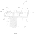
- Air pump assembly 100 includes an air pump 102 and a housing 120. Referring to FIG. 2 , air pump assembly 100 may be received in an inflatable product 10 and be accessible from an exterior of the inflatable product 10.
- Inflatable product 10 is illustratively an inflatable mattress, but may take other forms including inflatable pools, inflatable toys, and other suitable inflatable products.
- air pump 102 includes a rotatable assembly 104 and an operator actuatable input, illustratively a rotating handwheel 106.
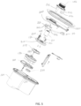
- rotating assembly 104 includes a motor 110, a pump housing 112, and an impeller 114 including at least one blade 116.
- Pump housing 112 may include an upper pump housing 130 and a lower pump housing 132 which cooperate to form a cavity 134 in which impeller 114 is positioned.
- Lower pump housing 132 includes a first air vent 136 and a second air vent 138.
- first air vent 136 is referred to as an air inlet and second air vent 138 is referred to as an air outlet. This corresponds to an inflation operation of air pump 102 and during a deflation operation first air vent 136 functions as an air outlet and second air vent 138 functions as an air inlet.
- rotating assembly 104 further includes a rotary disc 160 having a first air vent 162 and a second air vent 164.
- Rotary disc 160 includes a wall boundary 166 which cooperates with a wall boundary 156 of lower pump housing 132 to form a fluid conduit through which first air vent 136 of lower pump housing 132 is in fluid communication with first air vent 162 of rotary disc 160.
- Rotary disc 160 further includes a wall boundary 168 which cooperates with a wall boundary 158 of lower pump housing 132 to form a fluid conduit through which second air vent 138 of lower pump housing 132 is in fluid communication with second air vent 164 of rotary disc 160.
- motor 110, upper pump housing 130, lower pump housing 132, and rotary disc 160 are connected in sequence from a top side 122 of housing 120 to a bottom side 124 of housing 120.
- Motor 110 is fixed to an upper end surface 140 (see FIG. 3 ) of upper pump housing 130.
- Impeller 114 is arranged in the cavity 132 formed by upper pump housing 130 and lower pump housing 132.
- Pump lower housing 132 of pump housing 112 and the rotary disc 160 form an airway switching device, wherein pump housing 112 and the rotary disc 160 are respectively provided with air inlets 136, 162 and air outlets 138, 164.
- the airway switch device can make the air inlets 136, 162 and the air outlets 138, 164 each respectively connected to the first vent hole 200 (see FIG. 14 ) at the bottom side 124 of the housing 120 to realize the functions of inflating and deflating the air pump.
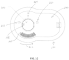
- motor 110, pump housing 112, and rotary disc 160 rotate as a unit 172 to connect either air inlets 136, 162 to first vent hole 200 of pump housing 112 in a deflation mode of air pump assembly 100 (see FIGS. 10 and 11 ) or air outlets 138, 164 to first vent hole 200 of pump housing 112 in an inflation mode of air pump assembly 100 (see FIGS. 6 and 7 ).
- unit 172 rotates about a vertical axis 170. Referring to FIGS. 7 and 11 , in the inflation mode, motor 110 is generally positioned on a left side of vertical axis 170 and in a deflation mode is generally positioned on a right side of vertical axis 170.
- rotating handwheel 106 is coupled to unit 172 to rotate with unit 172.
- rotating handwheel 106 is coupled to unit 172 through a linkage or drive mechanism, such as gears, and does not rotate as a unit with unit 172.
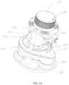
- an upper side 142 of the upper pump housing 130 is provided with a plurality of connecting columns 210 which align with a plurality of connecting columns 212 extending from a lower side 214 (see FIG. 13 ) of rotating handwheel 106.
- a top of connecting columns 210 of upper pump housing 130 are received in a lower opening in connecting columns 212 of rotating handwheel 106.
- Rotating handwheel 106 and upper pump housing 130 are fixedly connected by bolts (not shown) or other suitable fasteners.
- rotating handwheel 106 and upper pump housing 130 may further be fixedly connected by means other than a bolt connection, such as a buckle connection.
- the upper side 142 of upper pump housing 130 is further provided with a column 220.
- a switch base 222 is coupled to column 220 through an opening 224 of column 220.
- a switch 230 is connected with the switch base 222. Switch 230 controls an operation of motor 110 and thus the operation of air pump assembly 100.
- Cover 240 is received by an opening in housing 120 and is secured to housing 120.
- Cover 240 includes an opening 242 through which rotating handwheel 106 extends and a plurality of vent openings 244 through which ambient air passes through cover 240, into pump housing 112, and out through first vent hole 200 of housing 120 into an interior 12 of inflatable product 10 in an inflation mode of air pump assembly 100 and air passes from interior 12 of inflatable product 10 through first vent hole 200 in housing 120, through pump housing 112, and through cover 240 in a deflation mode of air pump assembly 100.
- Cover 240 further includes a control plate 246 extending from a lower side 248 of cover 240.
- Control plate 246 interacts with switch 230 to control the operation of motor 110.
- rotating handwheel 106 includes an indicia 108 which is generally aligned with switch 230.
- indicia 108 is aligned with an inflation indicia 260 on an upper side 249 of cover 240 and switch 230 is not depressed by control plate 246 of cover 240.
- switch 230 is not depressed, the electronic circuitry on circuit board 250 supplies electricity to motor 110 to power rotation of motor 110 and hence impeller 114.
- indica 108 comes into alignment with a sealing or off indica 264 corresponding to a sealed mode of air pump assembly 100 as shown in FIG. 8 .
- switch 230 contacts control plate 246 of cover 240 and is depressed.
- switch 230 is depressed, the electronic circuitry on circuit board 250 cuts power to motor 110.
- indica 108 comes into alignment with a deflation indica 264 corresponding to a deflation mode of air pump assembly 100 as shown in FIG. 10 .
- rotating handwheel 106 is in the position shown in FIG.
- switch 230 is not depressed by control plate 246 of cover 240 and the electronic circuitry on circuit board 250 supplies electricity to motor 110 to power rotation of motor 110 and hence impeller 114.
- rotating handwheel 106 drives upper pump housing 130 to rotate and the switch 230 to abut or separate from control plate 246 of cover 240, so that switch 230 can be opened or closed.
- the switch base 222 is further conductively connected to the circuit board 250 through two conductive pins 252, and the circuit board 250 is connected to socket 50 in cover 240 (see FIG. 2 ).
- Socket 50 may be an USB interface or a Type-C interface through a wire, so that the air pump assembly 100 can be powered by a power bank, a car cigarette lighter conversion USB connector or other external power source.
- An advantage, among others, is that this makes it easier for users to find an external power supply that can be used in various environments, so that the inflatable product 10 can be used in various situations.
- a sealing ring 270 may be further provided.
- the sealing ring 270 is arranged at the connection between the vent hole 200 at the bottom of the inner cavity of the housing 120 and the rotary disc 160 to ensure the tightness of the air inlet 162 and the air outlet 164 of rotary disc 160 with the first vent hole 200 at the bottom of the inner cavity of housing 120, to prevent air from leaking from the gap between first air vent 162 of rotary disc 160 or second air vent 164 of rotary disc 160 and the vent hole 200 during inflating and deflating, which affects the inflation or the airtight maintenance effect after the inflation is completed.
- housing 120 is provided with a ring groove 272 on the outer periphery of vent hole 200, and the sealing ring 270 is provided in ring groove 272 (see FIG. 7 ).
- rotary disc 160 is further rotatably connected to a shaft 280 at the bottom of the housing 120 through a fastener 284 and a pressure plate 282.
- Rotary disc 160 is restricted by pressure plate 282, which ensures that rotary disc 160 rotates on the housing 120 without uneven compression due to the deformation of the seal ring 270.
- the pressure plate 282 the compression amount of the sealing ring 270 can be controlled more accurately to ensure sealing.
- the air pump 102 is detachably fixed to the housing 120.
- the housing 120 comprises an air pump fixing cavity 126 and an accommodation cavity 128.
- the accommodating cavity 128 is arranged on one side of the air pump fixing cavity 126, and the bottom of the accommodating cavity 128 is provided with a second vent hole provided at the bottom of a fluid conduit 129.
- the second vent hole is provided with a check valve and a valve plug (not shown) which is biased to a closed position to retain air within interior 101 of air pump assembly 100.
- the cover 240 is detachably covering the opening of the accommodating cavity 128.
- the second vent hole at the bottom of the fluid conduit 129 of accommodating cavity 128 can further be used as a spare inflation port, and a manual inflation device can be used to inflate the inflatable product, which expands the use scenarios of the inflatable product.
- an external power supply is connected through socket 50, such as an USB interface or a Type-C interface, and rotating handwheel 106 is turned to the inflation position wherein indicia 108 of rotating handwheel 106 aligns with inflation indicia 260 of cover 240 (see FIG. 6 ).
- control plate 246 of cover 240 and switch 230 are spaced apart and motor 110 is energized due to switch 230 not being depressed.
- Second air vent 164 of rotary disc 160 is connected to first vent hole 200 of housing 120.
- the motor 110 drives the blade 116 of impeller 114 to rotate causing external air to enter through openings 244 in cover 240 and passing downward to a location below upper pump housing 130, impeller 114, and lower pump housing 132.
- the air enters first air vent 162 and first air vent 136 of rotary disc 160 and lower pump housing 132 respectively, enters the cavity 134 formed by upper pump housing 130 and lower pump housing 132, exits through second air vent 138 and second air vent 164 of lower pump housing 132 and rotary disc 160 respectively, and ultimately the first vent 200 of housing 120 and enters into the interior 12 of the inflatable product 10 under the action of the blade 116 of impeller 114 to complete the inflation action of the inflatable product 10.
- Air pump 102 is held in the off or sealed position due to a locator 300, illustratively a pin carried by rotary disc 160, being received in a recess 302 of housing 120 (see FIGS. 9 and 14 ).
- Locator 300 is spring biased towards bottom side 124 of housing 120 with a spring 304.
- an external power supply is connected through socket 50, such as an USB interface or a Type-C interface, and rotating handwheel 106 is turned to the deflation position wherein indicia 108 of rotating handwheel 106 aligns with deflation indica 266 of cover 240 (see FIG. 10 ).
- control plate 246 of cover 240 and the switch 230 are spaced apart and motor 110 is energized due to switch 230 not being depressed.
- First air vent 162 of rotary disc 160 is connected to first vent hole 200 of housing 120. The first vent hole 200 of housing 120 is in a connected state.
- the motor 110 drives the blade 116 of impeller 114 to rotate, and the air inside the interior 12 of the inflatable product 10 passes through first vent hole 200 of housing 120, first air vent 162 of rotary disc 160, first air vent 136 of lower pump housing 132, second air vent 138 of lower pump housing 132, and second air vent 164 of rotary disc 160 under the action of the blade 116 of impeller 114 and finally discharged out of the housing 120 through vent openings 244 in cover 240 complete the deflation of the inflatable product.
- the airway switch inside the air pump is realized, thereby changing the inflating and deflating state of the air pump, so when the system is in use, an advantage, among others, is the air pump 102 can inflate and deflate the inflatable product 10 without dismantling or reinstalling, which greatly improves the consumer experience.
- the side of the impeller 114 facing away from motor 110 is arranged with a circular ring cover plate 118 along the circumferential direction.
- An inner ring of the circular ring cover plate 118 is aligned with the air inlet 136 of the air pump 102.
- the circular ring cover plate 118 is moved up to the air inlet surface of the blade 116 of impeller 114, thereby increasing the sealing of the air inlet of the blade 116 of impeller 114, so that the air at the inlet and outlet is not easily channeling, which improves the efficiency and the production process is simple.
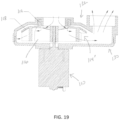
- FIGS. 19-20 another exemplary embodiment of air pump assembly 100 is shown with an impeller 114'.
- the difference between this embodiment and embodiment 1 is that the inner ring of the circular ring cover plate 118 extends a circle of baffle 119 along the circumferential direction, and the baffle 119 extends in the direction away from the motor 110 along the axial direction of the blade 116 of impeller 114'. In this way, the air-tightness of the air inlet can be further improved.
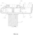
- FIGS. 21-22 another exemplary embodiment of air pump assembly 100 is shown with an impeller 114".
- the difference between this embodiment and the embodiment 2 is that the side of the baffle 119 away from the blade 116 in the axial direction is provided with leak-proof attachment blades 121, and the leak-proof attachment blades 121 are arranged with interval along the circumferential direction of the baffle 118.
Landscapes
- Engineering & Computer Science (AREA)
- Mechanical Engineering (AREA)
- General Engineering & Computer Science (AREA)
- Physics & Mathematics (AREA)
- Fluid Mechanics (AREA)
- Structures Of Non-Positive Displacement Pumps (AREA)
- Compressors, Vaccum Pumps And Other Relevant Systems (AREA)
Claims (15)
- Luftpumpenanordnung (100) für ein aufblasbares Produkt (10) mit einem Innenraum (12), die Folgendes umfasst:ein Gehäuse (120) mit einem Lüftungsloch (200) in Fluidverbindung mit dem Innenraum (12) des aufblasbaren Produkts (10);eine mit dem Gehäuse gekoppelte Abdeckung (240), wobei die Abdeckung (240) mehrere Lüftungsöffnungen (244) aufweist; undeine von dem Gehäuse (120) getragene drehbare Anordnung (104), wobei die drehbare Anordnung (104) Folgendes umfasst:ein Pumpengehäuse (112) mit einem ersten Luftauslass (136) und einem zweiten Luftauslass (138);ein in dem Pumpengehäuse positioniertes Flügelrad (114); undeinen Motor (110), der mit dem Flügelrad operativ gekoppelt ist, um das Flügelrad in Drehung zu versetzen; undeine Drehscheibe (160), die zwischen dem Pumpengehäuse (112) und dem Lüftungsloch (200) des Gehäuses (120) positioniert ist;wobei die drehbare Anordnung (104) in eine erste Position, in der Luft vom ersten Luftauslass (136) des Pumpengehäuses (112) zum zweiten Luftauslass (138) des Pumpengehäuses (112) und anschließend durch die Drehscheibe (16) und das Lüftungsloch (200) im Gehäuse (120) in den Innenraum (12) des aufblasbaren Produkts (10) strömt, und in eine zweite Position drehbar ist, in der Luft vom Innenraum (12) des aufblasbaren Produkts (10) durch das Lüftungsloch (200) im Gehäuse (120) in den ersten Luftauslass (136) des Pumpengehäuses (120) zum zweiten Luftauslass (138) des Pumpengehäuses (120) strömt.
- Luftpumpenanordnung (100) nach Anspruch 1, wobei der Motor (110) eine Orientierung relativ zum ersten Luftauslass (136) des Pumpengehäuses (112) und zum zweiten Luftauslass (138) des Pumpengehäuses (112) beibehält, wenn sich die drehbare Anordnung (104) sowohl in der ersten Position als auch in der zweiten Position befindet.
- Luftpumpenanordnung (100) nach einem der Ansprüche 1 und 2, wobei die drehbare Anordnung (104) ferner ein Drehhandrad (106) umfasst, das sich durch eine Öffnung in der Abdeckung (240) erstreckt.
- Luftpumpenanordnung (100) nach Anspruch 3, wobei der Motor (110) zwischen dem Drehhandrad (106) und dem Pumpengehäuse (112) eingeschlossen ist.
- Luftpumpenanordnung (100) nach Anspruch 4, wobei das Drehhandrad (106) eine Orientierung relativ zum ersten Luftauslass (136) des Pumpengehäuses (112) und zum zweiten Luftauslass (138) des Pumpengehäuses (112) beibehält, wenn sich die drehbare Anordnung (104) sowohl in der ersten Position als auch in der zweiten Position befindet.
- Luftpumpenanordnung (100) nach einem der Ansprüche 1-5, wobei die Drehscheibe (160) vertikal tiefer als das Flügelrad (114) positioniert ist.
- Luftpumpenanordnung (100) nach Anspruch 6, wobei die Drehscheibe (160) einen ersten Luftauslass (162) und einen zweiten Luftauslass (164) aufweist, wobei der erste Luftauslass (162) der Drehscheibe (160) Luft zum ersten Luftauslass (136) des Pumpengehäuses (112) leitet, wenn sich die drehbare Anordnung (104) in der ersten Position befindet, und der erste Luftauslass (162) der Drehscheibe (160) Luft vom ersten Luftauslass (136) des Pumpengehäuses (112) aufnimmt, wenn sich die drehbare Anordnung (104) in der zweiten Position befindet.
- Luftpumpenanordnung (100) nach Anspruch 7, wobei das Drehhandrad (106) eine Orientierung relativ zur Drehscheibe (160) beibehält, wenn sich die drehbare Anordnung (104) sowohl in der ersten als auch in der zweiten Position befindet.
- Luftpumpenanordnung (100) nach Anspruch 7 oder 8, wobei ein Dichtungsring (270) zwischen der Drehscheibe (160) und dem Gehäuse (120) und um das Lüftungsloch (200) im Gehäuse (120) herum angeordnet ist.
- Luftpumpenanordnung (100) nach einem der Ansprüche 6-9, wobei eine Druckplatte (282) die Drehscheibe (160) mit dem Gehäuse (120) koppelt.
- Luftpumpenanordnung (100) nach einem der Ansprüche 1-10, wobei das Flügelrad (114) eine kreisförmige Ringabdeckplatte (118) mit einer mittigen Öffnung und mindestens einen mit der kreisförmigen Ringabdeckplatte (118) verbundenen Flügel (116) umfasst.
- Luftpumpenanordnung (100) nach Anspruch 11, wobei das Flügelrad (114) ferner eine Ablenkplatte (119) umfasst, die sich von der kreisförmigen Ringabdeckplatte (118) in einer ersten Richtung erstreckt, wobei sich der mindestens eine Flügel (116) von der kreisförmigen Ringabdeckplatte (118) in einer zweiten Richtung erstreckt, wobei die zweite Richtung der ersten Richtung entgegengesetzt ist.
- Luftpumpenanordnung (100) nach Anspruch 12, wobei die Ablenkplatte (119) in einer Aussparung im Pumpengehäuse (112) aufgenommen ist.
- Luftpumpenanordnung (100) nach einem der Ansprüche 12 und 13, wobei das Flügelrad (114) ferner mindestens einen sich von der Ablenkplatte (119) erstreckenden Befestigungsflügel (121) umfasst.
- Luftpumpenanordnung (100) nach einem der Ansprüche 1-14, wobei die drehbare Anordnung (104) ferner eine mit dem Motor (110) operativ gekoppelte Leiterplatte (250) und einen mit der Leiterplatte (250) operativ gekoppelten Schalter (230) umfasst, um den Betrieb des Motors (110) zu steuern, wobei die Abdeckung (240) optional eine Steuerplatte (246) umfasst, die mit dem Schalter (230) zusammenwirkt, um den Betrieb des Motors (110) zu steuern.
Applications Claiming Priority (2)
| Application Number | Priority Date | Filing Date | Title |
|---|---|---|---|
| CN202120101406.4U CN215633856U (zh) | 2021-01-14 | 2021-01-14 | 一种充气产品的气泵组件 |
| PCT/IB2022/050303 WO2022153239A2 (en) | 2021-01-14 | 2022-01-14 | Air pump assembly for an inflatable product |
Publications (3)
| Publication Number | Publication Date |
|---|---|
| EP4278095A2 EP4278095A2 (de) | 2023-11-22 |
| EP4278095B1 true EP4278095B1 (de) | 2025-01-29 |
| EP4278095C0 EP4278095C0 (de) | 2025-01-29 |
Family
ID=79831068
Family Applications (1)
| Application Number | Title | Priority Date | Filing Date |
|---|---|---|---|
| EP22700434.8A Active EP4278095B1 (de) | 2021-01-14 | 2022-01-14 | Luftpumpenanordnung für ein aufblasbares produkt |
Country Status (4)
| Country | Link |
|---|---|
| US (1) | US11920610B2 (de) |
| EP (1) | EP4278095B1 (de) |
| CN (1) | CN215633856U (de) |
| WO (1) | WO2022153239A2 (de) |
Families Citing this family (9)
| Publication number | Priority date | Publication date | Assignee | Title |
|---|---|---|---|---|
| CN218062804U (zh) * | 2022-06-20 | 2022-12-16 | 明达实业(厦门)有限公司 | 一种气泵的进气结构和气泵 |
| CN218894779U (zh) * | 2022-11-10 | 2023-04-21 | 明达实业(厦门)有限公司 | 一种泵浦电子切换结构 |
| CN218894780U (zh) * | 2022-11-10 | 2023-04-21 | 明达实业(厦门)有限公司 | 一种泵浦电子调节结构 |
| CN218894775U (zh) * | 2022-11-10 | 2023-04-21 | 明达实业(厦门)有限公司 | 一种泵浦结构 |
| CN221322657U (zh) * | 2023-12-09 | 2024-07-12 | 东莞市红宇塑胶有限公司 | 两用充气泵 |
| CN118601410A (zh) * | 2024-06-11 | 2024-09-06 | 绍兴神洲旅游用品有限公司 | 一种气承与气肋组合帐篷 |
| USD1086215S1 (en) * | 2024-11-19 | 2025-07-29 | Jiangsu Guorun Electric Co., Ltd. | Air pump |
| USD1094466S1 (en) * | 2024-11-19 | 2025-09-23 | Jiangsu Guorun Electric Co., Ltd. | Air pump |
| USD1086216S1 (en) * | 2024-11-19 | 2025-07-29 | Jiangsu Guorun Electric Co., Ltd. | Air pump |
Citations (4)
| Publication number | Priority date | Publication date | Assignee | Title |
|---|---|---|---|---|
| US20100247355A1 (en) * | 2009-03-24 | 2010-09-30 | Foshan Shunde Xinshengyuan Electrical Appliances Co., Ltd. | Built-in electric air pump for inflatable product |
| CN205779787U (zh) * | 2015-11-12 | 2016-12-07 | 明达实业(厦门)有限公司 | 充气产品的自动补气泵 |
| US20170254337A1 (en) * | 2016-03-02 | 2017-09-07 | Sun Pleasure Company Limited | Built-In Air Pump |
| US20170280884A1 (en) * | 2016-04-05 | 2017-10-05 | Bestway Inflatables & Material Corp. | Electric air pump |
Family Cites Families (9)
| Publication number | Priority date | Publication date | Assignee | Title |
|---|---|---|---|---|
| DE20211675U1 (de) * | 2002-07-29 | 2002-09-19 | Yen, Stanley, Taipeh/T'ai-pei | Luftpumpe |
| US6955529B2 (en) | 2003-12-11 | 2005-10-18 | Ho Lee Co., Ltd. | Bidirectional air pump assembly for inflatable objects |
| CN2773356Y (zh) * | 2005-03-02 | 2006-04-19 | 巫新财 | 可调整输气口的输气装置 |
| CN2782996Y (zh) * | 2005-03-11 | 2006-05-24 | 谢森源 | 可调式进出气气泵 |
| CN201391430Y (zh) * | 2009-03-26 | 2010-01-27 | 东莞虎邦五金塑胶制品有限公司 | 充气床垫用手动旋转切换式气泵 |
| US20120107157A1 (en) * | 2010-10-28 | 2012-05-03 | Dongguan Tiger Point, Metal & Plastic Products Co., Ltd. | Air pump having an impeller with double-sided blades |
| CN208294737U (zh) * | 2018-03-02 | 2018-12-28 | 上海荣威塑胶工业有限公司 | 气泵系统 |
| CN212155088U8 (zh) | 2019-06-21 | 2021-03-05 | 上海荣威塑胶工业有限公司 | 充气产品 |
| CN210423098U (zh) * | 2019-07-05 | 2020-04-28 | 明达实业(厦门)有限公司 | 一种气泵和充气系统 |
-
2021
- 2021-01-14 CN CN202120101406.4U patent/CN215633856U/zh active Active
-
2022
- 2022-01-14 EP EP22700434.8A patent/EP4278095B1/de active Active
- 2022-01-14 US US18/027,150 patent/US11920610B2/en active Active
- 2022-01-14 WO PCT/IB2022/050303 patent/WO2022153239A2/en not_active Ceased
Patent Citations (5)
| Publication number | Priority date | Publication date | Assignee | Title |
|---|---|---|---|---|
| US20100247355A1 (en) * | 2009-03-24 | 2010-09-30 | Foshan Shunde Xinshengyuan Electrical Appliances Co., Ltd. | Built-in electric air pump for inflatable product |
| CN205779787U (zh) * | 2015-11-12 | 2016-12-07 | 明达实业(厦门)有限公司 | 充气产品的自动补气泵 |
| US20170254337A1 (en) * | 2016-03-02 | 2017-09-07 | Sun Pleasure Company Limited | Built-In Air Pump |
| US10273966B2 (en) * | 2016-03-02 | 2019-04-30 | Sun Pleasure Company Limited | Built-in air pump |
| US20170280884A1 (en) * | 2016-04-05 | 2017-10-05 | Bestway Inflatables & Material Corp. | Electric air pump |
Also Published As
| Publication number | Publication date |
|---|---|
| CN215633856U (zh) | 2022-01-25 |
| US11920610B2 (en) | 2024-03-05 |
| US20230258199A1 (en) | 2023-08-17 |
| WO2022153239A2 (en) | 2022-07-21 |
| EP4278095A2 (de) | 2023-11-22 |
| EP4278095C0 (de) | 2025-01-29 |
| WO2022153239A3 (en) | 2022-09-09 |
Similar Documents
| Publication | Publication Date | Title |
|---|---|---|
| EP4278095B1 (de) | Luftpumpenanordnung für ein aufblasbares produkt | |
| CN212155088U (zh) | 充气产品 | |
| CN112502498B (zh) | 按摩水池及其气路单元、气路系统和池体 | |
| EP3059451A1 (de) | Eingebaute elektrische aufblaspumpe | |
| EP4083437B1 (de) | Intelligente, eingebaute luftpumpe | |
| JP7554811B2 (ja) | 膨張可能物体を膨張及び収縮するための多様化され取外し可能なポンプシステム及び方法 | |
| EP3754188A1 (de) | Aufblasbares produkt mit elektrischer pumpe und handpumpe | |
| CN210397186U (zh) | 一种电动气泵 | |
| CN108317097A (zh) | 充气泵 | |
| US20120128515A1 (en) | Inflatable and Deflatable Air Pump | |
| CN206129583U (zh) | 一种多气室充放气单独控制装置 | |
| WO2008037136A1 (fr) | Dispositif de gonflage à l'air et de libération d'air | |
| WO2023119254A1 (en) | An air leak proof regulating structure of a mechanical pump | |
| CN212454905U (zh) | 电动气泵的换气结构 | |
| CN201176943Y (zh) | 内置式充气、放气泵 | |
| CN219865373U (zh) | 一种充气气泵与充气帐篷 | |
| CN211300811U (zh) | 一种防褥疮充气床垫控制器 | |
| CN221568925U (zh) | 一种快速充放气泵 | |
| CN210799434U (zh) | 充气产品的电动气泵 | |
| CN219570293U (zh) | 内置气泵 | |
| CN215407680U (zh) | 一种按摩水池及其气路单元、气路系统和池体 | |
| CN213478616U (zh) | 一种集成电磁阀的气泵 | |
| CN224032748U (zh) | 双风道气泵 | |
| CN223282251U (zh) | 一种小型充气泵 | |
| CN210397055U (zh) | 气泵 |
Legal Events
| Date | Code | Title | Description |
|---|---|---|---|
| STAA | Information on the status of an ep patent application or granted ep patent |
Free format text: STATUS: UNKNOWN |
|
| STAA | Information on the status of an ep patent application or granted ep patent |
Free format text: STATUS: THE INTERNATIONAL PUBLICATION HAS BEEN MADE |
|
| PUAI | Public reference made under article 153(3) epc to a published international application that has entered the european phase |
Free format text: ORIGINAL CODE: 0009012 |
|
| STAA | Information on the status of an ep patent application or granted ep patent |
Free format text: STATUS: REQUEST FOR EXAMINATION WAS MADE |
|
| 17P | Request for examination filed |
Effective date: 20230707 |
|
| AK | Designated contracting states |
Kind code of ref document: A2 Designated state(s): AL AT BE BG CH CY CZ DE DK EE ES FI FR GB GR HR HU IE IS IT LI LT LU LV MC MK MT NL NO PL PT RO RS SE SI SK SM TR |
|
| DAV | Request for validation of the european patent (deleted) | ||
| DAX | Request for extension of the european patent (deleted) | ||
| GRAP | Despatch of communication of intention to grant a patent |
Free format text: ORIGINAL CODE: EPIDOSNIGR1 |
|
| STAA | Information on the status of an ep patent application or granted ep patent |
Free format text: STATUS: GRANT OF PATENT IS INTENDED |
|
| INTG | Intention to grant announced |
Effective date: 20240829 |
|
| RAP3 | Party data changed (applicant data changed or rights of an application transferred) |
Owner name: INTEX MARKETING LTD. |
|
| GRAS | Grant fee paid |
Free format text: ORIGINAL CODE: EPIDOSNIGR3 |
|
| GRAA | (expected) grant |
Free format text: ORIGINAL CODE: 0009210 |
|
| STAA | Information on the status of an ep patent application or granted ep patent |
Free format text: STATUS: THE PATENT HAS BEEN GRANTED |
|
| AK | Designated contracting states |
Kind code of ref document: B1 Designated state(s): AL AT BE BG CH CY CZ DE DK EE ES FI FR GB GR HR HU IE IS IT LI LT LU LV MC MK MT NL NO PL PT RO RS SE SI SK SM TR |
|
| REG | Reference to a national code |
Ref country code: GB Ref legal event code: FG4D |
|
| REG | Reference to a national code |
Ref country code: CH Ref legal event code: EP |
|
| REG | Reference to a national code |
Ref country code: DE Ref legal event code: R096 Ref document number: 602022010130 Country of ref document: DE |
|
| REG | Reference to a national code |
Ref country code: IE Ref legal event code: FG4D |
|
| U01 | Request for unitary effect filed |
Effective date: 20250129 |
|
| U07 | Unitary effect registered |
Designated state(s): AT BE BG DE DK EE FI FR IT LT LU LV MT NL PT RO SE SI Effective date: 20250205 |
|
| PG25 | Lapsed in a contracting state [announced via postgrant information from national office to epo] |
Ref country code: RS Free format text: LAPSE BECAUSE OF FAILURE TO SUBMIT A TRANSLATION OF THE DESCRIPTION OR TO PAY THE FEE WITHIN THE PRESCRIBED TIME-LIMIT Effective date: 20250429 |
|
| PG25 | Lapsed in a contracting state [announced via postgrant information from national office to epo] |
Ref country code: PL Free format text: LAPSE BECAUSE OF FAILURE TO SUBMIT A TRANSLATION OF THE DESCRIPTION OR TO PAY THE FEE WITHIN THE PRESCRIBED TIME-LIMIT Effective date: 20250129 |
|
| PG25 | Lapsed in a contracting state [announced via postgrant information from national office to epo] |
Ref country code: ES Free format text: LAPSE BECAUSE OF FAILURE TO SUBMIT A TRANSLATION OF THE DESCRIPTION OR TO PAY THE FEE WITHIN THE PRESCRIBED TIME-LIMIT Effective date: 20250129 |
|
| PG25 | Lapsed in a contracting state [announced via postgrant information from national office to epo] |
Ref country code: IS Free format text: LAPSE BECAUSE OF FAILURE TO SUBMIT A TRANSLATION OF THE DESCRIPTION OR TO PAY THE FEE WITHIN THE PRESCRIBED TIME-LIMIT Effective date: 20250529 Ref country code: NO Free format text: LAPSE BECAUSE OF FAILURE TO SUBMIT A TRANSLATION OF THE DESCRIPTION OR TO PAY THE FEE WITHIN THE PRESCRIBED TIME-LIMIT Effective date: 20250429 |
|
| PG25 | Lapsed in a contracting state [announced via postgrant information from national office to epo] |
Ref country code: HR Free format text: LAPSE BECAUSE OF FAILURE TO SUBMIT A TRANSLATION OF THE DESCRIPTION OR TO PAY THE FEE WITHIN THE PRESCRIBED TIME-LIMIT Effective date: 20250129 |
|
| PG25 | Lapsed in a contracting state [announced via postgrant information from national office to epo] |
Ref country code: GR Free format text: LAPSE BECAUSE OF FAILURE TO SUBMIT A TRANSLATION OF THE DESCRIPTION OR TO PAY THE FEE WITHIN THE PRESCRIBED TIME-LIMIT Effective date: 20250430 |
|
| PG25 | Lapsed in a contracting state [announced via postgrant information from national office to epo] |
Ref country code: SM Free format text: LAPSE BECAUSE OF FAILURE TO SUBMIT A TRANSLATION OF THE DESCRIPTION OR TO PAY THE FEE WITHIN THE PRESCRIBED TIME-LIMIT Effective date: 20250129 |
|
| PG25 | Lapsed in a contracting state [announced via postgrant information from national office to epo] |
Ref country code: CZ Free format text: LAPSE BECAUSE OF FAILURE TO SUBMIT A TRANSLATION OF THE DESCRIPTION OR TO PAY THE FEE WITHIN THE PRESCRIBED TIME-LIMIT Effective date: 20250129 |
|
| PG25 | Lapsed in a contracting state [announced via postgrant information from national office to epo] |
Ref country code: SK Free format text: LAPSE BECAUSE OF FAILURE TO SUBMIT A TRANSLATION OF THE DESCRIPTION OR TO PAY THE FEE WITHIN THE PRESCRIBED TIME-LIMIT Effective date: 20250129 |
|
| PLBE | No opposition filed within time limit |
Free format text: ORIGINAL CODE: 0009261 |
|
| STAA | Information on the status of an ep patent application or granted ep patent |
Free format text: STATUS: NO OPPOSITION FILED WITHIN TIME LIMIT |
|
| 26N | No opposition filed |
Effective date: 20251030 |
|
| U20 | Renewal fee for the european patent with unitary effect paid |
Year of fee payment: 5 Effective date: 20251205 |