EP4276380A2 - Système de montage pour le montage de modules photovoltaïques sur des toits - Google Patents
Système de montage pour le montage de modules photovoltaïques sur des toits Download PDFInfo
- Publication number
- EP4276380A2 EP4276380A2 EP23172462.6A EP23172462A EP4276380A2 EP 4276380 A2 EP4276380 A2 EP 4276380A2 EP 23172462 A EP23172462 A EP 23172462A EP 4276380 A2 EP4276380 A2 EP 4276380A2
- Authority
- EP
- European Patent Office
- Prior art keywords
- floor
- module
- photovoltaic modules
- floor rails
- rails
- Prior art date
- Legal status (The legal status is an assumption and is not a legal conclusion. Google has not performed a legal analysis and makes no representation as to the accuracy of the status listed.)
- Pending
Links
- 239000004575 stone Substances 0.000 description 10
- 230000009183 running Effects 0.000 description 8
- 210000002105 tongue Anatomy 0.000 description 7
- 230000001681 protective effect Effects 0.000 description 4
- XAGFODPZIPBFFR-UHFFFAOYSA-N aluminium Chemical compound [Al] XAGFODPZIPBFFR-UHFFFAOYSA-N 0.000 description 3
- 229910052782 aluminium Inorganic materials 0.000 description 3
- 230000008901 benefit Effects 0.000 description 3
- 230000008092 positive effect Effects 0.000 description 3
- 101100498160 Mus musculus Dach1 gene Proteins 0.000 description 2
- 230000006378 damage Effects 0.000 description 2
- 230000000694 effects Effects 0.000 description 2
- 239000000835 fiber Substances 0.000 description 2
- 238000009434 installation Methods 0.000 description 2
- 239000000463 material Substances 0.000 description 2
- 239000011159 matrix material Substances 0.000 description 2
- 229910000831 Steel Inorganic materials 0.000 description 1
- 230000001154 acute effect Effects 0.000 description 1
- 239000004411 aluminium Substances 0.000 description 1
- 230000008859 change Effects 0.000 description 1
- 238000013461 design Methods 0.000 description 1
- 238000006073 displacement reaction Methods 0.000 description 1
- 238000009826 distribution Methods 0.000 description 1
- 230000009975 flexible effect Effects 0.000 description 1
- 230000001976 improved effect Effects 0.000 description 1
- 238000003780 insertion Methods 0.000 description 1
- 230000037431 insertion Effects 0.000 description 1
- 230000007246 mechanism Effects 0.000 description 1
- 239000004033 plastic Substances 0.000 description 1
- 229920003023 plastic Polymers 0.000 description 1
- 239000010959 steel Substances 0.000 description 1
- 230000008093 supporting effect Effects 0.000 description 1
Images


Classifications
-
- H—ELECTRICITY
- H02—GENERATION; CONVERSION OR DISTRIBUTION OF ELECTRIC POWER
- H02S—GENERATION OF ELECTRIC POWER BY CONVERSION OF INFRARED RADIATION, VISIBLE LIGHT OR ULTRAVIOLET LIGHT, e.g. USING PHOTOVOLTAIC [PV] MODULES
- H02S20/00—Supporting structures for PV modules
- H02S20/20—Supporting structures directly fixed to an immovable object
- H02S20/22—Supporting structures directly fixed to an immovable object specially adapted for buildings
- H02S20/23—Supporting structures directly fixed to an immovable object specially adapted for buildings specially adapted for roof structures
- H02S20/24—Supporting structures directly fixed to an immovable object specially adapted for buildings specially adapted for roof structures specially adapted for flat roofs
-
- F—MECHANICAL ENGINEERING; LIGHTING; HEATING; WEAPONS; BLASTING
- F24—HEATING; RANGES; VENTILATING
- F24S—SOLAR HEAT COLLECTORS; SOLAR HEAT SYSTEMS
- F24S25/00—Arrangement of stationary mountings or supports for solar heat collector modules
- F24S25/10—Arrangement of stationary mountings or supports for solar heat collector modules extending in directions away from a supporting surface
- F24S25/16—Arrangement of interconnected standing structures; Standing structures having separate supporting portions for adjacent modules
-
- F—MECHANICAL ENGINEERING; LIGHTING; HEATING; WEAPONS; BLASTING
- F24—HEATING; RANGES; VENTILATING
- F24S—SOLAR HEAT COLLECTORS; SOLAR HEAT SYSTEMS
- F24S25/00—Arrangement of stationary mountings or supports for solar heat collector modules
- F24S25/30—Arrangement of stationary mountings or supports for solar heat collector modules using elongate rigid mounting elements extending substantially along the supporting surface, e.g. for covering buildings with solar heat collectors
- F24S25/33—Arrangement of stationary mountings or supports for solar heat collector modules using elongate rigid mounting elements extending substantially along the supporting surface, e.g. for covering buildings with solar heat collectors forming substantially planar assemblies, e.g. of coplanar or stacked profiles
- F24S25/37—Arrangement of stationary mountings or supports for solar heat collector modules using elongate rigid mounting elements extending substantially along the supporting surface, e.g. for covering buildings with solar heat collectors forming substantially planar assemblies, e.g. of coplanar or stacked profiles forming coplanar grids comprising longitudinal and transversal profiles
-
- F—MECHANICAL ENGINEERING; LIGHTING; HEATING; WEAPONS; BLASTING
- F24—HEATING; RANGES; VENTILATING
- F24S—SOLAR HEAT COLLECTORS; SOLAR HEAT SYSTEMS
- F24S25/00—Arrangement of stationary mountings or supports for solar heat collector modules
- F24S25/60—Fixation means, e.g. fasteners, specially adapted for supporting solar heat collector modules
- F24S25/61—Fixation means, e.g. fasteners, specially adapted for supporting solar heat collector modules for fixing to the ground or to building structures
- F24S25/617—Elements driven into the ground, e.g. anchor-piles; Foundations for supporting elements; Connectors for connecting supporting structures to the ground or to flat horizontal surfaces
-
- F—MECHANICAL ENGINEERING; LIGHTING; HEATING; WEAPONS; BLASTING
- F24—HEATING; RANGES; VENTILATING
- F24S—SOLAR HEAT COLLECTORS; SOLAR HEAT SYSTEMS
- F24S25/00—Arrangement of stationary mountings or supports for solar heat collector modules
- F24S25/60—Fixation means, e.g. fasteners, specially adapted for supporting solar heat collector modules
- F24S25/65—Fixation means, e.g. fasteners, specially adapted for supporting solar heat collector modules for coupling adjacent supporting elements, e.g. for connecting profiles together
-
- F—MECHANICAL ENGINEERING; LIGHTING; HEATING; WEAPONS; BLASTING
- F24—HEATING; RANGES; VENTILATING
- F24S—SOLAR HEAT COLLECTORS; SOLAR HEAT SYSTEMS
- F24S25/00—Arrangement of stationary mountings or supports for solar heat collector modules
- F24S2025/01—Special support components; Methods of use
- F24S2025/014—Methods for installing support elements
-
- F—MECHANICAL ENGINEERING; LIGHTING; HEATING; WEAPONS; BLASTING
- F24—HEATING; RANGES; VENTILATING
- F24S—SOLAR HEAT COLLECTORS; SOLAR HEAT SYSTEMS
- F24S25/00—Arrangement of stationary mountings or supports for solar heat collector modules
- F24S2025/01—Special support components; Methods of use
- F24S2025/02—Ballasting means
-
- F—MECHANICAL ENGINEERING; LIGHTING; HEATING; WEAPONS; BLASTING
- F24—HEATING; RANGES; VENTILATING
- F24S—SOLAR HEAT COLLECTORS; SOLAR HEAT SYSTEMS
- F24S25/00—Arrangement of stationary mountings or supports for solar heat collector modules
- F24S25/60—Fixation means, e.g. fasteners, specially adapted for supporting solar heat collector modules
- F24S2025/6003—Fixation means, e.g. fasteners, specially adapted for supporting solar heat collector modules by clamping
-
- F—MECHANICAL ENGINEERING; LIGHTING; HEATING; WEAPONS; BLASTING
- F24—HEATING; RANGES; VENTILATING
- F24S—SOLAR HEAT COLLECTORS; SOLAR HEAT SYSTEMS
- F24S25/00—Arrangement of stationary mountings or supports for solar heat collector modules
- F24S25/60—Fixation means, e.g. fasteners, specially adapted for supporting solar heat collector modules
- F24S2025/6005—Fixation means, e.g. fasteners, specially adapted for supporting solar heat collector modules by screwed connection
-
- F—MECHANICAL ENGINEERING; LIGHTING; HEATING; WEAPONS; BLASTING
- F24—HEATING; RANGES; VENTILATING
- F24S—SOLAR HEAT COLLECTORS; SOLAR HEAT SYSTEMS
- F24S25/00—Arrangement of stationary mountings or supports for solar heat collector modules
- F24S25/60—Fixation means, e.g. fasteners, specially adapted for supporting solar heat collector modules
- F24S2025/6007—Fixation means, e.g. fasteners, specially adapted for supporting solar heat collector modules by using form-fitting connection means, e.g. tongue and groove
-
- F—MECHANICAL ENGINEERING; LIGHTING; HEATING; WEAPONS; BLASTING
- F24—HEATING; RANGES; VENTILATING
- F24S—SOLAR HEAT COLLECTORS; SOLAR HEAT SYSTEMS
- F24S25/00—Arrangement of stationary mountings or supports for solar heat collector modules
- F24S25/60—Fixation means, e.g. fasteners, specially adapted for supporting solar heat collector modules
- F24S2025/6008—Fixation means, e.g. fasteners, specially adapted for supporting solar heat collector modules by using toothed elements
Definitions
- the present invention relates to a device according to the preamble of claims 1 to 7, that is to say a mounting system for mounting photovoltaic modules on roofs, in particular on flat roofs.
- photovoltaic modules convert the sun's light directly into electrical energy. They are generally rectangular-shaped panels often mounted on the roofs of buildings.
- cross struts can also be provided.
- cable ducts can also be provided.
- ballast stones can also be provided.
- support elements of different heights are preferably used, so that the photovoltaic modules attached to them can be tilted relative to the horizontal as desired and thus better aligned with the sun.
- flat roofs are understood to mean roofs that have no or only a very small roof inclination, for example a roof inclination of up to 10°.
- a key aspect of a mounting system for photovoltaic systems is how the individual mounting system components and the photovoltaic modules to be attached to them are to be connected to one another. For understandable reasons, the elements to be connected to one another must be in their intended relative position as simply, quickly and safely as possible be connectable. It would also be desirable if the assembly system could be individually adapted to the prevailing conditions with little effort.
- the present invention is therefore based on the object of developing the mounting system according to the preamble of claims 1 to 7 in such a way that the mounting system components to be connected to one another and the photovoltaic modules to be attached to them can be connected to one another quickly and safely in their intended relative position, and at the same time with little Individual adjustments to the prevailing conditions are possible.
- the mounting system described in more detail below is a mounting system for mounting photovoltaic modules on flat roofs.
- flat roofs are understood to mean roofs that have no or only a very small roof inclination, for example a roof inclination of up to 10°. If appropriately adapted to the given conditions, the mounting system can even be used on even more steeply sloping roofs.
- cable ducts, fiber trays and/or other photovoltaic system components can also be provided.
- the photovoltaic modules 1 are rectangular plates with a frame 11, for example made of aluminum, surrounding them on the side.
- the photovoltaic modules 1 are in the example under consideration, arranged in a matrix comprising 3 rows R1, R2, R3 and 3 columns S1, S2, S1, whereby the number of rows and the number of columns can be of any size independently of one another.
- a matrix consisting of several rows and/or several columns is referred to below as a photovoltaic module field.
- the photovoltaic modules 1 are preferably not arranged parallel to the roof surface, but are inclined relative to the roof surface for better alignment with the sun.
- the inclination depends, among other things, on the conditions prevailing at the installation site.
- the photovoltaic modules are inclined so that their light-sensitive surface faces the sun, which is in the south, i.e. so that the edges of the photovoltaic modules facing the south are lower than the edges facing the north.
- the photovoltaic modules 1 of the photovoltaic module series R2 are aligned with the sun standing in the east E, and the photovoltaic modules 1 of the photovoltaic module series R1 and R3 are aligned with the sun standing in the west W.
- the photovoltaic system considered here is an aerodynamic system. This means that it is simply placed on the roof and held in its intended position by its own weight or additional ballast and secured against lifting off.
- the system components In the case of larger roof inclinations, provision can be made for the system components to lie on the roof, i.e. the support plates 2 in the example under consideration, to be partially attached to the roof. This means that a few selected, but not all, support plates 2 can be attached to the roof by screws or in some other way if necessary.
- the photovoltaic modules 1 are arranged on the mounting system in such a way that the long sides of the (rectangular) photovoltaic modules 1 run perpendicular to the floor rails 3, and that the module supports 4, 5, which act as photovoltaic module supports and serve to attach the photovoltaic modules 1 to the mounting system, are arranged along the long sides of the photovoltaic modules 1, i.e. connect the long sides of the photovoltaic modules, more precisely the frames 11 thereof, to the mounting system.
- the module supports 4, 5 are mounted on the floor rails 3, and any number of floor rails 3 spaced as far apart as desired can be provided without accepting disadvantages, by appropriately determining the number and distances of the floor rails 3, one can be optimally adapted to the given conditions Adapted fastening of the photovoltaic modules takes place. In particular, it is also possible to vary the distances between adjacent floor rails 3. At the in the Figures 1 and 2 In the photovoltaic system shown, the distances between adjacent floor rails 3 and thus also the distances between adjacent module supports 4, 5 are smaller in the left half than in the right half of the photovoltaic module field. This has the positive effect that the left area can be exposed to higher mechanical loads, for example higher wind loads or higher snow loads.
- the floor rails 3 no longer rest directly on the roof or a protective mat provided in between, but on the support plates 2 already mentioned.
- these support plates are made of plastic, but in principle they could also be made of any other material.
- they are placed directly on the roof, in particular without a protective mat in between.
- the support plate sections that come into contact with the roof are designed in such a way that they do not have any sharp edges or corners could damage the roof skin and that the desired friction occurs between the roof and the support plate.
- This friction is adjusted so that, on the one hand, the support plates 2 remain immovable on the roof even in unfavorable wind and weather, even without being attached to the roof, and on the other hand, damage to the roof skin due to excessive adhesion of the support plates on the roof is prevented.
- the friction is adjusted by appropriately selecting the size of the contact surface and its surface quality.
- a protective mat (not shown in the figures) can be provided between the support plate 2 and the roof.
- the use of the support plates 2 offers the advantage that the size of the area over which the mounting system comes into contact with the roof can be selected independently of the structure and geometry of the other mounting system components.
- the support plates 2 have a substantially square support surface, the width of which is greater than the width of the bottom rails 3.
- the use of the support plates 2 also offers the advantage that one has more freedom when determining the geometry of the floor rails 3 supported by them.
- the width of the floor rails 3 and the design of the underside of the same are subject to fewer restrictions than before.
- the base rails 3 are placed on the support plates 2. This is for example in Figure 40 clearly visible.
- the bottom rail 3 is placed on by moving the bottom rail 3 from top to bottom.
- the bottom rail 3 comes to rest between two parallel, opposite vertical surfaces 21, 22.
- locking lugs 211 which, when the support plate 2 and base rail 3 are assembled as intended, engage in assigned locking openings 304 in the base rail 3 and thus connect the support plate 2 and the base rail 3 with one another.
- the distance between the vertical surfaces 21, 22 corresponds to the width of the floor rail 3 and the vertical surfaces 21, 22 are elastically movable and/or deformable.
- the vertical surfaces 21, 22 therefore rest laterally on the base rail 3 in the locked state and prevent the base rail 3 from moving in this direction.
- the extent of the latching opening 304 in the longitudinal direction of the floor rail 3 is greater than the extent of the latching lugs 211 in this direction. This makes it possible for the bottom rail 3 to move relative to the support plate 2 in the longitudinal direction of the bottom rail 3. This has the positive effect that changes in the length of the floor rail 3 caused by temperature fluctuations are possible without moving the support plate 2 on the roof.
- the support plate 2 can have two further, parallel, opposite second vertical surfaces 23, 24 between the vertical surfaces 21, 22, which, however, are rotated horizontally (around a vertical axis) by 90 ° to the vertical surfaces 21, 22.
- a floor rail 3 can also be inserted between the second vertical surfaces 23, 24 and attached to it by a locking connection as described above. More precisely, the floor slide 3 can either come to rest between the vertical surfaces 21, 22 or between the vertical surfaces 23, 34.
- the floor rail 3 in particular Figure 8 can be seen has a substantially C-shaped cross section and is placed with the open side first on the support plate 2. For this reason, and because those vertical surfaces 21 - 24 of the support plate 2 that do not lock with the base rail 3 as described are shaped and dimensioned in such a way that they, or more precisely the support plate sections containing them, are within the legs of the base rail 3 Enclosed area can come to rest, placing the bottom rail 3 over these unused support plate sections is not hindered. Quite the opposite: these support plate sections can even have a function that guides the bottom rail 3 when it is put on.
- the mutual distance between the vertical surfaces 21, 22 differs from the mutual distance between the second vertical surfaces 23, 24.
- the support plate 2 and the base rail 3 only have to be aligned with one another in such a way that the base rail 3, more precisely the base rail section to be placed on the support plate 2, comes to lie between those vertical surfaces whose distance corresponds to the width of the relevant base rail section.
- the floor rails 3 in the example under consideration are composed of several first floor rail elements 31, 32 and second floor rail elements 33, 34 that alternate lengthwise, whereby, as in particular from the Figures 8 to 10 can be seen, the first floor rail elements 31, 32 in the second Floor rail elements 33, 34 are inserted and therefore have a smaller width than that of the second floor rail elements 33, 34. Due to the different distances between the vertical surfaces 21, 22 and the second vertical surfaces 23, 24 and a corresponding adjustment of the same to different widths of the first floor rail elements 31, 32 in the second floor rail elements 33, 34, the support plate 2 can be made from support for First floor rail elements 31, 32 serve as a support for floor rail sections formed by the second floor rail elements 33, 34.
- the support plate 2 and the base rail 3 are also adapted to one another in such a way that the sections of the support plate 2 that protrude furthest upwards are flush with the top of the base rail 3 that is placed on the support plate 2 as intended.
- the support plate 2 can also be used as an additional support for objects to be placed on the floor rail 3.
- objects are, for example, but not exclusively, the ballast stones 7.
- a ballast stone 7 can be placed so that it rests both on the floor rail 3 and on the support plate 2 carrying it.
- the ballast stone rests on support points located far away from the bottom rail 3 and is thus well secured against slipping off the bottom rail .
- cross struts 6 running perpendicular to the floor rails 3, as in the Figure 39 shown on the module supports 5, more precisely on the terminal supports 52 of the same, or as in Figure 40 shown are attached to the floor rails 3, ballast stones 7 can be placed.
- the floor rails 3 are each composed of several floor rail elements arranged one behind the other in a row and connected to one another. These floor rail elements include first floor rail elements 31, 32 and second floor rail elements 33, 34, which alternately follow one another.
- the first floor rail element 31 is in Figure 6 shown, the first floor rail element 32 in Figure 7 , the second floor rail element 33 in Figure 4 , and the second floor rail element 34 in Figure 5 .
- the first floor rail elements 31, 32 essentially only differ in their length.
- the shorter first floor rail element 32 is approximately half as long as the longer first floor rail element 31 and is used in the present case if only a single high module support 5 is to be attached to it, i.e. if the floor rail element in question is the front or rear end of a respective floor rail 3 forms.
- the longer first floor rail element 31 is used in the example under consideration when two high module supports 5 are to be attached to it, i.e. when the floor rail element in question comes to rest between two second floor rail elements 33, 34.
- the shorter second floor rail element 34 is approximately half as long as the longer second floor rail element 33 and is used in the present case if only a single low module support 4 is to be attached to it, i.e. if the floor rail element in question is the front or rear end of a respective floor rail 3 forms.
- the longer second floor rail element 33 is used in the example under consideration when two low module supports 4 are to be attached to it, i.e. when the floor rail element in question comes to rest between two first floor rail elements 31, 32.
- the bottom rail elements 31 - 34 each have a substantially C-shaped cross section, with - based on the intended position of the bottom rail elements on the support plate 2 - two vertical legs 301 lying parallel to one another at a distance and one connecting the upper ends of the same horizontal leg 302, the lower ends 303 of the vertical legs being bent inwards to form an acute angle.
- the floor rail elements are made of steel, but could also be made of another material.
- the floor rail elements 31 - 34 have various recesses and other structures in their horizontal and vertical legs.
- locking openings 304 include, among other things, the locking openings 304 already mentioned above, which are assigned to the locking lugs 211 of the support plates 2.
- These locking openings 304 are provided on both vertical legs 301 of all floor rail elements 31 - 34.
- a plurality of such locking openings 304 are provided on each vertical leg of each floor rail element 31 - 34. More precisely, a row of locking openings 304 is provided which runs in the longitudinal direction of the floor rail elements and extends over the entire length of the floor rail elements.
- the many locking openings 304 make it possible for the position of each support plate 2 to be selected from a variety of possible positions, and/or for the number of support plates 2 used to be set within wide limits, so that it is very flexible The number and positions of the support plates can be adjusted to the given conditions.
- opposite bulges 305 are also provided, in the middle of which there is a hole designed for inserting a rivet.
- the bulges 305 are intended to accommodate the rivet heads lying between the vertical legs 301 so that they do not protrude into the space enclosed by the bottom rail element legs 301, 302. This enables unhindered insertion of the first floor rail elements 31, 32 into the second floor rail elements 33, 34.
- Such telescoping is necessary for the type of connection of adjacent floor rail elements selected in the example under consideration. This will be discussed in more detail later.
- the rivets in question are used to fasten the module supports to be attached to the second floor rail elements 33, 34, more precisely for attaching the high module supports 5. This will also be discussed in more detail later.
- One or more elastically movable tongues 331 are formed on the horizontal legs 302 of the second floor rail elements 33, 34, which were created by a U-shaped incision in the horizontal leg 302.
- the free ends of the tongues 331 are formed by a corresponding deformation as a locking lug 3311, which is designed to snap into one of the assigned locking openings 311-1 - 311-3 in the horizontal leg 302 of a first floor rail element inserted into the second floor rail element 33, 34 .
- This locking mechanism which is used to connect adjacent floor rail elements, will be described in more detail later.
- Locking recesses 332 are also provided in the horizontal legs 302 of the second floor rail elements 33, 34. These locking recesses 332 come when two floor rail elements to be connected to one another are pushed far into one another, i.e. when the locking lug 3311 of the tongue 331 of the second floor rail element 33, 34 falls into one of several assigned locking openings 311-1 - 311-3 of the first floor rail element 31 , 32 is locked to lie over one of several locking recesses 312-1 - 312-3 of the first floor rail element 31, 32.
- the locking recesses that lie one above the other are passed through by a locking extension 521 extending from the high module support 5.
- the nested first and second floor rail elements are additionally secured against mutual displacement.
- first floor rail elements 31, 32 in addition to the locking openings 304 already mentioned above, there are in the vertical legs 301 and the locking openings 311-1 to 311-3, also mentioned above, and locking recesses 312-1 to 312-3 in the horizontal ones Legs 302 further recesses 313-1 - 313-4 and locking openings 314 for fastening the low module supports 4 to the first floor rails 31, 32 are provided. This will be discussed in more detail later.
- markings 315-1 - 315-3 on the horizontal legs 302 of the first floor rail elements 31, 32 which show how far the first floor rail elements 31, 32 and the second floor rail elements 33, 34 are pushed into one another.
- various additional recesses are provided on the floor rail elements 31 - 34. These are used to attach other components of the photovoltaic system, for example to attach cross struts etc. to the floor rail elements 31 - 34. The attachment of such and other system components to the floor rail elements is of secondary interest in the present case and is therefore not explained in more detail here.
- the first floor rail elements 31, 32 and the second floor rail elements 33, 34 are designed for attaching different module supports 4, 5.
- the low module supports 4 are mounted on the first floor rail elements 31, 32, and only on these
- the high module supports 5 are mounted on the second floor rail elements 33, 34, and only on these.
- this could also be exactly the other way around, so that the high module supports 5 are mounted on the first floor rail elements 31, 32, and the low module supports 4 are mounted on the second floor rail elements 33, 34.
- all photovoltaic modules 1 are inclined in exactly the same way, for example aligned with the sun in the south, provision could also be made for low module supports 4 and high module supports 5 to be mounted on a floor rail element.
- the first floor rail elements 31, 32 and the second floor rail elements 33, 34 are designed to be pushed into one another in order to connect them. More precisely, in the example under consideration, it is the case that the second floor rail elements 33, 34 have a slightly larger cross section than the first floor rail elements 31, 32, so that the first floor rail elements 31, 32 as in the Figures 8 to 10 illustrated can be inserted into the second floor rail elements 33, 34. Of course, this can also be exactly the other way around.
- the first floor rail elements 31, 32 and the second floor rail elements 33, 34 are connected to one another when they are pushed far into one another as intended, so that no further relative movements are possible.
- this connection includes a Snap connection, although there is no restriction on this.
- the already mentioned locking lug 3311 is located on an elastically movable section, namely on the tongue 331 of the second floor rail elements 33, 34, which locks into an assigned locking opening 311-1 - 311-3 when the floor rail elements are pushed into one another in the intended relative position .
- the first floor rail elements 31, 32 and the second floor rail elements 33, 34 can be pushed into one another to different extents to adapt to the given conditions. More precisely, there are several different relative positions in which they can be connected to each other.
- the floor rail elements are designed to be connected to one another in one of three predetermined relative positions, with no restriction to the number 3. In each of the predetermined relative positions, the floor rail elements can be connected to one another in exactly the same way.
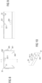
- the Figures 13 to 15 show the state in which the first floor rail elements 31, 32 are pushed as far as possible into the second floor rail elements 33, 34.
- the locking lug 3311 is in the locking opening 311-1. This can be reliably verified from the outside using the three markings 315-1 - to 315-3.
- the second floor rail element 33, 34 ends at the marking 315-1.
- the locking recess 312-1 of the first floor rail element 31, 32 also comes to rest under the locking recess 332 of the second floor rail element 33, 34, so that the floor rail elements are secured by means of the locking extension 521 of the high module support 5 in. which runs through these locking recesses be locked in this position.
- the Figures 19 to 21 show the state in which the first floor rail elements 31, 32 are inserted a minimum distance into the second floor rail elements 33, 34.
- the locking lug 3311 is in the locking opening 311-3, and the second floor rail element 33, 34 ends at the marking 315-3.
- the locking recess 312-3 of the first floor rail element 31, 32 also comes to lie under the locking recess 332 of the second floor rail element 33, 34, so that the floor rail elements are secured by means of of the locking extension 521 of the high module support 5 running through these locking recesses can be locked in this position.
- the Figures 16 to 18 show the state in which the first floor rail elements 31, 32 are inserted into the second floor rail elements 33, 34 to an extent lying between the minimum and the maximum.
- the locking lug 3311 is in the locking opening 311-2, and the second floor rail element 33, 34 ends at the marking 315-2.
- the locking recess 312-2 of the first floor rail element 31, 32 also comes to rest under the locking recess 332 of the second floor rail element 33, 34, so that the floor rail elements are secured by means of the locking extension 521 of the high module support which runs through these locking recesses 5 must be locked in this position.
- the low module supports 4 are mounted on the first floor rail elements 31, 32, and the high module supports 5 are mounted on the second floor rail elements 33, 34.
- module clamps 41 and 51 that can be connected to the photovoltaic modules as well as clamp supports 42 and 52 that are connected to the floor rails and the module clamps and arranged between them and are connected to one another in this way are that the module clamps can be pivoted in relation to the clamp supports and/or the clamp supports can be pivoted in relation to the floor rails.
- the module clamps are designated with the reference number 41 and the clamp supports are designated with the reference number 42, and of the components mentioned of the high module supports 5, the module clamps are designated with the reference number 51 and the clamp supports are designated with the reference number 52 .
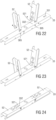
- the assembly of the high module supports 5 on the second floor rail elements 33, 34 is in the Figures 22 to 27 illustrated.
- the terminal carrier 52 is formed by a hat profile, whose - based on its in the Figure 24 shown, completely folded down position - vertical legs have a distance corresponding to the width of the second floor rail element, so that the clamp carrier can be placed on the second floor rail element 33, 34 from above or as in the Figure 24 shown can be folded all the way down. Holes are provided in the vertical legs of the clamp carrier 52 for attaching the clamp carrier to the second floor rail element 33, 34 and for attaching the module clamp 51 to the clamp carrier.
- the clamp carrier 52 is fastened by rivets which pass through the holes provided for this purpose in the clamp carrier 52 and the holes provided in the bulges 305 of the second base rail element 33, 34.
- the inner heads of the rivets come to lie within the bulges 305 and therefore do not form an obstacle that interferes with the telescoping of the bottom rail elements.
- the two opposing rivets, through which each clamp carrier 52 is connected to the second floor rail element 33, 34, form a horizontal pivot axis running perpendicular to the floor rail, about which the clamp carrier 52 can be swiveled up and down.
- the terminal supports 52 are almost vertical, and in the state shown in the Figure 24 In the state shown, they are folded all the way down and rest on the second floor rail element.
- the folded-up position is one of the possible positions of the terminal carrier 52, which it can assume when it is connected to a photovoltaic module 1 as intended.
- the position folded all the way down is the position of the clamp carrier 52, which it preferably assumes during transport when it is pre-assembled on the second floor rail element 33, 34.
- the terminal carrier 52 can also be other than those in the Figure 23 assume the folded-up positions shown, for example, but not exclusively, those in the Figures 15, 18 and 21 positions shown.
- locking extension 521 of the high module support 5 is also clearly visible.
- This locking extension 521 works in the example under consideration from the horizontal leg of the clamp carrier 52 and is arranged and designed so that it is in the folded up position of the clamp carrier 52, for example in the Figure 23 position shown, the locking recess 332 of the second floor rail element 33, 34 and the underlying locking recess 312-1 or 312-2 or 312-3 of the first floor rail element 31, 32 passes through and secures against relative movements of the same.
- the clamp 51 comprises a lower part 511 and an upper part 512, which are connected to one another using a screw 513 or the like and can be moved far towards or away from one another as desired, and between which the photovoltaic module 1 to be clamped, more precisely the frame, is located 11 of the same can be trapped.
- the lower terminal part 511 is connected to the terminal carrier 52 by a screw 514.
- the screw 514 passes through the holes provided in the vertical legs of the clamp carrier 52 as well as assigned holes in the lower part of the clamp 511.
- the screw forms a horizontal axis that runs perpendicular to the base rail, about which the module clamp 51 can be pivoted. The fact that not only the clamp carrier 52, but also the module clamp 51 can be pivoted, makes the mounting system even better adaptable to the given conditions than is already the case.
- the module clamp 51 can also be formed by a pair of module clamps, whereby the several module clamps can be connected either to the same photovoltaic module or to different photovoltaic modules 1.
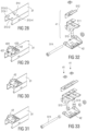
- the assembly of the low module supports 4 on the first floor rail elements 31, 32 is in the Figures 28 to 33 illustrated.
- the clamp carrier 42 is formed by a plate that lies on the first floor rail element 31, 32 and has two side parts that extend vertically upwards and run in the longitudinal direction of the floor rail, in which holes are provided for fastening the module clamp 41 to the clamp carrier 42.
- Four angled legs extend from the plate, which initially extend slightly downwards from the plate and then continue to run parallel to the plate in the longitudinal direction of the floor rail.
- An elastically movable tongue 422 is also formed in the plate by a U-shaped incision, at the free end of which a locking lug 423 is formed.
- the clamp carrier 42 is as shown in FIG Figures 29 and 30 shown placed on the first floor rail element 31, 32 so that its legs 421 pass through the assigned recesses 313-1 - 313-4 of the first floor rail element 31, 32. Then, as in Figure 31 shown, the clamp carrier 42 is pushed as far as it will go in the longitudinal direction of the bottom rail element 31, 32. In the state then reached, the locking lug 423 of the clamp carrier 42 snaps into the assigned locking opening 314 of the first floor rail element 31, 32 and fixes the clamp carrier 42 in this position.
- the Figure 32 shows how the module clamp 41 is attached to the clamp carrier 42.
- the structure of the module clamp 41 corresponds to the structure of the module clamp 51 already described in detail.
- the same reference numbers designate the same or corresponding elements.
- the module clamp is again attached to the clamp carrier with a screw 514.
- the screw 514 passes through the holes provided for this purpose on the clamp carrier 42 as well as associated holes in the lower clamp part 511 and here too forms a horizontal axis running perpendicular to the base rail, about which the module clamp 41 can be pivoted like the module clamp 51. Thanks to the several pairs of holes for the screw 514 in the lower part of the clamp, the clamp 41 can also be fastened to the clamp carrier 42 in different relative positions.
- the module clamp 41 can also be formed by a pair of module clamps, whereby the several module clamps can be connected either to the same photovoltaic module 1 or to different photovoltaic modules.
- the pivotability of the module clamp 41 in relation to the clamp carrier 42 and/or the possibility of being able to attach the module clamp 41 to the clamp carrier 42 in different relative positions enables further adjustments of the mounting system to the given conditions.
- the pivotability of the module clamp 41 also enables faster and easier installation of the photovoltaic modules 1 on the mounting system. This is in the Figures 34 - 36 illustrated. If you swivel the module clamp 41 as shown Figure 34 shown to the rear as far as it will go, then the photovoltaic module 1 can simply be placed vertically on the module clamp so that it, or more precisely its frame 11, comes to rest between the lower part of the clamp and the upper part of the clamp. By subsequently tightening the screw connecting the lower part of the clamp and the upper part of the clamp, the photovoltaic module frame 11 is as shown in FIG Figure 35 shown clamped between the lower part of the terminal and the upper part of the terminal and held there.
Landscapes
- Engineering & Computer Science (AREA)
- Chemical & Material Sciences (AREA)
- Thermal Sciences (AREA)
- General Engineering & Computer Science (AREA)
- Physics & Mathematics (AREA)
- Life Sciences & Earth Sciences (AREA)
- Sustainable Development (AREA)
- Sustainable Energy (AREA)
- Mechanical Engineering (AREA)
- Combustion & Propulsion (AREA)
- Architecture (AREA)
- Civil Engineering (AREA)
- Structural Engineering (AREA)
- Roof Covering Using Slabs Or Stiff Sheets (AREA)
- Photovoltaic Devices (AREA)
Applications Claiming Priority (1)
| Application Number | Priority Date | Filing Date | Title |
|---|---|---|---|
| DE202022102550.9U DE202022102550U1 (de) | 2022-05-10 | 2022-05-10 | Montagesystem zur Montage von Photovoltaikmodulen auf Dächern |
Publications (2)
| Publication Number | Publication Date |
|---|---|
| EP4276380A2 true EP4276380A2 (fr) | 2023-11-15 |
| EP4276380A3 EP4276380A3 (fr) | 2024-02-21 |
Family
ID=83282892
Family Applications (2)
| Application Number | Title | Priority Date | Filing Date |
|---|---|---|---|
| EP23161635.0A Pending EP4276381A3 (fr) | 2022-05-10 | 2023-03-13 | Système de montage pour le montage de modules photovoltaïques sur des toits |
| EP23172462.6A Pending EP4276380A3 (fr) | 2022-05-10 | 2023-05-09 | Système de montage pour le montage de modules photovoltaïques sur des toits |
Family Applications Before (1)
| Application Number | Title | Priority Date | Filing Date |
|---|---|---|---|
| EP23161635.0A Pending EP4276381A3 (fr) | 2022-05-10 | 2023-03-13 | Système de montage pour le montage de modules photovoltaïques sur des toits |
Country Status (2)
| Country | Link |
|---|---|
| EP (2) | EP4276381A3 (fr) |
| DE (1) | DE202022102550U1 (fr) |
Families Citing this family (1)
| Publication number | Priority date | Publication date | Assignee | Title |
|---|---|---|---|---|
| NL2033469B1 (en) | 2022-11-04 | 2024-05-24 | Tinteq Holding B V | Frame part for supporting at least one solar panel with respect to a support surface, frame and solar system and method for mounting solar panels |
Family Cites Families (15)
| Publication number | Priority date | Publication date | Assignee | Title |
|---|---|---|---|---|
| US20100269428A1 (en) * | 2007-05-23 | 2010-10-28 | Robert Stancel | Cost Effective, Elongate Member Mounting System For Photovoltaic Devices |
| DE102009019829A1 (de) * | 2009-05-04 | 2010-11-11 | Gehrlicher Solar Ag | Befestigungsstruktur für ein großflächiges Solarmodul und Solarmodul |
| DE202009007490U1 (de) * | 2009-05-26 | 2009-08-20 | Green Factory Gmbh | Vorrichtung zur Befestigung eines Moduls zur Nutzung von Sonnenenergie |
| US8615939B2 (en) * | 2009-10-15 | 2013-12-31 | Sunlink Corporation | Photovoltaic module mounting system |
| EP2362161B1 (fr) * | 2010-02-22 | 2012-11-07 | B&L | Système de montage de panneaux |
| US20110233157A1 (en) * | 2010-03-22 | 2011-09-29 | JAC-Rack, Inc. | Solar panel mounting system and method |
| ITMI20101484A1 (it) * | 2010-08-04 | 2012-02-05 | Gianazza Angelo S P A | Elemento di connessione per strutture di supporto per pannelli solarie struttura comprendente piu' elementi ed una serie di tubi o barre colleganti piu' elementi |
| DE102011102239A1 (de) * | 2011-05-20 | 2012-11-22 | Robert Bosch Gmbh | Solarmodulanordnung mit Haltenut und zugeordnetem Füllteil |
| US9038329B2 (en) * | 2011-10-11 | 2015-05-26 | Sunlink Corporation | Structure following roof mounted photovoltaic system |
| CN102903772B (zh) * | 2012-09-26 | 2015-09-30 | 友达光电股份有限公司 | 太阳能设备及其组装系统 |
| WO2014123547A1 (fr) * | 2013-02-11 | 2014-08-14 | Port Jonathan | Montage de bride modulaire pour des panneaux solaires |
| CA2830914C (fr) * | 2013-10-11 | 2018-06-26 | Polar Racking Inc. | Support pour panneau solaire |
| CA2935399A1 (fr) * | 2014-01-16 | 2015-07-23 | Jonathan PORT | Appareil et procedes pour la fixation d'attaches de couverture et d'elements structuraux sur des toits |
| CN204349866U (zh) * | 2015-01-29 | 2015-05-20 | 丽瀑能源工程技术(上海)有限公司 | 屋面光伏的铝支架 |
| DE202018103244U1 (de) * | 2018-06-08 | 2018-06-22 | Premium Mounting Technologies GmbH & Co. KG | Montagesystem zur Montage von Photovoltaikmodulen auf Dächern, mit durch Rastverbindungen verbundenen Montagesystem-Komponenten |
-
2022
- 2022-05-10 DE DE202022102550.9U patent/DE202022102550U1/de active Active
-
2023
- 2023-03-13 EP EP23161635.0A patent/EP4276381A3/fr active Pending
- 2023-05-09 EP EP23172462.6A patent/EP4276380A3/fr active Pending
Also Published As
| Publication number | Publication date |
|---|---|
| DE202022102550U1 (de) | 2022-08-29 |
| EP4276381A2 (fr) | 2023-11-15 |
| EP4276380A3 (fr) | 2024-02-21 |
| EP4276381A3 (fr) | 2024-02-21 |
Similar Documents
| Publication | Publication Date | Title |
|---|---|---|
| DE69333452T2 (de) | Befestigungsvorrichtung für gebäudeoberflächen | |
| DE202012004333U1 (de) | Vorrichtung zum Abstützen zumindest eines Solarmoduls | |
| DE202009018534U1 (de) | Montagesystem | |
| EP2843320A1 (fr) | Support de module | |
| EP3803228B1 (fr) | Système de montage pour monter des modules photovoltaïques sur des toits, comprenant des composants de système de montage reliés par des moyens d'assemblage par encliquetage | |
| EP4276380A2 (fr) | Système de montage pour le montage de modules photovoltaïques sur des toits | |
| EP4053469A1 (fr) | Cadre porteur destiné à la fixation inclinée d'un module solaire sur un toit | |
| EP2378563A2 (fr) | Système de montage pour module solaire | |
| DE102012016797B4 (de) | Dachunterbau in Zickzackform | |
| WO2011029824A1 (fr) | Ensemble modulaire composé de modules solaires | |
| DE102022111700A1 (de) | Montagesystem zur Montage von Photovoltaikmodulen auf Dächern | |
| DE202012001526U1 (de) | Montageeinheit für Photovoltaikmodule, insbesondere auf Flachdächern, und Anordnung einer Vielzahl von beiden | |
| DE202018103246U1 (de) | Montagesystem zur Montage von Photovoltaikmodulen auf Dächern, mit Wasserableitungsvorrichtung | |
| DE102013011260A1 (de) | Abstandshalter für Solarmodulträger | |
| DE102018125957B3 (de) | Montageverfahren zur Montage einer Modulbaugruppenkonstruktion und insbesondere zur Montage von Photovoltaikanlagen | |
| EP2270403A1 (fr) | Rail de support | |
| WO2019234188A1 (fr) | Système de montage conçu pour monter des modules photovoltaïques sur des toits, comprenant un dispositif anti-chute | |
| EP3690347A1 (fr) | Installation solaire et dispositif de retenue destiné au montage d'au moins un module solaire sur un support | |
| DE102018001170A1 (de) | Verbindungssystem für sich kreuzende Profile mit einstellbaren Verbindungselementen, Solaranlage, Freiflächenanlage, Dach, Carport mit dem System der Hebeschiebetechnik | |
| DE102010062026A1 (de) | Stützkörper und Stützelement für eine Solarunterkonstruktion sowie Solarunterkonstruktion zur Montage mindestens eines Solarmoduls | |
| DE202016002486U1 (de) | Solarmodulanordnung und Solaranlage | |
| DE102021129381A1 (de) | Montagegestell zum halten mindestens eines photovoltaikmoduls und photovoltaik-anordnung | |
| DE202023002783U1 (de) | Dachhalterung für plattenförmige Module | |
| DE102023105249A1 (de) | Vorrichtung und Verfahren zur Freiland-Aufstellung von Einzelsolarmodulen und Solarmodulen auf einem Untergrund | |
| DE102022113181A1 (de) | Traggestell zu einer schrägen Befestigung eines Solarmoduls auf einem Dach |
Legal Events
| Date | Code | Title | Description |
|---|---|---|---|
| PUAI | Public reference made under article 153(3) epc to a published international application that has entered the european phase |
Free format text: ORIGINAL CODE: 0009012 |
|
| STAA | Information on the status of an ep patent application or granted ep patent |
Free format text: STATUS: THE APPLICATION HAS BEEN PUBLISHED |
|
| AK | Designated contracting states |
Kind code of ref document: A2 Designated state(s): AL AT BE BG CH CY CZ DE DK EE ES FI FR GB GR HR HU IE IS IT LI LT LU LV MC ME MK MT NL NO PL PT RO RS SE SI SK SM TR |
|
| PUAL | Search report despatched |
Free format text: ORIGINAL CODE: 0009013 |
|
| AK | Designated contracting states |
Kind code of ref document: A3 Designated state(s): AL AT BE BG CH CY CZ DE DK EE ES FI FR GB GR HR HU IE IS IT LI LT LU LV MC ME MK MT NL NO PL PT RO RS SE SI SK SM TR |
|
| RIC1 | Information provided on ipc code assigned before grant |
Ipc: F24S 25/00 20180101ALN20240118BHEP Ipc: F24S 25/60 20180101ALN20240118BHEP Ipc: F24S 25/617 20180101ALI20240118BHEP Ipc: F24S 25/37 20180101ALI20240118BHEP Ipc: F24S 25/16 20180101ALI20240118BHEP Ipc: H02S 20/24 20140101ALI20240118BHEP Ipc: F24S 25/65 20180101ALI20240118BHEP Ipc: F24S 25/33 20180101ALI20240118BHEP Ipc: F24S 25/10 20180101AFI20240118BHEP |
|
| STAA | Information on the status of an ep patent application or granted ep patent |
Free format text: STATUS: REQUEST FOR EXAMINATION WAS MADE |